WO2017077808A1 - 車両の制御装置 - Google Patents
車両の制御装置 Download PDFInfo
- Publication number
- WO2017077808A1 WO2017077808A1 PCT/JP2016/079720 JP2016079720W WO2017077808A1 WO 2017077808 A1 WO2017077808 A1 WO 2017077808A1 JP 2016079720 W JP2016079720 W JP 2016079720W WO 2017077808 A1 WO2017077808 A1 WO 2017077808A1
- Authority
- WO
- WIPO (PCT)
- Prior art keywords
- soc
- discharge
- vehicle
- behavior
- battery
- Prior art date
- Legal status (The legal status is an assumption and is not a legal conclusion. Google has not performed a legal analysis and makes no representation as to the accuracy of the status listed.)
- Ceased
Links
Images


Classifications
-
- B—PERFORMING OPERATIONS; TRANSPORTING
- B60—VEHICLES IN GENERAL
- B60L—PROPULSION OF ELECTRICALLY-PROPELLED VEHICLES; SUPPLYING ELECTRIC POWER FOR AUXILIARY EQUIPMENT OF ELECTRICALLY-PROPELLED VEHICLES; ELECTRODYNAMIC BRAKE SYSTEMS FOR VEHICLES IN GENERAL; MAGNETIC SUSPENSION OR LEVITATION FOR VEHICLES; MONITORING OPERATING VARIABLES OF ELECTRICALLY-PROPELLED VEHICLES; ELECTRIC SAFETY DEVICES FOR ELECTRICALLY-PROPELLED VEHICLES
- B60L58/00—Methods or circuit arrangements for monitoring or controlling batteries or fuel cells, specially adapted for electric vehicles
- B60L58/10—Methods or circuit arrangements for monitoring or controlling batteries or fuel cells, specially adapted for electric vehicles for monitoring or controlling batteries
- B60L58/12—Methods or circuit arrangements for monitoring or controlling batteries or fuel cells, specially adapted for electric vehicles for monitoring or controlling batteries responding to state of charge [SoC]
- B60L58/13—Maintaining the SoC within a determined range
-
- B—PERFORMING OPERATIONS; TRANSPORTING
- B60—VEHICLES IN GENERAL
- B60K—ARRANGEMENT OR MOUNTING OF PROPULSION UNITS OR OF TRANSMISSIONS IN VEHICLES; ARRANGEMENT OR MOUNTING OF PLURAL DIVERSE PRIME-MOVERS IN VEHICLES; AUXILIARY DRIVES FOR VEHICLES; INSTRUMENTATION OR DASHBOARDS FOR VEHICLES; ARRANGEMENTS IN CONNECTION WITH COOLING, AIR INTAKE, GAS EXHAUST OR FUEL SUPPLY OF PROPULSION UNITS IN VEHICLES
- B60K35/00—Instruments specially adapted for vehicles; Arrangement of instruments in or on vehicles
- B60K35/20—Output arrangements, i.e. from vehicle to user, associated with vehicle functions or specially adapted therefor
- B60K35/28—Output arrangements, i.e. from vehicle to user, associated with vehicle functions or specially adapted therefor characterised by the type of the output information, e.g. video entertainment or vehicle dynamics information; characterised by the purpose of the output information, e.g. for attracting the attention of the driver
-
- B—PERFORMING OPERATIONS; TRANSPORTING
- B60—VEHICLES IN GENERAL
- B60K—ARRANGEMENT OR MOUNTING OF PROPULSION UNITS OR OF TRANSMISSIONS IN VEHICLES; ARRANGEMENT OR MOUNTING OF PLURAL DIVERSE PRIME-MOVERS IN VEHICLES; AUXILIARY DRIVES FOR VEHICLES; INSTRUMENTATION OR DASHBOARDS FOR VEHICLES; ARRANGEMENTS IN CONNECTION WITH COOLING, AIR INTAKE, GAS EXHAUST OR FUEL SUPPLY OF PROPULSION UNITS IN VEHICLES
- B60K6/00—Arrangement or mounting of plural diverse prime-movers for mutual or common propulsion, e.g. hybrid propulsion systems comprising electric motors and internal combustion engines
- B60K6/20—Arrangement or mounting of plural diverse prime-movers for mutual or common propulsion, e.g. hybrid propulsion systems comprising electric motors and internal combustion engines the prime-movers consisting of electric motors and internal combustion engines, e.g. HEVs
- B60K6/42—Arrangement or mounting of plural diverse prime-movers for mutual or common propulsion, e.g. hybrid propulsion systems comprising electric motors and internal combustion engines the prime-movers consisting of electric motors and internal combustion engines, e.g. HEVs characterised by the architecture of the hybrid electric vehicle
- B60K6/44—Series-parallel type
- B60K6/442—Series-parallel switching type
-
- B—PERFORMING OPERATIONS; TRANSPORTING
- B60—VEHICLES IN GENERAL
- B60K—ARRANGEMENT OR MOUNTING OF PROPULSION UNITS OR OF TRANSMISSIONS IN VEHICLES; ARRANGEMENT OR MOUNTING OF PLURAL DIVERSE PRIME-MOVERS IN VEHICLES; AUXILIARY DRIVES FOR VEHICLES; INSTRUMENTATION OR DASHBOARDS FOR VEHICLES; ARRANGEMENTS IN CONNECTION WITH COOLING, AIR INTAKE, GAS EXHAUST OR FUEL SUPPLY OF PROPULSION UNITS IN VEHICLES
- B60K6/00—Arrangement or mounting of plural diverse prime-movers for mutual or common propulsion, e.g. hybrid propulsion systems comprising electric motors and internal combustion engines
- B60K6/20—Arrangement or mounting of plural diverse prime-movers for mutual or common propulsion, e.g. hybrid propulsion systems comprising electric motors and internal combustion engines the prime-movers consisting of electric motors and internal combustion engines, e.g. HEVs
- B60K6/42—Arrangement or mounting of plural diverse prime-movers for mutual or common propulsion, e.g. hybrid propulsion systems comprising electric motors and internal combustion engines the prime-movers consisting of electric motors and internal combustion engines, e.g. HEVs characterised by the architecture of the hybrid electric vehicle
- B60K6/44—Series-parallel type
- B60K6/445—Differential gearing distribution type
-
- B—PERFORMING OPERATIONS; TRANSPORTING
- B60—VEHICLES IN GENERAL
- B60K—ARRANGEMENT OR MOUNTING OF PROPULSION UNITS OR OF TRANSMISSIONS IN VEHICLES; ARRANGEMENT OR MOUNTING OF PLURAL DIVERSE PRIME-MOVERS IN VEHICLES; AUXILIARY DRIVES FOR VEHICLES; INSTRUMENTATION OR DASHBOARDS FOR VEHICLES; ARRANGEMENTS IN CONNECTION WITH COOLING, AIR INTAKE, GAS EXHAUST OR FUEL SUPPLY OF PROPULSION UNITS IN VEHICLES
- B60K6/00—Arrangement or mounting of plural diverse prime-movers for mutual or common propulsion, e.g. hybrid propulsion systems comprising electric motors and internal combustion engines
- B60K6/20—Arrangement or mounting of plural diverse prime-movers for mutual or common propulsion, e.g. hybrid propulsion systems comprising electric motors and internal combustion engines the prime-movers consisting of electric motors and internal combustion engines, e.g. HEVs
- B60K6/42—Arrangement or mounting of plural diverse prime-movers for mutual or common propulsion, e.g. hybrid propulsion systems comprising electric motors and internal combustion engines the prime-movers consisting of electric motors and internal combustion engines, e.g. HEVs characterised by the architecture of the hybrid electric vehicle
- B60K6/48—Parallel type
- B60K6/485—Motor-assist type
-
- B—PERFORMING OPERATIONS; TRANSPORTING
- B60—VEHICLES IN GENERAL
- B60K—ARRANGEMENT OR MOUNTING OF PROPULSION UNITS OR OF TRANSMISSIONS IN VEHICLES; ARRANGEMENT OR MOUNTING OF PLURAL DIVERSE PRIME-MOVERS IN VEHICLES; AUXILIARY DRIVES FOR VEHICLES; INSTRUMENTATION OR DASHBOARDS FOR VEHICLES; ARRANGEMENTS IN CONNECTION WITH COOLING, AIR INTAKE, GAS EXHAUST OR FUEL SUPPLY OF PROPULSION UNITS IN VEHICLES
- B60K6/00—Arrangement or mounting of plural diverse prime-movers for mutual or common propulsion, e.g. hybrid propulsion systems comprising electric motors and internal combustion engines
- B60K6/20—Arrangement or mounting of plural diverse prime-movers for mutual or common propulsion, e.g. hybrid propulsion systems comprising electric motors and internal combustion engines the prime-movers consisting of electric motors and internal combustion engines, e.g. HEVs
- B60K6/50—Architecture of the driveline characterised by arrangement or kind of transmission units
- B60K6/54—Transmission for changing ratio
-
- B—PERFORMING OPERATIONS; TRANSPORTING
- B60—VEHICLES IN GENERAL
- B60L—PROPULSION OF ELECTRICALLY-PROPELLED VEHICLES; SUPPLYING ELECTRIC POWER FOR AUXILIARY EQUIPMENT OF ELECTRICALLY-PROPELLED VEHICLES; ELECTRODYNAMIC BRAKE SYSTEMS FOR VEHICLES IN GENERAL; MAGNETIC SUSPENSION OR LEVITATION FOR VEHICLES; MONITORING OPERATING VARIABLES OF ELECTRICALLY-PROPELLED VEHICLES; ELECTRIC SAFETY DEVICES FOR ELECTRICALLY-PROPELLED VEHICLES
- B60L58/00—Methods or circuit arrangements for monitoring or controlling batteries or fuel cells, specially adapted for electric vehicles
- B60L58/10—Methods or circuit arrangements for monitoring or controlling batteries or fuel cells, specially adapted for electric vehicles for monitoring or controlling batteries
- B60L58/12—Methods or circuit arrangements for monitoring or controlling batteries or fuel cells, specially adapted for electric vehicles for monitoring or controlling batteries responding to state of charge [SoC]
- B60L58/15—Preventing overcharging
-
- B—PERFORMING OPERATIONS; TRANSPORTING
- B60—VEHICLES IN GENERAL
- B60L—PROPULSION OF ELECTRICALLY-PROPELLED VEHICLES; SUPPLYING ELECTRIC POWER FOR AUXILIARY EQUIPMENT OF ELECTRICALLY-PROPELLED VEHICLES; ELECTRODYNAMIC BRAKE SYSTEMS FOR VEHICLES IN GENERAL; MAGNETIC SUSPENSION OR LEVITATION FOR VEHICLES; MONITORING OPERATING VARIABLES OF ELECTRICALLY-PROPELLED VEHICLES; ELECTRIC SAFETY DEVICES FOR ELECTRICALLY-PROPELLED VEHICLES
- B60L58/00—Methods or circuit arrangements for monitoring or controlling batteries or fuel cells, specially adapted for electric vehicles
- B60L58/10—Methods or circuit arrangements for monitoring or controlling batteries or fuel cells, specially adapted for electric vehicles for monitoring or controlling batteries
- B60L58/16—Methods or circuit arrangements for monitoring or controlling batteries or fuel cells, specially adapted for electric vehicles for monitoring or controlling batteries responding to battery ageing, e.g. to the number of charging cycles or the state of health [SoH]
-
- B—PERFORMING OPERATIONS; TRANSPORTING
- B60—VEHICLES IN GENERAL
- B60W—CONJOINT CONTROL OF VEHICLE SUB-UNITS OF DIFFERENT TYPE OR DIFFERENT FUNCTION; CONTROL SYSTEMS SPECIALLY ADAPTED FOR HYBRID VEHICLES; ROAD VEHICLE DRIVE CONTROL SYSTEMS FOR PURPOSES NOT RELATED TO THE CONTROL OF A PARTICULAR SUB-UNIT
- B60W10/00—Conjoint control of vehicle sub-units of different type or different function
- B60W10/04—Conjoint control of vehicle sub-units of different type or different function including control of propulsion units
- B60W10/06—Conjoint control of vehicle sub-units of different type or different function including control of propulsion units including control of combustion engines
-
- B—PERFORMING OPERATIONS; TRANSPORTING
- B60—VEHICLES IN GENERAL
- B60W—CONJOINT CONTROL OF VEHICLE SUB-UNITS OF DIFFERENT TYPE OR DIFFERENT FUNCTION; CONTROL SYSTEMS SPECIALLY ADAPTED FOR HYBRID VEHICLES; ROAD VEHICLE DRIVE CONTROL SYSTEMS FOR PURPOSES NOT RELATED TO THE CONTROL OF A PARTICULAR SUB-UNIT
- B60W10/00—Conjoint control of vehicle sub-units of different type or different function
- B60W10/04—Conjoint control of vehicle sub-units of different type or different function including control of propulsion units
- B60W10/08—Conjoint control of vehicle sub-units of different type or different function including control of propulsion units including control of electric propulsion units, e.g. motors or generators
-
- B—PERFORMING OPERATIONS; TRANSPORTING
- B60—VEHICLES IN GENERAL
- B60W—CONJOINT CONTROL OF VEHICLE SUB-UNITS OF DIFFERENT TYPE OR DIFFERENT FUNCTION; CONTROL SYSTEMS SPECIALLY ADAPTED FOR HYBRID VEHICLES; ROAD VEHICLE DRIVE CONTROL SYSTEMS FOR PURPOSES NOT RELATED TO THE CONTROL OF A PARTICULAR SUB-UNIT
- B60W10/00—Conjoint control of vehicle sub-units of different type or different function
- B60W10/24—Conjoint control of vehicle sub-units of different type or different function including control of energy storage means
- B60W10/26—Conjoint control of vehicle sub-units of different type or different function including control of energy storage means for electrical energy, e.g. batteries or capacitors
-
- B—PERFORMING OPERATIONS; TRANSPORTING
- B60—VEHICLES IN GENERAL
- B60W—CONJOINT CONTROL OF VEHICLE SUB-UNITS OF DIFFERENT TYPE OR DIFFERENT FUNCTION; CONTROL SYSTEMS SPECIALLY ADAPTED FOR HYBRID VEHICLES; ROAD VEHICLE DRIVE CONTROL SYSTEMS FOR PURPOSES NOT RELATED TO THE CONTROL OF A PARTICULAR SUB-UNIT
- B60W20/00—Control systems specially adapted for hybrid vehicles
-
- B—PERFORMING OPERATIONS; TRANSPORTING
- B60—VEHICLES IN GENERAL
- B60W—CONJOINT CONTROL OF VEHICLE SUB-UNITS OF DIFFERENT TYPE OR DIFFERENT FUNCTION; CONTROL SYSTEMS SPECIALLY ADAPTED FOR HYBRID VEHICLES; ROAD VEHICLE DRIVE CONTROL SYSTEMS FOR PURPOSES NOT RELATED TO THE CONTROL OF A PARTICULAR SUB-UNIT
- B60W20/00—Control systems specially adapted for hybrid vehicles
- B60W20/10—Controlling the power contribution of each of the prime movers to meet required power demand
- B60W20/11—Controlling the power contribution of each of the prime movers to meet required power demand using model predictive control [MPC] strategies, i.e. control methods based on models predicting performance
-
- B—PERFORMING OPERATIONS; TRANSPORTING
- B60—VEHICLES IN GENERAL
- B60W—CONJOINT CONTROL OF VEHICLE SUB-UNITS OF DIFFERENT TYPE OR DIFFERENT FUNCTION; CONTROL SYSTEMS SPECIALLY ADAPTED FOR HYBRID VEHICLES; ROAD VEHICLE DRIVE CONTROL SYSTEMS FOR PURPOSES NOT RELATED TO THE CONTROL OF A PARTICULAR SUB-UNIT
- B60W20/00—Control systems specially adapted for hybrid vehicles
- B60W20/10—Controlling the power contribution of each of the prime movers to meet required power demand
- B60W20/12—Controlling the power contribution of each of the prime movers to meet required power demand using control strategies taking into account route information
-
- B—PERFORMING OPERATIONS; TRANSPORTING
- B60—VEHICLES IN GENERAL
- B60W—CONJOINT CONTROL OF VEHICLE SUB-UNITS OF DIFFERENT TYPE OR DIFFERENT FUNCTION; CONTROL SYSTEMS SPECIALLY ADAPTED FOR HYBRID VEHICLES; ROAD VEHICLE DRIVE CONTROL SYSTEMS FOR PURPOSES NOT RELATED TO THE CONTROL OF A PARTICULAR SUB-UNIT
- B60W40/00—Estimation or calculation of non-directly measurable driving parameters for road vehicle drive control systems not related to the control of a particular sub unit, e.g. by using mathematical models
- B60W40/02—Estimation or calculation of non-directly measurable driving parameters for road vehicle drive control systems not related to the control of a particular sub unit, e.g. by using mathematical models related to ambient conditions
- B60W40/06—Road conditions
-
- B—PERFORMING OPERATIONS; TRANSPORTING
- B60—VEHICLES IN GENERAL
- B60W—CONJOINT CONTROL OF VEHICLE SUB-UNITS OF DIFFERENT TYPE OR DIFFERENT FUNCTION; CONTROL SYSTEMS SPECIALLY ADAPTED FOR HYBRID VEHICLES; ROAD VEHICLE DRIVE CONTROL SYSTEMS FOR PURPOSES NOT RELATED TO THE CONTROL OF A PARTICULAR SUB-UNIT
- B60W40/00—Estimation or calculation of non-directly measurable driving parameters for road vehicle drive control systems not related to the control of a particular sub unit, e.g. by using mathematical models
- B60W40/10—Estimation or calculation of non-directly measurable driving parameters for road vehicle drive control systems not related to the control of a particular sub unit, e.g. by using mathematical models related to vehicle motion
- B60W40/105—Speed
-
- G—PHYSICS
- G06—COMPUTING OR CALCULATING; COUNTING
- G06N—COMPUTING ARRANGEMENTS BASED ON SPECIFIC COMPUTATIONAL MODELS
- G06N5/00—Computing arrangements using knowledge-based models
- G06N5/02—Knowledge representation; Symbolic representation
- G06N5/022—Knowledge engineering; Knowledge acquisition
-
- B—PERFORMING OPERATIONS; TRANSPORTING
- B60—VEHICLES IN GENERAL
- B60K—ARRANGEMENT OR MOUNTING OF PROPULSION UNITS OR OF TRANSMISSIONS IN VEHICLES; ARRANGEMENT OR MOUNTING OF PLURAL DIVERSE PRIME-MOVERS IN VEHICLES; AUXILIARY DRIVES FOR VEHICLES; INSTRUMENTATION OR DASHBOARDS FOR VEHICLES; ARRANGEMENTS IN CONNECTION WITH COOLING, AIR INTAKE, GAS EXHAUST OR FUEL SUPPLY OF PROPULSION UNITS IN VEHICLES
- B60K2360/00—Indexing scheme associated with groups B60K35/00 or B60K37/00 relating to details of instruments or dashboards
-
- B—PERFORMING OPERATIONS; TRANSPORTING
- B60—VEHICLES IN GENERAL
- B60K—ARRANGEMENT OR MOUNTING OF PROPULSION UNITS OR OF TRANSMISSIONS IN VEHICLES; ARRANGEMENT OR MOUNTING OF PLURAL DIVERSE PRIME-MOVERS IN VEHICLES; AUXILIARY DRIVES FOR VEHICLES; INSTRUMENTATION OR DASHBOARDS FOR VEHICLES; ARRANGEMENTS IN CONNECTION WITH COOLING, AIR INTAKE, GAS EXHAUST OR FUEL SUPPLY OF PROPULSION UNITS IN VEHICLES
- B60K2360/00—Indexing scheme associated with groups B60K35/00 or B60K37/00 relating to details of instruments or dashboards
- B60K2360/16—Type of output information
- B60K2360/169—Remaining operating distance or charge
-
- B—PERFORMING OPERATIONS; TRANSPORTING
- B60—VEHICLES IN GENERAL
- B60L—PROPULSION OF ELECTRICALLY-PROPELLED VEHICLES; SUPPLYING ELECTRIC POWER FOR AUXILIARY EQUIPMENT OF ELECTRICALLY-PROPELLED VEHICLES; ELECTRODYNAMIC BRAKE SYSTEMS FOR VEHICLES IN GENERAL; MAGNETIC SUSPENSION OR LEVITATION FOR VEHICLES; MONITORING OPERATING VARIABLES OF ELECTRICALLY-PROPELLED VEHICLES; ELECTRIC SAFETY DEVICES FOR ELECTRICALLY-PROPELLED VEHICLES
- B60L2240/00—Control parameters of input or output; Target parameters
- B60L2240/40—Drive Train control parameters
- B60L2240/54—Drive Train control parameters related to batteries
- B60L2240/545—Temperature
-
- B—PERFORMING OPERATIONS; TRANSPORTING
- B60—VEHICLES IN GENERAL
- B60L—PROPULSION OF ELECTRICALLY-PROPELLED VEHICLES; SUPPLYING ELECTRIC POWER FOR AUXILIARY EQUIPMENT OF ELECTRICALLY-PROPELLED VEHICLES; ELECTRODYNAMIC BRAKE SYSTEMS FOR VEHICLES IN GENERAL; MAGNETIC SUSPENSION OR LEVITATION FOR VEHICLES; MONITORING OPERATING VARIABLES OF ELECTRICALLY-PROPELLED VEHICLES; ELECTRIC SAFETY DEVICES FOR ELECTRICALLY-PROPELLED VEHICLES
- B60L2240/00—Control parameters of input or output; Target parameters
- B60L2240/60—Navigation input
- B60L2240/62—Vehicle position
- B60L2240/622—Vehicle position by satellite navigation
-
- B—PERFORMING OPERATIONS; TRANSPORTING
- B60—VEHICLES IN GENERAL
- B60L—PROPULSION OF ELECTRICALLY-PROPELLED VEHICLES; SUPPLYING ELECTRIC POWER FOR AUXILIARY EQUIPMENT OF ELECTRICALLY-PROPELLED VEHICLES; ELECTRODYNAMIC BRAKE SYSTEMS FOR VEHICLES IN GENERAL; MAGNETIC SUSPENSION OR LEVITATION FOR VEHICLES; MONITORING OPERATING VARIABLES OF ELECTRICALLY-PROPELLED VEHICLES; ELECTRIC SAFETY DEVICES FOR ELECTRICALLY-PROPELLED VEHICLES
- B60L2240/00—Control parameters of input or output; Target parameters
- B60L2240/60—Navigation input
- B60L2240/64—Road conditions
- B60L2240/642—Slope of road
-
- B—PERFORMING OPERATIONS; TRANSPORTING
- B60—VEHICLES IN GENERAL
- B60L—PROPULSION OF ELECTRICALLY-PROPELLED VEHICLES; SUPPLYING ELECTRIC POWER FOR AUXILIARY EQUIPMENT OF ELECTRICALLY-PROPELLED VEHICLES; ELECTRODYNAMIC BRAKE SYSTEMS FOR VEHICLES IN GENERAL; MAGNETIC SUSPENSION OR LEVITATION FOR VEHICLES; MONITORING OPERATING VARIABLES OF ELECTRICALLY-PROPELLED VEHICLES; ELECTRIC SAFETY DEVICES FOR ELECTRICALLY-PROPELLED VEHICLES
- B60L2240/00—Control parameters of input or output; Target parameters
- B60L2240/60—Navigation input
- B60L2240/64—Road conditions
- B60L2240/645—Type of road
-
- B—PERFORMING OPERATIONS; TRANSPORTING
- B60—VEHICLES IN GENERAL
- B60L—PROPULSION OF ELECTRICALLY-PROPELLED VEHICLES; SUPPLYING ELECTRIC POWER FOR AUXILIARY EQUIPMENT OF ELECTRICALLY-PROPELLED VEHICLES; ELECTRODYNAMIC BRAKE SYSTEMS FOR VEHICLES IN GENERAL; MAGNETIC SUSPENSION OR LEVITATION FOR VEHICLES; MONITORING OPERATING VARIABLES OF ELECTRICALLY-PROPELLED VEHICLES; ELECTRIC SAFETY DEVICES FOR ELECTRICALLY-PROPELLED VEHICLES
- B60L2240/00—Control parameters of input or output; Target parameters
- B60L2240/60—Navigation input
- B60L2240/64—Road conditions
- B60L2240/647—Surface situation of road, e.g. type of paving
-
- B—PERFORMING OPERATIONS; TRANSPORTING
- B60—VEHICLES IN GENERAL
- B60L—PROPULSION OF ELECTRICALLY-PROPELLED VEHICLES; SUPPLYING ELECTRIC POWER FOR AUXILIARY EQUIPMENT OF ELECTRICALLY-PROPELLED VEHICLES; ELECTRODYNAMIC BRAKE SYSTEMS FOR VEHICLES IN GENERAL; MAGNETIC SUSPENSION OR LEVITATION FOR VEHICLES; MONITORING OPERATING VARIABLES OF ELECTRICALLY-PROPELLED VEHICLES; ELECTRIC SAFETY DEVICES FOR ELECTRICALLY-PROPELLED VEHICLES
- B60L2240/00—Control parameters of input or output; Target parameters
- B60L2240/60—Navigation input
- B60L2240/66—Ambient conditions
- B60L2240/662—Temperature
-
- B—PERFORMING OPERATIONS; TRANSPORTING
- B60—VEHICLES IN GENERAL
- B60L—PROPULSION OF ELECTRICALLY-PROPELLED VEHICLES; SUPPLYING ELECTRIC POWER FOR AUXILIARY EQUIPMENT OF ELECTRICALLY-PROPELLED VEHICLES; ELECTRODYNAMIC BRAKE SYSTEMS FOR VEHICLES IN GENERAL; MAGNETIC SUSPENSION OR LEVITATION FOR VEHICLES; MONITORING OPERATING VARIABLES OF ELECTRICALLY-PROPELLED VEHICLES; ELECTRIC SAFETY DEVICES FOR ELECTRICALLY-PROPELLED VEHICLES
- B60L2260/00—Operating Modes
- B60L2260/40—Control modes
- B60L2260/50—Control modes by future state prediction
- B60L2260/54—Energy consumption estimation
-
- B—PERFORMING OPERATIONS; TRANSPORTING
- B60—VEHICLES IN GENERAL
- B60L—PROPULSION OF ELECTRICALLY-PROPELLED VEHICLES; SUPPLYING ELECTRIC POWER FOR AUXILIARY EQUIPMENT OF ELECTRICALLY-PROPELLED VEHICLES; ELECTRODYNAMIC BRAKE SYSTEMS FOR VEHICLES IN GENERAL; MAGNETIC SUSPENSION OR LEVITATION FOR VEHICLES; MONITORING OPERATING VARIABLES OF ELECTRICALLY-PROPELLED VEHICLES; ELECTRIC SAFETY DEVICES FOR ELECTRICALLY-PROPELLED VEHICLES
- B60L50/00—Electric propulsion with power supplied within the vehicle
- B60L50/10—Electric propulsion with power supplied within the vehicle using propulsion power supplied by engine-driven generators, e.g. generators driven by combustion engines
- B60L50/16—Electric propulsion with power supplied within the vehicle using propulsion power supplied by engine-driven generators, e.g. generators driven by combustion engines with provision for separate direct mechanical propulsion
-
- B—PERFORMING OPERATIONS; TRANSPORTING
- B60—VEHICLES IN GENERAL
- B60L—PROPULSION OF ELECTRICALLY-PROPELLED VEHICLES; SUPPLYING ELECTRIC POWER FOR AUXILIARY EQUIPMENT OF ELECTRICALLY-PROPELLED VEHICLES; ELECTRODYNAMIC BRAKE SYSTEMS FOR VEHICLES IN GENERAL; MAGNETIC SUSPENSION OR LEVITATION FOR VEHICLES; MONITORING OPERATING VARIABLES OF ELECTRICALLY-PROPELLED VEHICLES; ELECTRIC SAFETY DEVICES FOR ELECTRICALLY-PROPELLED VEHICLES
- B60L50/00—Electric propulsion with power supplied within the vehicle
- B60L50/50—Electric propulsion with power supplied within the vehicle using propulsion power supplied by batteries or fuel cells
- B60L50/60—Electric propulsion with power supplied within the vehicle using propulsion power supplied by batteries or fuel cells using power supplied by batteries
- B60L50/61—Electric propulsion with power supplied within the vehicle using propulsion power supplied by batteries or fuel cells using power supplied by batteries by batteries charged by engine-driven generators, e.g. series hybrid electric vehicles
-
- B—PERFORMING OPERATIONS; TRANSPORTING
- B60—VEHICLES IN GENERAL
- B60L—PROPULSION OF ELECTRICALLY-PROPELLED VEHICLES; SUPPLYING ELECTRIC POWER FOR AUXILIARY EQUIPMENT OF ELECTRICALLY-PROPELLED VEHICLES; ELECTRODYNAMIC BRAKE SYSTEMS FOR VEHICLES IN GENERAL; MAGNETIC SUSPENSION OR LEVITATION FOR VEHICLES; MONITORING OPERATING VARIABLES OF ELECTRICALLY-PROPELLED VEHICLES; ELECTRIC SAFETY DEVICES FOR ELECTRICALLY-PROPELLED VEHICLES
- B60L7/00—Electrodynamic brake systems for vehicles in general
- B60L7/10—Dynamic electric regenerative braking
-
- B—PERFORMING OPERATIONS; TRANSPORTING
- B60—VEHICLES IN GENERAL
- B60W—CONJOINT CONTROL OF VEHICLE SUB-UNITS OF DIFFERENT TYPE OR DIFFERENT FUNCTION; CONTROL SYSTEMS SPECIALLY ADAPTED FOR HYBRID VEHICLES; ROAD VEHICLE DRIVE CONTROL SYSTEMS FOR PURPOSES NOT RELATED TO THE CONTROL OF A PARTICULAR SUB-UNIT
- B60W2510/00—Input parameters relating to a particular sub-units
- B60W2510/24—Energy storage means
- B60W2510/242—Energy storage means for electrical energy
- B60W2510/244—Charge state
-
- B—PERFORMING OPERATIONS; TRANSPORTING
- B60—VEHICLES IN GENERAL
- B60W—CONJOINT CONTROL OF VEHICLE SUB-UNITS OF DIFFERENT TYPE OR DIFFERENT FUNCTION; CONTROL SYSTEMS SPECIALLY ADAPTED FOR HYBRID VEHICLES; ROAD VEHICLE DRIVE CONTROL SYSTEMS FOR PURPOSES NOT RELATED TO THE CONTROL OF A PARTICULAR SUB-UNIT
- B60W2554/00—Input parameters relating to objects
-
- B—PERFORMING OPERATIONS; TRANSPORTING
- B60—VEHICLES IN GENERAL
- B60W—CONJOINT CONTROL OF VEHICLE SUB-UNITS OF DIFFERENT TYPE OR DIFFERENT FUNCTION; CONTROL SYSTEMS SPECIALLY ADAPTED FOR HYBRID VEHICLES; ROAD VEHICLE DRIVE CONTROL SYSTEMS FOR PURPOSES NOT RELATED TO THE CONTROL OF A PARTICULAR SUB-UNIT
- B60W2556/00—Input parameters relating to data
- B60W2556/45—External transmission of data to or from the vehicle
- B60W2556/50—External transmission of data to or from the vehicle of positioning data, e.g. GPS [Global Positioning System] data
-
- Y—GENERAL TAGGING OF NEW TECHNOLOGICAL DEVELOPMENTS; GENERAL TAGGING OF CROSS-SECTIONAL TECHNOLOGIES SPANNING OVER SEVERAL SECTIONS OF THE IPC; TECHNICAL SUBJECTS COVERED BY FORMER USPC CROSS-REFERENCE ART COLLECTIONS [XRACs] AND DIGESTS
- Y02—TECHNOLOGIES OR APPLICATIONS FOR MITIGATION OR ADAPTATION AGAINST CLIMATE CHANGE
- Y02T—CLIMATE CHANGE MITIGATION TECHNOLOGIES RELATED TO TRANSPORTATION
- Y02T10/00—Road transport of goods or passengers
- Y02T10/60—Other road transportation technologies with climate change mitigation effect
- Y02T10/62—Hybrid vehicles
-
- Y—GENERAL TAGGING OF NEW TECHNOLOGICAL DEVELOPMENTS; GENERAL TAGGING OF CROSS-SECTIONAL TECHNOLOGIES SPANNING OVER SEVERAL SECTIONS OF THE IPC; TECHNICAL SUBJECTS COVERED BY FORMER USPC CROSS-REFERENCE ART COLLECTIONS [XRACs] AND DIGESTS
- Y02—TECHNOLOGIES OR APPLICATIONS FOR MITIGATION OR ADAPTATION AGAINST CLIMATE CHANGE
- Y02T—CLIMATE CHANGE MITIGATION TECHNOLOGIES RELATED TO TRANSPORTATION
- Y02T10/00—Road transport of goods or passengers
- Y02T10/60—Other road transportation technologies with climate change mitigation effect
- Y02T10/70—Energy storage systems for electromobility, e.g. batteries
-
- Y—GENERAL TAGGING OF NEW TECHNOLOGICAL DEVELOPMENTS; GENERAL TAGGING OF CROSS-SECTIONAL TECHNOLOGIES SPANNING OVER SEVERAL SECTIONS OF THE IPC; TECHNICAL SUBJECTS COVERED BY FORMER USPC CROSS-REFERENCE ART COLLECTIONS [XRACs] AND DIGESTS
- Y02—TECHNOLOGIES OR APPLICATIONS FOR MITIGATION OR ADAPTATION AGAINST CLIMATE CHANGE
- Y02T—CLIMATE CHANGE MITIGATION TECHNOLOGIES RELATED TO TRANSPORTATION
- Y02T10/00—Road transport of goods or passengers
- Y02T10/60—Other road transportation technologies with climate change mitigation effect
- Y02T10/7072—Electromobility specific charging systems or methods for batteries, ultracapacitors, supercapacitors or double-layer capacitors
-
- Y—GENERAL TAGGING OF NEW TECHNOLOGICAL DEVELOPMENTS; GENERAL TAGGING OF CROSS-SECTIONAL TECHNOLOGIES SPANNING OVER SEVERAL SECTIONS OF THE IPC; TECHNICAL SUBJECTS COVERED BY FORMER USPC CROSS-REFERENCE ART COLLECTIONS [XRACs] AND DIGESTS
- Y02—TECHNOLOGIES OR APPLICATIONS FOR MITIGATION OR ADAPTATION AGAINST CLIMATE CHANGE
- Y02T—CLIMATE CHANGE MITIGATION TECHNOLOGIES RELATED TO TRANSPORTATION
- Y02T10/00—Road transport of goods or passengers
- Y02T10/60—Other road transportation technologies with climate change mitigation effect
- Y02T10/72—Electric energy management in electromobility
-
- Y—GENERAL TAGGING OF NEW TECHNOLOGICAL DEVELOPMENTS; GENERAL TAGGING OF CROSS-SECTIONAL TECHNOLOGIES SPANNING OVER SEVERAL SECTIONS OF THE IPC; TECHNICAL SUBJECTS COVERED BY FORMER USPC CROSS-REFERENCE ART COLLECTIONS [XRACs] AND DIGESTS
- Y02—TECHNOLOGIES OR APPLICATIONS FOR MITIGATION OR ADAPTATION AGAINST CLIMATE CHANGE
- Y02T—CLIMATE CHANGE MITIGATION TECHNOLOGIES RELATED TO TRANSPORTATION
- Y02T90/00—Enabling technologies or technologies with a potential or indirect contribution to GHG emissions mitigation
- Y02T90/10—Technologies relating to charging of electric vehicles
- Y02T90/16—Information or communication technologies improving the operation of electric vehicles
-
- Y—GENERAL TAGGING OF NEW TECHNOLOGICAL DEVELOPMENTS; GENERAL TAGGING OF CROSS-SECTIONAL TECHNOLOGIES SPANNING OVER SEVERAL SECTIONS OF THE IPC; TECHNICAL SUBJECTS COVERED BY FORMER USPC CROSS-REFERENCE ART COLLECTIONS [XRACs] AND DIGESTS
- Y10—TECHNICAL SUBJECTS COVERED BY FORMER USPC
- Y10S—TECHNICAL SUBJECTS COVERED BY FORMER USPC CROSS-REFERENCE ART COLLECTIONS [XRACs] AND DIGESTS
- Y10S903/00—Hybrid electric vehicles, HEVS
- Y10S903/902—Prime movers comprising electrical and internal combustion motors
- Y10S903/903—Prime movers comprising electrical and internal combustion motors having energy storing means, e.g. battery, capacitor
- Y10S903/93—Conjoint control of different elements
Definitions
- the present disclosure relates to a vehicle control device including an engine and a motor generator which are power sources of the vehicle.
- the SOC indicating the remaining capacity of the battery may reach an upper limit value and the battery may be saturated such that the regenerative power cannot be charged.
- an SOC prediction unit that predicts an SOC that represents a remaining capacity of a battery in a planned travel route based on a prediction result of a road gradient and a vehicle speed in the planned travel route of the vehicle, and an SOC
- the discharge amount of the battery is increased in advance so that the battery is not saturated based on the predicted SOC.
- the discharge increase control is corrected based on the corrected predicted SOC, and the control is performed so that the SOC does not reach the upper limit value by the corrected discharge increase control, thereby preventing the battery from being saturated. Can do. Thereby, it is possible to reliably prevent the battery from becoming saturated, to effectively use the regenerative power generation, and to effectively improve the fuel consumption.
- FIG. 7 is a diagram illustrating a method of determining whether route prediction is difficult
- FIG. 8 is a diagram conceptually showing an example of a map of fuel consumption maximizing charge / discharge amount
- FIG. 9 is a diagram for explaining a method for determining whether or not the behavior of the predicted SOC is deviated from the actual behavior of the SOC.
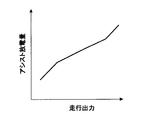
- FIG. 10 is a diagram illustrating a method for calculating the assist discharge amount.
- FIG. 11 is a diagram conceptually illustrating an example of a map of the assist discharge amount in a modification of the first embodiment.
- FIG. 12 is a diagram illustrating a schematic configuration of a control system for a hybrid vehicle according to a second embodiment.
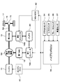
- FIG. 13 is a diagram illustrating a schematic configuration of a control system for a hybrid vehicle according to a third embodiment.
- Example 1 of the present disclosure will be described with reference to FIGS.
- a hot water circuit 25 for heating is connected to a cooling water passage (water jacket) of the engine 11.
- the warm water circuit 25 is provided with a heater core 26 for heating and an electric water pump 27.
- This electric water pump 27 circulates cooling water (hot water) between the engine 11 and the heater core 26.
- a blower fan 28 that generates warm air is disposed in the vicinity of the heater core 26.
- the electric air conditioner 24 includes an electric compressor 29, an accumulator 30, an outdoor heat exchanger 31, an expansion valve 32, an indoor heat exchanger 33, and the like. Electric power is supplied from the high-voltage battery 20 to the electric compressor 29.
- the accelerator sensor 34 detects the amount of operation of the accelerator pedal, which is the accelerator opening.
- An operating position of the shift lever is detected by the shift switch 35.
- a brake operation (or a brake operation amount by a brake sensor) is detected by the brake switch 36.
- the vehicle speed is detected by the vehicle speed sensor 37.
- the temperature of the high voltage battery 20 is detected by the battery temperature sensor 38.
- the hybrid ECU 39 is a control device that comprehensively controls the entire vehicle, and detects the driving state of the vehicle by reading the output signals of the various sensors and switches described above.
- the hybrid ECU 39 transmits and receives control signals, data signals, and the like among the engine ECU 40, the AT-ECU 41, the MG-ECU 42, and the air conditioner ECU 43.
- the hybrid ECU 39 is a vehicle control device.
- the hybrid ECU 39 controls the engine 11, the transmission 14, the MGs 12 and 13, the DC-DC converter 21, the hot water heater 23, the electric air conditioner 24, and the like according to the driving state of the vehicle by the ECUs 40 to 43. Further, the hybrid ECU 39 transmits and receives control signals and data signals to and from the power supply ECU 44 that monitors the high-voltage battery 20 and the navigation device 45.
- the hybrid ECU 39 switches the travel mode between, for example, an engine travel mode, an assist travel mode, and an EV travel mode.
- engine running mode engine running is performed in which the vehicle 17 is driven by driving the wheels 17 only with the power of the engine 11.
- assist travel is performed in which the vehicle 17 travels by driving the wheels 17 with both the power of the engine 11 and the power of the second MG 13 or the MGs 12 and 13.
- EV traveling mode EV traveling is performed in which the vehicle is driven by driving the wheels 17 with only the power of the second MG 13 or the MGs 12 and 13.
- the hybrid ECU 39 switches the traveling mode to the regenerative power generation mode when braking the vehicle (for example, when generating a braking force when the accelerator is off or the brake is on).
- the second MG 13 or MG 12, 13 is driven by the power of the wheels 17, and regenerative power generation is performed to convert the kinetic energy of the vehicle into electric energy by the second MG 13 or MG 12, 13, which is the generated power.
- Regenerative power is charged to the high voltage battery 20.
- the SOC indicating the remaining capacity of the high-voltage battery 20 reaches an upper limit value, and there is a possibility that the high-voltage battery 20 is in a saturated state where regenerative power cannot be charged.
- the following control is performed by executing the routines of FIGS. 4 to 6 by the hybrid ECU 39. I do.
- the predicted SOC that is the SOC in the planned travel route is predicted based on the prediction result of the road gradient and the vehicle speed in the planned travel route of the vehicle.
- the high voltage battery 20 is preliminarily set so that the high voltage battery 20 is not saturated based on the predicted SOC (that is, the SOC does not reach the upper limit value).
- Discharge increase control for increasing the discharge amount is executed. At that time, the discharge amount of the high-voltage battery 20 is increased by EV discharge so that the discharge of the high-voltage battery 20 is performed by assist discharge or EV traveling by assist travel.
- the hybrid ECU 39 includes a road gradient prediction unit 46, a vehicle speed prediction unit 47, a travel output calculation unit 48, a battery output calculation unit 49, an SOC prediction unit 50, a discharge amount calculation unit 51, and a discharge control. Part 52.
- the vehicle speed prediction unit 47 travels based on own vehicle position information, travel route information, speed limit information from a navigation device, a locator, etc., traffic information from an advanced driving support system, weather information, surrounding information, etc. Predict the behavior of the vehicle speed up to a predetermined distance ahead on the planned route.
- the travel output calculation unit 48 calculates or predicts the behavior of the travel output up to a predetermined distance ahead on the planned travel route based on the prediction result of the road gradient and the vehicle speed on the planned travel route.
- the battery output calculation unit 49 calculates or predicts the behavior of charge / discharge power, which is the output of the high-voltage battery 20 up to a predetermined distance ahead in the planned travel route, based on the calculation result of the travel output in the planned travel route.
- a travel mode change pattern which is a travel pattern on the planned travel route, is predicted based on the behavior of the travel output on the planned travel route.
- the output of the high-voltage battery 20 is calculated based on the output (for example, generated power) of the MGs 12 and 13 during engine travel and the power consumption of the auxiliary device (for example, the electric compressor 29).
- the output of the high voltage battery 20 is calculated based on the outputs (for example, power consumption) of the MGs 12 and 13 during assist travel and the power consumption of the auxiliary machine.
- the output of the high voltage battery 20 is calculated based on the outputs (for example, power consumption) of the MGs 12 and 13 during EV travel, the power consumption of the auxiliary machine, and the like.
- the output of the high voltage battery 20 is calculated based on the outputs (for example, generated power) of the MGs 12 and 13 during the regenerative power generation and the power consumption of the auxiliary machine.
- the regenerative power generation amount exceeding the upper limit value based on the predicted SOC behavior (for example, the total value of the regenerative power amount predicted to be able to be charged if it is not saturated) ) Is calculated as the predicted SOC excess amount.
- the discharge amount calculation unit 51 based on the predicted SOC excess amount, the discharge amount of the high-voltage battery 20 by the assist discharge that is the assist discharge amount for the discharge increase control in the scheduled travel route or the EV discharge that is the EV discharge amount
- the amount of discharge of the high voltage battery 20 is calculated.
- the behavior of the predicted SOC when the discharge increase control is executed reaches the upper limit value based on the behavior of the first predicted SOC that is the predicted SOC when the discharge increase control is not executed.
- an assist discharge amount and an EV discharge amount for discharge increase control are set.
- the behavior of the output of the high-voltage battery 20 changes between when the discharge increase control is not executed and when the discharge increase control is executed, but the output of the engine 11 is set so that the traveling output is substantially the same. It ’s fine.
- the assist discharge amount and EV discharge amount are set so that the amount of electric power exceeding the predicted SOC excess amount is consumed in the assist discharge and EV discharge before the start of regenerative power generation that is predicted to reach the upper limit value first. You may make it do.
- the assist discharge amount or EV discharge amount may be set so that the amount of electric power exceeding the predicted SOC excess amount is consumed in the assist discharge or EV discharge. Further, the assist traveling period and the EV traveling period may be lengthened.
- the discharge controller 52 controls the engine 11, the MGs 12 and 13, etc. so as to realize the assist discharge amount and EV discharge amount for the discharge increase control in the planned travel route, thereby reducing the discharge amount of the high-voltage battery 20.
- the discharge increase control to be increased is executed.
- the main control routine shown in FIG. 4 is repeatedly executed at a predetermined cycle during the power-on period of the hybrid ECU 39.
- this routine is started, first, at 101, it is determined whether it is difficult to predict the planned travel route. In this case, when the destination information of the vehicle is not obtained and the number of route branches in the traveling direction is greater than or equal to a predetermined value (for example, 1 or 2), it is determined that the predicted travel route is difficult to predict.
- a predetermined value for example, 1 or 2
- FIG. 7A if there is destination information, it is possible to predict a planned travel route even if there is a route branch in the traveling direction. Further, as shown in FIG. 7B, even if there is no destination information, the planned travel route can be predicted if there are no or few route branches in the traveling direction. Therefore, as shown in FIG. 7C, when the destination information is not obtained and the number of route branches in the traveling direction is equal to or greater than a predetermined value, it can be determined that it is difficult to predict the planned travel route.
- the charge amount (for example, charge) of the high voltage battery 20 is referred to with reference to the map of fuel consumption maximization charge / discharge amount shown in FIG. Power) or discharge amount (for example, discharge power) is set.
- the hybrid ECU 39 controls the engine 11, the MGs 12, 13 and the like so as to realize this charge amount or discharge amount.
- the process proceeds to 102.
- Whether or not the high voltage battery 20 has deteriorated is determined based on at least one of the temperature, voltage, internal resistance, etc. Judgment.
- the process proceeds to 112, and discharge increase control is prohibited.
- the processes 102 and 112 serve as a second prohibition unit. Thereafter, the process proceeds to 113, and the fuel consumption maximizing charge / discharge amount is set.
- the process proceeds to 103 and the actual SOC of the high voltage battery 20 is measured.
- the process proceeds to 114, where the charge amount (for example, charge power) of the high-voltage battery 20 is set to the sum of the power consumption of the auxiliary machines including the electric compressor 29. .
- the charge amount (for example, charge power) of the high-voltage battery 20 is set to the sum of the power consumption of the auxiliary machines including the electric compressor 29. .
- the power generation amount (for example, power generation power) of the first MG 12 or the MGs 12 and 13 is the total power consumption of the auxiliary machine including the electric compressor 29 that is the charge amount of the high-voltage battery 20.
- the processes 104 and 114 serve as an SOC reduction suppressing unit.
- the predicted SOC behavior deviates from the actual SOC behavior. It is determined whether or not.
- the processing proceeds to 106.
- a change in the travel route it is determined whether or not a change in the travel route has occurred.
- the travel route is changed, the road gradient, the vehicle speed, etc. change, and the change pattern of the travel mode, which is the travel output and travel pattern, changes, so the output of the high voltage battery 20 changes and the behavior of the SOC changes. To do. Therefore, the change of the travel route becomes a cause of SOC shift.
- the SOC deviation factor is vehicle control in which the predicted SOC behavior is expected to deviate from the actual SOC behavior.
- step 107 it is determined whether or not a change in the operating state of auxiliary equipment such as the electric air conditioner 24 and lights (for example, switch-on or switch-off) has occurred.
- auxiliary equipment such as the electric air conditioner 24 and lights (for example, switch-on or switch-off)
- the SOC deviation factor is vehicle control in which the predicted SOC behavior is expected to deviate from the actual SOC behavior.
- the process proceeds to 109.
- a change in road surface condition for example, road surface wetness due to rain, road surface snow accumulation due to snowfall, road surface freezing due to temperature drop, etc.
- the SOC deviation factor is an environmental change in which the behavior of the predicted SOC is expected to deviate from the actual behavior of the SOC.
- the process proceeds to 203, and the behavior of the road gradient up to a predetermined distance ahead in the planned travel route is predicted based on the vehicle position information, the planned travel route, and the like. Thereafter, the process proceeds to 204, where the behavior of the vehicle speed up to a predetermined distance on the planned travel route is predicted based on the vehicle position information, the planned travel route, the speed limit information, the traffic information, the weather information, the peripheral information, and the like.
- the process 203 serves as a road gradient prediction unit
- the process 204 serves as a vehicle speed prediction unit.
- the process proceeds to 205, and the behavior of the travel output up to a predetermined distance ahead on the planned travel route is calculated based on the prediction result of the road gradient and the vehicle speed. Based on the calculation result of the travel output, the behavior of charge / discharge power, which is the output of the high voltage battery 20 up to a predetermined distance ahead in the planned travel route, is calculated. Based on the calculation result of the output of the high-voltage battery 20, the SOC behavior up to a predetermined distance ahead in the planned travel route is predicted. In the present embodiment, the process 205 serves as an SOC prediction unit.
- routine proceeds to 206, where it is determined whether or not the high voltage battery 20 is saturated so that the regenerative power cannot be charged, depending on whether or not the predicted SOC reaches the upper limit value.
- the routine proceeds to 207, where the fuel consumption maximizing charge / discharge amount setting (the same processing as 113 in FIG. 4) is performed. )I do.
- step 208 based on the predicted SOC excess amount, an assist discharge amount and an EV discharge amount for discharge increase control in the planned travel route are calculated. For example, when the discharge increase control is performed only by the assist discharge, the assist discharge amount calculation routine of FIG. 6 is executed at 208 to calculate the assist discharge amount for the discharge increase control.
- the processes 206 and 208 serve as a discharge control unit, and in the present embodiment, the processes 201 to 208 serve as a correction unit.
- the predicted SOC excess amount is calculated.
- the behavior of the predicted SOC excess amount up to a predetermined distance ahead in the planned travel route is calculated based on the behavior of the predicted SOC up to a predetermined distance ahead in the planned travel route.
- the process proceeds to 302 to calculate the predicted engine operation time.
- the behavior of the predicted engine operation time up to the predetermined distance ahead on the planned travel route is calculated based on the behavior of the predicted engine operation state up to the predetermined distance ahead on the planned travel route. .
- the process proceeds to 303 to calculate the assist discharge amount.
- the assist discharge amount is obtained by dividing the predicted SOC excess amount by the predicted engine operation time for each distance on the planned travel route, and the maximum value is determined as the final assist discharge amount.
- the command assist discharge amount is By controlling the engine 11 and the MGs 12 and 13 so as to realize this assist discharge amount, discharge increase control for increasing the discharge amount of the high-voltage battery 20 is executed.
- the SOC in the planned travel route is predicted based on the prediction result of the road gradient and the vehicle speed in the planned travel route of the vehicle.
- discharge increase control is executed to increase the discharge amount of the high voltage battery 20 in advance so that the high voltage battery 20 is not saturated based on the predicted SOC. . Accordingly, if the predicted SOC is correct, the high voltage battery 20 can be prevented from being saturated by controlling the SOC not to reach the upper limit value by the discharge increase control based on the predicted SOC.
- the discharge increase control it is determined whether or not the predicted SOC behavior is deviated from the actual SOC behavior or whether an SOC deviation factor has occurred.
- the prediction of the SOC on the planned travel route is performed again. Correct the discharge increase control. Thereby, even when the behavior of the predicted SOC is deviated from the actual behavior of the SOC, the predicted SOC can be corrected by performing the prediction of the SOC again.
- the discharge increase control is corrected based on the corrected predicted SOC, and the corrected discharge increase control is performed so that the SOC does not reach the upper limit value, thereby preventing the high voltage battery 20 from being saturated. can do. Thereby, it is possible to reliably prevent the high-voltage battery 20 from being saturated, to effectively use the regenerative power generation, and to effectively improve fuel efficiency.
- the SOC that is obtained by subtracting the increase in the amount of discharge due to the discharge increase control from the predicted time point of the predicted SOC to the current time from the predicted SOC of the current time when the discharge increase control is not executed is used as the discharge increase control. Obtained as the predicted SOC of the local point when executed.
- the difference between the predicted SOC at the local point when this discharge increase control is executed and the actual SOC at the local point is a predetermined value or more, the behavior of the predicted SOC is deviated from the actual SOC behavior. judge. In this way, it is possible to accurately determine that the behavior of the predicted SOC is deviated from the actual behavior of the SOC by comparing the predicted SOC when the discharge increase control is executed with the actual SOC. it can.
- the first MG 12 or MG 12, 13 when the actual SOC becomes a predetermined value or less, discharging of the high voltage battery 20 is prohibited, and the first MG 12 or MG 12, 13 is rotated by the power of the engine 11 to drive the first MG 12 or MG 12. , 13 generates electricity. If it does in this way, the excessive fall of SOC can be controlled.
- the discharge increase control is prohibited. Thereby, deterioration of the fuel consumption by the discharge increase control based on the uncertain predicted SOC can be prevented.
- the discharge increase control is prohibited when the high voltage battery 20 is deteriorated (that is, the deterioration state of the high voltage battery 20 is not less than a predetermined value).
- the discharge amount of the high voltage battery 20 is increased by the assist discharge for discharging the high voltage battery 20 by the assist traveling or the EV discharge for discharging the high voltage battery 20 by the EV traveling. Let If it does in this way, the amount of discharges of high voltage battery 20 can be increased, converting the electric power of high voltage battery 20 into the driving force of vehicles by assist discharge or EV discharge, and using effectively.
- the discharge amount of the high-voltage battery 20 may be increased by both the assist discharge and the EV discharge. However, the discharge amount of the high-voltage battery 20 by only one of the assist discharge and the EV discharge. May be increased.
- the assist discharge amount corresponding to the travel output of the vehicle is calculated with reference to the assist discharge amount map shown in FIG.
- the assist discharge amount map is set so that the assist discharge amount increases as the traveling output of the vehicle increases, and the assist discharge amount decreases as the traveling output of the vehicle decreases.
- the engine 11 can be used in a region where the efficiency of the engine 11 is high without reducing the output of the engine 11 and the fuel efficiency is high. Can drive.
- the traveling output of the vehicle is large, even if the assist discharge power is increased, the output of the engine 11 can be increased and the engine can be operated in a region where the efficiency of the engine 11 is high.
- Example 2 of the present disclosure will be described with reference to FIG.
- parts that are substantially the same as or similar to those in the first embodiment are denoted by the same reference numerals, and description thereof is omitted or simplified, and parts that are different from those in the first embodiment are mainly described.
- the clutch is not provided in the power transmission path from the engine 11 to the transmission 14, but the present invention is not limited to this.
- a clutch is provided between the engine 11 and the MG 12, or the MG 12 and the transmission are changed.
- a clutch may be provided between the machine 14 and the machine 14.
- a clutch may be built in the transmission 14. Further, the transmission 14 may be omitted.
- this indication is not limited to the hybrid vehicle of the structure shown to FIG.1, FIG.12, FIG.13, It can implement by applying to the hybrid vehicle of the various structures carrying an engine and MG as a motive power source of a vehicle.
- the method of determining whether or not the behavior of the predicted SOC is deviated from the actual behavior of the SOC is not limited to the method described in the above embodiment, and may be changed as appropriate.
- the difference between the current predicted SOC when the discharge increase control is not executed and the SOC obtained by adding the increase in discharge amount by the discharge increase control from the predicted time point of the predicted SOC to the current time to the actual SOC at the local point is a predetermined value. In the above case, it may be determined that the behavior of the predicted SOC is deviated from the actual behavior of the SOC.
- the present invention is not limited to this, and whether or not other vehicle control (unpredicted stopping, sudden acceleration, sudden deceleration, etc.) or environmental change (for example, change in temperature, atmospheric pressure, etc.) has occurred as a cause of SOC deviation. It may be determined.
- the function of generating electric power by rotating the MG with the power of the engine by prohibiting the discharge of the high voltage battery, and the discharge increase control when it is difficult to predict the planned travel route At least one of a function for prohibiting discharge and a function for prohibiting discharge increase control when the deterioration state of the battery is greater than or equal to a predetermined value may be omitted.
- the discharge amount of the high voltage battery is increased by assist discharge or EV discharge in the discharge increase control.
- the discharge amount of the high voltage battery may be increased by other methods. .
Landscapes
- Engineering & Computer Science (AREA)
- Transportation (AREA)
- Mechanical Engineering (AREA)
- Chemical & Material Sciences (AREA)
- Combustion & Propulsion (AREA)
- Power Engineering (AREA)
- Sustainable Energy (AREA)
- Sustainable Development (AREA)
- Life Sciences & Earth Sciences (AREA)
- Automation & Control Theory (AREA)
- Mathematical Physics (AREA)
- Physics & Mathematics (AREA)
- Theoretical Computer Science (AREA)
- General Engineering & Computer Science (AREA)
- Computational Linguistics (AREA)
- Software Systems (AREA)
- General Physics & Mathematics (AREA)
- Computing Systems (AREA)
- Evolutionary Computation (AREA)
- Data Mining & Analysis (AREA)
- Artificial Intelligence (AREA)
- Hybrid Electric Vehicles (AREA)
- Electric Propulsion And Braking For Vehicles (AREA)
Abstract
車両の制御装置は、車両の動力源となるエンジン(11)及びモータジェネレータ(12、13)と、モータジェネレータと電力を授受するバッテリ(20)とを備え、車両を制動する際にモータジェネレータで回生発電した電力である回生電力をバッテリに充電する車両の制御装置において、車両の走行予定経路における道路勾配及び車速の予測結果に基づいて走行予定経路におけるバッテリの残容量を表すSOCを予測するSOC予測部(39、50、205)と、SOC予測部で予測したSOCである予測SOCに基づいてバッテリが回生電力を充電できない飽和状態になると判定した場合に、予測SOCに基づいてバッテリが飽和状態にならないように予めバッテリの放電量を増加させる放電増加制御を実行する放電制御部(39、52、206、208、301~303)と、放電増加制御の開始後に、予測SOCの挙動が実際のSOCの挙動に対してずれているか又は予測SOCの挙動が実際のSOCの挙動に対してずれると予想される車両制御又は環境変化であるSOCずれ要因が発生したか否かを判定する判定部(39、105~109)と、判定部で予測SOCの挙動が実際のSOCの挙動に対してずれていると判定された場合又はSOCずれ要因が発生したと判定された場合に、走行予定経路におけるSOCの予測を再度実施して放電増加制御を修正する修正部(39、110、201~209、301~303)とを備えている。
Description
本出願は、2015年11月6日に出願された日本特許出願番号2015-218983号に基づくもので、ここにその記載内容を援用する。
本開示は、車両の動力源となるエンジン及びモータジェネレータを備えた車両の制御装置に関するものである。
近年、低燃費、低排気エミッションの社会的要請から車両の動力源としてエンジンとモータジェネレータ(MG)とを搭載したハイブリッド車が注目されている。このハイブリッド車においては、車両を制動する際にMGで回生発電した電力(回生電力)をバッテリに充電することで、MGの動力を使うアシスト走行やEV走行の実施可能時間を長くして燃費を向上させる。
しかし、長い下り坂で回生発電し続けると、バッテリの残容量を表すSOCが上限値に到達してバッテリが回生電力を充電できない飽和状態になってしまう可能性ある。
そこで、特許文献1に記載されているように、ナビゲーション装置からの道路情報に基づいて、下り走行工程直前までの走行工程でバッテリを中間領域以下の残容量まで放電させる深放電制御を行う。
本発明者は、バッテリが回生電力を充電できない飽和状態になることを防止するために、次のようなシステムを研究している。車両の走行予定経路における道路勾配や車速の予測結果に基づいて走行予定経路におけるSOCである予測SOCを予測する。その予測SOCに基づいてバッテリが飽和状態になると判定または予測した場合に、予測SOCに基づいてバッテリが飽和状態にならない(つまりSOCが上限値に到達しない)ように予めバッテリの放電量を増加させる放電増加制御を実行する。しかし、その研究過程で次のような新たな課題が判明した。
予測SOCの挙動が実際のSOCの挙動に対してずれると、予測SOCに基づいた放電増加制御を実行しても、SOCを適正に制御できず、バッテリが飽和状態になってしまう可能性がある。その結果、回生発電を有効利用することができず、燃費を効果的に向上させることができなくなる可能性がある。
本開示の目的は、バッテリが飽和状態になることを確実に防止して、回生発電を有効利用することができ、燃費を効果的に向上させることができる車両の制御装置を提供することにある。
本開示の一態様による車両の制御装置は、車両の動力源となるエンジン及びモータジェネレータと、モータジェネレータと電力を授受するバッテリとを備え、車両を制動する際にモータジェネレータで回生発電した電力である回生電力をバッテリに充電する車両の制御装置において、車両の走行予定経路における道路勾配及び車速の予測結果に基づいて走行予定経路におけるバッテリの残容量を表すSOCを予測するSOC予測部と、SOC予測部で予測したSOCである予測SOCに基づいてバッテリが回生電力を充電できない飽和状態になると判定した場合に、予測SOCに基づいてバッテリが飽和状態にならないように予めバッテリの放電量を増加させる放電増加制御を実行する放電制御部と、放電増加制御の開始後に、予測SOCの挙動が実際のSOCの挙動に対してずれているか又は予測SOCの挙動が実際のSOCの挙動に対してずれると予想される車両制御又は環境変化であるSOCずれ要因が発生したか否かを判定する判定部と、判定部で予測SOCの挙動が実際のSOCの挙動に対してずれていると判定された場合又はSOCずれ要因が発生したと判定された場合に、走行予定経路におけるSOCの予測を再度実施して放電増加制御を修正する修正部とを備える。
この構成では、車両の走行予定経路における道路勾配及び車速の予測結果に基づいて走行予定経路におけるSOCである予測SOCを予測する。その予測SOCに基づいてバッテリが飽和状態になると判定または予測した場合に、予測SOCに基づいてバッテリが飽和状態にならない(つまりSOCが上限値に到達しない)ように予めバッテリの放電量を増加させる放電増加制御を実行する。これにより、予測SOCが正しければ、予測SOCに基づいた放電増加制御により、SOCが上限値に到達しないように制御して、バッテリが飽和状態になることを防止することができる。
しかし、予測SOCの挙動が実際のSOCの挙動に対してずれると、予測SOCに基づいた放電増加制御を実行しても、SOCを適正に制御できず、バッテリが飽和状態になってしまう可能性がある。
この対策として、放電増加制御の開始後に、予測SOCの挙動が実際のSOCの挙動に対してずれているか又はSOCずれ要因が発生したか否かを判定し、予測SOCの挙動が実際のSOCの挙動に対してずれていると判定された場合又はSOCずれ要因が発生したと判定された場合に、走行予定経路におけるSOCの予測を再度実施して放電増加制御を修正する。これにより、予測SOCの挙動が実際のSOCの挙動に対してずれる場合でも、SOCの予測を再度実施することで予測SOCを修正することができる。更に、修正後の予測SOCに基づいて放電増加制御を修正して、修正後の放電増加制御により、SOCが上限値に到達しないように制御して、バッテリが飽和状態になることを防止することができる。これにより、バッテリが飽和状態になることを確実に防止して、回生発電を有効利用することができ、燃費を効果的に向上させることができる。
本開示についての上記目的およびその他の目的、特徴や利点は、添付の図面を参照しながら下記の詳細な記述により、より明確になる。その図面は、
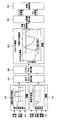
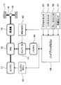
図1は本開示の実施例1におけるハイブリッド車の制御システムの概略構成を示す図であり、
図2はSOC予測及び放電増加制御の機能を示すブロック図であり、
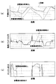
図3は予測SOCと高圧バッテリ出力とエンジン出力の挙動を示すタイムチャートであり、
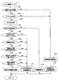
図4はメイン制御ルーチンの処理の流れを示すフローチャートであり、
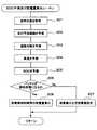
図5はSOC予測及び放電量算出ルーチンの処理の流れを示すフローチャートであり、
図6はアシスト放電量算出ルーチンの処理の流れを示すフローチャートであり、
図7は経路予測が困難か否かの判定方法を説明する図であり、
図8は燃費最大化充放電量のマップの一例を概念的に示す図であり、
図9は予測SOCの挙動が実際のSOCの挙動に対してずれているか否かの判定方法を説明する図であり、
図10はアシスト放電量の算出方法を説明する図であり、
図11は実施例1の変形例におけるアシスト放電量のマップの一例を概念的に示す図であり、
図12は実施例2のハイブリッド車の制御システムの概略構成を示す図であり、
図13は実施例3のハイブリッド車の制御システムの概略構成を示す図である。
以下、本開示を実施するための形態を具体化した幾つかの実施例を説明する。
本開示の実施例1を図1乃至図11に基づいて説明する。
まず、図1に基づいてハイブリッド車の制御システムの概略構成を説明する。
車両の動力源として内燃機関であるエンジン11と第1モータジェネレータ(第1MG)12と第2モータジェネレータ(第2MG)13とが搭載されている。エンジン11の出力軸であるクランク軸の動力がMG12,13を介して変速機14に伝達される。この変速機14の出力軸の動力がデファレンシャルギヤ機構15や車軸16等を介して車輪17である駆動輪に伝達される。変速機14は、複数段の変速段の中から変速段を段階的に切り換える有段変速機であっても良いし、無段階に変速する無段変速機(CVT)であっても良い。第1MG12と第2MG13との間には、動力伝達を断続するためのクラッチ18が設けられている。
また、MG12,13を駆動するインバータ19が高圧バッテリ20に接続され、MG12,13がインバータ19を介して高圧バッテリ20と電力を授受する。高圧バッテリ20には、DC-DCコンバータ21を介して低圧バッテリ22が接続されている。高圧バッテリ20と低圧バッテリ22は、いずれも充放電可能なバッテリである。更に、DC-DCコンバータ21には、高圧バッテリ20からDC-DCコンバータ21を介して供給される電力又は低圧バッテリ22から供給される電力を消費する低圧負荷が接続されている。この低圧負荷は、例えば、電動ウォータポンプ27、ブロアファン28等である。
また、エンジン11の冷却水の熱を利用する温水暖房装置23と、電気で冷暖房する電気空調装置24(例えばヒートポンプ装置)とが搭載されている。
温水暖房装置23は、エンジン11の冷却水通路(ウォータジャケット)に、暖房用の温水回路25が接続されている。この温水回路25に、暖房用のヒータコア26と電動ウォータポンプ27が設けられている。この電動ウォータポンプ27によりエンジン11とヒータコア26との間で冷却水(温水)を循環させる。ヒータコア26の近傍には、温風を発生させるブロアファン28が配置されている。
電気空調装置24は、電動コンプレッサ29、アキュムレータ30、室外熱交換器31、膨張弁32、室内熱交換器33等から構成されている。電動コンプレッサ29には、高圧バッテリ20から電力が供給される。
また、アクセルセンサ34によってアクセル開度であるアクセルペダルの操作量が検出される。シフトスイッチ35によってシフトレバーの操作位置が検出される。ブレーキスイッチ36によってブレーキ操作(又はブレーキセンサによってブレーキ操作量)が検出される。車速センサ37によって車速が検出される。バッテリ温度センサ38によって高圧バッテリ20の温度が検出される。
ハイブリッドECU39は、車両全体を総合的に制御する制御装置であり、上述した各種のセンサやスイッチの出力信号を読み込んで、車両の運転状態を検出する。このハイブリッドECU39は、エンジンECU40とAT-ECU41とMG-ECU42とエアコンECU43との間で制御信号やデータ信号等を送受信する。本実施形態では、ハイブリッドECU39は、車両の制御装置である。
エンジンECU40は、エンジン11の運転を制御する制御装置である。AT-ECU41は、変速機14を制御する制御装置である。MG-ECU42は、インバータ19を制御してMG12,13を制御すると共にDC-DCコンバータ21を制御する制御装置である。エアコンECU43は、温水暖房装置23及び電気空調装置24(例えば電動ウォータポンプ27、ブロアファン28、電動コンプレッサ29等)を制御する制御装置である。
ハイブリッドECU39は、各ECU40~43によって車両の運転状態に応じて、エンジン11、変速機14、MG12,13、DC-DCコンバータ21、温水暖房装置23、電気空調装置24等を制御する。更に、ハイブリッドECU39は、高圧バッテリ20を監視する電源ECU44や、ナビゲーション装置45との間でも制御信号やデータ信号等を送受信する。
その際、ハイブリッドECU39は、走行モードを、例えば、エンジン走行モードとアシスト走行モードとEV走行モードとの間で切り換える。エンジン走行モードでは、エンジン11の動力のみで車輪17を駆動して車両を走行させるエンジン走行を行う。アシスト走行モードでは、エンジン11の動力と第2MG13又はMG12,13の動力の両方で車輪17を駆動して車両を走行させるアシスト走行を行う。EV走行モードでは、第2MG13又はMG12,13の動力のみで車輪17を駆動して車両を走行させるEV走行を行う。
また、ハイブリッドECU39は、車両を制動する際(例えばアクセルオフ時やブレーキオン時に制動力を発生させる際)に、走行モードを回生発電モードに切り換える。この回生発電モードでは、車輪17の動力で第2MG13又はMG12,13を駆動することで、車両の運動エネルギを第2MG13又はMG12,13で電気エネルギに変換する回生発電を行い、その発電電力である回生電力を高圧バッテリ20に充電する。これにより、アシスト走行やEV走行の実施可能時間を長くして燃費を向上させることができる。
しかし、長い下り坂で回生発電し続けると、高圧バッテリ20の残容量を表すSOCが上限値に到達して高圧バッテリ20が回生電力を充電できない飽和状態になってしまう可能性ある。SOCは、例えば、次式により定義される。
SOC=残容量/満充電容量×100
SOC=残容量/満充電容量×100
そこで、本実施例1では、高圧バッテリ20が回生電力を充電できない飽和状態になることを防止するために、ハイブリッドECU39により図4乃至図6の各ルーチンを実行することで、次のような制御を行う。
車両の走行予定経路における道路勾配及び車速の予測結果に基づいて走行予定経路におけるSOCである予測SOCを予測する。予測SOCに基づいて高圧バッテリ20が飽和状態になると判定または予測した場合に、予測SOCに基づいて高圧バッテリ20が飽和状態にならない(つまりSOCが上限値に到達しない)ように予め高圧バッテリ20の放電量を増加させる放電増加制御を実行する。その際、アシスト走行により高圧バッテリ20の放電を行うアシスト放電やEV走行により高圧バッテリ20の放電を行うようにEV放電で高圧バッテリ20の放電量を増加させる。これにより、予測SOCが正しければ、予測SOCに基づいた放電増加制御により、SOCが上限値に到達しないように制御して、高圧バッテリ20が飽和状態になることを防止することができる。本実施形態では、ハイブリッドECU39は道路勾配予測部46と、車速予測部47と、走行出力算出部48と、バッテリ出力算出部49と、SOC予測部50と、放電量算出部51と、放電制御部52とを有する。
具体的には、図2に示すように、まず、道路勾配予測部46で、ナビゲーション装置45やロケータ等からの自車位置情報、走行経路情報等に基づいて、走行予定経路における所定距離先(例えば10km先)までの道路勾配の挙動を予測する。
また、車速予測部47で、ナビゲーション装置やロケータ等からの自車位置情報、走行経路情報、制限速度情報や、高度運転支援システム等からの交通情報、気象情報、周辺情報等に基づいて、走行予定経路における所定距離先までの車速の挙動を予測する。
この後、走行出力算出部48で、走行予定経路における道路勾配及び車速の予測結果に基づいて、走行予定経路における所定距離先までの走行出力の挙動を算出または予測する。
この後、バッテリ出力算出部49で、走行予定経路における走行出力の算出結果に基づいて、走行予定経路における所定距離先までの高圧バッテリ20の出力である充放電電力の挙動を算出または予測する。この場合、例えば、走行予定経路における走行出力の挙動に基づいて、走行予定経路における走行パターンである走行モードの変化パターンを予測する。エンジン走行モードでは、エンジン走行時のMG12,13の出力(例えば発電電力)と補機(例えば電動コンプレッサ29等)の消費電力等に基づいて高圧バッテリ20の出力を算出する。アシスト走行モードでは、アシスト走行時のMG12,13の出力(例えば消費電力)と補機の消費電力等に基づいて高圧バッテリ20の出力を算出する。EV走行モードでは、EV走行時のMG12,13の出力(例えば消費電力)と補機の消費電力等に基づいて高圧バッテリ20の出力を算出する。回生発電モードでは、回生発電時のMG12,13の出力(例えば発電電力)と補機の消費電力等に基づいて高圧バッテリ20の出力を算出する。
この後、SOC予測部50で、走行予定経路における高圧バッテリ20の出力の算出結果に基づいて、走行予定経路における所定距離先までのSOCの挙動を予測する。その予測SOCが上限値(例えば満充電状態又はそれに近い状態に相当する値)に到達するか否かによって、高圧バッテリ20が回生電力を充電できない飽和状態になるか否かを判定する。高圧バッテリ20が飽和状態になると判定した場合には、予測SOCの挙動に基づいて、上限値を越える分の回生発電量(例えば飽和状態でなければ充電できると予測される回生電力量の合計値)を予測SOC超過量として算出する。
この後、放電量算出部51で、予測SOC超過量に基づいて、走行予定経路における放電増加制御用のアシスト放電量であるアシスト放電による高圧バッテリ20の放電量やEV放電量であるEV放電による高圧バッテリ20の放電量を算出する。この場合、例えば、図3に示すように、放電増加制御を実行しない場合の予測SOCである最初予測SOCの挙動に基づいて、放電増加制御を実行した場合の予測SOCの挙動が上限値に到達しないように、放電増加制御用のアシスト放電量やEV放電量を設定する。この際、放電増加制御を実行しない場合と放電増加制御を実行した場合とで、高圧バッテリ20の出力の挙動が変化するが、走行出力がほぼ同じになるように、エンジン11の出力を設定すれば良い。また、予測SOCが最初に上限値に到達すると予測される回生発電の開始前までのアシスト放電やEV放電で予測SOC超過量以上の電力量を消費するようにアシスト放電量やEV放電量を設定するようにしても良い。或は、予測SOCが最初に上限値に到達すると予測される回生発電の開始前までのアシスト放電やEV放電と、予測SOCが2回目以降に上限値に到達すると予測される回生発電の開始前のアシスト放電やEV放電で、予測SOC超過量以上の電力量を消費するようにアシスト放電量やEV放電量を設定するようにしても良い。また、アシスト走行の期間やEV走行の期間を長くするようにしても良い。
この後、放電制御部52で、走行予定経路における放電増加制御用のアシスト放電量やEV放電量を実現するようにエンジン11やMG12,13等を制御することで、高圧バッテリ20の放電量を増加させる放電増加制御を実行する。
しかし、予測SOCの挙動が実際のSOCの挙動に対してずれると、予測SOCに基づいた放電増加制御を実行しても、SOCを適正に制御できず、高圧バッテリ20が飽和状態になってしまう可能性がある。
この対策として、放電増加制御の開始後に、予測SOCの挙動が実際のSOCの挙動に対してずれているか又は予測SOCの挙動が実際のSOCの挙動に対してずれると予想される車両制御又は環境変化であるSOCずれ要因が発生したか否かを判定する。その結果、予測SOCの挙動が実際のSOCの挙動に対してずれていると判定された場合又はSOCずれ要因が発生したと判定された場合に、走行予定経路におけるSOCの予測を再度実施して放電増加制御を修正する。これにより、予測SOCの挙動が実際のSOCの挙動に対してずれる場合でも、SOCの予測を再度実施することで予測SOCを修正することができる。更に、修正後の予測SOCに基づいて放電増加制御を修正して、修正後の放電増加制御により、SOCが上限値に到達しないように制御して、高圧バッテリ20が飽和状態になることを防止することができる。
以下、本実施例1でハイブリッドECU39が実行する図4乃至図6の各ルーチンの処理内容を説明する。
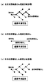
図4に示すメイン制御ルーチンは、ハイブリッドECU39の電源オン期間中に所定周期で繰り返し実行される。本ルーチンが起動されると、まず、101で、走行予定経路の予測が困難か否かを判定する。この場合、車両の目的地情報が得られず且つ進行方向の経路分岐数が所定値(例えば1又は2)以上の場合に、走行予定経路の予測が困難と判定する。
図7(a)に示すように、目的地情報があれば、進行方向の経路分岐があっても、走行予定経路を予測することができる。また、図7(b)に示すように、目的地情報がなくても、進行方向の経路分岐がないか又は少なければ、走行予定経路を予測することができる。従って、図7(c)に示すように、目的地情報が得られず且つ進行方向の経路分岐数が所定値以上の場合には、走行予定経路の予測が困難と判定することができる。
この101で、走行予定経路の予測が困難と判定された場合には、112に進み、放電増加制御を禁止する。この場合、101,112の処理が第1禁止部としての役割を果たす。
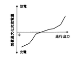
この後、113に進み、燃費最大化充放電量設定を行う。この燃費最大化充放電量設定では、図8に示す燃費最大化充放電量のマップを参照して、車両の走行出力に応じて燃費が最大となるように高圧バッテリ20の充電量(例えば充電電力)又は放電量(例えば放電電力)を設定する。ハイブリッドECU39は、この充電量又は放電量を実現するようにエンジン11やMG12,13等を制御する。
一方、上記101で、走行予定経路の予測が困難ではない(つまり走行予定経路を予測することができる)と判定された場合には、102に進む。この102で、高圧バッテリ20が劣化している(つまり高圧バッテリ20の劣化状態が所定以上)か否かを、例えば、高圧バッテリ20の温度、電圧、内部抵抗等のうちの少なくとも一つに基づいて判定する。
上記102で、高圧バッテリ20が劣化していると判定された場合には、112に進み、放電増加制御を禁止する。この場合、102,112の処理が第2禁止部としての役割を果たす。この後、113に進み、燃費最大化充放電量設定を行う。
一方、上記102で、高圧バッテリ20が劣化していないと判定された場合には、103に進み、高圧バッテリ20の実際のSOCを計測する。
この後、104に進み、実際のSOCが所定値(例えば許容下限値又はそれよりも少し高い値)以下か否かを判定する。
この104で、実際のSOCが所定値以下と判定された場合には、114に進み、高圧バッテリ20の充電量(例えば充電電力)を電動コンプレッサ29を含む補機の消費電力の総和に設定する。これにより、高圧バッテリ20の放電を禁止してエンジン11の動力で第1MG12又はMG12,13を回転駆動して第1MG12又はMG12,13で発電する。この際、第1MG12又はMG12,13の発電量(例えば発電電力)は、高圧バッテリ20の充電量である電動コンプレッサ29を含む補機の消費電力の総和とする。この場合、104,114の処理がSOC低下抑制部としての役割を果たす。
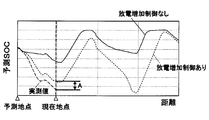
一方、上記104で、実際のSOCが所定値よりも高いと判定された場合には、105に進み、予測SOCの挙動が実際のSOCの挙動に対してずれているか否かを判定する。この場合、図9に示すように、放電増加制御を実行しない場合の現時点の予測SOCから、その予測SOCの予測時点から現時点までの放電増加制御による放電量増加分を差し引いたSOCを、放電増加制御を実行した場合の現地点の予測SOCとして求める。この放電増加制御を実行した場合の現地点の予測SOCと、現地点の実際のSOCとの差Aが所定値以上か否かによって、予測SOCの挙動が実際のSOCの挙動に対してずれているか否かを判定する。
尚、予測SOCの初期値は、この105で、予測SOCの挙動が実際のSOCの挙動に対してずれていると判定されるような値に設定されている。従って、本ルーチンの起動後に最初に105に進んだときには、この105で「Yes」と判定されて、110に進む。この110で、図5のSOC予測及び放電量算出ルーチンを実行することで、走行予定経路におけるSOCを予測し、その予測SOCに基づいて高圧バッテリ20が飽和状態になると判定した場合には、走行予定経路における放電増加制御用の放電量(例えば放電電力)を算出して放電増加制御を実行する。
その後、上記105で、予測SOCの挙動が実際のSOCの挙動に対してずれていないと判定された場合には、106に進む。この106で、走行経路の変更が発生したか否かを判定する。走行経路が変更されると、道路勾配や車速等が変化して、走行出力や走行パターンである走行モードの変化パターンが変化するため、高圧バッテリ20の出力が変化して、SOCの挙動が変化する。従って、走行経路の変更は、SOCずれ要因となる。この場合、SOCずれ要因は、予測SOCの挙動が実際のSOCの挙動に対してずれると予想される車両制御である。
上記106で、走行経路の変更が発生していないと判定された場合には、107に進む。この107で、電気空調装置24やライト等の補機の作動状態の変化(例えばスイッチオン又はスイッチオフ等)が発生したか否かを判定する。補機の作動状態が変化すると、補機の消費電力が変化するため、高圧バッテリ20の出力が変化して、SOCの挙動が変化する。従って、補機の作動状態の変化は、SOCずれ要因となる。この場合、SOCずれ要因は、予測SOCの挙動が実際のSOCの挙動に対してずれると予想される車両制御である。
上記107で、補機の作動状態の変化が発生していないと判定された場合には、108に進む。この108で、風速又は風向の変化が発生したか否かを判定する。風速や風向が変化すると、車速等が変化して、走行出力や走行パターンが変化するため、高圧バッテリ20の出力が変化して、SOCの挙動が変化する。従って、風速や風向の変化は、SOCずれ要因となる。この場合、SOCずれ要因は、予測SOCの挙動が実際のSOCの挙動に対してずれると予想される環境変化である。
上記108で、風速や風向の変化が発生していないと判定された場合には、109に進む。この109で、路面状態の変化(例えば、降雨による路面の濡れ、降雪による路面の積雪、温度低下による路面の凍結等)が発生したか否かを判定する。路面状態が変化すると、車速等が変化して、走行出力や走行パターンが変化するため、高圧バッテリ20の出力が変化して、SOCの挙動が変化する。従って、路面状態の変化は、SOCずれ要因となる。この場合、SOCずれ要因は、予測SOCの挙動が実際のSOCの挙動に対してずれると予想される環境変化である。
上記109で、路面状態の変化が発生していないと判定された場合には、110に進み、前回算出した放電増加制御用の放電量を維持する。上記105~109の処理が判定部としての役割を果たす。
その後、上記105~109のいずれかで「Yes」と判定された場合、つまり、予測SOCの挙動が実際のSOCの挙動に対してずれていると判定された場合又はSOCずれ要因が発生したと判定された場合には、110に進む。この110で、再び、図5のSOC予測及び放電量算出ルーチンを実行することで、走行予定経路におけるSOCの予測を再度実施して放電増加制御を修正する。
図5に示すSOC予測及び放電量算出ルーチンは、図4のメイン制御ルーチンの110で実行されるサブルーチンであり、SOC予測部、放電制御部、修正部としての役割を果たす。
本ルーチンが起動されると、まず、201で、ナビゲーション装置45等から自車位置情報を取得する。この後、202に進み、ナビゲーション装置45等からの目的地情報や進行方向の経路分岐等に基づいて走行予定経路を予測する。本実施形態では、ナビゲーション装置45は、取得部および経路予測部としての役割を果たす。
この後、203に進み、自車位置情報、走行予定経路等に基づいて、走行予定経路における所定距離先までの道路勾配の挙動を予測する。この後、204に進み、自車位置情報、走行予定経路、制限速度情報、交通情報、気象情報、周辺情報等に基づいて、走行予定経路における所定距離先までの車速の挙動を予測する。本実施形態では、203の処理が道路勾配予測部としての役割を果たし、204の処理が車速予測部としての役割を果たす。
この後、205に進み、道路勾配及び車速の予測結果に基づいて、走行予定経路における所定距離先までの走行出力の挙動を算出する。この走行出力の算出結果に基づいて、走行予定経路における所定距離先までの高圧バッテリ20の出力である充放電電力の挙動を算出する。この高圧バッテリ20の出力の算出結果に基づいて、走行予定経路における所定距離先までのSOCの挙動を予測する。本実施形態では、205の処理がSOC予測部としての役割を果たす。
この後、206に進み、予測SOCが上限値に到達するか否かによって、高圧バッテリ20が回生電力を充電できない飽和状態になるか否かを判定する。
この206で、高圧バッテリ20が飽和状態にならない(つまり予測SOCが上限値に到達しない)と判定された場合には、207に進み、燃費最大化充放電量設定(図4の113と同じ処理)を行う。
一方、上記206で、高圧バッテリ20が飽和状態になる(つまり予測SOCが上限値に到達する)と判定された場合には、208に進む。この208で、予測SOC超過量に基づいて、走行予定経路における放電増加制御用のアシスト放電量やEV放電量を算出する。例えば、アシスト放電のみで放電増加制御を行う場合には、208で、図6のアシスト放電量算出ルーチンを実行して、放電増加制御用のアシスト放電量を算出する。本実施形態では、206、208の処理が放電制御部としての役割を果たし、本実施形態では、201~208の処理が修正部としての役割を果たす。
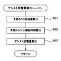
図6に示すアシスト放電量算出ルーチンでは、まず、301で、予測SOC超過量を算出する。この場合、図10(a)に示すように、走行予定経路における所定距離先までの予測SOCの挙動に基づいて、走行予定経路における所定距離先までの予測SOC超過量の挙動を算出する。
この後、302に進み、予測エンジン運転時間を算出する。この場合、図10(b)に示すように、走行予定経路における所定距離先までの予測エンジン動作状態の挙動に基づいて、走行予定経路における所定距離先までの予測エンジン運転時間の挙動を算出する。
この後、303に進み、アシスト放電量を算出する。この場合、図10(c)に示すように、走行予定経路における距離毎に、予測SOC超過量を予測エンジン運転時間で除算してアシスト放電量を求め、その最大値を最終的なアシスト放電量である指令アシスト放電量とする。このアシスト放電量を実現するようにエンジン11やMG12,13等を制御することで、高圧バッテリ20の放電量を増加させる放電増加制御を実行する。
以上説明した本実施例1では、車両の走行予定経路における道路勾配及び車速の予測結果に基づいて走行予定経路におけるSOCを予測する。その予測SOCに基づいて高圧バッテリ20が飽和状態になると判定した場合に、予測SOCに基づいて高圧バッテリ20が飽和状態にならないように予め高圧バッテリ20の放電量を増加させる放電増加制御を実行する。これにより、予測SOCが正しければ、予測SOCに基づいた放電増加制御により、SOCが上限値に到達しないように制御して、高圧バッテリ20が飽和状態になることを防止することができる。
更に、放電増加制御の開始後に、予測SOCの挙動が実際のSOCの挙動に対してずれているか又はSOCずれ要因が発生したか否かを判定する。その結果、予測SOCの挙動が実際のSOCの挙動に対してずれていると判定された場合又はSOCずれ要因が発生したと判定された場合に、走行予定経路におけるSOCの予測を再度実施して放電増加制御を修正する。これにより、予測SOCの挙動が実際のSOCの挙動に対してずれる場合でも、SOCの予測を再度実施することで予測SOCを修正することができる。更に、修正後の予測SOCに基づいて放電増加制御を修正して、修正後の放電増加制御により、SOCが上限値に到達しないように制御して、高圧バッテリ20が飽和状態になることを防止することができる。これにより、高圧バッテリ20が飽和状態になることを確実に防止して、回生発電を有効利用することができ、燃費を効果的に向上させることができる。
また、本実施例1では、放電増加制御を実行しない場合の現時点の予測SOCに対して予測SOCの予測時点から現時点までの放電増加制御による放電量増加分を差し引いたSOCを、放電増加制御を実行した場合の現地点の予測SOCとして求める。この放電増加制御を実行した場合の現地点の予測SOCと、現地点の実際のSOCとの差が所定値以上の場合に、予測SOCの挙動が実際のSOCの挙動に対してずれていると判定する。このようにすれば、放電増加制御を実行した場合の予測SOCと実際のSOCとを比較して、予測SOCの挙動が実際のSOCの挙動に対してずれていることを精度良く判定することができる。
また、本実施例1では、実際のSOCが所定値以下になった場合に、高圧バッテリ20の放電を禁止してエンジン11の動力で第1MG12又はMG12,13を回転駆動して第1MG12又はMG12,13で発電する。このようにすれば、SOCの過度の低下を抑制することができる。
この際、本実施例1では、第1MG12又はMG12,13の発電電力を電動コンプレッサ29を含む補機の消費電力の総和とする。このようにすれば、第1MG12又はMG12,13の発電電力を必要最小限に抑えながら、SOCの過度の低下を抑制することができる。
ところで、走行予定経路の予測が困難な場合には、SOCを正しく予測できないため、放電増加制御を実行すると、不確かな予測SOCに基づいた放電増加制御を実行することになり、燃費が悪化してしまう可能性がある。
そこで、本実施例1では、走行予定経路の予測が困難な場合に、放電増加制御を禁止する。これにより、不確かな予測SOCに基づいた放電増加制御による燃費の悪化を防止することができる。
更に、本実施例1では、高圧バッテリ20が劣化している(つまり高圧バッテリ20の劣化状態が所定以上)の場合に、放電増加制御を禁止する。これにより、高圧バッテリ20の劣化が激しく、充放電をあまり行わない方が良い場合には、放電増加制御を禁止して、高圧バッテリ20の破損を防止することができる。
また、本実施例1では、放電増加制御の際に、アシスト走行により高圧バッテリ20の放電を行うアシスト放電やEV走行により高圧バッテリ20の放電を行うにEV放電で高圧バッテリ20の放電量を増加させる。このようにすれば、アシスト放電やEV放電により高圧バッテリ20の電力を車両の駆動力に変換して有効利用しながら、高圧バッテリ20の放電量を増加させることができる。
尚、放電増加制御の際に、アシスト放電とEV放電の両方で高圧バッテリ20の放電量を増加させるようにしても良いが、アシスト放電とEV放電のうちの一方のみで高圧バッテリ20の放電量を増加させるようにしても良い。
上記実施例1では、アシスト放電のみで放電増加制御を行う場合のアシスト放電量の算出方法を説明したが、アシスト放電とEV放電の両方で放電増加制御を行う場合には、アシスト放電量を次のようにして算出するようにしても良い。
車両の走行出力が小さい場合に、アシスト放電による高圧バッテリ20の放電電力であるMGの出力を大きくすると、エンジン11の出力を小さくしてエンジン11の効率が低い領域である燃費が悪い領域でエンジン11を運転することになる。
そこで、図11に示すアシスト放電量のマップを参照して、車両の走行出力に応じたアシスト放電量を算出する。このアシスト放電量のマップは、車両の走行出力が大きいほどアシスト放電量が大きくなり、車両の走行出力が小さいほどアシスト放電量が小さくなるように設定されている。これにより、車両の走行出力が大きいほどアシスト放電電力であるアシスト放電による高圧バッテリ20の放電電力を大きくし、車両の走行出力が小さいほどアシスト放電電力を小さくする。
このようにすれば、車両の走行出力が小さい場合でも、アシスト放電電力を小さくすることで、エンジン11の出力をあまり小さくせずにエンジン11の効率が高い領域である燃費が良い領域でエンジン11を運転することができる。一方、車両の走行出力が大きい場合には、アシスト放電電力を大きくしても、エンジン11の出力を大きくしてエンジン11の効率が高い領域でエンジンを運転することができる。
次に、図12を用いて本開示の実施例2を説明する。但し、実施例1と実質的に同一又は類似部分には同一符号を付して説明を省略又は簡略化し、主として実施例1と異なる部分について説明する。
本実施例2では、図12に示すように、車両の動力源としてエンジン11と一つのMG12とが搭載されている。エンジン11の出力軸の動力が一つのMG12を介して変速機14に伝達される。このような構成のハイブリッド車に本開示を適用して実施しても良い。
尚、上記実施例2では、エンジン11から変速機14までの動力伝達経路にクラッチを設けないが、これに限定されず、例えば、エンジン11とMG12との間にクラッチを設けたり、MG12と変速機14との間にクラッチを設けても良い。或は、変速機14にクラッチを内蔵しても良い。また、変速機14を省略しても良い。
次に、図13を用いて本開示の実施例3を説明する。但し、実施例1と実質的に同一又は類似部分には同一符号を付して説明を省略又は簡略化し、主として実施例1と異なる部分について説明する。
本実施例3では、図13に示すように、車両の動力源としてエンジン11と二つのMG12,13とが搭載されている。エンジン11の出力軸と第1MG12の回転軸と第2MG13の回転軸とが動力分割機構である遊星ギヤ機構53を介して連結され、第2MG13の回転軸が駆動軸54に連結されている。第1MG12と第2MG13は、それぞれ第1インバータ19Aと第2インバータ19Bを介して高圧バッテリ20と電力を授受する。このような構成のハイブリッド車に本開示を適用して実施しても良い。
尚、本開示は、図1、図12、図13に示す構成のハイブリッド車に限定されず、車両の動力源としてエンジンとMGとを搭載した種々の構成のハイブリッド車に適用して実施できる。
また、予測SOCの挙動が実際のSOCの挙動に対してずれているか否かの判定方法は、上記実施例で説明した方法に限定されず、適宜変更しても良い。例えば、放電増加制御を実行しない場合の現時点の予測SOCと、予測SOCの予測時点から現時点までの放電増加制御による放電量増加分を現地点の実際のSOCに加算したSOCとの差が所定値以上の場合に、予測SOCの挙動が実際のSOCの挙動に対してずれていると判定するようにしても良い。
また、上記実施例では、SOCずれ要因として、走行経路の変更、補機の作動状態の変化、風速の変化、風向の変化、路面状態の変化が発生したか否かを判定する。しかし、これに限定されず、SOCずれ要因として、他の車両制御(予測されていない停車や急加速や急減速等)や環境変化(例えば温度や気圧の変化等)が発生したか否かを判定するようにしても良い。
また、実際のSOCが所定値以下になった場合に高圧バッテリの放電を禁止してエンジンの動力でMGを回転駆動して発電する機能と、走行予定経路の予測が困難な場合に放電増加制御を禁止する機能と、バッテリの劣化状態が所定以上の場合に放電増加制御を禁止する機能のうちの少なくとも一つを省略しても良い。
また、上記実施例では、放電増加制御の際に、アシスト放電やEV放電で高圧バッテリの放電量を増加させるようにしたが、他の方法で高圧バッテリの放電量を増加させるようにしても良い。
また、上記実施例では、ハイブリッドECU39で、図4乃至図6の各ルーチンを実行する。しかし、これに限定されず、ハイブリッドECU39以外の他のECU(例えばエンジンECU40やMG-ECU42等のうちの少なくとも一つ)で各ルーチンを実行するようにしても良い。或は、ハイブリッドECU39と他のECUの両方で各ルーチンを実行するようにしても良い。
また、上記実施例において、ECUが実行する機能の一部又は全部を、一つ或は複数のIC等によりハードウェア的に構成しても良い。
本開示は、実施例に準拠して記述されたが、本開示は当該実施例や構造に限定されるものではないと理解される。本開示は、様々な変形例や均等範囲内の変形をも包含する。加えて、様々な組み合わせや形態、さらには、それらに一要素のみ、それ以上、あるいはそれ以下、を含む他の組み合わせや形態をも、本開示の範疇や思想範囲に入るものである。
Claims (12)
- 車両の動力源となるエンジン(11)及びモータジェネレータ(12、13)と、前記モータジェネレータと電力を授受するバッテリ(20)とを備え、前記車両を制動する際に前記モータジェネレータで回生発電した電力である回生電力を前記バッテリに充電する車両の制御装置において、
前記車両の走行予定経路における道路勾配及び車速の予測結果に基づいて前記走行予定経路における前記バッテリの残容量を表すSOCを予測するSOC予測部(39、50、205)と、
前記SOC予測部で予測したSOCである予測SOCに基づいて前記バッテリが前記回生電力を充電できない飽和状態になると判定した場合に、前記予測SOCに基づいて前記バッテリが前記飽和状態にならないように予め前記バッテリの放電量を増加させる放電増加制御を実行する放電制御部(39、52、206、208、301~303)と、
前記放電増加制御の開始後に、前記予測SOCの挙動が実際のSOCの挙動に対してずれているか又は前記予測SOCの挙動が前記実際のSOCの挙動に対してずれると予想される車両制御又は環境変化であるSOCずれ要因が発生したか否かを判定する判定部(39、105~109)と、
前記判定部で前記予測SOCの挙動が実際のSOCの挙動に対してずれていると判定された場合又は前記SOCずれ要因が発生したと判定された場合に、前記走行予定経路におけるSOCの予測を再度実施して前記放電増加制御を修正する修正部(39、110、201~209、301~303)と
を備えている車両の制御装置。 - 前記判定部は、前記放電増加制御を実行しない場合の現時点の予測SOCに対して前記予測SOCの予測時点から現時点までの前記放電増加制御による放電量増加分を差し引いたSOCと、現地点の実際のSOCとの差が所定値以上の場合に、前記予測SOCの挙動が実際のSOCの挙動に対してずれていると判定する請求項1に記載の車両の制御装置。
- 前記判定部は、前記SOCずれ要因として、走行経路の変更、補機の作動状態の変化、風速の変化、風向の変化、路面状態の変化のうちの少なくとも一つが発生したか否かを判定する請求項1又は2に記載の車両の制御装置。
- 前記実際のSOCが所定値以下になった場合に、前記バッテリの放電を禁止して前記エンジンの動力で前記モータジェネレータを回転駆動して前記モータジェネレータで発電するSOC低下抑制部(39、104、114)を備えている請求項1乃至3のいずれかに記載の車両の制御装置。
- 前記SOC低下抑制部は、前記モータジェネレータの発電電力を空調用の電動コンプレッサ(29)を含む補機の消費電力の総和とする請求項4に記載の車両の制御装置。
- 前記走行予定経路の予測が困難な場合に、前記放電増加制御を禁止する第1禁止部(39、101、112)を備えている請求項1乃至5のいずれかに記載の車両の制御装置。
- 前記第1禁止部は、前記車両の目的地情報が得られず且つ進行方向の経路分岐数が所定値以上の場合に、前記走行予定経路の予測が困難と判定する請求項6に記載の車両の制御装置。
- 前記バッテリの劣化状態が所定以上の場合に、前記放電増加制御を禁止する第2禁止部(39、102、112)を備えている請求項1乃至7のいずれかに記載の車両の制御装置。
- 前記放電制御部は、前記放電増加制御の際に、前記エンジンの動力と前記モータジェネレータの動力の両方で前記車両を走行させるアシスト走行により前記バッテリの放電を行うアシスト放電と、前記モータジェネレータの動力のみで前記車両を走行させるEV走行により前記バッテリの放電を行うにEV放電のうちの少なくとも一方で、前記バッテリの放電量を増加させる請求項1乃至8のいずれかに記載の車両の制御装置。
- 前記放電制御部は、前記車両の走行出力が大きいほど前記アシスト放電による前記バッテリの放電電力を大きくし、前記車両の走行出力が小さいほど前記アシスト放電による前記バッテリの放電電力を小さくする請求項9に記載の車両の制御装置。
- 自車位置情報、走行予定経路等に基づいて、走行予定経路における所定距離先までの道路勾配の挙動を予測する道路勾配予測部(39、46、203)を備えている請求項1乃至10のいずれかに記載の車両の制御装置。
- 自車位置情報、走行予定経路、制限速度情報、交通情報、気象情報、周辺情報等に基づいて、走行予定経路における所定距離先までの車速の挙動を予測する車速予測部(39、47、204)を備えている請求項1乃至11のいずれかに記載の車両の制御装置。
Priority Applications (3)
| Application Number | Priority Date | Filing Date | Title |
|---|---|---|---|
| CN201680064401.0A CN108349486B (zh) | 2015-11-06 | 2016-10-06 | 车辆控制装置 |
| US15/765,158 US10946764B2 (en) | 2015-11-06 | 2016-10-06 | Controller for vehicle |
| DE112016005098.4T DE112016005098B4 (de) | 2015-11-06 | 2016-10-06 | Steuerungsvorrichtung für ein Fahrzeug |
Applications Claiming Priority (2)
| Application Number | Priority Date | Filing Date | Title |
|---|---|---|---|
| JP2015218983A JP6406215B2 (ja) | 2015-11-06 | 2015-11-06 | 車両の制御装置 |
| JP2015-218983 | 2015-11-06 |
Publications (1)
| Publication Number | Publication Date |
|---|---|
| WO2017077808A1 true WO2017077808A1 (ja) | 2017-05-11 |
Family
ID=58662393
Family Applications (1)
| Application Number | Title | Priority Date | Filing Date |
|---|---|---|---|
| PCT/JP2016/079720 Ceased WO2017077808A1 (ja) | 2015-11-06 | 2016-10-06 | 車両の制御装置 |
Country Status (5)
| Country | Link |
|---|---|
| US (1) | US10946764B2 (ja) |
| JP (1) | JP6406215B2 (ja) |
| CN (1) | CN108349486B (ja) |
| DE (1) | DE112016005098B4 (ja) |
| WO (1) | WO2017077808A1 (ja) |
Cited By (4)
| Publication number | Priority date | Publication date | Assignee | Title |
|---|---|---|---|---|
| JP2019001351A (ja) * | 2017-06-16 | 2019-01-10 | 本田技研工業株式会社 | ハイブリッド車両 |
| JP2020171121A (ja) * | 2019-04-03 | 2020-10-15 | 三菱重工業株式会社 | 計画装置及び計画方法 |
| CN113942514A (zh) * | 2020-07-16 | 2022-01-18 | 上海汽车集团股份有限公司 | 能耗优化方法,装置及存储介质 |
| CN115648344A (zh) * | 2022-12-28 | 2023-01-31 | 成都普什信息自动化有限公司 | 一种rfid标签结构的模切方法及系统 |
Families Citing this family (30)
| Publication number | Priority date | Publication date | Assignee | Title |
|---|---|---|---|---|
| DE102015223588B4 (de) * | 2015-11-27 | 2025-10-23 | Bayerische Motoren Werke Aktiengesellschaft | Steuersystem mit mindestens einer elektronischen Steuereinheit zur Steuerung eines Verbrennungsmotors in einem Hybridfahrzeug |
| US10286899B2 (en) * | 2016-11-16 | 2019-05-14 | Ford Global Technologies, Llc | Operation of power electronics during battery communication loss |
| KR102443338B1 (ko) * | 2017-09-12 | 2022-09-15 | 현대자동차주식회사 | 배터리 충전 제어방법 및 시스템 |
| JP7013826B2 (ja) * | 2017-12-05 | 2022-02-01 | トヨタ自動車株式会社 | ハイブリッド自動車およびこれに搭載される制御装置 |
| JP7006311B2 (ja) | 2018-01-29 | 2022-01-24 | トヨタ自動車株式会社 | 電動車両及び電動車両の制御方法 |
| KR20200054512A (ko) * | 2018-11-12 | 2020-05-20 | 현대자동차주식회사 | 친환경 차량의 제동 제어 시스템 및 방법 |
| JP7119941B2 (ja) * | 2018-11-22 | 2022-08-17 | トヨタ自動車株式会社 | 車両の制御システム |
| JP7501250B2 (ja) * | 2019-11-12 | 2024-06-18 | トヨタ自動車株式会社 | 走行制御装置、方法およびプログラム |
| JP7238750B2 (ja) * | 2019-12-11 | 2023-03-14 | トヨタ自動車株式会社 | 走行制御装置、方法、プログラムおよび車両 |
| CN111497821B (zh) * | 2020-04-08 | 2022-03-25 | 北京汽车股份有限公司 | 混动车辆的能量管理方法 |
| CN113968148B (zh) * | 2020-07-23 | 2025-04-22 | 厦门雅迅智联科技股份有限公司 | 一种增程式电动车的充电控制方法、系统和电动车 |
| JP7598235B2 (ja) * | 2020-12-07 | 2024-12-11 | 日産自動車株式会社 | 車両の制御方法及び車両の制御システム |
| CN112572404B (zh) * | 2020-12-24 | 2021-11-30 | 吉林大学 | 基于前方道路信息的重型商用车混合动力能量管理方法 |
| JP2022139826A (ja) * | 2021-03-12 | 2022-09-26 | 本田技研工業株式会社 | 車両の制御装置、車両の制御方法およびプログラム |
| CN112784824A (zh) * | 2021-03-18 | 2021-05-11 | 广州海格星航信息科技有限公司 | 一种智能驾驶深度学习模型管理方法、装置及系统 |
| US11708007B2 (en) * | 2021-08-02 | 2023-07-25 | Ford Global Technologies, Llc | Control systems and methods for modifying a battery state of charge signal |
| US12038769B2 (en) | 2021-11-29 | 2024-07-16 | Caterpillar Global Mining Equipment Llc | Battery management for machine service operations |
| US12077065B2 (en) | 2021-11-29 | 2024-09-03 | Caterpillar Global Mining Equipment Llc | Brake control system for battery-powered machine |
| US12263754B2 (en) * | 2021-11-29 | 2025-04-01 | Caterpillar Inc. | Battery management for electric material- dispensing machine |
| US12124266B2 (en) | 2021-11-29 | 2024-10-22 | Caterpillar Inc. | Battery support service vehicle |
| WO2023170739A1 (ja) * | 2022-03-07 | 2023-09-14 | 日立Astemo株式会社 | Soc予測システム |
| DE102022205065A1 (de) | 2022-05-20 | 2023-11-23 | Psa Automobiles Sa | Hybridantrieb für ein Kraftfahrzeug und Verfahren zum Betreiben desselben |
| US12236732B2 (en) | 2022-07-06 | 2025-02-25 | International Engine Intellectual Property Company, Llc | Intelligent charge limit for high voltage batteries |
| CN115257407B (zh) * | 2022-08-16 | 2024-07-30 | 中联重科股份有限公司 | 增程式电动车辆的能量管理方法、终端及计算机存储介质 |
| JP7722302B2 (ja) * | 2022-09-06 | 2025-08-13 | トヨタ自動車株式会社 | 自動車 |
| CN115754770B (zh) * | 2022-11-16 | 2026-02-24 | 东风商用车有限公司 | 电池soc修正方法、装置、设备及可读存储介质 |
| CN116101255B (zh) * | 2023-02-10 | 2024-03-08 | 广州汽车集团股份有限公司 | 发动机的启停控制方法及装置、设备、介质 |
| WO2024170076A1 (en) * | 2023-02-15 | 2024-08-22 | Abb Schweiz Ag | Method of determining a road surface condition, road, surface condition monitoring system, for monitoring an industrial site, and computer program product |
| US20240425030A1 (en) * | 2023-06-26 | 2024-12-26 | Fca Us Llc | Intelligent optimized energy storage control for electrified vehicles |
| CN119975098B (zh) * | 2025-03-21 | 2025-10-24 | 潍柴动力股份有限公司 | 一种增程矿卡的soc规划方法及相关装置 |
Citations (5)
| Publication number | Priority date | Publication date | Assignee | Title |
|---|---|---|---|---|
| JP2007050888A (ja) * | 2006-09-25 | 2007-03-01 | Aisin Aw Co Ltd | ハイブリッド車両の駆動制御システム |
| JP2009001099A (ja) * | 2007-06-20 | 2009-01-08 | Denso Corp | 充放電管理装置および充放電管理装置用のプログラム |
| JP2009274610A (ja) * | 2008-05-15 | 2009-11-26 | Honda Motor Co Ltd | ハイブリッド車の制御装置 |
| JP2010125868A (ja) * | 2008-11-25 | 2010-06-10 | Denso Corp | 充放電計画装置 |
| JP2012050299A (ja) * | 2010-08-30 | 2012-03-08 | Denso Corp | 車両用充放電管理システム |
Family Cites Families (9)
| Publication number | Priority date | Publication date | Assignee | Title |
|---|---|---|---|---|
| DE10035027A1 (de) | 2000-07-19 | 2002-01-31 | Daimler Chrysler Ag | Verfahren zur Steuerung des Betriebsmodus von Fahrzeugen mit Hybridantrieben |
| JP3904388B2 (ja) | 2000-12-04 | 2007-04-11 | 松下電器産業株式会社 | ハイブリッド自動車の制御装置 |
| JP4442646B2 (ja) * | 2007-06-20 | 2010-03-31 | 株式会社デンソー | 車両用発電制御装置及び制御システム |
| WO2009129106A1 (en) * | 2008-04-15 | 2009-10-22 | The Uwm Research Foundation, Inc. | Power management systems and methods in a hybrid vehicle |
| JP5747986B2 (ja) * | 2011-08-03 | 2015-07-15 | トヨタ自動車株式会社 | ハイブリッド車両およびその制御方法 |
| CN102765388B (zh) * | 2012-07-03 | 2014-09-10 | 清华大学 | 一种基于多信息融合的整车控制方法 |
| US10703219B2 (en) * | 2013-10-04 | 2020-07-07 | Ford Global Technologies, Llc | Vehicle battery charge setpoint control |
| JP2015218983A (ja) | 2014-05-20 | 2015-12-07 | 積水化学工業株式会社 | 採熱システムの施工方法 |
| CN104260724B (zh) * | 2014-09-22 | 2017-02-15 | 李治良 | 一种车辆智能预测控制系统及其方法 |
-
2015
- 2015-11-06 JP JP2015218983A patent/JP6406215B2/ja active Active
-
2016
- 2016-10-06 CN CN201680064401.0A patent/CN108349486B/zh active Active
- 2016-10-06 DE DE112016005098.4T patent/DE112016005098B4/de active Active
- 2016-10-06 WO PCT/JP2016/079720 patent/WO2017077808A1/ja not_active Ceased
- 2016-10-06 US US15/765,158 patent/US10946764B2/en active Active
Patent Citations (5)
| Publication number | Priority date | Publication date | Assignee | Title |
|---|---|---|---|---|
| JP2007050888A (ja) * | 2006-09-25 | 2007-03-01 | Aisin Aw Co Ltd | ハイブリッド車両の駆動制御システム |
| JP2009001099A (ja) * | 2007-06-20 | 2009-01-08 | Denso Corp | 充放電管理装置および充放電管理装置用のプログラム |
| JP2009274610A (ja) * | 2008-05-15 | 2009-11-26 | Honda Motor Co Ltd | ハイブリッド車の制御装置 |
| JP2010125868A (ja) * | 2008-11-25 | 2010-06-10 | Denso Corp | 充放電計画装置 |
| JP2012050299A (ja) * | 2010-08-30 | 2012-03-08 | Denso Corp | 車両用充放電管理システム |
Cited By (8)
| Publication number | Priority date | Publication date | Assignee | Title |
|---|---|---|---|---|
| JP2019001351A (ja) * | 2017-06-16 | 2019-01-10 | 本田技研工業株式会社 | ハイブリッド車両 |
| US11312358B2 (en) | 2017-06-16 | 2022-04-26 | Honda Motor Co., Ltd. | Hybrid vehicle |
| JP2020171121A (ja) * | 2019-04-03 | 2020-10-15 | 三菱重工業株式会社 | 計画装置及び計画方法 |
| JP7267814B2 (ja) | 2019-04-03 | 2023-05-02 | 三菱重工業株式会社 | 計画装置及び計画方法 |
| CN113942514A (zh) * | 2020-07-16 | 2022-01-18 | 上海汽车集团股份有限公司 | 能耗优化方法,装置及存储介质 |
| CN113942514B (zh) * | 2020-07-16 | 2023-04-14 | 上海汽车集团股份有限公司 | 能耗优化方法,装置及存储介质 |
| CN115648344A (zh) * | 2022-12-28 | 2023-01-31 | 成都普什信息自动化有限公司 | 一种rfid标签结构的模切方法及系统 |
| CN115648344B (zh) * | 2022-12-28 | 2023-03-21 | 成都普什信息自动化有限公司 | 一种rfid标签结构的模切方法及系统 |
Also Published As
| Publication number | Publication date |
|---|---|
| DE112016005098B4 (de) | 2024-06-06 |
| CN108349486A (zh) | 2018-07-31 |
| JP6406215B2 (ja) | 2018-10-17 |
| CN108349486B (zh) | 2021-11-30 |
| DE112016005098T5 (de) | 2018-08-02 |
| JP2017087915A (ja) | 2017-05-25 |
| US10946764B2 (en) | 2021-03-16 |
| US20180273021A1 (en) | 2018-09-27 |
Similar Documents
| Publication | Publication Date | Title |
|---|---|---|
| JP6406215B2 (ja) | 車両の制御装置 | |
| JP6436071B2 (ja) | 車両の制御装置 | |
| JP6507625B2 (ja) | ハイブリッド車の制御装置 | |
| JP6089887B2 (ja) | ハイブリッド車の制御装置 | |
| KR100906908B1 (ko) | 하이브리드 전기 차량의 배터리 충전량 제어 방법 | |
| US9403439B2 (en) | Power generation control device | |
| JP6264258B2 (ja) | 車両の制御装置 | |
| KR101836250B1 (ko) | 구동 모터를 구비한 차량의 dc 컨버터의 출력 전압을 제어하는 방법 및 장치 | |
| KR100878969B1 (ko) | 하이브리드 전기 차량의 아이들 충전시 발전 제어 방법 | |
| KR20140079156A (ko) | 하이브리드 차량의 모터의 토크 결정 방법 및 시스템 | |
| US20120139481A1 (en) | Battery charge control apparatus | |
| JP6435789B2 (ja) | ハイブリッド駆動車両の出力制御装置 | |
| CN115871518A (zh) | 用于电能存储装置的热管理的方法和系统 | |
| KR101927180B1 (ko) | 구동 모터를 구비한 차량의 보조 배터리를 충전하는 방법 및 장치 | |
| KR20190056152A (ko) | 마일드 하이브리드 차량의 전력 제어 방법 및 장치 | |
| JP2012240566A (ja) | ハイブリッド車両の電気走行制御装置 | |
| WO2017135307A1 (ja) | 車両の空調装置 | |
| JP6070531B2 (ja) | ハイブリッド車の制御装置 | |
| JP6032192B2 (ja) | ハイブリッド車の制御装置 | |
| JP2016120740A (ja) | ハイブリッド車両の制御装置 |
Legal Events
| Date | Code | Title | Description |
|---|---|---|---|
| 121 | Ep: the epo has been informed by wipo that ep was designated in this application |
Ref document number: 16861875 Country of ref document: EP Kind code of ref document: A1 |
|
| WWE | Wipo information: entry into national phase |
Ref document number: 15765158 Country of ref document: US |
|
| WWE | Wipo information: entry into national phase |
Ref document number: 112016005098 Country of ref document: DE |
|
| 122 | Ep: pct application non-entry in european phase |
Ref document number: 16861875 Country of ref document: EP Kind code of ref document: A1 |