WO2017069280A1 - 熱交換器およびその組立て方法 - Google Patents
熱交換器およびその組立て方法 Download PDFInfo
- Publication number
- WO2017069280A1 WO2017069280A1 PCT/JP2016/081377 JP2016081377W WO2017069280A1 WO 2017069280 A1 WO2017069280 A1 WO 2017069280A1 JP 2016081377 W JP2016081377 W JP 2016081377W WO 2017069280 A1 WO2017069280 A1 WO 2017069280A1
- Authority
- WO
- WIPO (PCT)
- Prior art keywords
- heat exchanger
- packing
- header plate
- tank body
- edge
- Prior art date
Links
Images


Classifications
-
- F—MECHANICAL ENGINEERING; LIGHTING; HEATING; WEAPONS; BLASTING
- F28—HEAT EXCHANGE IN GENERAL
- F28F—DETAILS OF HEAT-EXCHANGE AND HEAT-TRANSFER APPARATUS, OF GENERAL APPLICATION
- F28F9/00—Casings; Header boxes; Auxiliary supports for elements; Auxiliary members within casings
- F28F9/02—Header boxes; End plates
- F28F9/0219—Arrangements for sealing end plates into casing or header box; Header box sub-elements
- F28F9/0224—Header boxes formed by sealing end plates into covers
- F28F9/0226—Header boxes formed by sealing end plates into covers with resilient gaskets
-
- F—MECHANICAL ENGINEERING; LIGHTING; HEATING; WEAPONS; BLASTING
- F28—HEAT EXCHANGE IN GENERAL
- F28F—DETAILS OF HEAT-EXCHANGE AND HEAT-TRANSFER APPARATUS, OF GENERAL APPLICATION
- F28F1/00—Tubular elements; Assemblies of tubular elements
- F28F1/10—Tubular elements and assemblies thereof with means for increasing heat-transfer area, e.g. with fins, with projections, with recesses
- F28F1/12—Tubular elements and assemblies thereof with means for increasing heat-transfer area, e.g. with fins, with projections, with recesses the means being only outside the tubular element
- F28F1/14—Tubular elements and assemblies thereof with means for increasing heat-transfer area, e.g. with fins, with projections, with recesses the means being only outside the tubular element and extending longitudinally
- F28F1/16—Tubular elements and assemblies thereof with means for increasing heat-transfer area, e.g. with fins, with projections, with recesses the means being only outside the tubular element and extending longitudinally the means being integral with the element, e.g. formed by extrusion
-
- F—MECHANICAL ENGINEERING; LIGHTING; HEATING; WEAPONS; BLASTING
- F28—HEAT EXCHANGE IN GENERAL
- F28F—DETAILS OF HEAT-EXCHANGE AND HEAT-TRANSFER APPARATUS, OF GENERAL APPLICATION
- F28F21/00—Constructions of heat-exchange apparatus characterised by the selection of particular materials
- F28F21/06—Constructions of heat-exchange apparatus characterised by the selection of particular materials of plastics material
- F28F21/067—Details
-
- F—MECHANICAL ENGINEERING; LIGHTING; HEATING; WEAPONS; BLASTING
- F28—HEAT EXCHANGE IN GENERAL
- F28F—DETAILS OF HEAT-EXCHANGE AND HEAT-TRANSFER APPARATUS, OF GENERAL APPLICATION
- F28F9/00—Casings; Header boxes; Auxiliary supports for elements; Auxiliary members within casings
- F28F9/001—Casings in the form of plate-like arrangements; Frames enclosing a heat exchange core
- F28F9/002—Casings in the form of plate-like arrangements; Frames enclosing a heat exchange core with fastening means for other structures
-
- F—MECHANICAL ENGINEERING; LIGHTING; HEATING; WEAPONS; BLASTING
- F28—HEAT EXCHANGE IN GENERAL
- F28F—DETAILS OF HEAT-EXCHANGE AND HEAT-TRANSFER APPARATUS, OF GENERAL APPLICATION
- F28F9/00—Casings; Header boxes; Auxiliary supports for elements; Auxiliary members within casings
- F28F9/02—Header boxes; End plates
- F28F9/04—Arrangements for sealing elements into header boxes or end plates
- F28F9/06—Arrangements for sealing elements into header boxes or end plates by dismountable joints
- F28F9/12—Arrangements for sealing elements into header boxes or end plates by dismountable joints by flange-type connections
-
- F—MECHANICAL ENGINEERING; LIGHTING; HEATING; WEAPONS; BLASTING
- F28—HEAT EXCHANGE IN GENERAL
- F28F—DETAILS OF HEAT-EXCHANGE AND HEAT-TRANSFER APPARATUS, OF GENERAL APPLICATION
- F28F2275/00—Fastening; Joining
- F28F2275/12—Fastening; Joining by methods involving deformation of the elements
- F28F2275/122—Fastening; Joining by methods involving deformation of the elements by crimping, caulking or clinching
-
- F—MECHANICAL ENGINEERING; LIGHTING; HEATING; WEAPONS; BLASTING
- F28—HEAT EXCHANGE IN GENERAL
- F28F—DETAILS OF HEAT-EXCHANGE AND HEAT-TRANSFER APPARATUS, OF GENERAL APPLICATION
- F28F9/00—Casings; Header boxes; Auxiliary supports for elements; Auxiliary members within casings
- F28F9/02—Header boxes; End plates
- F28F9/04—Arrangements for sealing elements into header boxes or end plates
- F28F9/16—Arrangements for sealing elements into header boxes or end plates by permanent joints, e.g. by rolling
- F28F9/18—Arrangements for sealing elements into header boxes or end plates by permanent joints, e.g. by rolling by welding
Definitions
- the present invention relates to a heat exchanger composed of a resin tank body, a header plate, and a packing, and particularly relates to an assembly structure of a tank and a header plate that can be made compact by reducing the tank width. .
- the heat exchanger described in the following Patent Document 1 has a flange portion projecting on the outer periphery of a resin tank, the end surface of the flange portion extends over the entire length, and is fitted into the annular groove of the header plate via a packing. It is.
- FIG. 15 is a cross-sectional view showing a state where the resin tank is attached to the header plate.
- the heat exchanger described in Patent Document 2 is such that an annular groove of a header plate is made as small as possible, and an end portion of a resin tank is fitted therein via a packing.
- the cross section is formed in a corrugated shape, and a flat tube is disposed between the concave portions of the wave.
- JP 2006-189206 A Japanese Patent Laying-Open No. 2015-87055
- the heat exchanger described in Patent Document 1 has a defect that the flange portion of the tank is always subjected to a force in the direction of lifting by the packing, and the positioning of the tank body and the header plate becomes unstable.
- the heat exchanger described in the cited document 2 has a packing groove made as thin as possible and a lower end of a resin tank in contact therewith, so that the reliability such as the pressure resistance of the seal is suspected. was there. Therefore, the present invention has an object to solve these problems.
- a header plate (2) in which tube insertion holes (2) are arranged in parallel with each other in the longitudinal direction, and the end of the flat tube (3) is inserted into the tube insertion hole (2).
- a heat exchanger having a resin tank body (5) fixed to the header plate (1) via an annular packing (7)
- the header plate (1) includes a bottom surface (1c) having a sealing surface (1a) with which a packing (7) is in contact and an insertion hole drilling surface (1b) provided with a tube insertion hole (2), and the bottom portion (1c).
- a tube end relief (11) that is recessed to A packing accommodating portion (12) formed between an outer side surface (10a) of each tooth portion (10), an end surface (6a) of the flange portion (6), and an inner peripheral surface of the peripheral wall (8); Comprising The tip edge (10b) inside the tooth portion (10) is seated on the outer edge (4a) of the convex portion (4), Heat exchange in which a packing (7) is disposed between the packing housing part (12) and the sealing surface (1a), and the tank body (5) is fixed to the header plate (1) by the crimping claws (9). It is a vessel.
- Invention of Claim 2 is the heat exchanger of Claim 1, Comprising: The said convex part (4) is a heat exchanger which is a planar convex part covering the whole penetration hole drilling surface (1b).
- Invention of Claim 3 is a heat exchanger of Claim 1, Comprising: The said convex part (4) is a heat exchanger which is a linear protrusion extended in the parallel direction of a tube penetration hole (2).
- Invention of Claim 4 is a heat exchanger of Claim 1, Comprising: The said convex part (4) is a heat exchanger which is a protrusion extended linearly between tube insertion holes (2).
- Claim 11 is the assembly method of the heat exchanger in any one of Claim 6 or Claim 9, Comprising: The annular packing (7) is stretched in the circumferential direction and attached to the side surface (10a) of the tooth portion (10) of the tank body (5), In that state, together with the packing (7), the step of fitting the opening of the tank body (5) to the sealing surface (1a) of the header plate (1); Next, a method of assembling the heat exchanger includes the step of caulking and fixing the tank body (5) with caulking claws (9) of the peripheral wall (8) of the header plate (1).
- the heat exchanger according to claim 1 includes a large number of tooth portions 10 projecting apart along the inner periphery of the tank body 5, tube end relief portions 11 formed between the tooth portions 10, and each tooth.
- Portion 10, packing housing portion 12 formed between end surface 6 a of flange portion 6 of tank body 5 and peripheral wall 8 of header plate 1, and tip edge 10 b of tooth portion 10 is a header.
- the packing 7 is disposed between the packing housing portion 12 and the seal surface 1 a of the header plate 1 in contact with the edge 4 a of the convex portion 4 of the plate 1. And it has the structure where the side edge 3a by the side of the long axis of the flat tube 3 is inserted in the tube end relief part 11 formed by denting between the tooth parts 10 of the tank main body 5.
- the side edge 3 a of the flat tube 3 can be moved closer to the peripheral wall 8 side than the edge 4 a of the convex portion 4 of the header plate 1.
- the width of the tank body 5 can be reduced, and the heat exchanger can be downsized.
- gear part 10 was seated on the edge 4a by the side of the sealing surface 1a of the said convex part 4, the positioning with the tank main body 5 and the header plate 1 is ensured, and it becomes a structure with high pressure
- the annular packing 7 is positioned in contact with the side edge 3a in the long axis direction of the opening of the flat tube 3, so that the packing 7 is securely attached. It holds and becomes a structure with good sealing performance.
- a burring portion 13 is formed upright at the hole edge of the tube insertion hole 2 of the header plate 1, and the side edge on the major axis side of the burring portion 13 is formed.
- a burring portion 13 is raised and formed at the hole edge of the tube insertion hole 2 of the header plate 1, and the side edge on the long axis side of the burring portion 13 is formed.
- the invention according to claim 10 is, in any one of the above-described configurations, “J” having no cross-section in the cross-section of the inner surface side of the cross-section of the tube end relief portion 11 between the tooth portions 10 toward the packing side. Because of the shape of the letter, it is possible to reduce the strength reduction of the tank body due to the thickness reduction.
- the annular packing 7 is stretched in the circumferential direction and attached to the side surface 10a of the tooth portion 10 of the tank body 5, And the step of fitting the opening of the tank body 5 together with the packing 7 to the seal surface 1a of the header plate 1 in a state, so that the packing 7 can be quickly and accurately fitted into the packing housing portion 12. it can.
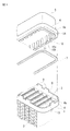
- FIG. 1 is an exploded perspective view of a main part of a heat exchanger according to a first embodiment of the present invention.
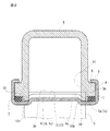
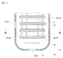
- FIG. 2 is a cross-sectional view of the main part.
- FIG. 3 is a perspective view of the main part.
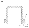
- FIG. 4 is a cross-sectional view of the tank body 5 used in the heat exchanger.
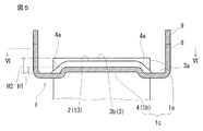
- FIG. 5 is a cross-sectional view of the header plate 1 used in the heat exchanger.
- 6 is a plan view of an essential part taken along the line VI-VI in FIG.
- FIG. 7 is a cross-sectional view of an essential part of a heat exchanger according to a second embodiment of the invention.
- FIG. 1 is an exploded perspective view of a main part of a heat exchanger according to a first embodiment of the present invention.
- FIG. 2 is a cross-sectional view of the main part.
- FIG. 3 is a perspective view of the main part.
- FIG. 4 is a cross-sectional view of the tank body 5 used
- the header plate 1 is formed by press molding of a metal plate (aluminum, aluminum alloy, stainless steel, etc.), and has a dish shape in which a side wall 8 is raised at the outer peripheral edge of the bottom portion 1c.
- the caulking claw 9 is protruded apart.
- the bottom surface 1 c of each header plate 1 is provided with an insertion hole drilling surface 1 b in which the tube insertion hole 2 is drilled, and a seal surface 1 a on which a packing is placed between the outer periphery and the side wall 8. In a state where the packing 7 is placed on the seal surface 1a, the tank body 5 is fitted therein.
- the tooth portion 10 protrudes from the end face 6 a of the flange portion 6 of the tank body 5, and a pair of arcuate tooth portions 14 (the left side is omitted) protrudes from both ends of the tank body 5 in the longitudinal direction. .
- the protrusion length from the end surface 6a of each tooth part 10 and a pair of arcuate tooth parts 14 is the same. That is, the end surface 6a of the tank body 5 and the outer side surface 10a of the tooth portion 10 form a step having an L-shaped cross section in the width direction of the tank body 5 as shown in FIGS.
- a tube end escape portion 11 is formed to be recessed so as to be aligned with the position of the tube insertion hole 2 of the flat tube 3. As shown in FIGS.
- the tube end relief portion 11 is recessed in a reverse “J” shape in which the transverse cross section of the tank body 5 in the width direction faces the end surface 6 a of the flange portion 6. is doing.
- tube insertion holes 2 are formed in the header plate 1 at regular intervals so as to be parallel to the longitudinal direction of the insertion hole formation surface 1b of the bottom surface 1c.
- a burring portion 13 is formed that rises in the direction in which the peripheral wall 8 of the header plate 1 rises.
- the convex part 4 is protrudingly provided in the position adjacent to each tube penetration hole 2 toward the starting direction of the surrounding wall 8. As shown in FIG. As shown in FIG. As shown in FIG.
- the leading edge 10 b of the tank body 5 is in contact with the outer edge 4 a of the convex portion 4.
- the convex portion 4 has a shape that swells in a planar shape from the inner bottom portion 1c of the header plate 1 over the entire insertion hole drilling surface 1b.
- the protruding height H1 of the header plate 1 from the inner bottom 1c is formed so as not to exceed the height H2 from the inner bottom 1c to the open end through which the flat tube 3 is inserted, as shown in FIG.
- an annular groove-shaped sealing surface 1 a is formed between the outer edge 4 a of the convex portion 4 and the peripheral wall 8 of the header plate 1.
- the tank body 5 is fitted on the header plate 1.
- the end surface 6 a of the flange portion 6 of the tank body 5 is placed on the seal surface 1 a through the packing 7.
- the inner edge portion 10 b of the tooth portion 10 and the arcuate tooth portion 14 of the tank body 5 abuts on the outer edge 4 a of the convex portion 4 of the header plate 1, and the tank body 5 is positioned. Is done.
- an annular packing housing portion 12 is formed by the groove-shaped sealing surface 1 a, the peripheral wall 8, the side surface 10 a of the tooth portion 10, and the end surface 6 a of the flange portion 6, and the packing 7 is disposed in the packing housing portion 12. It becomes a structure.
- the side edge 3a in the major axis direction of the opening 3b of the flat tube 3 protrudes toward the peripheral wall 8 side.
- the side edge 3 a is positioned closer to the peripheral wall 8 than the tip edge 10 b of the tooth portion 10 of the tank body 5.
- the width of the peripheral wall 8 is reduced, resulting in a compact structure.
- the packing 7 to 11 show a second embodiment of the present invention.
- the packing 7 is in contact with the tooth portion 10 of the tank body 5 as shown in FIG.
- the assembly method is characterized in that it can be easily assembled by attaching the packing 7 to the side surface 10a on the outer periphery of the tooth portion 10 of the tank body 5 in advance, as shown in FIG. Since the structure of the tank body 5 and the structure of the header plate 1 are the same as those in the first embodiment, the description thereof is omitted.
- the second embodiment as shown in FIG.
- the annular packing 7 is extended in advance to a step formed by the end surface 6 a of the flange portion 6 of the tank body 5 and the tooth portion 10 and the outer side surface 10 a of the arcuate tooth portion 14. In this state, attach to the inner circumference. At that time, the packing 7 slightly protrudes by the amount of the step 15 below the tip surfaces of the tooth portion 10 and the arcuate tooth portion 14. In that state, when the tank body 5 is fitted on the header plate 1 and pressed, the step 15 is pressed, and the inner periphery 7b of the packing 7 is pushed out as shown in FIGS. The packing 7 is positioned by abutting against the side edge on the long axis side of the burring portion 13 of the tube insertion hole 2 of each flat tube 3.
- the caulking claw 9 of the peripheral wall 8 is caulked to the flange portion 6 of the tank main body 5, and the tank main body 5 and the core are fixed.
- the example has been described in which the burring portion 13 is provided at the hole edge of the tube insertion hole 2, but the flat tube 3 is directly inserted into the header plate 1 without providing the burring portion 13. You can also.
- the packing 7 can be positioned by bringing the inner periphery of the packing 7 into contact with the side edge 3a of the end portion through which the flat tube 3 is inserted.
- the tube end relief portion 11 has a configuration in which the cross section is recessed in an inverted “J” shape having no head in the cross section, but is limited to this shape as long as the tube end can be inserted without difficulty. Is not to be done.
- the shape of the convex part 4 of the header plate 1 can be a ridge extending linearly between the tube insertion holes 2 as shown in FIGS.
- the shape of the convex part 4 of the header plate 1 can be a ridge extending linearly between the tube insertion holes 2 as shown in FIGS.
- FIG. 13 it can also be set as the linear protrusion extended in the parallel direction of the tube penetration hole 2.
- FIG. Further, as shown in FIG.
- the convex part 4 provided in the header plate 1 should just have the effect of the convex part 4 of the present invention (at least the function of preventing the positional deviation of the tooth part 10 of the tank main body 5), It is not limited.
Landscapes
- Engineering & Computer Science (AREA)
- Physics & Mathematics (AREA)
- Thermal Sciences (AREA)
- Mechanical Engineering (AREA)
- General Engineering & Computer Science (AREA)
- Geometry (AREA)
- Heat-Exchange Devices With Radiators And Conduit Assemblies (AREA)
- Gasket Seals (AREA)
- Details Of Heat-Exchange And Heat-Transfer (AREA)
Abstract
樹脂製のタンク本体(5)とヘッダプレート(1)とを位置決めしつつ、タンク本体(5)とヘッダプレート(1)との間にパッキン(7)を保持して、シール性を確保する。それとともに、偏平チューブ(3)の開口の長軸方向の幅をより広く取り、相対的にタンク本体(5)の幅を狭くして、コンパクトなタンク構造を提供する。 樹脂製のタンク本体(5)に定間隔に多数の歯部(10)を突出させ、その歯部(10)間にチューブ端逃がし部(11)を形成し、そこに偏平チューブ(3)の開口(3b)の長軸方向の側縁(3a)を位置させる。そして、歯部(10)とフランジ部(6)とヘッダプレート(1)のシール面(1a)と周壁(8)との間にパッキン収容部(12)を形成し、歯部(10)の先端縁(10b)を凸部(4)の縁(4a)に着座させる。そして、パッキン収容部(12)とシール面(1a)との間にパッキン(7)を配置する。
Description
本発明は、樹脂製のタンク本体とヘッダプレートおよびパッキンとからなる熱交換器であって、特に、タンク幅を縮小してコンパクトなものとすることができるタンクとヘッダプレートとの組付け構造に関する。
下記特許文献1に記載された熱交換器は、樹脂製タンクの外周にフランジ部を突設し、そのフランジ部の端面が全長に渡り、ヘッダプレートの環状溝にパッキンを介して嵌着したものである。図15は、その樹脂製のタンクをヘッダプレートに取付けた状態を示す横断面図である。
また、特許文献2に記載の熱交換器は、ヘッダプレートの環状溝を可及的に小さくし、そこにパッキンを介して樹脂製タンクの端部を嵌着したものである。そのタンクの内面側は、その横断面が波形に形成され、波の凹部間に偏平チューブを配置したものである。
また、特許文献2に記載の熱交換器は、ヘッダプレートの環状溝を可及的に小さくし、そこにパッキンを介して樹脂製タンクの端部を嵌着したものである。そのタンクの内面側は、その横断面が波形に形成され、波の凹部間に偏平チューブを配置したものである。
特許文献1に記載の熱交換器は、図15に示す如く、タンクのフランジ部は常にパッキンによって浮き上がる方向に力を受け、タンク本体とヘッダプレートとの位置決めが不安定になる欠点があった。
次に、引用文献2に記載の熱交換器は、パッキン溝を可及的に細くし、そこに樹脂製タンクの下端を当接したものであり、シールの耐圧等の信頼性が疑われる欠点があった。
そこで、本発明はこれらの問題点を解決することを課題とする。
次に、引用文献2に記載の熱交換器は、パッキン溝を可及的に細くし、そこに樹脂製タンクの下端を当接したものであり、シールの耐圧等の信頼性が疑われる欠点があった。
そこで、本発明はこれらの問題点を解決することを課題とする。
請求項1に記載の発明は、長手方向に互いに離間してチューブ挿通孔(2)が並設され、そのチューブ挿通孔(2)に偏平チューブ(3)の端部が挿通されるヘッダプレート(1)と、
前記ヘッダプレート(1)に、環状のパッキン(7)を介して固定される樹脂製のタンク本体(5)と、を有する熱交換器であって、
前記ヘッダプレート(1)は、パッキン(7)が接するシール面(1a)とチューブ挿通孔(2)が設けられる挿通孔穿設面(1b)とが備わる底部(1c)と、前記底部(1c)の外周縁に立ち上げられ、その縁部にカシメ爪(9)が形成された周壁(8)とからなり、
前記底部(1c)の挿通孔穿設面(1b)には、前記偏平チューブ(3)の開口(3b)を超えない範囲に、周壁(8)の立ち上げ方向に突出する凸部(4)が設けられており、
前記タンク本体(5)は、その開口にフランジ部(6)が設けられ、そのフランジ部(6)の内周に沿って離間し且つ、ヘッダプレート(1)のシール面(1a)に対向して、前記フランジ部(6)の端面(6a)から突出した多数の歯部(10)と、
前記歯部(10)の間に形成され、前記偏平チューブ(3)の開口の長軸方向の側縁(3a)が前記歯部(10)の内周より前記周壁(8)側に配置されるように凹陥したチューブ端逃がし部(11)と、
各歯部(10)の外側の側面(10a)と前記フランジ部(6)の端面(6a)と前記周壁(8)の内周面との間に形成されるパッキン収容部(12)と、を具備し、
前記歯部(10)の内側の先端縁(10b)が、前記凸部(4)の外周側の縁(4a)に着座し、
前記パッキン収容部(12)と前記シール面(1a)との間にパッキン(7)が配置され、前記カシメ爪(9)によってタンク本体(5)がヘッダプレート(1)に固定される熱交換器である。
請求項2に記載の発明は、請求項1に記載の熱交換器であって、
前記凸部(4)が、挿通孔穿設面(1b)の全体に亘る平面状の凸部である熱交換器である。
請求項3に記載の発明は、請求項1に記載の熱交換器であって、
前記凸部(4)が、チューブ挿通孔(2)の並列方向に延びる直線状の突条である熱交換器である。
請求項4に記載の発明は、請求項1に記載の熱交換器であって、
前記凸部(4)が、チューブ挿通孔(2)の間に直線状に延びる突条である熱交換器である。
請求項5に記載の発明は、請求項1~4のいずれかに記載の熱交換器であって、
前記歯部(10)の側面(10a)とパッキン(7)の間に隙間(101)が存在する熱交換器である。
請求項6に記載の発明は、請求項1~4のいずれかに記載の熱交換器であって、
前記パッキン(7)が前記歯部(10)の側面(10a)に接して位置決めされる熱交換器である。
請求項7に記載の発明は、請求項5に記載の熱交換器であって、
前記環状のパッキン(7)が、前記偏平チューブ(3)の開口の長軸方向の側縁(3a)に接して位置決めされる熱交換器である。
請求項8に記載の発明は、請求項5に記載の熱交換器であって、
前記ヘッダプレート(1)のチューブ挿通孔(2)の孔縁が、タンク本体(5)側に立ち上げられたバーリング加工部(13)に形成され、そのバーリング加工部(13)の長軸側の側縁で、前記環状のパッキン(7)が位置決めされる熱交換器である。
請求項9に記載の発明は、請求項6に記載の熱交換器であって、
前記ヘッダプレート(1)のチューブ挿通孔(2)の孔縁が、タンク本体(5)側に立ち上げられたバーリング加工部(13)に形成され、そのバーリング加工部(13)の長軸側の側縁で、前記環状のパッキン(7)が位置決めされる熱交換器である。
請求項10に記載の発明は、請求項1~請求項9のいずれかに記載の熱交換器であって、
前記歯部(10)間のチューブ端逃がし部(11)は、パッキン(7)側に向かって、横断面が頭部のない「J」の字状に次第にえぐれる形状とした熱交換器である。
上記請求項10の構成において、「J」の字状とは、図2のタンク本体5(上部のタンク本体)の右側壁のチューブ端逃がし部11の断面形状であり、左側壁ではその形状が右側壁の鏡写りに表れる。また、下部タンク本体5では「J」の字の向きが図2の形状と上下逆向きにあらわれる。また、「J」の字を別の表現にすれば半弓形である。即ち、弓の中心から上部半分の形状である。
請求項11に記載の発明は、請求項6又は請求項9のいずれかに記載の熱交換器の組立て方法であって、
前記環状のパッキン(7)を、周方向に引き伸ばして、タンク本体(5)の歯部(10)の側面(10a)に装着し、
その状態でそのパッキン(7)と共に、タンク本体(5)の開口部をヘッダプレート(1)のシール面(1a)に嵌着する工程と、
次いで、タンク本体(5)をヘッダプレート(1)の周壁(8)のカシメ爪(9)でカシメ固定する工程とを具備する熱交換器の組立て方法である。
請求項1に記載の熱交換器は、タンク本体5の内周に沿って離間して突出した多数の歯部10と、その歯部10間に形成されたチューブ端逃がし部11と、各歯部10と、タンク本体5のフランジ部6の端面6aと、ヘッダプレート1の周壁8との間に形成されるパッキン収容部12と、を具備し、前記歯部10の先端縁10bが、ヘッダプレート1の凸部4の縁4aに接触し、パッキン収容部12とヘッダプレート1のシール面1aとの間にパッキン7が配置されるものである。
そして、タンク本体5の歯部10間に凹陥して形成されるチューブ端逃がし部11に偏平チューブ3の長軸側の側縁3aが挿入される構造をもつ。
そのため、偏平チューブ3の側縁3aをヘッダプレート1の凸部4の縁4aよりも周壁8側に寄せることができる。その結果、タンク本体5の幅を小さくでき、熱交換器の小型化を実現できる。
しかも、前記歯部10の先端縁10bを、前記凸部4のシール面1a側の縁4aに着座したので、タンク本体5とヘッダプレート1との位置決めを確保し、耐圧性の高い構造となる。さらに、パッキン収容部12を歯部10の側面10aと、フランジ部6の端面6a、周壁8との間に確保し、タンクのシール性を良好とすることができる。
この凸部4の一例として、請求項2~請求項4のような形状を採用することができる。
特に、請求項3に記載の発明は、凸部4をチューブ挿通孔の並列方向に延びる直線状の突条としたので、平面に設けたリブの効果により、ヘッダの剛性を高めることができ、チューブとヘッダの接合部の強度を高めることもできる。
請求項5に記載の発明は、上記構成において、タンク本体5の歯部10の側面10aと環状のパッキン7との間に隙間101が設けられるため、歯部10がパッキン7に乗り上げることを防止することができ、シール性を良好にすることができる。
請求項6に記載の発明は、上記構成において、タンク本体5の歯部10の側面10aに前記環状のパッキン7が接してパッキン7の位置決めがされるため、パッキン7を正確にシール面1aに載置することができ、タンクのシール性を確保できる。
請求項7に記載の発明は、請求項5の構成において、前記環状のパッキン7が、前記偏平チューブ3の開口の長軸方向の側縁3aに接して位置決めされるため、パッキン7を確実に保持して、シール性のよい構造となる。
請求項8に記載の発明は、請求項5の構成において、ヘッダプレート1のチューブ挿通孔2の孔縁にバーリング加工部13が立ち上げ形成され、そのバーリング加工部13の長軸側の側縁で、前記環状のパッキン7が位置決めされるため、パッキン7が前記バーリング加工部13の側縁で位置決めされ、パッキン7を安定して保持できるとともに、バーリング加工部13により、偏平チューブ3の挿通端部が保護される。
請求項9に記載の発明は、請求項6の構成において、ヘッダプレート1のチューブ挿通孔2の孔縁にバーリング加工部13が立ち上げ形成され、そのバーリング加工部13の長軸側の側縁で、前記環状のパッキン7が位置決めされるため、パッキン7の位置決めを容易に行うことができるとともに、バーリング加工部13により、偏平チューブ3の挿通端部が保護される。
請求項10に記載の発明は、上記いずれかの構成において、歯部10間のチューブ端逃がし部11の横断面の内面側を、パッキン側に向かって、横断面が頭部のない「J」の字状にしたものであるため、肉厚減少によるタンク本体の強度低下を低減できる。
請求項11に記載の発明は、請求項6又は請求項9のいずれかの構成において、環状のパッキン7を、周方向に引き伸ばして、タンク本体5の歯部10の側面10aに装着し、その状態でそのパッキン7と共に、タンク本体5の開口部をヘッダプレート1のシール面1aに嵌着する工程とを具備するため、パッキン7を迅速且つ、正確にパッキン収容部12に嵌着することができる。
図1は本発明の第1実施例の熱交換器の要部分解斜視図。
図2は同要部横断面図。
図3は同要部斜視図。
図4は同熱交換器に用いるタンク本体5の横断面図。
図5は同熱交換器に用いるヘッダプレート1の横断面図。
図6は図5のVI−VI矢視要部平面図。
図7は発明の第2実施例の熱交換器の要部横断面図。
図8は図7の歯部10及び弧状歯部14の外周にパッキン7を装着した状態を示す斜視図。
図9は図7のIX−IX矢視図。
図10は図9のX−X矢視断面図。
図11は本発明の熱交換器に用いるヘッダプレート1の他の例1を示す要部平面図。
図12は図11のXII−XII矢視図。
図13は本発明の熱交換器に用いるヘッダプレート1の他の例2を示す要部平面図。
図14は本発明の熱交換器に用いるヘッダプレート1の他の例3を示す要部平面図。
図15は従来型熱交換器の要部横断面図。
次に、図面に基づいて本発明の熱交換器につき、説明する。
図1~図6は、本発明の第1実施例を示している。
この熱交換器は、図1に示す如く、多数の偏平チューブ3が並列され、その偏平チューブ3の両開口3bの端部が一対のヘッダプレート1(下部側のタンクを省略する)の長手方向に並列して穿設されたチューブ挿通孔2に挿通される。そして、各チューブ3間にコルゲートフィンを配置してコアが形成され、高温の炉内でコアの各部品が一体にろう付けされる。ろう材は、予め、各部品間に塗布され、又は部材に被覆される。
このヘッダプレート1は、金属板(アルミニウム、アルミニウム合金、ステンレス等)のプレス成型よりなり、その底部1cの外周縁に側壁8が立ち上げられる皿状のものであり、側壁8の先端縁には、カシメ爪9が離間して突設されている。その各ヘッダプレート1の底面1cは、チューブ挿通孔2が穿設される挿通孔穿設面1bと、その外周と側壁8との間にパッキンが載置されるシール面1aが設けられる。
そのシール面1aにパッキン7が載置された状態で、タンク本体5がそこに被嵌される。タンク本体5は樹脂の射出成型により形成されたフランジ部6を有し、周縁に突設されたカシメ爪9によりタンク本体5がコアに固定される。
ここで、本発明は、樹脂製のタンク本体5とヘッダプレート1との組み付けの構造に特徴がある。このタンク本体5は、一つの面を開放する略方形箱状に形成され、その開放端の外周にフランジ部6が環状に形成される。それとともに、図1~図4に示す如く、タンク本体5の内面側の内周面に沿って、多数の歯部10が、突設されている。
その歯部10は、タンク本体5のフランジ部6の端面6aから突出しており、タンク本体5の長手方向の両端には、一対の弧状歯部14(左側を省略する。)が突設される。各歯部10と一対の弧状歯部14の端面6aからの突出長さは、同一である。
即ち、タンク本体5の端面6aと歯部10の外側の側面10aは、図2、図3に示す如く、タンク本体5の幅方向の横断面がL字状の段差を形成する。
これらの各歯部10間には、偏平チューブ3のチューブ挿通孔2の位置に整合するように、チューブ端逃がし部11が凹陥して形成される。このチューブ端逃がし部11は、図1~図3に示す如く、フランジ部6の端面6aに向かって、タンク本体5の幅方向の横断面が頭部のない逆「J」の字状に凹陥している。
次に、ヘッダプレート1には、図5、図6に示す如く、その底面1cの挿通孔穿設面1bの長手方向に並列するように、チューブ挿通孔2が定間隔に穿設される。チューブ挿通孔2の孔縁部には、ヘッダプレート1の周壁8の立ち上げ方向に向かって立ち上げられたバーリング加工部13が形成される。そして、各チューブ挿通孔2に隣接する位置に、周壁8の立ち上げ方向に向けて凸部4が突設される。そして図2に示す如く、その凸部4の外側の縁4aにタンク本体5の先端縁10bが当接するようになっている。
図1~図6の例では、その凸部4は、挿通孔穿設面1bの全体に亘りヘッダプレート1の内面底部1cから平面状に盛り上がった形状になっている。ヘッダプレート1の内面底部1cからの突出高さH1は、図5に示す如く、内面底部1cから偏平チューブ3の挿通された開口端部までの高さH2を超えないように形成される。
この凸部4を設けることにより、タンク本体5の歯部10を位置決めし、タンク本体5の横ずれを防止することができる。また、バーリング加工部13を設けることにより、タンク本体5に外力が加わった時に、偏平チューブ3の挿通端部にその外力が直接伝わって、偏平チューブ3の端部が変形することを防止できる。
この例では、凸部4の外側の縁4aとヘッダプレート1の周壁8との間に環状の溝形のシール面1aが形成される。
このような熱交換器のコアに樹脂製のタンク本体5を組み付ける際、予め、ヘッダプレート1のシール面1aに環状のパッキン7を配置する。その時、パッキン7の内周は、バーリング加工部13の長軸側の側縁に当接し、パッキン7が位置決めされる。
次いで、タンク本体5をヘッダプレート1に被嵌する。タンク本体5のフランジ部6の端面6aがパッキン7を介してシール面1aに載置される。その際、図2に示す如く、タンク本体5の歯部10と弧状歯部14の内側の先端縁10bが、ヘッダプレート1の凸部4の外側の縁4aに当接し、タンク本体5が位置決めされる。
その時、溝状のシール面1aと周壁8、歯部10の側面10aと、フランジ部6の端面6aとにより、環状のパッキン収容部12が形成され、そのパッキン収容部12にパッキン7が配置される構造になる。
バーリング加工部13の長軸側の側縁は、タンク本体5の歯部10の外側の側面10aより突出するように形成されているため、タンク本体5の歯部の外側の側面10aとパッキン7の内周との間に隙間101が生じる。このことにより、歯部10がパッキン7に乗り上げることが防止でき、良好なシール性を保つことができる。
また、各偏平チューブ3は、図2及び図3から明らかなように、ヘッダプレート1のバーリング加工部13のチューブ挿通孔2に挿通され、その側縁3aが各歯部10間のチューブ端逃がし部11に挿入される。それにより、偏平チューブ3の開口3bの長軸方向の側縁3aは、周壁8側に突出される。そしてその側縁3aは、タンク本体5の歯部10の先端縁10bよりも、周壁8側に位置される。その結果、周壁8の幅が縮小され、コンパクトな構造となる。
次いで、この状態で、ヘッダプレート1の周壁8の端部のカシメ爪9を、タンク本体5のフランジ部6側にカシメることにより、タンク本体5をコアに固定し、熱交換器を完成する。この時、パッキン7はシール面1a側に押圧され、水密構造を形成する。
図面では、本願の特徴となる部分を強調して記載しているため、熱交換器のタンク内部に流体を流通させる流体出入口等の必要な部分は、省略して記載している。それらは、タンク本体5を樹脂成型する際、タンク本体5と同時に形成される。
図7~図11は、本発明の第2実施例を示している。
第1実施例との違いは、図7に示す如く、パッキン7がタンク本体5の歯部10に接している点である。また、その組み立ての際、予め、図8に示す如く、パッキン7をタンク本体5の歯部10の外周の側面10aに被着することで、容易に組立てることができる組立て方法に特徴がある。
タンク本体5の構造と、ヘッダプレート1の構造は、第1実施例と同様なので説明を省略する。
第2実施例では、図8に示す如く、タンク本体5のフランジ部6の端面6aと歯部10,弧状歯部14の外側の側面10aとからなる段差に、予め、環状のパッキン7を引き延ばした状態で、その内周に被着する。その時、パッキン7は、歯部10,弧状歯部14の先端面より下側に、段差15の分だけ僅かに突出する。
その状態で、タンク本体5をヘッダプレート1に被嵌し、押圧すると、その段差15の分が押圧されて、図9、図10に示すように、パッキン7の内周7bが押し出されて、各偏平チューブ3のチューブ挿通孔2のバーリング加工部13の長軸側の側縁に当接されて、パッキン7が位置決めされる。この状態で、タンク本体5のフランジ部6に周壁8のカシメ爪9がカシメられて、タンク本体5とコアが固定される。
上記2つの実施例では、チューブ挿通孔2の孔縁にバーリング加工部13を設けた例により説明してきたが、バーリング加工部13を設けずに、そのまま偏平チューブ3をヘッダプレート1に挿通することもできる。この場合、パッキン7の内周を、偏平チューブ3の挿通された端部の側縁3aに接触させ、パッキン7を位置決めすることもできる。
また、図面では、チューブ端逃がし部11の形状を横断面が頭部のない逆「J」の字状に凹陥する構成をとるが、チューブ端を無理なく挿通できる形状であれば、これに限定されるものではない。
(ヘッダプレート1の凸部4の形状の他の例)
さらに、ヘッダプレート1の凸部4の形状は、図11、図12に示す如く、チューブ挿通孔2の間に直線状に延びる突条とすることができる。また、図13に示す如く、チューブ挿通孔2の並列方向に延びる直線状の突条とすることもできる。さらに、図14に示す如く、ディンプル状の突起を設けて凸部4とすることで、タンク本体5の歯部10の位置ずれ防止を行うこともできる。
ヘッダプレート1に設ける凸部4の形状は、本発明の凸部4の効果(少なくとも、タンク本体5の歯部10の位置ずれ防止機能)を奏するものであればよいので、上記の実施例に限定されない。
1 ヘッダプレート
1a シール面
1b 挿通孔穿設面
1c 底部
2 チューブ挿通孔
3 偏平チューブ
3a 側縁
3b 開口
4 凸部
4a 縁
5 タンク本体
6 フランジ部
6a 端面
7 パッキン
7b 内周
8 周壁
9 カシメ爪
10 歯部
10a 側面
10b 先端縁
11 チューブ端逃がし部
12 パッキン収容部
13 バーリング加工部
14 弧状歯部
15 段差
101 隙間
1a シール面
1b 挿通孔穿設面
1c 底部
2 チューブ挿通孔
3 偏平チューブ
3a 側縁
3b 開口
4 凸部
4a 縁
5 タンク本体
6 フランジ部
6a 端面
7 パッキン
7b 内周
8 周壁
9 カシメ爪
10 歯部
10a 側面
10b 先端縁
11 チューブ端逃がし部
12 パッキン収容部
13 バーリング加工部
14 弧状歯部
15 段差
101 隙間
Claims (11)
- 長手方向に互いに離間してチューブ挿通孔(2)が並設され、そのチューブ挿通孔(2)に偏平チューブ(3)の端部が挿通されるヘッダプレート(1)と、
前記ヘッダプレート(1)に、環状のパッキン(7)を介して固定される樹脂製のタンク本体(5)と、を有する熱交換器であって、
前記ヘッダプレート(1)は、パッキン(7)が接するシール面(1a)とチューブ挿通孔(2)が設けられる挿通孔穿設面(1b)とが備わる底部(1c)と、前記底部(1c)の外周縁に立ち上げられ、その縁部にカシメ爪(9)が形成された周壁(8)とからなり、
前記底部(1c)の挿通孔穿設面(1b)には、前記偏平チューブ(3)の開口(3b)を超えない範囲に、周壁(8)の立ち上げ方向に突出する凸部(4)が設けられており、
前記タンク本体(5)は、その開口にフランジ部(6)が設けられ、そのフランジ部(6)の内周に沿って離間し且つ、ヘッダプレート(1)のシール面(1a)に対向して、前記フランジ部(6)の端面(6a)から突出した多数の歯部(10)と、
前記歯部(10)の間に形成され、前記偏平チューブ(3)の開口の長軸方向の側縁(3a)が前記歯部(10)の内周より前記周壁(8)側に配置されるように凹陥したチューブ端逃がし部(11)と、
各歯部(10)の外側の側面(10a)と前記フランジ部(6)の端面(6a)と前記周壁(8)の内周面との間に形成されるパッキン収容部(12)と、を具備し、
前記歯部(10)の内側の先端縁(10b)が、前記凸部(4)の外周側の縁(4a)に着座し、
前記パッキン収容部(12)と前記シール面(1a)との間にパッキン(7)が配置され、前記カシメ爪(9)によってタンク本体(5)がヘッダプレート(1)に固定される熱交換器。 - 請求項1に記載の熱交換器であって、
前記凸部(4)が、挿通孔穿設面(1b)の全体に亘る平面状の凸部である熱交換器。 - 請求項1に記載の熱交換器であって、
前記凸部(4)が、チューブ挿通孔(2)の並列方向に延びる直線状の突条である熱交換器。 - 請求項1に記載の熱交換器であって、
前記凸部(4)が、チューブ挿通孔(2)の間に直線状に延びる突条である熱交換器。 - 請求項1~4のいずれかに記載の熱交換器であって、
前記歯部(10)の側面(10a)と前記環状のパッキン(7)の間に隙間(101)が存在する熱交換器。 - 請求項1~4のいずれかに記載の熱交換器であって、
前記環状のパッキン(7)が前記歯部(10)の側面(10a)に接して位置決めされる熱交換器。 - 請求項5に記載の熱交換器であって、
前記環状のパッキン(7)が、前記偏平チューブ(3)の開口の長軸方向の側縁(3a)に接して位置決めされる熱交換器。 - 請求項5に記載の熱交換器であって、
前記ヘッダプレート(1)のチューブ挿通孔(2)の孔縁が、周壁(8)の立ち上げ方向側に向けて立ち上げられたバーリング加工部(13)に形成され、そのバーリング加工部(13)の長軸側の側縁で、前記環状のパッキン(7)が位置決めされる熱交換器。 - 請求項6に記載の熱交換器であって、
前記ヘッダプレート(1)のチューブ挿通孔(2)の孔縁が、周壁(8)の立ち上げ方向側に向けて立ち上げられたバーリング加工部(13)に形成され、そのバーリング加工部(13)の長軸側の側縁で、前記環状のパッキン(7)が位置決めされる熱交換器。 - 請求項1~請求項9のいずれかに記載の熱交換器であって、
前記歯部(10)間のチューブ端逃がし部(11)は、パッキン(7)側に向かって、横断面が頭部のない「J」の字状に次第にえぐれる形状とした熱交換器。 - 請求項6又は請求項9のいずれかに記載の熱交換器の組立て方法であって、
前記環状のパッキン(7)を、周方向に引き伸ばして、タンク本体(5)の歯部(10)の側面(10a)に装着し、
その状態でそのパッキン(7)と共に、タンク本体(5)の開口部をヘッダプレート(1)のシール面(1a)に嵌着する工程と、
次いで、タンク本体(5)をヘッダプレート(1)の周壁(8)のカシメ爪(9)でカシメ固定する工程とを具備する熱交換器の組立て方法。
Priority Applications (4)
| Application Number | Priority Date | Filing Date | Title |
|---|---|---|---|
| EP16857593.4A EP3367039B1 (en) | 2015-10-22 | 2016-10-17 | Heat exchanger |
| JP2017545833A JP6796074B2 (ja) | 2015-10-22 | 2016-10-17 | 熱交換器およびその組立て方法 |
| CN201680060981.6A CN108139184B (zh) | 2015-10-22 | 2016-10-17 | 热交换器及其组装方法 |
| US15/768,997 US10724807B2 (en) | 2015-10-22 | 2016-10-17 | Heat exchanger and method for assembling same |
Applications Claiming Priority (2)
| Application Number | Priority Date | Filing Date | Title |
|---|---|---|---|
| JP2015208149 | 2015-10-22 | ||
| JP2015-208149 | 2015-10-22 |
Publications (1)
| Publication Number | Publication Date |
|---|---|
| WO2017069280A1 true WO2017069280A1 (ja) | 2017-04-27 |
Family
ID=58557587
Family Applications (1)
| Application Number | Title | Priority Date | Filing Date |
|---|---|---|---|
| PCT/JP2016/081377 WO2017069280A1 (ja) | 2015-10-22 | 2016-10-17 | 熱交換器およびその組立て方法 |
Country Status (5)
| Country | Link |
|---|---|
| US (1) | US10724807B2 (ja) |
| EP (1) | EP3367039B1 (ja) |
| JP (1) | JP6796074B2 (ja) |
| CN (1) | CN108139184B (ja) |
| WO (1) | WO2017069280A1 (ja) |
Cited By (5)
| Publication number | Priority date | Publication date | Assignee | Title |
|---|---|---|---|---|
| WO2020129155A1 (ja) * | 2018-12-18 | 2020-06-25 | 三菱電機株式会社 | 熱交換器および冷凍サイクル装置 |
| WO2020158364A1 (ja) * | 2019-02-01 | 2020-08-06 | 株式会社デンソー | 熱交換器 |
| WO2020250041A1 (ja) * | 2019-06-10 | 2020-12-17 | 株式会社ティラド | 熱交換器 |
| WO2021049505A1 (ja) * | 2019-09-13 | 2021-03-18 | 株式会社ティラド | 熱交換器のタンク構造 |
| CN114467002A (zh) * | 2019-10-18 | 2022-05-10 | 法雷奥自动系统公司 | 集管-箱组件 |
Families Citing this family (6)
| Publication number | Priority date | Publication date | Assignee | Title |
|---|---|---|---|---|
| CN110186310A (zh) * | 2019-05-09 | 2019-08-30 | 浙江银轮机械股份有限公司 | 热交换器的主板、集管组件及其制造方法、热交换器 |
| CN110940208A (zh) * | 2019-12-10 | 2020-03-31 | 江西莱利电气有限公司 | 冷却器 |
| US10697715B1 (en) * | 2019-12-10 | 2020-06-30 | Heat Tech Llc | Main header for internal combustion engine radiator |
| CN112483257A (zh) * | 2020-10-27 | 2021-03-12 | 中国船舶重工集团公司第七0三研究所 | 一种高密封性的燃气轮机间冷器 |
| CN113500367B (zh) * | 2021-07-30 | 2022-05-24 | 福建意格机械设备有限公司 | 用于装配散热器的自动布管机 |
| FR3127562B1 (fr) * | 2021-09-24 | 2024-01-19 | Sogefi Air & Cooling | Dispositif de distribution de liquide caloporteur |
Citations (4)
| Publication number | Priority date | Publication date | Assignee | Title |
|---|---|---|---|---|
| JPS62204185U (ja) * | 1986-06-10 | 1987-12-26 | ||
| JP2002195781A (ja) * | 2000-12-27 | 2002-07-10 | Calsonic Kansei Corp | 熱交換器のシール構造 |
| DE102010033850A1 (de) * | 2010-08-09 | 2012-02-09 | Volkswagen Aktiengesellschaft | Sammelkasten für einen Wärmetauscher |
| JP2015127631A (ja) * | 2013-11-27 | 2015-07-09 | 株式会社デンソー | 熱交換器 |
Family Cites Families (13)
| Publication number | Priority date | Publication date | Assignee | Title |
|---|---|---|---|---|
| US4997035A (en) * | 1990-04-02 | 1991-03-05 | Blackstone Corporation | Joint crevice corrosion inhibitor |
| JP3675348B2 (ja) * | 2001-03-23 | 2005-07-27 | 株式会社デンソー | 熱交換器 |
| WO2005066568A1 (en) * | 2003-12-19 | 2005-07-21 | Valeo, Inc. | Collar rib for heat exchanger tanks |
| FR2867553B1 (fr) * | 2004-03-10 | 2009-08-28 | Valeo Thermique Moteur Sa | Boite collectrice d'echangeur de chaleur avec joint d'etancheite |
| DE102004033784A1 (de) | 2004-07-12 | 2006-02-02 | Behr Gmbh & Co. Kg | Wärmetauscher, insbesondere Ladeluftkühler |
| JP2006189206A (ja) | 2005-01-06 | 2006-07-20 | Denso Corp | 熱交換器 |
| JP5264181B2 (ja) * | 2005-02-03 | 2013-08-14 | ベール ゲーエムベーハー ウント コー カーゲー | 熱交換器 |
| US7775226B2 (en) * | 2007-01-14 | 2010-08-17 | Crayella, Inc. | Umbrella |
| FR2967764B1 (fr) * | 2010-11-19 | 2012-12-21 | Valeo Systemes Thermiques | Boite collectrice et echangeur de chaleur correspondant |
| FR2968389B1 (fr) * | 2010-12-07 | 2015-03-06 | Valeo Systemes Thermiques | Boite collectrice pour echangeur de chaleur et echangeur de chaleur correspondant |
| JP6337442B2 (ja) | 2013-10-30 | 2018-06-06 | 株式会社デンソー | 熱交換器 |
| EP2871437B1 (en) * | 2013-11-08 | 2016-04-27 | MAHLE International GmbH | Heat exchanger |
| CN104791487A (zh) * | 2015-03-31 | 2015-07-22 | 北京华清燃气轮机与煤气化联合循环工程技术有限公司 | 一种增强高温压力容器气密性的方法 |
-
2016
- 2016-10-17 WO PCT/JP2016/081377 patent/WO2017069280A1/ja active Application Filing
- 2016-10-17 EP EP16857593.4A patent/EP3367039B1/en active Active
- 2016-10-17 CN CN201680060981.6A patent/CN108139184B/zh active Active
- 2016-10-17 US US15/768,997 patent/US10724807B2/en active Active
- 2016-10-17 JP JP2017545833A patent/JP6796074B2/ja active Active
Patent Citations (4)
| Publication number | Priority date | Publication date | Assignee | Title |
|---|---|---|---|---|
| JPS62204185U (ja) * | 1986-06-10 | 1987-12-26 | ||
| JP2002195781A (ja) * | 2000-12-27 | 2002-07-10 | Calsonic Kansei Corp | 熱交換器のシール構造 |
| DE102010033850A1 (de) * | 2010-08-09 | 2012-02-09 | Volkswagen Aktiengesellschaft | Sammelkasten für einen Wärmetauscher |
| JP2015127631A (ja) * | 2013-11-27 | 2015-07-09 | 株式会社デンソー | 熱交換器 |
Cited By (6)
| Publication number | Priority date | Publication date | Assignee | Title |
|---|---|---|---|---|
| WO2020129155A1 (ja) * | 2018-12-18 | 2020-06-25 | 三菱電機株式会社 | 熱交換器および冷凍サイクル装置 |
| WO2020158364A1 (ja) * | 2019-02-01 | 2020-08-06 | 株式会社デンソー | 熱交換器 |
| WO2020250041A1 (ja) * | 2019-06-10 | 2020-12-17 | 株式会社ティラド | 熱交換器 |
| WO2021049505A1 (ja) * | 2019-09-13 | 2021-03-18 | 株式会社ティラド | 熱交換器のタンク構造 |
| CN114341580A (zh) * | 2019-09-13 | 2022-04-12 | 株式会社T.Rad | 热交换器的箱结构 |
| CN114467002A (zh) * | 2019-10-18 | 2022-05-10 | 法雷奥自动系统公司 | 集管-箱组件 |
Also Published As
| Publication number | Publication date |
|---|---|
| JPWO2017069280A1 (ja) | 2018-08-09 |
| EP3367039A1 (en) | 2018-08-29 |
| CN108139184B (zh) | 2021-08-17 |
| JP6796074B2 (ja) | 2020-12-02 |
| EP3367039A4 (en) | 2019-06-19 |
| CN108139184A (zh) | 2018-06-08 |
| US20180306527A1 (en) | 2018-10-25 |
| EP3367039B1 (en) | 2021-04-14 |
| US10724807B2 (en) | 2020-07-28 |
Similar Documents
| Publication | Publication Date | Title |
|---|---|---|
| WO2017069280A1 (ja) | 熱交換器およびその組立て方法 | |
| US10634431B2 (en) | Structure of heat exchanger core without header plate | |
| JP6394202B2 (ja) | 熱交換器 | |
| EP3045850B1 (en) | Tank structure for header-plate-less heat exchanger | |
| WO2015133592A1 (ja) | タンクのシール構造 | |
| US10401095B2 (en) | Heat exchanger | |
| US20150233654A1 (en) | Tank for heat exchanger | |
| JP2009204217A (ja) | 熱交換器のチューブ接続構造 | |
| JP4760693B2 (ja) | 熱交換器 | |
| JP5060872B2 (ja) | ラジエータの樹脂タンク構造 | |
| WO2015159529A1 (ja) | 熱交換器 | |
| JPH07121451B2 (ja) | 熱交換器 | |
| KR101569668B1 (ko) | 라디에이터 | |
| KR101462884B1 (ko) | 열교환기의 헤더탱크 결합구조 | |
| JP4360977B2 (ja) | 熱交換器 | |
| JPH10160383A (ja) | 樹脂製熱交換器用タンクのカシメ構造 | |
| JP2001012891A (ja) | 熱交換器用タンクの製造方法およびそのタンク | |
| JP4794275B2 (ja) | 熱交換器 | |
| JP5612878B2 (ja) | 熱交換器 | |
| JP2017116202A (ja) | 熱交換器 | |
| KR101964185B1 (ko) | 열교환기용 가스켓 | |
| JP2021188803A (ja) | 熱交換器のタンク構造 | |
| JP2019168200A (ja) | 熱交換器のタンク構造 |
Legal Events
| Date | Code | Title | Description |
|---|---|---|---|
| 121 | Ep: the epo has been informed by wipo that ep was designated in this application |
Ref document number: 16857593 Country of ref document: EP Kind code of ref document: A1 |
|
| ENP | Entry into the national phase |
Ref document number: 2017545833 Country of ref document: JP Kind code of ref document: A |
|
| WWE | Wipo information: entry into national phase |
Ref document number: 15768997 Country of ref document: US |
|
| NENP | Non-entry into the national phase |
Ref country code: DE |