JP6337442B2 - 熱交換器 - Google Patents
熱交換器 Download PDFInfo
- Publication number
- JP6337442B2 JP6337442B2 JP2013225901A JP2013225901A JP6337442B2 JP 6337442 B2 JP6337442 B2 JP 6337442B2 JP 2013225901 A JP2013225901 A JP 2013225901A JP 2013225901 A JP2013225901 A JP 2013225901A JP 6337442 B2 JP6337442 B2 JP 6337442B2
- Authority
- JP
- Japan
- Prior art keywords
- tubes
- tank member
- edge
- claw
- tube
- Prior art date
- Legal status (The legal status is an assumption and is not a legal conclusion. Google has not performed a legal analysis and makes no representation as to the accuracy of the status listed.)
- Active
Links
Images


Classifications
-
- F—MECHANICAL ENGINEERING; LIGHTING; HEATING; WEAPONS; BLASTING
- F28—HEAT EXCHANGE IN GENERAL
- F28F—DETAILS OF HEAT-EXCHANGE AND HEAT-TRANSFER APPARATUS, OF GENERAL APPLICATION
- F28F9/00—Casings; Header boxes; Auxiliary supports for elements; Auxiliary members within casings
- F28F9/02—Header boxes; End plates
- F28F9/0219—Arrangements for sealing end plates into casing or header box; Header box sub-elements
- F28F9/0224—Header boxes formed by sealing end plates into covers
- F28F9/0226—Header boxes formed by sealing end plates into covers with resilient gaskets
-
- F—MECHANICAL ENGINEERING; LIGHTING; HEATING; WEAPONS; BLASTING
- F28—HEAT EXCHANGE IN GENERAL
- F28D—HEAT-EXCHANGE APPARATUS, NOT PROVIDED FOR IN ANOTHER SUBCLASS, IN WHICH THE HEAT-EXCHANGE MEDIA DO NOT COME INTO DIRECT CONTACT
- F28D1/00—Heat-exchange apparatus having stationary conduit assemblies for one heat-exchange medium only, the media being in contact with different sides of the conduit wall, in which the other heat-exchange medium is a large body of fluid, e.g. domestic or motor car radiators
- F28D1/02—Heat-exchange apparatus having stationary conduit assemblies for one heat-exchange medium only, the media being in contact with different sides of the conduit wall, in which the other heat-exchange medium is a large body of fluid, e.g. domestic or motor car radiators with heat-exchange conduits immersed in the body of fluid
- F28D1/04—Heat-exchange apparatus having stationary conduit assemblies for one heat-exchange medium only, the media being in contact with different sides of the conduit wall, in which the other heat-exchange medium is a large body of fluid, e.g. domestic or motor car radiators with heat-exchange conduits immersed in the body of fluid with tubular conduits
- F28D1/053—Heat-exchange apparatus having stationary conduit assemblies for one heat-exchange medium only, the media being in contact with different sides of the conduit wall, in which the other heat-exchange medium is a large body of fluid, e.g. domestic or motor car radiators with heat-exchange conduits immersed in the body of fluid with tubular conduits the conduits being straight
- F28D1/0535—Heat-exchange apparatus having stationary conduit assemblies for one heat-exchange medium only, the media being in contact with different sides of the conduit wall, in which the other heat-exchange medium is a large body of fluid, e.g. domestic or motor car radiators with heat-exchange conduits immersed in the body of fluid with tubular conduits the conduits being straight the conduits having a non-circular cross-section
- F28D1/05366—Assemblies of conduits connected to common headers, e.g. core type radiators
-
- F—MECHANICAL ENGINEERING; LIGHTING; HEATING; WEAPONS; BLASTING
- F28—HEAT EXCHANGE IN GENERAL
- F28F—DETAILS OF HEAT-EXCHANGE AND HEAT-TRANSFER APPARATUS, OF GENERAL APPLICATION
- F28F1/00—Tubular elements; Assemblies of tubular elements
- F28F1/10—Tubular elements and assemblies thereof with means for increasing heat-transfer area, e.g. with fins, with projections, with recesses
- F28F1/12—Tubular elements and assemblies thereof with means for increasing heat-transfer area, e.g. with fins, with projections, with recesses the means being only outside the tubular element
- F28F1/14—Tubular elements and assemblies thereof with means for increasing heat-transfer area, e.g. with fins, with projections, with recesses the means being only outside the tubular element and extending longitudinally
- F28F1/22—Tubular elements and assemblies thereof with means for increasing heat-transfer area, e.g. with fins, with projections, with recesses the means being only outside the tubular element and extending longitudinally the means having portions engaging further tubular elements
-
- F—MECHANICAL ENGINEERING; LIGHTING; HEATING; WEAPONS; BLASTING
- F28—HEAT EXCHANGE IN GENERAL
- F28F—DETAILS OF HEAT-EXCHANGE AND HEAT-TRANSFER APPARATUS, OF GENERAL APPLICATION
- F28F21/00—Constructions of heat-exchange apparatus characterised by the selection of particular materials
- F28F21/06—Constructions of heat-exchange apparatus characterised by the selection of particular materials of plastics material
- F28F21/062—Constructions of heat-exchange apparatus characterised by the selection of particular materials of plastics material the heat-exchange apparatus employing tubular conduits
-
- F—MECHANICAL ENGINEERING; LIGHTING; HEATING; WEAPONS; BLASTING
- F28—HEAT EXCHANGE IN GENERAL
- F28F—DETAILS OF HEAT-EXCHANGE AND HEAT-TRANSFER APPARATUS, OF GENERAL APPLICATION
- F28F2225/00—Reinforcing means
- F28F2225/08—Reinforcing means for header boxes
-
- F—MECHANICAL ENGINEERING; LIGHTING; HEATING; WEAPONS; BLASTING
- F28—HEAT EXCHANGE IN GENERAL
- F28F—DETAILS OF HEAT-EXCHANGE AND HEAT-TRANSFER APPARATUS, OF GENERAL APPLICATION
- F28F2275/00—Fastening; Joining
- F28F2275/12—Fastening; Joining by methods involving deformation of the elements
-
- F—MECHANICAL ENGINEERING; LIGHTING; HEATING; WEAPONS; BLASTING
- F28—HEAT EXCHANGE IN GENERAL
- F28F—DETAILS OF HEAT-EXCHANGE AND HEAT-TRANSFER APPARATUS, OF GENERAL APPLICATION
- F28F2275/00—Fastening; Joining
- F28F2275/12—Fastening; Joining by methods involving deformation of the elements
- F28F2275/122—Fastening; Joining by methods involving deformation of the elements by crimping, caulking or clinching
Description
図1において、熱交換器10は、内部流体と外部流体との間の熱交換を提供する。熱交換器10は、熱システム11の一部品である。熱システム11は、高温の内部流体、または低温の内部流体を供給する熱機器(TS)12を備える。
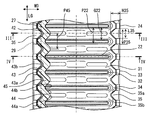
この実施形態は、先行する実施形態を基礎的形態とする変形例である。上記実施形態では、各部のピッチをP22=P35=P45とした。これに代えて、P22×n=P35=P45としてもよい。ただし、nは2以上の自然数である。
この実施形態は、先行する実施形態を基礎的形態とする変形例である。上記実施形態では、タンク部材27から外へ突出するように段差部42、242が設けられる。これに代えて、タンク部材27から内側へ凹むように段差部を設けてもよい。
この実施形態は、先行する実施形態を基礎的形態とする変形例である。上記実施形態では、隣接する2つのチューブ22の間に内峰部44a、244a、344aが位置付けられる。これに代えて、この実施形態では、チューブ22の延長上においてのみ、隣接する2つのチューブ22の間に内峰部444aが位置付けられる。
上記実施形態では、爪および波状壁のピッチは、チューブ22のピッチの1倍または2倍に設定した。これに代えて、3倍、4倍などを採用してもよい。タンク部材27とコアプレート24との連結の強固さを求める場合、爪および波状壁のピッチは、チューブ22のピッチP22の1倍または2倍が望ましい。
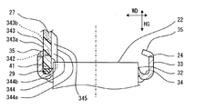
21 コア、 22 チューブ、 23 フィン、
24、25 コアプレート、 26 サイドプレート、
27、28 タンク部材、 29 ガスケット、
31 底板、 32 貫通孔、 33、433 側板、 34 シール面、
35、235 爪、 41、441 縁部、 42 段差部、
43、243、343、443 波状外面、
44、244、344、444 波状内面、
45、245、345、445 波状壁、
446 拡大部。
Claims (7)
- 複数のチューブ(22)と、
複数の前記チューブが接合されたコアプレート(24、25)と、
前記コアプレートに連結されたタンク部材(27、28)とを備え、前記コアプレートの縁と前記タンク部材の縁とがかしめ部によって連結されている熱交換器において、
前記かしめ部は、
前記コアプレートの縁に設けられた複数の爪(35、235)と、
前記タンク部材の開口端に設けられた縁部(441)と、
前記タンク部材に、長さ方向(LG)に沿って波状に設けられた波状壁(445)とを有し、
前記波状壁は、
前記縁部の上の外面に設けられ、交互に配置された複数の外峰部と複数の外谷部とを含む波状外面(443)と、
前記タンク部材の内面に設けられ、交互に配置された複数の内峰部と複数の内谷部とを含む波状内面(444)とを有し、
複数の前記外谷部(443b)は、前記爪を受け入れ可能であるとともに、前記爪が接触する段差部(42)を前記縁部の上に形成しており、
前記内峰部(444a)は、幅方向(WD)における前記外谷部の内側に位置しており、
前記内峰部は、隣り合う前記チューブの間および/または前記チューブの高さ方向(HG)の延長上における前記チューブの間に位置付けられており、
前記内峰部が規定する前記タンク部材の内幅(Wir)は、前記チューブの幅(W22)より小さく、
前記内峰部は、隣り合う前記チューブの間に位置することなく、前記チューブの前記高さ方向(HG)の延長上において前記チューブの間に位置しており、
前記内谷部(444b)は、前記チューブの前記高さ方向の延長上において空間を提供していることを特徴とする熱交換器。 - 前記爪は、先細形状であることを特徴とする請求項1に記載の熱交換器。
- 複数の前記爪のピッチ(P35、P235)および前記波状壁のピッチ(P45、P245)は、複数の前記チューブのピッチ(P22)の自然数(n)倍であることを特徴とする請求項1または請求項2に記載の熱交換器。
- 前記コアプレートは、前記チューブが接合された底板(31)、および前記底板の縁から立ち上がる側板(33)を有し、
前記爪は、前記側板の端に設けられており、
前記爪の前記長さ方向(LG)の寸法(L35、L235)は、隣り合う2つの前記チューブの間の間隔(G22)より小さいことを特徴とする請求項1から請求項3のいずれかに記載の熱交換器。 - さらに、前記縁部と前記コアプレートとの間に設けられたガスケット(29)を備えることを特徴とする請求項1から請求項4のいずれかに記載の熱交換器。
- 前記タンク部材は樹脂製であり、前記コアプレートと前記タンク部材とは、前記かしめ部だけによって連結されていることを特徴とする請求項5に記載の熱交換器。
- 前記爪と前記波状壁とは、前記コアプレートと前記タンク部材との前記長さ方向(LG)に沿って延びる辺にだけ設けられており、
前記コアプレートと前記タンク部材との前記幅方向(WD)に沿って延びる辺には、前記チューブのピッチに依存しない爪と段差部とを含むかしめ部が設けられていることを特徴とする請求項1から請求項6のいずれかに記載の熱交換器。
Priority Applications (4)
| Application Number | Priority Date | Filing Date | Title |
|---|---|---|---|
| JP2013225901A JP6337442B2 (ja) | 2013-10-30 | 2013-10-30 | 熱交換器 |
| PCT/JP2014/005461 WO2015064093A1 (en) | 2013-10-30 | 2014-10-29 | Heat exchanger |
| US15/033,117 US10598444B2 (en) | 2013-10-30 | 2014-10-29 | Heat exchanger |
| EP14800153.0A EP3063490B1 (en) | 2013-10-30 | 2014-10-29 | Heat exchanger |
Applications Claiming Priority (1)
| Application Number | Priority Date | Filing Date | Title |
|---|---|---|---|
| JP2013225901A JP6337442B2 (ja) | 2013-10-30 | 2013-10-30 | 熱交換器 |
Related Child Applications (1)
| Application Number | Title | Priority Date | Filing Date |
|---|---|---|---|
| JP2017223708A Division JP6508297B2 (ja) | 2017-11-21 | 2017-11-21 | 熱交換器 |
Publications (3)
| Publication Number | Publication Date |
|---|---|
| JP2015087055A JP2015087055A (ja) | 2015-05-07 |
| JP2015087055A5 JP2015087055A5 (ja) | 2016-03-31 |
| JP6337442B2 true JP6337442B2 (ja) | 2018-06-06 |
Family
ID=51932561
Family Applications (1)
| Application Number | Title | Priority Date | Filing Date |
|---|---|---|---|
| JP2013225901A Active JP6337442B2 (ja) | 2013-10-30 | 2013-10-30 | 熱交換器 |
Country Status (4)
| Country | Link |
|---|---|
| US (1) | US10598444B2 (ja) |
| EP (1) | EP3063490B1 (ja) |
| JP (1) | JP6337442B2 (ja) |
| WO (1) | WO2015064093A1 (ja) |
Families Citing this family (5)
| Publication number | Priority date | Publication date | Assignee | Title |
|---|---|---|---|---|
| JP6394202B2 (ja) * | 2013-11-27 | 2018-09-26 | 株式会社デンソー | 熱交換器 |
| EP3367039B1 (en) | 2015-10-22 | 2021-04-14 | T.RAD Co., Ltd. | Heat exchanger |
| JP6551293B2 (ja) * | 2016-04-20 | 2019-07-31 | 株式会社デンソー | 熱交換器 |
| FR3062473B1 (fr) * | 2017-01-31 | 2019-04-19 | Valeo Systemes Thermiques | Collecteur pour echangeur de chaleur. |
| JP6992581B2 (ja) * | 2018-02-20 | 2022-01-13 | 株式会社デンソー | 熱交換器 |
Family Cites Families (15)
| Publication number | Priority date | Publication date | Assignee | Title |
|---|---|---|---|---|
| DE2852408B2 (de) | 1978-12-04 | 1981-10-01 | Süddeutsche Kühlerfabrik Julius Fr. Behr GmbH & Co KG, 7000 Stuttgart | Klemmverbindung |
| FR2547403B1 (fr) * | 1983-06-09 | 1985-07-19 | Chausson Usines Sa | Echangeur de chaleur comportant des tubes engages dans une plaque collectrice sertie sur une boite a eau |
| JPH01114697A (ja) * | 1987-10-29 | 1989-05-08 | Nippon Denso Co Ltd | 熱交換器 |
| DE4330865A1 (de) * | 1993-09-11 | 1995-03-16 | Behr Gmbh & Co | Wärmetauscher, insbesondere Kühler, für Kraftfahrzeuge |
| FR2745079B1 (fr) * | 1996-02-20 | 1998-04-10 | Valeo Thermique Moteur Sa | Echangeur de chaleur a boite a fluide brasee, en particulier pour vehicule automobile |
| JP3414171B2 (ja) * | 1996-11-29 | 2003-06-09 | 株式会社デンソー | 熱交換器 |
| JP3797109B2 (ja) * | 2001-01-19 | 2006-07-12 | 株式会社デンソー | 蒸発器 |
| WO2005066568A1 (en) | 2003-12-19 | 2005-07-21 | Valeo, Inc. | Collar rib for heat exchanger tanks |
| JP2005221151A (ja) * | 2004-02-05 | 2005-08-18 | Calsonic Kansei Corp | 熱交換器およびヘッダタンク |
| JP2005326124A (ja) * | 2004-05-17 | 2005-11-24 | Calsonic Kansei Corp | 熱交換器のチューブプレート構造 |
| DE102004033784A1 (de) * | 2004-07-12 | 2006-02-02 | Behr Gmbh & Co. Kg | Wärmetauscher, insbesondere Ladeluftkühler |
| FR2904101B1 (fr) | 2006-07-21 | 2008-09-05 | Valeo Systemes Thermiques | Echangeur de chaleur a collecteur ameliore |
| FR2927412B1 (fr) | 2008-02-13 | 2012-12-21 | Valeo Systemes Thermiques | Plaque collectrice sans gorge |
| DE102011008220A1 (de) | 2010-01-13 | 2012-01-19 | Denso Corporation | Wärmeaustauscher |
| JP2011144973A (ja) * | 2010-01-13 | 2011-07-28 | Denso Corp | 熱交換器 |
-
2013
- 2013-10-30 JP JP2013225901A patent/JP6337442B2/ja active Active
-
2014
- 2014-10-29 WO PCT/JP2014/005461 patent/WO2015064093A1/en active Application Filing
- 2014-10-29 US US15/033,117 patent/US10598444B2/en active Active
- 2014-10-29 EP EP14800153.0A patent/EP3063490B1/en active Active
Also Published As
| Publication number | Publication date |
|---|---|
| JP2015087055A (ja) | 2015-05-07 |
| US10598444B2 (en) | 2020-03-24 |
| EP3063490B1 (en) | 2020-05-13 |
| WO2015064093A1 (en) | 2015-05-07 |
| EP3063490A1 (en) | 2016-09-07 |
| US20160258693A1 (en) | 2016-09-08 |
Similar Documents
| Publication | Publication Date | Title |
|---|---|---|
| JP6337442B2 (ja) | 熱交換器 | |
| JP5856068B2 (ja) | 熱交換器 | |
| US8910704B2 (en) | Heat exchanger | |
| EP1722184A2 (en) | Coupling structure of heat transfer plate and gasket of plate type heat exchanger | |
| US20120118548A1 (en) | Plate Heat Exchanger | |
| JP5952259B2 (ja) | 熱交換器 | |
| JP5476585B2 (ja) | 冷却器 | |
| EP2458312B1 (en) | Heat exchanger for an internal combustion engine | |
| JP6938669B2 (ja) | 自動車両用の熱交換器 | |
| US6662859B2 (en) | Cooler for power electronics | |
| US10837707B2 (en) | Heat exchanger | |
| JP2009146948A (ja) | 熱交換器用フィンおよびその製造方法 | |
| US20180094870A1 (en) | Heat exchanger | |
| JP2018028431A (ja) | 熱交換器 | |
| US20210123690A1 (en) | Heat Exchange Tube, Heat Exchange Tube Manufacturing Method, and Heat Exchanger | |
| US10281222B2 (en) | Heat exchanger | |
| CN112146484B (zh) | 板式换热器 | |
| CN110118504B (zh) | 扁平管 | |
| JP7230020B2 (ja) | 熱交換器及び熱交換器の製造方法 | |
| JP6764765B2 (ja) | 伝熱部材 | |
| JP4341490B2 (ja) | 熱交換器 | |
| JP2019190674A (ja) | 熱交換器 | |
| CN211900771U (zh) | 发动机用高性能散热器 | |
| CN211178077U (zh) | 一种欧姆型异形封条散热器 | |
| JP2007170747A (ja) | 熱交換器 |
Legal Events
| Date | Code | Title | Description |
|---|---|---|---|
| A521 | Request for written amendment filed |
Free format text: JAPANESE INTERMEDIATE CODE: A523 Effective date: 20160216 |
|
| A621 | Written request for application examination |
Free format text: JAPANESE INTERMEDIATE CODE: A621 Effective date: 20160913 |
|
| A131 | Notification of reasons for refusal |
Free format text: JAPANESE INTERMEDIATE CODE: A131 Effective date: 20170822 |
|
| A521 | Request for written amendment filed |
Free format text: JAPANESE INTERMEDIATE CODE: A523 Effective date: 20171121 |
|
| TRDD | Decision of grant or rejection written | ||
| A01 | Written decision to grant a patent or to grant a registration (utility model) |
Free format text: JAPANESE INTERMEDIATE CODE: A01 Effective date: 20180410 |
|
| A61 | First payment of annual fees (during grant procedure) |
Free format text: JAPANESE INTERMEDIATE CODE: A61 Effective date: 20180423 |
|
| R150 | Certificate of patent or registration of utility model |
Ref document number: 6337442 Country of ref document: JP Free format text: JAPANESE INTERMEDIATE CODE: R150 |
|
| R250 | Receipt of annual fees |
Free format text: JAPANESE INTERMEDIATE CODE: R250 |
|
| R250 | Receipt of annual fees |
Free format text: JAPANESE INTERMEDIATE CODE: R250 |
|
| R250 | Receipt of annual fees |
Free format text: JAPANESE INTERMEDIATE CODE: R250 |