JP6337442B2 - Heat exchanger - Google Patents
Heat exchanger Download PDFInfo
- Publication number
- JP6337442B2 JP6337442B2 JP2013225901A JP2013225901A JP6337442B2 JP 6337442 B2 JP6337442 B2 JP 6337442B2 JP 2013225901 A JP2013225901 A JP 2013225901A JP 2013225901 A JP2013225901 A JP 2013225901A JP 6337442 B2 JP6337442 B2 JP 6337442B2
- Authority
- JP
- Japan
- Prior art keywords
- tubes
- tank member
- edge
- claw
- tube
- Prior art date
- Legal status (The legal status is an assumption and is not a legal conclusion. Google has not performed a legal analysis and makes no representation as to the accuracy of the status listed.)
- Active
Links
Images


Classifications
-
- F—MECHANICAL ENGINEERING; LIGHTING; HEATING; WEAPONS; BLASTING
- F28—HEAT EXCHANGE IN GENERAL
- F28F—DETAILS OF HEAT-EXCHANGE AND HEAT-TRANSFER APPARATUS, OF GENERAL APPLICATION
- F28F9/00—Casings; Header boxes; Auxiliary supports for elements; Auxiliary members within casings
- F28F9/02—Header boxes; End plates
- F28F9/0219—Arrangements for sealing end plates into casing or header box; Header box sub-elements
- F28F9/0224—Header boxes formed by sealing end plates into covers
- F28F9/0226—Header boxes formed by sealing end plates into covers with resilient gaskets
-
- F—MECHANICAL ENGINEERING; LIGHTING; HEATING; WEAPONS; BLASTING
- F28—HEAT EXCHANGE IN GENERAL
- F28D—HEAT-EXCHANGE APPARATUS, NOT PROVIDED FOR IN ANOTHER SUBCLASS, IN WHICH THE HEAT-EXCHANGE MEDIA DO NOT COME INTO DIRECT CONTACT
- F28D1/00—Heat-exchange apparatus having stationary conduit assemblies for one heat-exchange medium only, the media being in contact with different sides of the conduit wall, in which the other heat-exchange medium is a large body of fluid, e.g. domestic or motor car radiators
- F28D1/02—Heat-exchange apparatus having stationary conduit assemblies for one heat-exchange medium only, the media being in contact with different sides of the conduit wall, in which the other heat-exchange medium is a large body of fluid, e.g. domestic or motor car radiators with heat-exchange conduits immersed in the body of fluid
- F28D1/04—Heat-exchange apparatus having stationary conduit assemblies for one heat-exchange medium only, the media being in contact with different sides of the conduit wall, in which the other heat-exchange medium is a large body of fluid, e.g. domestic or motor car radiators with heat-exchange conduits immersed in the body of fluid with tubular conduits
- F28D1/053—Heat-exchange apparatus having stationary conduit assemblies for one heat-exchange medium only, the media being in contact with different sides of the conduit wall, in which the other heat-exchange medium is a large body of fluid, e.g. domestic or motor car radiators with heat-exchange conduits immersed in the body of fluid with tubular conduits the conduits being straight
- F28D1/0535—Heat-exchange apparatus having stationary conduit assemblies for one heat-exchange medium only, the media being in contact with different sides of the conduit wall, in which the other heat-exchange medium is a large body of fluid, e.g. domestic or motor car radiators with heat-exchange conduits immersed in the body of fluid with tubular conduits the conduits being straight the conduits having a non-circular cross-section
- F28D1/05366—Assemblies of conduits connected to common headers, e.g. core type radiators
-
- F—MECHANICAL ENGINEERING; LIGHTING; HEATING; WEAPONS; BLASTING
- F28—HEAT EXCHANGE IN GENERAL
- F28F—DETAILS OF HEAT-EXCHANGE AND HEAT-TRANSFER APPARATUS, OF GENERAL APPLICATION
- F28F1/00—Tubular elements; Assemblies of tubular elements
- F28F1/10—Tubular elements and assemblies thereof with means for increasing heat-transfer area, e.g. with fins, with projections, with recesses
- F28F1/12—Tubular elements and assemblies thereof with means for increasing heat-transfer area, e.g. with fins, with projections, with recesses the means being only outside the tubular element
- F28F1/14—Tubular elements and assemblies thereof with means for increasing heat-transfer area, e.g. with fins, with projections, with recesses the means being only outside the tubular element and extending longitudinally
- F28F1/22—Tubular elements and assemblies thereof with means for increasing heat-transfer area, e.g. with fins, with projections, with recesses the means being only outside the tubular element and extending longitudinally the means having portions engaging further tubular elements
-
- F—MECHANICAL ENGINEERING; LIGHTING; HEATING; WEAPONS; BLASTING
- F28—HEAT EXCHANGE IN GENERAL
- F28F—DETAILS OF HEAT-EXCHANGE AND HEAT-TRANSFER APPARATUS, OF GENERAL APPLICATION
- F28F21/00—Constructions of heat-exchange apparatus characterised by the selection of particular materials
- F28F21/06—Constructions of heat-exchange apparatus characterised by the selection of particular materials of plastics material
- F28F21/062—Constructions of heat-exchange apparatus characterised by the selection of particular materials of plastics material the heat-exchange apparatus employing tubular conduits
-
- F—MECHANICAL ENGINEERING; LIGHTING; HEATING; WEAPONS; BLASTING
- F28—HEAT EXCHANGE IN GENERAL
- F28F—DETAILS OF HEAT-EXCHANGE AND HEAT-TRANSFER APPARATUS, OF GENERAL APPLICATION
- F28F2225/00—Reinforcing means
- F28F2225/08—Reinforcing means for header boxes
-
- F—MECHANICAL ENGINEERING; LIGHTING; HEATING; WEAPONS; BLASTING
- F28—HEAT EXCHANGE IN GENERAL
- F28F—DETAILS OF HEAT-EXCHANGE AND HEAT-TRANSFER APPARATUS, OF GENERAL APPLICATION
- F28F2275/00—Fastening; Joining
- F28F2275/12—Fastening; Joining by methods involving deformation of the elements
-
- F—MECHANICAL ENGINEERING; LIGHTING; HEATING; WEAPONS; BLASTING
- F28—HEAT EXCHANGE IN GENERAL
- F28F—DETAILS OF HEAT-EXCHANGE AND HEAT-TRANSFER APPARATUS, OF GENERAL APPLICATION
- F28F2275/00—Fastening; Joining
- F28F2275/12—Fastening; Joining by methods involving deformation of the elements
- F28F2275/122—Fastening; Joining by methods involving deformation of the elements by crimping, caulking or clinching
Description
ここに開示される発明は、熱交換器に関する。 The invention disclosed herein relates to a heat exchanger.
特許文献1、2および3は、熱交換器を開示する。これらの熱交換器は、タンク部を有する。タンク部は、コアプレートと、タンク部材とによって形成される。タンク部材とコアプレートとは、かしめ部によって連結されている。かしめ部は、タンク部材の縁と、コアプレートの縁とによって提供される。コアプレートの縁は、ハウジングの縁を包み込むように変形加工されている。コアプレートの縁には、爪と呼ばれる曲げ可能な部位が設けられる。タンク部材の縁には、爪を受ける段差部が設けられる。爪は、タンク部材の縁を抱え込むように曲げられている。
従来の構成では、タンク部の壁とチューブとの干渉を避けるために、チューブの端面から幅方向へ離れた位置において、タンク部とコアプレートとがかしめ部によって固定されている。さらに、タンク部の壁の厚さは、耐久性などの性能の要請から所定の厚さに設定する必要がある。このため、熱交換器の端部に形成されるタンク部の幅を小さくすることが困難である。上述の観点において、または言及されていない他の観点において、熱交換器にはさらなる改良が求められている。 In the conventional configuration, in order to avoid interference between the wall of the tank portion and the tube, the tank portion and the core plate are fixed by the caulking portion at a position away from the end face of the tube in the width direction. Furthermore, it is necessary to set the wall thickness of the tank part to a predetermined thickness in view of performance requirements such as durability. For this reason, it is difficult to reduce the width of the tank portion formed at the end of the heat exchanger. In view of the above, or other aspects not mentioned, there is a need for further improvements in heat exchangers.
発明の目的のひとつは、タンク部の幅が小さい熱交換器を提供することである。 One of the objects of the invention is to provide a heat exchanger having a small tank section.
発明の目的の他のひとつは、かしめ部における深い抱え込みが可能な熱交換器を提供することである。 Another object of the invention is to provide a heat exchanger that can be deeply held in the caulking portion.
発明の目的の他のひとつは、かしめ部における深い抱え込みと、タンク部の小さい幅とを両立した熱交換器を提供することである。 Another object of the invention is to provide a heat exchanger that achieves both a deep holding in the caulking portion and a small width in the tank portion.
発明の目的の他のひとつは、タンク部の幅がチューブの幅に近い熱交換器を提供することである。 Another object of the invention is to provide a heat exchanger in which the width of the tank portion is close to the width of the tube.
ここに開示される発明は上記目的を達成するために以下の技術的手段を採用する。なお、特許請求の範囲およびこの項に記載した括弧内の符号は、後述する実施形態に記載の具体的手段との対応関係を示すものであって、発明の技術的範囲を限定するものではない。 The invention disclosed herein employs the following technical means to achieve the above object. Note that the reference numerals in parentheses described in the claims and in this section indicate the correspondence with the specific means described in the embodiments described later, and do not limit the technical scope of the invention. .
開示される発明のひとつにより熱交換器が提供される。発明は、複数のチューブ(22)と、複数のチューブが接合されたコアプレート(24、25)と、コアプレートに連結されたタンク部材(27、28)とを備え、コアプレートの縁とタンク部材の縁とがかしめ部によって連結されている熱交換器において、かしめ部は、コアプレートの縁に設けられた複数の爪(35、235)と、タンク部材の開口端に設けられた縁部(441)と、タンク部材に、長さ方向(LG)に沿って波状に設けられた波状壁(445)とを有し、波状壁は、縁部の上の外面に設けられ、交互に配置された複数の外峰部と複数の外谷部とを含む波状外面(443)と、タンク部材の内面に設けられ、交互に配置された複数の内峰部と複数の内谷部とを含む波状内面(444)とを有し、複数の外谷部(443b)は、爪を受け入れ可能であるとともに、爪が接触する段差部(42)を縁部の上に形成しており、内峰部(444a)は、幅方向(WD)における外谷部の内側に位置しており、内峰部は、隣り合うチューブの間および/またはチューブの高さ方向(HG)の延長上におけるチューブの間に位置付けられており、内峰部が規定するタンク部材の内幅(Wir)は、チューブの幅(W22)より小さく、内峰部は、隣り合うチューブの間に位置することなく、チューブの高さ方向(HG)の延長上においてチューブの間に位置しており、内谷部は、チューブの高さ方向の延長上において空間を提供していることを特徴とする。 One of the disclosed inventions provides a heat exchanger. The invention includes a plurality of tubes (22), a core plate (24, 25) to which the plurality of tubes are joined, and tank members (27, 28) connected to the core plate. In the heat exchanger in which the edge of the member is connected by the caulking part, the caulking part includes a plurality of claws (35, 235) provided at the edge of the core plate and the edge provided at the opening end of the tank member. ( 441 ) and wavy walls ( 445 ) provided in a wave shape along the length direction (LG) in the tank member, and the wavy walls are provided on the outer surface above the edge and are alternately arranged. A corrugated outer surface ( 443 ) including a plurality of outer ridge portions and a plurality of outer valley portions, and a plurality of inner ridge portions and a plurality of inner valley portions provided on the inner surface of the tank member and arranged alternately and a wavy inner surface (444), a plurality of outer valleys (44 b), together can accept a nail, forms stepped portion pawl contacts (42) on the edge, Uchimine portion (444a), the outer valley in the width direction (WD) The inner ridge is located between the adjacent tubes and / or between the tubes in the height direction (HG) extension of the tube, and the inner ridge is defined by the inner ridge. The inner width (Wir) is smaller than the tube width (W22), and the inner ridge portion is located between the tubes on the extension in the tube height direction (HG) without being located between adjacent tubes. The inner valley portion is characterized by providing a space on the extension in the height direction of the tube .
この構成によると、外谷部によって爪が受け入れられる。さらに、外谷部は、爪が接触する段差部を縁部の上に形成する。外谷部の内側に内峰部が位置することにより、タンク部材の壁の厚さを適切に設定することが可能である。内峰部は、隣り合うチューブの間および/またはチューブの延長上におけるチューブの間に位置している。これにより、内峰部とチューブとの過剰な干渉が回避される。 According to this configuration, the nail is received by the outer valley portion. Further, the outer valley portion forms a stepped portion on the edge portion where the nail contacts. By positioning the inner ridge portion on the inner side of the outer valley portion, it is possible to appropriately set the thickness of the wall of the tank member. Inner ridges are located between adjacent tubes and / or between tubes on the extension of the tube. This avoids excessive interference between the inner ridge and the tube.
図面を参照しながら、ここに開示される発明を実施するための複数の形態を説明する。各形態において、先行する形態で説明した事項に対応する部分には同一の参照符号を付して重複する説明を省略する場合がある。また、後続の実施形態においては、先行する実施形態で説明した事項に対応する部分に百以上の位だけが異なる参照符号を付することにより対応関係を示し、重複する説明を省略する場合がある。各形態において、構成の一部のみを説明している場合は、構成の他の部分については他の形態の説明を参照し適用することができる。 A plurality of modes for carrying out the invention disclosed herein will be described with reference to the drawings. In each embodiment, portions corresponding to the matters described in the preceding embodiment may be denoted by the same reference numerals and redundant description may be omitted. Further, in the following embodiments, the correspondence corresponding to the matters corresponding to the matters described in the preceding embodiments is indicated by adding reference numerals that differ only by one hundred or more, and redundant description may be omitted. . In each embodiment, when only a part of the structure is described, the other parts of the structure can be applied with reference to the description of the other forms.
(第1実施形態)
図1において、熱交換器10は、内部流体と外部流体との間の熱交換を提供する。熱交換器10は、熱システム11の一部品である。熱システム11は、高温の内部流体、または低温の内部流体を供給する熱機器(TS)12を備える。
(First embodiment)
In FIG. 1, a
外部流体の一例は空気である。内部流体の一例は、液体である。熱交換器10は、例えば、熱機器12から供給される廃熱を大気へ放出するための放熱器として機能する。また、熱交換器10は、熱機器12から供給される低温の液体によって空気を冷却する冷却器として機能する。
An example of the external fluid is air. An example of the internal fluid is a liquid. The heat exchanger 10 functions as a radiator for releasing waste heat supplied from the
熱システム11の一例は車両に搭載された冷却液循環システムである。この場合、熱機器12は内燃機関またはインバータなどの発熱機器である。典型的な一例では、熱交換器10は、内燃機関を冷却するための冷却液から車両外の空気へ放熱するための車両用ラジエータである。
An example of the
熱交換器10は、熱交換のためのコア21を備える。コア21は、高さ方向HGと長さ方向LGとに沿って広がり、幅方向(厚さ方向)WDに薄い板状である。コア21は、複数のチューブ22、複数のフィン23、コアプレート24、25、およびガスケット29を有する。コア21を構成する部品は、互いにろう付けによって接合されている。熱交換器10は、タンク部材27、28を備える。
The
コア21は、複数のチューブ22を備える。それぞれのチューブ22は、アルミ合金等の金属製である。チューブ22は、その両端において開口する管である。チューブ22は、高さ方向HGに沿って長く延びている。チューブ22の長手方向は、高さ方向HGに対応する。チューブ22は、長手方向に垂直な断面が扁平な形状である。図示の例では、チューブ22は、長円形断面をもつ扁平管である。チューブ22の端面および/または断面の長手方向は、幅方向WDに対応する。
The
複数のチューブ22は、互いに平行に配列されている。複数のチューブ22は、それらの平らな面が平行になるように配置されている。複数のチューブ22は、互いに所定の距離だけ離れて配置されている。複数のチューブ22の内部には、内部流体の通路が形成される。複数のチューブ22の間には、外部流体の通路が形成される。
The plurality of
コア21は、複数のフィン23を有する。それぞれのフィン23は、アルミ合金等の金属製である。フィン23は、波形に成形された薄いアルミ合金板である。フィン23は、コルゲートフィンとも呼ばれる。フィン23は、隣接して位置付けられた2つのチューブ22の間に配置されている。フィン23は、チューブ22と熱的に接触する。フィン23は、チューブ22の外側における熱交換、すなわち空気との熱交換を促進する。
The
コア21は、コアプレート24、25を有する。コアプレート24、25は、アルミ合金等の金属製である。コアプレート24、25は、細長く、浅いカップ状の部材である。コアプレート24、25は、角が丸い四角形の開口をもつ。コアプレート24、25の開口の縁は、後述のタンク部材27、28の開口端を内部に受け入れることが可能な大きさをもつ。コアプレート24、25は、幅方向WDの寸法より、長さ方向LGの寸法が大きい。コアプレート24、25は、長さ方向LGに沿って細長く延びている。コアプレート24、25の幅方向WDの寸法は、チューブ22の幅方向WDの寸法に近いが、やや大きい。
The
一方のコアプレート24は、複数のチューブ22の一方の端部に位置付けられている。複数のチューブ22は、コアプレート24を貫通するように配置されている。複数のチューブ22は、コアプレート24にろう付けによって接合され、固定されている。他方のコアプレート25は、複数のチューブ22の他方の端部に位置付けられている。複数のチューブ22は、コアプレート25を貫通するように配置されている。複数のチューブ22は、コアプレート25にろう付けによって接合され、固定されている。
One
コア21は、サイドプレート26を有する。サイドプレート26は、アルミ合金等の金属製である。サイドプレート26は、コア21の端部に配置されている。サイドプレート26は、積層的に配置された複数のチューブ22と複数のフィン23との端部に配置されている。サイドプレート26は、コア21の強度を向上させる。
The
タンク部材27、28は樹脂製である。タンク部27、28は、樹脂タンクとも呼ばれる。タンク部材27、28は、細長いカップ状の部材である。タンク部材27、28は、角が丸い四角形の開口をもつ。タンク部材27、28の開口の縁は、コアプレート24、25の開口の内部に嵌め込むことが可能な大きさをもつ。タンク部材27、28は、幅方向WDの寸法より、長さ方向LGの寸法が大きい。タンク部材27、28は、長さ方向LGに沿って細長く延びている。タンク部材27、28の幅方向WDの寸法は、チューブ22の幅方向WDの寸法に近いが、やや大きい。
The
タンク部材27、28は、コア21に連結されることによってタンク部を区画形成する。より具体的には、タンク部材27、28は、コアプレート24、25と連結されることによってタンク部を区画形成する。タンク部は、内部流体を複数のチューブ22に分配する分配タンクおよび/または複数のチューブ22から内部流体を集める集合タンクを提供する。タンク部材27、28は、任意の位置に、内部流体の入口および出口を有する。
The
コアプレート24、25とタンク部材27、28とは、コアプレート24、25によってタンク部材27、28の開口を覆うように位置付けられ、連結されている。コアプレート24、25とタンク部材27、28とは、コアプレート24、25の外周部の縁と、タンク部材27、28の開口の縁とによって形成されるかしめ部によって連結されている。コアプレート24、25とタンク部材27、28とは、かしめ部だけによって連結されている。
The
かしめ部を形成するために、コアプレート24、25は、タンク部材27、28の開口の縁を受け入れる収容部を有する。かしめ部を形成するために、コアプレート24、25は、タンク部材27、28の開口の縁を抱え込むための複数の爪を有する。かしめ部を形成するために、タンク部材27、28は、コアプレート24、25の複数の爪を受け入れ、複数の爪と当接する段差部を有する。コアプレート24、25の複数の爪は、タンク部材27、28の縁を抱え込み、段差部と当接するように変形させられている。これにより、コアプレート24、25とタンク部材27、28とは、連結されている。
In order to form the caulking portion, the
コアプレート24とタンク部材27とが形成する上タンク部と、コアプレート25とタンク部材28とが形成する下タンク部とは同様の形状を有している。以下の説明では、主として上タンク部について説明する。
The upper tank part formed by the
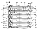
図2は、図3および図4にII−II線によって示され、水平面HPに平行な断面を示している。図3は、垂直面VPに平行であって、図2にIII−III線によって示される断面を示している。図3は、チューブ22がない位置の断面である。図4は、垂直面VPに平行であって、図2にVI−VI線によって示される断面を示している。図4は、チューブ22がある位置の断面である。図2−図4において、左半部にはタンク部材27を含む断面が図示され、右半部にはタンク部材27を取り除いた断面が図示されている。
FIG. 2 shows a cross section indicated by the line II-II in FIGS. 3 and 4 and parallel to the horizontal plane HP. FIG. 3 shows a cross section parallel to the vertical plane VP and indicated by the line III-III in FIG. FIG. 3 is a cross section of a position where the
図2−図4において、熱交換器10は、ガスケット29を有する。ガスケット29は、ゴム製または樹脂製である。ガスケット29は、四辺形の環状である。ガスケット29は、コアプレート24とタンク部材27との間に配置されている。ガスケット29は、タンク部材27の開口部の端面と、コアプレート24との間に配置されている。ガスケット29は、コアプレート24とタンク部材27との間をシールする。ガスケット29は、長さ方向LGに沿って真っ直ぐに延びている。ガスケット29は、コアプレート24およびタンク部材27から独立した部品として提供することができる。ガスケット29は、コアプレート24またはタンク部材27に接着等の接合手段によって一体化されていてもよい。
2 to 4, the
コアプレート24は、板状の部材である。コアプレート24は、板を所定の形状に切断し、曲げることによって形成されている。コアプレート24は、チューブ22が接合された底板31、および底板31の縁から立ち上がる側板33を有する。コアプレート24は、側板33の端に設けられた爪35を有する。
The
コアプレート24は、細長い板状の底板31を有する。底板31には、チューブ22を貫通させるための貫通孔32が設けられている。底板31には、多数の凹凸形状が形成されている。例えば、貫通孔32は、コア21からタンク部内に向けて隆起する凸形状の頂部に開設されている。凹凸形状は、底板31の強度を高めるために貢献する。凹凸形状は、貫通孔32とチューブ22とのろう付け面積の増加に貢献する。
The
コアプレート24は、底板31の4辺に位置付けられた側板33を有する。側板33は、底板31の4辺から垂直に立ち上がるように設けられている。底板31と側板33とによって、タンク部材27を受け入れるための収容部が区画形成される。側板33は、コアプレート24の長手方向の辺に設けられている。さらに、側板33は、コアプレート24の短手方向の辺にも設けられている。短手方向の辺は、図1のサイドプレート26の上に位置付けられている。
The
コアプレート24は、底板31の縁に沿って環状のシール面34を有する。シール面34上にガスケット29が配置されている。シール面34は、底板31に形成された凹凸形状と、側板33との間に溝状に区画されている。
The
コアプレート24は、複数の爪35を有する。複数の爪35は、側板33の縁から延び出している。爪35は、側板33から側板33の高さ方向へ延び出すとともに、側板33より内側へ延び出している。爪35は、側板33より内側へ延び出すように曲げられている。これにより、爪35は、タンク部材27の縁を抱え込む。
The
爪35は、側板33から先端に向けて徐々に細くなる先細形状をもつ。爪35は、2つの斜辺35a、35bをもつ。爪35は、先端が三角形の細長い形状をもつ。爪35の形状は、舌状とも呼ぶことができる。
The
爪35の長さ(高さ)H35は、爪35の先端が、チューブ22の配列領域の近傍に到達するように設定されている。爪35の長さH35は、爪35の先端が、チューブ35の配列領域の中に到達するように設定されてもよい。爪35の長さH35は、垂直方向に見て、すなわち図2において、爪35の先端が、隣接する2つのチューブ22の間の領域の中に到達するように設定されてもよい。
The length (height) H35 of the
爪35は、間隔G22より細い部分を有している。爪35の先端部の幅(長さ)は、複数のチューブ22の間隔G22より小さい。爪35の基端部における長さ方向LGの寸法L35(幅または長さと呼ばれる)は、隣り合う2つのチューブ22の間の間隔G22より小さい。細い爪は、タンク部材27とチューブ22との干渉回避を容易にする。チューブ22と爪35とを水平面HP上に投影した場合に、チューブ22と爪35とは、幅方向WDに関して互いに重複することがないように形成され、配置されている。爪35の先端を含む三角形の先端領域は、幅方向WDに関してチューブ22と重複することがない。代替的に、幅L35は、間隔G22より大きく設定することができる。この代替例においても、先細の爪35は、間隔G22より細い部分を有している。
The nail | claw 35 has a part thinner than the space | interval G22. The width (length) of the tip of the
チューブ22と爪35とを水平面HP上に投影した場合に、爪35は、隣接する2つのチューブ22の間に対応する位置にだけ設けられている。言い換えると、チューブ22の端面および/または断面の長手方向、すなわち幅方向WDの延長上には、爪35は設けられていない。
When the
複数のチューブ22の配置規則と、複数の爪35の配置規則とは、互いに同期的である。複数のチューブ22の配置規則と、複数の爪35の配置規則とは、爪35の先端と、チューブ22とが、幅方向WDに沿って一直線上に整列することがないようにずれている。複数のチューブ22のピッチP22は、一定である。複数の爪35のピッチP35は、一定である。複数の爪35のピッチP35は、複数のチューブ22のピッチP22に等しい。爪35のピッチP35と、チューブ22のピッチP22との関係は、P35=P22×nである。nは自然数である。この例では、n=1である。
The arrangement rule of the plurality of
タンク部材27は、開口部の縁部41を有する。縁部41は、四辺形の環状である。縁部41は、ガスケット29と接触する端面を提供する。この端面は、長さ方向LGに沿って真っ直ぐに延びる。ガスケット29は、縁部41とコアプレート24との間に設けられている。縁部41は、底板31の縁と、側板33と、爪35とによって抱え込まれる。端面と反対側において、縁部41は、爪35を受ける受け面を提供する。受け面は、後述する段差部42によって提供されている。縁部41は、かしめ部を構成する一部分である。
The
タンク部材27は、複数の段差部42を有する。段差部42は、タンク部材27の外面に形成されている。段差面42は、チューブ22の端面より高さ方向HGに離れた位置に設けられている。段差面42は、幅方向WDに関して、チューブ22およびその長手方向延長領域より、外側に位置して設けられている。
The
段差部42は、爪35を受け入れることができる凹部によって提供されている。段差部42は、爪35が当接する受け面を提供する。段差部42は、タンク部材27の開口端の縁に、爪35によって抱え込まれる突出部を提供する。段差部42に爪35が当接することにより、かしめ部が形成される。この結果、コアプレート24とタンク部材27とが連結される。
The
タンク部材27は、波状外面43を有する。波状外面43は、複数の凹部、すなわち複数の段差部42を提供する。波状外面43は、タンク部材27の外面に形成されている。波状外面43は、縁部41より上に形成されている。波状外面43は、縁部41より内側へ凹むことによって複数の段差部42を提供する。
The
波状外面43は、外峰部43aと外谷部43bとを有する。外峰部43aが規定する幅方向WDの外幅Worは、縁部41が規定する幅と等しい。外谷部43bは、縁部41より内側へ凹んでいる。外谷部43bは、段差部42を区画する。外谷部43bは、爪35を受け入れ可能な深さを提供する。よって、複数の外谷部43bは、爪35を受け入れ可能であるとともに、接触する段差部42を縁部41の上に爪が形成している。
The waved
波状外面43は、タンク部材27の高さ方向の一部範囲だけに形成されている。波状外面43は、縁部41から高さ方向HGに沿って所定高さにわたって延びている。外峰部43aと外谷部43bとは、高さ方向HGに沿って延びている。外峰部43aは、徐々に低くなる。外峰部43aは、縁部41から所定距離離れた位置において外谷部43bと同じ高さになる。外谷部43bは、タンク部材27の上部と同じ幅を有している。
The waved
タンク部材27は、波状内面44を有する。波状内面44は、タンク部材27の内面に形成されている。波状内面44は、縁部41の内側にも形成されている。波状内面44は、縁部41より内側へ突出する。
The
波状内面44は、内峰部44aと内谷部44bとを有する。内峰部44aの深さは、タンク部材27の上部の内面に等しい。内谷部44bは、縁部41の内面と等しい。
The waved
波状内面44は、タンク部材27の高さ方向HGの一部範囲だけに形成されている。波状内面44は、幅方向WDにおける波状外面43の内側に形成されている。波状内面44は、高さ方向HGに関して、波状外面43より広い範囲にわたって形成されている。波状内面44は、縁部41から高さ方向HGに沿って所定高さにわたって延びている。内峰部44aと内谷部44bとは、高さ方向HGに沿って延びている。内峰部44aの一部は、長さ方向に関して、チューブ22と重複するように位置付けられている。図3および図4においては、内峰部44aの下端角部が、図示方向に関して、すなわち長さ方向LGに関してチューブ22の角部と重複するように位置付けられている。さらに、内峰部44a部は、チューブ22の延長上においても、そこにチューブがあれば、チューブ22と重複するように位置付けられている。内峰部44aは、隣り合う2つのチューブ22の間、およびその延長上に位置付けられる。これにより、内峰部44aは、段差部42の内側に必要な厚さの壁を設けることを可能とする。しかも、内峰部44aは、チューブ22との干渉を回避する。
The waved
内谷部44bは、縁部41から離れるにつれて、徐々に浅くなる。内谷部44bは、縁部41から所定距離離れた位置において内峰部44aと同じ幅になる。波状内面44は、チューブ22の端面の延長上において、チューブ22の端面上に覆い被さるように延びている。
The
図2に図示されるように、波状外面43と波状内面44とは、それらの間に波状壁45を形成する。言い換えると、波状壁45は、縁部41の上の外面に設けられ、交互に配置された複数の外峰部43aと複数の外谷部43bとを含む波状外面43を有する。波状壁45は、タンク部材27、28の内面に設けられ、交互に配置された複数の内峰部44aと複数の内谷部44bとを含む波状内面44を有する。
As shown in FIG. 2, the waved
外峰部43aと内谷部44bとは、幅方向WDに沿って整列して位置付けられている。外谷部43bと内峰部44aとは、幅方向WDに沿って整列して位置付けられている。波状壁45は、その外側において爪35を受け入れる外谷部43bを提供することによって、段差部42を形成する。また、波状壁45は、その内側においてチューブ22との干渉を抑制する内谷部44bと、チューブ22の間にまで延び出した内峰部44aとを提供する。さらに、波状壁45は、タンク部材27の剛性を高める。波状壁45は、縁部41の変形を抑制するために貢献する。
The
波状壁45のピッチP45は、爪35のピッチP35に等しい。波状壁45のピッチP45は、チューブ22のピッチP22に等しい。波状壁45のピッチP45と、チューブ22のピッチP22との関係は、P45=P22×nである。nは自然数である。この例では、n=1である。ピッチP45は、段差部42、波状外面43、または波状内面44のピッチでもある。
The pitch P45 of the waved
図3に図示されるように、内谷部44bが規定する内幅Wibは、チューブ22の幅W22よりわずかに大きい。複数の内谷部44bの一部は、チューブ22の端部に接触することがある。内谷部44bと、チューブ22の端部との間には、微小な隙間が形成されることが望ましい。内谷部44bは、チューブ22とタンク部材27との間の過剰な干渉を回避する。内谷部44bの高さ方向HGの長さは、チューブ22との干渉を回避できるように、チューブ22の突出量より長い。内谷部44bは、チューブ22の幅方向WDの外側に位置して、その中にチューブ22を受け入れている。
As illustrated in FIG. 3, the inner width Wib defined by the
内峰部44aが規定する内幅Wirは、タンク部材27の上部が規定する内部間隔と等しい。内幅Wirは、チューブ22の幅W22より小さい。すなわち、内峰部44aは、隣り合う2つのチューブ22の間に位置している。さらに、内峰部44aは、チューブ22の高さ方向HGの延長上において、2つのチューブ22の間に位置している。この構成によると、タンク部材27の内幅Wirをチューブ22の幅W22より狭く設定することができる。この結果、タンク部材27の壁に適切な厚さを与えながら、タンク部材27の外幅を小さくすることができる。
The inner width Wir defined by the
内峰部44aは、幅方向WDにおける外谷部43bの内側に形成されている。外谷部43bは、段差部42を提供するために、縁部41より内側へ凹んでいる。内峰部44aは、幅方向WDに関して外谷部43bの内側において、タンク部材27の壁の必要な厚さを維持することを可能とする。
The
この熱交換器10では、コアプレート24とタンク部材27とを連結するかしめ部は、コアプレート24の縁に設けられた複数の爪35と、タンク部材27の開口端に設けられた縁部41とを有する。さらに、かしめ部は、タンク部材27に長さ方向LGに沿って波状に設けられた波状壁45を有する。
In the
コアプレート24の幅方向WDの両側の縁は、対称形に形成される。タンク部材27の幅方向WDの両側の縁は、対称形に形成される。
The edges on both sides of the
図1に戻り、爪35と波状壁45とは、コアプレート24とタンク部材27との長さ方向LGに沿って延びる辺にだけ設けられている。コアプレート24とタンク部材27との幅方向WDに沿って延びる辺には、チューブ22のピッチに依存しない爪と段差部とを含むかしめ部が設けられている。これらの爪の形状は、チューブ22のピッチに依存することなく形成されている。これらの爪は、例えば長方形である。短手方向の側板33上にも爪35と同形状の爪を設けてもよい。よって、好適な形態では、コアプレート24は、少なくとも長さ方向LGに沿って延びる辺に複数の爪35を備える。
Returning to FIG. 1, the
コアプレート24を準備する工程において、爪35は側板33と平行に立ち上がるように形成される。次に、組合せ工程において、コアプレート24とタンク部材27とが組み合わせられる。コアプレート24内にタンク部材27が挿し込まれる。この後に、かしめ工程が実施される。かしめ工程では、複数の爪35が、図示される形状に向けて曲げられる。複数の爪35は、タンク部材27の段差部42の上に覆い被さるように、さらに段差部42に当接するように曲げられる。これにより、かしめ部が形成される。この結果、コアプレート24とタンク部材27とが連結され、タンク部が区画形成される。なお、コアプレート25とタンク部材28とも、同様の製造方法によって連結される。
In the step of preparing the
この構成によると、外谷部43bによって爪35が受け入れられる。さらに、外谷部43bは、爪35が接触する段差部42を縁部41の上に形成する。外谷部43bの内側には内峰部44aが設けられている。内峰部44aは、隣り合うチューブ22の間に位置している。これにより、内峰部44aとチューブ22との過剰な干渉が回避される。したがって、チューブ22の端部とタンク部材27との干渉を抑制しながら、爪35を段差部42の奥へ深く位置付けることができる。外谷部43bの内側に内峰部44aが位置することにより、タンク部材27、28の壁の厚さを適切に設定することが可能である。さらに、コアプレート24の外幅Whpおよび/またはタンク部材27の外幅Worで規定されるタンク部の幅を、チューブ22の幅W22に接近させることができる。
According to this structure, the nail | claw 35 is received by the
(第2実施形態)
この実施形態は、先行する実施形態を基礎的形態とする変形例である。上記実施形態では、各部のピッチをP22=P35=P45とした。これに代えて、P22×n=P35=P45としてもよい。ただし、nは2以上の自然数である。
(Second Embodiment)
This embodiment is a modification based on the preceding embodiment. In the above embodiment, the pitch of each part is P22 = P35 = P45. Alternatively, P22 × n = P35 = P45 may be used. However, n is a natural number of 2 or more.
図5、図6、図7は、それぞれ、図2、図3、図4に対応する断面図である。図中において、コアプレート24は、複数の爪235を有する。爪235は、丸い角をもつ長方形である。爪235は、長さ方向LGに平行な頂辺235aと、側辺235bとを有する。爪235は、幅L235をもつ。爪235は、長さ(高さ)H235をもつ。爪235は四辺形とも呼ぶことができる。複数の爪235は、ピッチP235で等間隔に設けられている。ピッチP235は、チューブ22のピッチP22の2倍である。
5, 6, and 7 are cross-sectional views corresponding to FIGS. 2, 3, and 4, respectively. In the figure, the
タンク部材27は、複数の爪235の位置に対応して複数の段差部242を有する。タンク部材27は、波状外面243をもつ。外峰部243aは、長さ方向LGに沿って長く延在する平面状である。外谷部243bは、爪235を受け入れ可能な大きさをもつ。外谷部243bは、段差部242を提供する。タンク部材27は、波状内面244をもつ。内峰部244aは、隣接する2つのチューブ22の間に位置している。内峰部244aは、幅方向WDに関して、外谷部243b、すなわち段差部242の内側に位置している。内谷部244bは、長さ方向LGに沿って長く延在する平面状である。波状壁245は、ピッチP245で形成されている。
The
この実施形態では、各部のピッチは、P22×2=P235=P245である。よって、複数の爪235のピッチP235および波状壁245のピッチP245は、複数のチューブ22のピッチP22の自然数n倍である。この構成でも、上述の実施形態と同様の効果を得ることができる。
In this embodiment, the pitch of each part is P22 × 2 = P235 = P245. Therefore, the pitch P235 of the plurality of
(第3実施形態)
この実施形態は、先行する実施形態を基礎的形態とする変形例である。上記実施形態では、タンク部材27から外へ突出するように段差部42、242が設けられる。これに代えて、タンク部材27から内側へ凹むように段差部を設けてもよい。
(Third embodiment)
This embodiment is a modification based on the preceding embodiment. In the above embodiment, the
図8は、図4に対応する断面図である。図中において、タンク部材27は、複数の爪35の位置に対応して複数の段差部342を有する。タンク部材27は、波状外面343をもつ。波状外面343は、タンク部材27の外面から内側へ凹むように形成されている。外峰部343aは、縁部41と同じ高さをもつ。外谷部343bは、縁部41より内側へ凹んでいる。外谷部343bは、爪35を受け入れ可能な大きさをもつ。外谷部343bは、段差部342を提供する。
FIG. 8 is a cross-sectional view corresponding to FIG. In the drawing, the
タンク部材27は、波状内面344をもつ。内峰部344aは、隣接する2つのチューブ22の間に位置している。内峰部344aは、外谷部343b、すなわち段差部342の内側に位置している。内谷部344bは、チューブ22との干渉を抑制するように形成されている。
The
この実施形態では、タンク部材27の内側へ向けて突出するように、波状壁345が形成される。この構成でも、上述の実施形態と同様の効果を得ることができる。
In this embodiment, the waved
(第4実施形態)
この実施形態は、先行する実施形態を基礎的形態とする変形例である。上記実施形態では、隣接する2つのチューブ22の間に内峰部44a、244a、344aが位置付けられる。これに代えて、この実施形態では、チューブ22の延長上においてのみ、隣接する2つのチューブ22の間に内峰部444aが位置付けられる。
(Fourth embodiment)
This embodiment is a modification based on the preceding embodiment. In the above embodiment, the
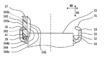
図9は、図4に対応する断面図である。コアプレート24は、先行する実施形態の側板33よりやや高い側板433を備える。側板433は、タンク部材27の縁部441を抱え込むことができるように設定されている。
FIG. 9 is a cross-sectional view corresponding to FIG. The
タンク部材27は、先行する実施形態の縁部41よりやや高い縁部441を有する。縁部441は、チューブ22との干渉を避けるように高く形成されている。タンク部材27は、波状外面443を有する。波状外面443は、外峰部443aと、外谷部443bとを有する。外谷部443bは、爪35を受け入れ可能である。外谷部443bは、段差部42を形成する。
The
タンク部材27は、波状内面444を有する。内峰部444aは、チューブ22の延長上において、2つのチューブ22の間に位置している。内峰部444aは、チューブ22より上にだけ位置するように形成されている。内峰部444aは、タンク部材27の開口端の端面に向けて近づくにつれて、外側へ推移する拡大部446を有する。この結果、幅方向WDに関してチューブ22と重複する位置には、縁部41だけが設けられている。この構成では、長さ方向LGに関して、すなわち図9の図示方向に関して、内峰部444aとチューブ22とは重複しない。
The
この実施形態では、長さ方向LGに沿ってチューブ22と内峰部444aとは重複することがない。しかし、この実施形態でも、チューブ22の延長上においては、隣接する2つのチューブ22の間に内峰部444aが位置付けられている。内峰部444aは、隣り合う2つのチューブ22の間に位置することがない。しかし、内峰部444aは、チューブ22の高さ方向HGの延長上において、2つのチューブ22の間に位置している。内谷部444bは、チューブ22の高さ方向HGの延長上において空間を提供している。これにより、タンク部材27の壁の厚さを必要な厚さに設定しながら、タンク部材27とチューブ22との干渉を確実に回避することができる。この結果、かしめ部のための段差部42を内側に設けることができる。
In this embodiment, the
(他の実施形態)
上記実施形態では、爪および波状壁のピッチは、チューブ22のピッチの1倍または2倍に設定した。これに代えて、3倍、4倍などを採用してもよい。タンク部材27とコアプレート24との連結の強固さを求める場合、爪および波状壁のピッチは、チューブ22のピッチP22の1倍または2倍が望ましい。
(Other embodiments)
In the above embodiment, the pitch between the claws and the wavy wall is set to be 1 or 2 times the pitch of the
また、上記実施形態では、複数の爪35と複数の段差部42とを同じ数だけ設けた。また、全体にわたって同じピッチを採用した。これに代えて、複数の爪35の数を部分的に、または全体にわたって減らしてもよい。例えば、第1実施形態の複数の爪35に代えて、1/2の数の爪35を設けてもよい。この場合、タンク部材27に設けられる段差部42の数は、爪35の数の2倍となる。また、複数のピッチを採用してもよい。例えば、コアプレート24および/またはタンク部材27上の一部範囲に第1ピッチで爪35および段差部42が設けられる。残る範囲には、第1ピッチと異なる第2ピッチで爪35および段差部42が設けられる。この場合においても、爪のピッチと、段差部のピッチとは、チューブ22のピッチP22の自然数倍に設定され、爪と段差部とは、隣接する2つのチューブ22の間に対応して配置される。
In the above embodiment, the same number of the plurality of
また、上記実施形態では、すべての爪35を曲げることによって多数のかしめ部を形成した。これに代えて、一部の爪35だけを曲げてもよい。この場合、一部の爪35は、曲げられていない真っ直ぐの形状である。例えば、チューブ22のピッチP22の2倍の位置にある爪35だけを曲げてもよい。また、内部流体の入口パイプおよび/または出口パイプの近傍においては、加工工程の容易化のために曲げられていない爪35を設けてもよい。
In the above embodiment, a large number of caulking portions are formed by bending all the
上記実施形態では、波状外面と波状内面とを滑らかに続く曲面によって形成した。これに代えて、波状外面と波状内面とを複数の平面によって構成してもよい。例えば、波状外面と波状内面とを台形波状または矩形波状に形成してもよい。 In the above embodiment, the undulating outer surface and the undulating inner surface are formed by a smoothly curved surface. Instead, the waved outer surface and the waved inner surface may be constituted by a plurality of planes. For example, the waved outer surface and the waved inner surface may be formed in a trapezoidal wave shape or a rectangular wave shape.
上記実施形態では、タンク部材27は樹脂製である。これに代えて、タンク部材27は、アルミ合金などの金属製としてもよい。
In the above embodiment, the
ここに開示される発明は、その発明を実施するための実施形態に何ら制限されることなく、種々変形して実施することが可能である。開示される発明は、実施形態において示された組み合わせに限定されることなく、種々の組み合わせによって実施可能である。実施形態は追加的な部分をもつことができる。実施形態の部分は、省略される場合がある。実施形態の部分は、他の実施形態の部分と置き換え、または組み合わせることも可能である。実施形態の構造、作用、効果は、あくまで例示である。開示される発明の技術的範囲は、実施形態の記載に限定されない。開示される発明のいくつかの技術的範囲は、特許請求の範囲の記載によって示され、さらに特許請求の範囲の記載と均等の意味及び範囲内での全ての変更を含むものと解されるべきである。 The invention disclosed herein is not limited to the embodiments for carrying out the invention, and can be implemented with various modifications. The disclosed invention is not limited to the combinations shown in the embodiments, and can be implemented in various combinations. Embodiments can have additional parts. The portion of the embodiment may be omitted. The parts of the embodiments can be replaced or combined with the parts of the other embodiments. The structure, operation, and effect of the embodiment are merely examples. The technical scope of the disclosed invention is not limited to the description of the embodiments. Some technical scope of the disclosed invention is indicated by the description of the claims, and should be understood to include all modifications within the meaning and scope equivalent to the description of the claims. It is.
10 熱交換器、 11 熱システム、 12 熱機器、
21 コア、 22 チューブ、 23 フィン、
24、25 コアプレート、 26 サイドプレート、
27、28 タンク部材、 29 ガスケット、
31 底板、 32 貫通孔、 33、433 側板、 34 シール面、
35、235 爪、 41、441 縁部、 42 段差部、
43、243、343、443 波状外面、
44、244、344、444 波状内面、
45、245、345、445 波状壁、
446 拡大部。
10 heat exchanger, 11 heat system, 12 heat equipment,
21 cores, 22 tubes, 23 fins,
24, 25 Core plate, 26 Side plate,
27, 28 Tank member, 29 Gasket,
31 bottom plate, 32 through hole, 33, 433 side plate, 34 sealing surface,
35, 235 nail, 41, 441 edge, 42 step,
43, 243, 343, 443 wavy outer surface,
44, 244, 344, 444 wavy inner surface,
45, 245, 345, 445 wavy walls,
446 Enlarged part.
Claims (7)
複数の前記チューブが接合されたコアプレート(24、25)と、
前記コアプレートに連結されたタンク部材(27、28)とを備え、前記コアプレートの縁と前記タンク部材の縁とがかしめ部によって連結されている熱交換器において、
前記かしめ部は、
前記コアプレートの縁に設けられた複数の爪(35、235)と、
前記タンク部材の開口端に設けられた縁部(441)と、
前記タンク部材に、長さ方向(LG)に沿って波状に設けられた波状壁(445)とを有し、
前記波状壁は、
前記縁部の上の外面に設けられ、交互に配置された複数の外峰部と複数の外谷部とを含む波状外面(443)と、
前記タンク部材の内面に設けられ、交互に配置された複数の内峰部と複数の内谷部とを含む波状内面(444)とを有し、
複数の前記外谷部(443b)は、前記爪を受け入れ可能であるとともに、前記爪が接触する段差部(42)を前記縁部の上に形成しており、
前記内峰部(444a)は、幅方向(WD)における前記外谷部の内側に位置しており、
前記内峰部は、隣り合う前記チューブの間および/または前記チューブの高さ方向(HG)の延長上における前記チューブの間に位置付けられており、
前記内峰部が規定する前記タンク部材の内幅(Wir)は、前記チューブの幅(W22)より小さく、
前記内峰部は、隣り合う前記チューブの間に位置することなく、前記チューブの前記高さ方向(HG)の延長上において前記チューブの間に位置しており、
前記内谷部(444b)は、前記チューブの前記高さ方向の延長上において空間を提供していることを特徴とする熱交換器。 A plurality of tubes (22);
A core plate (24, 25) to which a plurality of the tubes are joined;
A heat exchanger including tank members (27, 28) connected to the core plate, wherein an edge of the core plate and an edge of the tank member are connected by a caulking portion;
The caulking portion is
A plurality of claws (35, 235) provided on an edge of the core plate;
An edge ( 441 ) provided at the open end of the tank member;
The tank member has a wavy wall ( 445 ) provided in a wavy shape along the length direction (LG),
The wavy wall is
An undulating outer surface ( 443 ) provided on the outer surface above the edge and including a plurality of alternately arranged outer ridges and a plurality of outer valleys;
A corrugated inner surface ( 444 ) provided on the inner surface of the tank member and including a plurality of alternately arranged inner ridges and a plurality of inner valleys ;
A plurality of the outer valley portions ( 443b ) can receive the claw, and form a stepped portion (42) on which the claw contacts on the edge portion,
The inner ridge portion ( 444a ) is located inside the outer valley portion in the width direction (WD),
The inner ridges are positioned between the adjacent tubes and / or between the tubes on an extension in the height direction (HG) of the tubes;
The inner width (Wir) of the tank member defined by the inner ridge portion is smaller than the width (W22) of the tube,
The inner ridge portion is located between the tubes on the extension of the height direction (HG) of the tubes without being located between the adjacent tubes,
The inner valley portion ( 444b ) provides a space on the extension in the height direction of the tube.
前記爪は、前記側板の端に設けられており、
前記爪の前記長さ方向(LG)の寸法(L35、L235)は、隣り合う2つの前記チューブの間の間隔(G22)より小さいことを特徴とする請求項1から請求項3のいずれかに記載の熱交換器。 The core plate has a bottom plate (31) to which the tube is joined, and a side plate (33) rising from an edge of the bottom plate,
The claw is provided at an end of the side plate,
The dimensions of the length direction of the nail (LG) (L35, L235) from claim 1, wherein the smaller than the spacing between two of said tubes adjacent (G22) to any one of claims 3 The described heat exchanger.
前記コアプレートと前記タンク部材との前記幅方向(WD)に沿って延びる辺には、前記チューブのピッチに依存しない爪と段差部とを含むかしめ部が設けられていることを特徴とする請求項1から請求項6のいずれかに記載の熱交換器。 The claw and the wavy wall are provided only on sides extending along the length direction (LG) of the core plate and the tank member,
In the width direction (WD) sides extending along the said tank member and the core plate, wherein, wherein a caulking portion including the claw and the step portion which does not depend on the pitch of the tube is provided with The heat exchanger according to any one of claims 1 to 6 .
Priority Applications (4)
| Application Number | Priority Date | Filing Date | Title |
|---|---|---|---|
| JP2013225901A JP6337442B2 (en) | 2013-10-30 | 2013-10-30 | Heat exchanger |
| PCT/JP2014/005461 WO2015064093A1 (en) | 2013-10-30 | 2014-10-29 | Heat exchanger |
| EP14800153.0A EP3063490B1 (en) | 2013-10-30 | 2014-10-29 | Heat exchanger |
| US15/033,117 US10598444B2 (en) | 2013-10-30 | 2014-10-29 | Heat exchanger |
Applications Claiming Priority (1)
| Application Number | Priority Date | Filing Date | Title |
|---|---|---|---|
| JP2013225901A JP6337442B2 (en) | 2013-10-30 | 2013-10-30 | Heat exchanger |
Related Child Applications (1)
| Application Number | Title | Priority Date | Filing Date |
|---|---|---|---|
| JP2017223708A Division JP6508297B2 (en) | 2017-11-21 | 2017-11-21 | Heat exchanger |
Publications (3)
| Publication Number | Publication Date |
|---|---|
| JP2015087055A JP2015087055A (en) | 2015-05-07 |
| JP2015087055A5 JP2015087055A5 (en) | 2016-03-31 |
| JP6337442B2 true JP6337442B2 (en) | 2018-06-06 |
Family
ID=51932561
Family Applications (1)
| Application Number | Title | Priority Date | Filing Date |
|---|---|---|---|
| JP2013225901A Active JP6337442B2 (en) | 2013-10-30 | 2013-10-30 | Heat exchanger |
Country Status (4)
| Country | Link |
|---|---|
| US (1) | US10598444B2 (en) |
| EP (1) | EP3063490B1 (en) |
| JP (1) | JP6337442B2 (en) |
| WO (1) | WO2015064093A1 (en) |
Families Citing this family (5)
| Publication number | Priority date | Publication date | Assignee | Title |
|---|---|---|---|---|
| JP6394202B2 (en) * | 2013-11-27 | 2018-09-26 | 株式会社デンソー | Heat exchanger |
| WO2017069280A1 (en) | 2015-10-22 | 2017-04-27 | 株式会社ティラド | Heat exchanger and method for assembling same |
| JP6551293B2 (en) * | 2016-04-20 | 2019-07-31 | 株式会社デンソー | Heat exchanger |
| FR3062473B1 (en) * | 2017-01-31 | 2019-04-19 | Valeo Systemes Thermiques | COLLECTOR FOR HEAT EXCHANGER. |
| JP6992581B2 (en) * | 2018-02-20 | 2022-01-13 | 株式会社デンソー | Heat exchanger |
Family Cites Families (15)
| Publication number | Priority date | Publication date | Assignee | Title |
|---|---|---|---|---|
| DE2852408B2 (en) | 1978-12-04 | 1981-10-01 | Süddeutsche Kühlerfabrik Julius Fr. Behr GmbH & Co KG, 7000 Stuttgart | Clamp connection |
| FR2547403B1 (en) * | 1983-06-09 | 1985-07-19 | Chausson Usines Sa | HEAT EXCHANGER COMPRISING TUBES ENGAGED IN A COLLECTOR PLATE SET ON A WATER BOX |
| JPH01114697A (en) * | 1987-10-29 | 1989-05-08 | Nippon Denso Co Ltd | Heat exchanger |
| DE4330865A1 (en) | 1993-09-11 | 1995-03-16 | Behr Gmbh & Co | Heat exchanger, in particular radiator, for motor vehicles |
| FR2745079B1 (en) * | 1996-02-20 | 1998-04-10 | Valeo Thermique Moteur Sa | BRAZED FLUID BOX HEAT EXCHANGER, ESPECIALLY FOR MOTOR VEHICLES |
| JP3414171B2 (en) * | 1996-11-29 | 2003-06-09 | 株式会社デンソー | Heat exchanger |
| JP3797109B2 (en) * | 2001-01-19 | 2006-07-12 | 株式会社デンソー | Evaporator |
| PL1702191T3 (en) | 2003-12-19 | 2020-09-21 | Valeo, Inc. | Collar rib for heat exchanger tanks |
| JP2005221151A (en) * | 2004-02-05 | 2005-08-18 | Calsonic Kansei Corp | Heat exchanger and header tank |
| JP2005326124A (en) * | 2004-05-17 | 2005-11-24 | Calsonic Kansei Corp | Tube plate structure of heat exchanger |
| DE102004033784A1 (en) * | 2004-07-12 | 2006-02-02 | Behr Gmbh & Co. Kg | Heat exchangers, in particular intercoolers |
| FR2904101B1 (en) | 2006-07-21 | 2008-09-05 | Valeo Systemes Thermiques | HEAT EXCHANGER WITH IMPROVED COLLECTOR |
| FR2927412B1 (en) | 2008-02-13 | 2012-12-21 | Valeo Systemes Thermiques | COLLECTOR PLATE WITHOUT THROAT |
| JP2011144973A (en) * | 2010-01-13 | 2011-07-28 | Denso Corp | Heat exchanger |
| DE102011008220A1 (en) | 2010-01-13 | 2012-01-19 | Denso Corporation | heat exchangers |
-
2013
- 2013-10-30 JP JP2013225901A patent/JP6337442B2/en active Active
-
2014
- 2014-10-29 EP EP14800153.0A patent/EP3063490B1/en active Active
- 2014-10-29 US US15/033,117 patent/US10598444B2/en not_active Expired - Fee Related
- 2014-10-29 WO PCT/JP2014/005461 patent/WO2015064093A1/en active Application Filing
Also Published As
| Publication number | Publication date |
|---|---|
| US10598444B2 (en) | 2020-03-24 |
| JP2015087055A (en) | 2015-05-07 |
| US20160258693A1 (en) | 2016-09-08 |
| WO2015064093A1 (en) | 2015-05-07 |
| EP3063490A1 (en) | 2016-09-07 |
| EP3063490B1 (en) | 2020-05-13 |
Similar Documents
| Publication | Publication Date | Title |
|---|---|---|
| JP6337442B2 (en) | Heat exchanger | |
| JP5856068B2 (en) | Heat exchanger | |
| US8910704B2 (en) | Heat exchanger | |
| EP1722184A2 (en) | Coupling structure of heat transfer plate and gasket of plate type heat exchanger | |
| US20120118548A1 (en) | Plate Heat Exchanger | |
| JP5952259B2 (en) | Heat exchanger | |
| JP5476585B2 (en) | Cooler | |
| EP2458312B1 (en) | Heat exchanger for an internal combustion engine | |
| JP6938669B2 (en) | Heat exchanger for automatic vehicles | |
| US6662859B2 (en) | Cooler for power electronics | |
| US10837707B2 (en) | Heat exchanger | |
| JP2009146948A (en) | Fin for heat exchanger, and manufacturing method therefor | |
| US20180094870A1 (en) | Heat exchanger | |
| JP2018028431A (en) | Heat exchanger | |
| US20210123690A1 (en) | Heat Exchange Tube, Heat Exchange Tube Manufacturing Method, and Heat Exchanger | |
| US10281222B2 (en) | Heat exchanger | |
| CN112146484B (en) | Plate heat exchanger | |
| CN110118504B (en) | Flat tube | |
| JP6764765B2 (en) | Heat transfer member | |
| JPWO2019163973A1 (en) | Heat exchanger tank structure | |
| JP4341490B2 (en) | Heat exchanger | |
| JP2019190674A (en) | Heat exchanger | |
| CN211900771U (en) | High-performance radiator for engine | |
| CN211178077U (en) | Ohm type special-shaped seal radiator | |
| JP2007170747A (en) | Heat exchanger |
Legal Events
| Date | Code | Title | Description |
|---|---|---|---|
| A521 | Request for written amendment filed |
Free format text: JAPANESE INTERMEDIATE CODE: A523 Effective date: 20160216 |
|
| A621 | Written request for application examination |
Free format text: JAPANESE INTERMEDIATE CODE: A621 Effective date: 20160913 |
|
| A131 | Notification of reasons for refusal |
Free format text: JAPANESE INTERMEDIATE CODE: A131 Effective date: 20170822 |
|
| A521 | Request for written amendment filed |
Free format text: JAPANESE INTERMEDIATE CODE: A523 Effective date: 20171121 |
|
| TRDD | Decision of grant or rejection written | ||
| A01 | Written decision to grant a patent or to grant a registration (utility model) |
Free format text: JAPANESE INTERMEDIATE CODE: A01 Effective date: 20180410 |
|
| A61 | First payment of annual fees (during grant procedure) |
Free format text: JAPANESE INTERMEDIATE CODE: A61 Effective date: 20180423 |
|
| R150 | Certificate of patent or registration of utility model |
Ref document number: 6337442 Country of ref document: JP Free format text: JAPANESE INTERMEDIATE CODE: R150 |
|
| R250 | Receipt of annual fees |
Free format text: JAPANESE INTERMEDIATE CODE: R250 |
|
| R250 | Receipt of annual fees |
Free format text: JAPANESE INTERMEDIATE CODE: R250 |
|
| R250 | Receipt of annual fees |
Free format text: JAPANESE INTERMEDIATE CODE: R250 |