JP6394202B2 - Heat exchanger - Google Patents
Heat exchanger Download PDFInfo
- Publication number
- JP6394202B2 JP6394202B2 JP2014179461A JP2014179461A JP6394202B2 JP 6394202 B2 JP6394202 B2 JP 6394202B2 JP 2014179461 A JP2014179461 A JP 2014179461A JP 2014179461 A JP2014179461 A JP 2014179461A JP 6394202 B2 JP6394202 B2 JP 6394202B2
- Authority
- JP
- Japan
- Prior art keywords
- tube
- core plate
- tubes
- heat exchanger
- longitudinal direction
- Prior art date
- Legal status (The legal status is an assumption and is not a legal conclusion. Google has not performed a legal analysis and makes no representation as to the accuracy of the status listed.)
- Active
Links
Images


Classifications
-
- F—MECHANICAL ENGINEERING; LIGHTING; HEATING; WEAPONS; BLASTING
- F28—HEAT EXCHANGE IN GENERAL
- F28F—DETAILS OF HEAT-EXCHANGE AND HEAT-TRANSFER APPARATUS, OF GENERAL APPLICATION
- F28F9/00—Casings; Header boxes; Auxiliary supports for elements; Auxiliary members within casings
- F28F9/02—Header boxes; End plates
- F28F9/0219—Arrangements for sealing end plates into casing or header box; Header box sub-elements
- F28F9/0224—Header boxes formed by sealing end plates into covers
- F28F9/0226—Header boxes formed by sealing end plates into covers with resilient gaskets
-
- F—MECHANICAL ENGINEERING; LIGHTING; HEATING; WEAPONS; BLASTING
- F28—HEAT EXCHANGE IN GENERAL
- F28D—HEAT-EXCHANGE APPARATUS, NOT PROVIDED FOR IN ANOTHER SUBCLASS, IN WHICH THE HEAT-EXCHANGE MEDIA DO NOT COME INTO DIRECT CONTACT
- F28D1/00—Heat-exchange apparatus having stationary conduit assemblies for one heat-exchange medium only, the media being in contact with different sides of the conduit wall, in which the other heat-exchange medium is a large body of fluid, e.g. domestic or motor car radiators
- F28D1/02—Heat-exchange apparatus having stationary conduit assemblies for one heat-exchange medium only, the media being in contact with different sides of the conduit wall, in which the other heat-exchange medium is a large body of fluid, e.g. domestic or motor car radiators with heat-exchange conduits immersed in the body of fluid
- F28D1/04—Heat-exchange apparatus having stationary conduit assemblies for one heat-exchange medium only, the media being in contact with different sides of the conduit wall, in which the other heat-exchange medium is a large body of fluid, e.g. domestic or motor car radiators with heat-exchange conduits immersed in the body of fluid with tubular conduits
- F28D1/053—Heat-exchange apparatus having stationary conduit assemblies for one heat-exchange medium only, the media being in contact with different sides of the conduit wall, in which the other heat-exchange medium is a large body of fluid, e.g. domestic or motor car radiators with heat-exchange conduits immersed in the body of fluid with tubular conduits the conduits being straight
- F28D1/0535—Heat-exchange apparatus having stationary conduit assemblies for one heat-exchange medium only, the media being in contact with different sides of the conduit wall, in which the other heat-exchange medium is a large body of fluid, e.g. domestic or motor car radiators with heat-exchange conduits immersed in the body of fluid with tubular conduits the conduits being straight the conduits having a non-circular cross-section
- F28D1/05366—Assemblies of conduits connected to common headers, e.g. core type radiators
- F28D1/05383—Assemblies of conduits connected to common headers, e.g. core type radiators with multiple rows of conduits or with multi-channel conduits
-
- F—MECHANICAL ENGINEERING; LIGHTING; HEATING; WEAPONS; BLASTING
- F28—HEAT EXCHANGE IN GENERAL
- F28F—DETAILS OF HEAT-EXCHANGE AND HEAT-TRANSFER APPARATUS, OF GENERAL APPLICATION
- F28F9/00—Casings; Header boxes; Auxiliary supports for elements; Auxiliary members within casings
- F28F9/02—Header boxes; End plates
- F28F9/04—Arrangements for sealing elements into header boxes or end plates
- F28F9/16—Arrangements for sealing elements into header boxes or end plates by permanent joints, e.g. by rolling
- F28F9/18—Arrangements for sealing elements into header boxes or end plates by permanent joints, e.g. by rolling by welding
- F28F9/182—Arrangements for sealing elements into header boxes or end plates by permanent joints, e.g. by rolling by welding the heat-exchange conduits having ends with a particular shape, e.g. deformed; the heat-exchange conduits or end plates having supplementary joining means, e.g. abutments
-
- F—MECHANICAL ENGINEERING; LIGHTING; HEATING; WEAPONS; BLASTING
- F28—HEAT EXCHANGE IN GENERAL
- F28D—HEAT-EXCHANGE APPARATUS, NOT PROVIDED FOR IN ANOTHER SUBCLASS, IN WHICH THE HEAT-EXCHANGE MEDIA DO NOT COME INTO DIRECT CONTACT
- F28D1/00—Heat-exchange apparatus having stationary conduit assemblies for one heat-exchange medium only, the media being in contact with different sides of the conduit wall, in which the other heat-exchange medium is a large body of fluid, e.g. domestic or motor car radiators
- F28D1/02—Heat-exchange apparatus having stationary conduit assemblies for one heat-exchange medium only, the media being in contact with different sides of the conduit wall, in which the other heat-exchange medium is a large body of fluid, e.g. domestic or motor car radiators with heat-exchange conduits immersed in the body of fluid
- F28D1/04—Heat-exchange apparatus having stationary conduit assemblies for one heat-exchange medium only, the media being in contact with different sides of the conduit wall, in which the other heat-exchange medium is a large body of fluid, e.g. domestic or motor car radiators with heat-exchange conduits immersed in the body of fluid with tubular conduits
- F28D1/053—Heat-exchange apparatus having stationary conduit assemblies for one heat-exchange medium only, the media being in contact with different sides of the conduit wall, in which the other heat-exchange medium is a large body of fluid, e.g. domestic or motor car radiators with heat-exchange conduits immersed in the body of fluid with tubular conduits the conduits being straight
- F28D1/0535—Heat-exchange apparatus having stationary conduit assemblies for one heat-exchange medium only, the media being in contact with different sides of the conduit wall, in which the other heat-exchange medium is a large body of fluid, e.g. domestic or motor car radiators with heat-exchange conduits immersed in the body of fluid with tubular conduits the conduits being straight the conduits having a non-circular cross-section
- F28D1/05366—Assemblies of conduits connected to common headers, e.g. core type radiators
-
- F—MECHANICAL ENGINEERING; LIGHTING; HEATING; WEAPONS; BLASTING
- F28—HEAT EXCHANGE IN GENERAL
- F28F—DETAILS OF HEAT-EXCHANGE AND HEAT-TRANSFER APPARATUS, OF GENERAL APPLICATION
- F28F2225/00—Reinforcing means
- F28F2225/08—Reinforcing means for header boxes
-
- F—MECHANICAL ENGINEERING; LIGHTING; HEATING; WEAPONS; BLASTING
- F28—HEAT EXCHANGE IN GENERAL
- F28F—DETAILS OF HEAT-EXCHANGE AND HEAT-TRANSFER APPARATUS, OF GENERAL APPLICATION
- F28F2275/00—Fastening; Joining
- F28F2275/12—Fastening; Joining by methods involving deformation of the elements
- F28F2275/122—Fastening; Joining by methods involving deformation of the elements by crimping, caulking or clinching
-
- F—MECHANICAL ENGINEERING; LIGHTING; HEATING; WEAPONS; BLASTING
- F28—HEAT EXCHANGE IN GENERAL
- F28F—DETAILS OF HEAT-EXCHANGE AND HEAT-TRANSFER APPARATUS, OF GENERAL APPLICATION
- F28F2280/00—Mounting arrangements; Arrangements for facilitating assembling or disassembling of heat exchanger parts
- F28F2280/04—Means for preventing wrong assembling of parts
Landscapes
- Engineering & Computer Science (AREA)
- Physics & Mathematics (AREA)
- Thermal Sciences (AREA)
- Mechanical Engineering (AREA)
- General Engineering & Computer Science (AREA)
- Heat-Exchange Devices With Radiators And Conduit Assemblies (AREA)
- Air-Conditioning For Vehicles (AREA)
Description
本発明は、熱交換器に関するもので、車両に搭載される車両用の熱交換器に適用して有効である。 The present invention relates to a heat exchanger, and is effective when applied to a vehicle heat exchanger mounted on a vehicle.
従来、ラジエータ等の熱交換器のヘッダタンクは、各チューブが接合された金属製のコアプレートと、タンク内空間を形成する樹脂製のタンク本体部とを一体化することによって構成されている。コアプレートとタンク本体部との間には、ゴム等の弾性部材からなるパッキン(シール部材)が配置されており、このパッキンをコアプレートおよびタンク本体部にて圧縮することで、コアプレートとタンク本体部とをシールしている。 2. Description of the Related Art Conventionally, a header tank of a heat exchanger such as a radiator is configured by integrating a metal core plate to which tubes are joined and a resin tank main body forming a tank internal space. A packing (seal member) made of an elastic member such as rubber is disposed between the core plate and the tank main body. The core plate and the tank are compressed by compressing the packing between the core plate and the tank main body. The main body is sealed.
具体的には、コアプレートは、チューブが接合されるチューブ接合面と、チューブ接合面の外周縁部に形成された溝部とを有している。そして、コアプレートの溝部には、タンク本体部のうちコアプレート側の先端部が挿入されており、コアプレートの溝部とタンク本体部の先端部との間にパッキンが挟まれた状態で、タンク本体部がコアプレートにカシメ固定されている。 Specifically, the core plate has a tube joint surface to which the tube is joined, and a groove formed at the outer peripheral edge of the tube joint surface. The core plate side tip portion of the tank main body portion is inserted into the core plate groove portion, and the tank is sandwiched between the core plate groove portion and the tank main body tip portion. The main body is caulked and fixed to the core plate.
このような構成の熱交換器では、コアプレートに溝部を形成しているので、この溝部の分だけ、コアプレートにおける外部流体(空気)の流れ方向の長さ(以下、幅方向寸法ともいう)が長くなる。これにより、熱交換器全体としての幅方向寸法が長くなるという問題があった。 In the heat exchanger having such a configuration, since the groove portion is formed in the core plate, the length in the flow direction of the external fluid (air) in the core plate by the amount of the groove portion (hereinafter also referred to as the width direction dimension). Becomes longer. Thereby, there existed a problem that the width direction dimension as the whole heat exchanger became long.
これに対し、コアプレートの溝部を廃止することで薄幅化を図った熱交換器が開示されている(例えば、特許文献1参照)。具体的には、特許文献1に記載の熱交換器では、コアプレートにおけるチューブが挿入接合されるチューブ接合面上に直接パッキンが配置されているとともに、このパッキン上にタンク本体部の端部が配置されている。そして、コアプレートのチューブ接合面とタンク本体部の先端部との間にパッキンが挟まれた状態で、タンク本体部がコアプレートにカシメ固定されている。 On the other hand, the heat exchanger which aimed at thickness reduction by eliminating the groove part of a core plate is disclosed (for example, refer patent document 1). Specifically, in the heat exchanger described in Patent Document 1, a packing is directly disposed on a tube joining surface to which a tube in a core plate is inserted and joined, and an end of a tank main body is disposed on the packing. Has been placed. The tank body is caulked and fixed to the core plate in a state where the packing is sandwiched between the tube joint surface of the core plate and the tip of the tank body.
しかしながら、上記特許文献1に記載の熱交換器では、パッキンが、コアプレートのチューブ接合面上に直接配置されるため、コアプレートとタンク本体部とのカシメ固定時にパッキンの位置ズレが発生するおそれがある。 However, in the heat exchanger described in Patent Document 1, since the packing is directly disposed on the tube joint surface of the core plate, there is a risk that the packing may be misaligned when the core plate and the tank main body are fixed by caulking. There is.
本発明は上記点に鑑みて、シール部材の位置ズレを抑制しつつ、幅方向寸法を小さくすることができる熱交換器を提供することを目的とする。 An object of this invention is to provide the heat exchanger which can make the width direction dimension small, suppressing the position shift of a sealing member in view of the said point.
上記目的を達成するため、本発明では、互いに並設配置されるとともに、内部に流体が流通する複数のチューブ(2)と、チューブ(2)の長手方向端部に配置されるとともに、複数のチューブ(2)の並設方向に延びて複数のチューブ(2)に連通するヘッダタンク(5)とを備え、ヘッダタンク(5)は、複数のチューブ(2)が接合されるコアプレート(51)と、コアプレート(51)に固定されるタンク本体部(52)とを有している熱交換器において、コアプレート(51)は、チューブ(2)が挿入接合されるチューブ接合面(511)と、弾性変形可能なシール部材(53)が配置されるシール面(512)とを有しており、チューブ接合面(511)とシール面(512)とは、チューブ(2)の長手方向の端面(20)からのチューブ(2)の長手方向の距離が、互いに異なっており、チューブ接合面(511)とシール面(512)とは、チューブ(2)の長手方向に対して傾斜した傾斜面(513)を介して連続して接続されており、チューブ(2)は、チューブ接合面(511)と、傾斜面(513)の少なくとも一部とに挿入接合されており、コアプレート(51)の傾斜面(513)における隣り合うチューブ(2)同士の間と対応する部位には、リブ(518)が設けられており、リブ(518)は、チューブの長手方向に平行な平面部(517)を有していることを特徴としている。 In order to achieve the above object, in the present invention, a plurality of tubes (2) that are arranged in parallel with each other, and that are arranged at the longitudinal ends of the tubes (2), and that a plurality of A header tank (5) that extends in the juxtaposition direction of the tubes (2) and communicates with the plurality of tubes (2). The header tank (5) includes a core plate (51) to which the plurality of tubes (2) are joined. ) And a tank body (52) fixed to the core plate (51), the core plate (51) has a tube joining surface (511) into which the tube (2) is inserted and joined. ) And a seal surface (512) on which the elastically deformable seal member (53) is disposed, and the tube joint surface (511) and the seal surface (512) are in the longitudinal direction of the tube (2). End face (20) The distances in the longitudinal direction of the tubes (2) are different from each other, and the tube joining surface (511) and the seal surface (512) are inclined surfaces (513) inclined with respect to the longitudinal direction of the tube (2). The tube (2) is inserted and joined to the tube joining surface (511) and at least a part of the inclined surface (513), and the inclined surface of the core plate (51) is connected. A rib (518) is provided at a portion corresponding to between adjacent tubes (2) in (513), and the rib (518) has a flat portion (517) parallel to the longitudinal direction of the tube. It is characterized by that.
これによれば、コアプレート(51)に、チューブ(2)が挿入接合されるチューブ接合面(511)と、弾性変形可能なシール部材(53)が配置されるシール面(512)とを設け、チューブ接合面(511)とシール面(512)とを、チューブ(2)の長手方向の端面(20)からのチューブ(2)の長手方向の距離を互いに異ならせることで、シール部材(53)の位置ズレを抑制できる。 According to this, the core plate (51) is provided with the tube joint surface (511) on which the tube (2) is inserted and joined, and the seal surface (512) on which the elastically deformable seal member (53) is arranged. The tube joining surface (511) and the sealing surface (512) are made different from each other in the longitudinal distance of the tube (2) from the longitudinal end surface (20) of the tube (2). ) Can be suppressed.
また、チューブ(2)を、チューブ接合面(511)と、傾斜面(513)の少なくとも一部とに挿入接合することで、チューブ接合面(511)の幅方向寸法が小さくすることができる。このため、ヘッダタンク(5)の幅方向寸法を小さくすることができる。したがって、シール部材(53)の位置ズレを抑制しつつ、熱交換器の幅方向寸法を小さくすることが可能となる。 Moreover, the width direction dimension of a tube joint surface (511) can be made small by inserting and joining a tube (2) to at least one part of a tube joint surface (511) and an inclined surface (513). For this reason, the width direction dimension of a header tank (5) can be made small. Therefore, it is possible to reduce the size in the width direction of the heat exchanger while suppressing displacement of the seal member (53).
なお、この欄および特許請求の範囲で記載した各手段の括弧内の符号は、後述する実施形態に記載の具体的手段との対応関係を示すものである。 In addition, the code | symbol in the bracket | parenthesis of each means described in this column and the claim shows the correspondence with the specific means as described in embodiment mentioned later.
以下、本発明の実施形態について図に基づいて説明する。なお、以下の各実施形態相互において、互いに同一もしくは均等である部分には、図中、同一符号を付してある。 Hereinafter, embodiments of the present invention will be described with reference to the drawings. In the following embodiments, the same or equivalent parts are denoted by the same reference numerals in the drawings.
(第1実施形態)
本発明の第1実施形態について図面に基づいて説明する。本実施形態では、本発明に係る熱交換器を、エンジン冷却水と空気との間で熱交換を行いエンジン冷却水を冷却する自動車用ラジエータに適用した場合を例として説明する。
(First embodiment)
A first embodiment of the present invention will be described with reference to the drawings. In the present embodiment, a case where the heat exchanger according to the present invention is applied to an automotive radiator that cools engine cooling water by exchanging heat between engine cooling water and air will be described as an example.
図1に示すように、本実施形態のラジエータ1は、複数のチューブ2およびフィン3からなるコア部4と、コア部4の両端部に組み付け配置される一対のヘッダタンク5とを有している。
As shown in FIG. 1, the radiator 1 of the present embodiment includes a core portion 4 composed of a plurality of
チューブ2は流体(本実施形態ではエンジン冷却水)が流れる管である。このチューブ2は、空気流れ方向が長径方向と一致するように扁平状に形成されているとともに、その長手方向が水平方向に一致するように垂直方向に複数本平行に配置されている。
The
フィン3は、波状に成形されるとともに、チューブ2の両側の扁平面に接合されている。このフィン3により、空気との伝熱面積を増大させてチューブ2内を流通するエンジン冷却水と空気との熱交換を促進している。
The fins 3 are formed in a wave shape and are joined to flat surfaces on both sides of the
ヘッダタンク5は、チューブ2の長手方向(以下、チューブ長手方向という)の両端部にてチューブ長手方向と直交する方向に延びて複数のチューブ2と連通するものである。本実施形態では、ヘッダタンク5は、チューブ2の左右端に配置されており、鉛直方向に延びて複数のチューブ2と連通している。このヘッダタンク5は、チューブ2が挿入接合されるコアプレート51と、コアプレート51とともにタンク空間を構成するタンク本体部52とを有して構成されている。
The
また、コア部4おけるチューブ2の積層方向(以下、チューブ積層方向という)の両端部には、コア部4を補強するサイドプレート6が設けられている。サイドプレート6は、チューブ長手方向と平行に延びてその両端部がヘッダタンク5に接続されている。
Further, side plates 6 that reinforce the core portion 4 are provided at both ends of the core portion 4 in the stacking direction of the tubes 2 (hereinafter referred to as tube stacking direction). The side plate 6 extends in parallel with the tube longitudinal direction, and both end portions thereof are connected to the
以下、ラジエータ1において、チューブ長手方向およびチューブ積層方向の双方に直交する方向を幅方向という。幅方向は、空気流れ方向と平行になっている。 Hereinafter, in the radiator 1, a direction orthogonal to both the tube longitudinal direction and the tube stacking direction is referred to as a width direction. The width direction is parallel to the air flow direction.
次に、ヘッダタンク5の詳細な構成を、図2〜図6に基づいて説明する。なお、図2では、後述するパッキン53の図示を省略している。
Next, the detailed structure of the
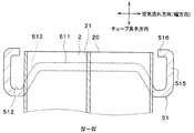
図2に示すように、ヘッダタンク5は、チューブ2およびサイドプレート6が挿入接合されるコアプレート51、コアプレート51と共にヘッダタンク5内の空間であるタンク内空間を構成するタンク本体部52、およびコアプレート51とタンク本体部52との間をシールするシール部材としてのパッキン53(後述する図6参照)を有している。本実施形態では、コアプレート51をアルミニウム合金製とし、タンク本体部52をガラス繊維で強化されたガラス強化ポリアミド等の樹脂製としている。
As shown in FIG. 2, the
そして、パッキン53をコアプレート51とタンク本体部52との間に挟んだ状態で、コアプレート51の後述するカシメ用爪部516をタンク本体部52に押し付けるように塑性変形させてタンク本体部52をコアプレート51にカシメ固定している。ここで、本実施形態のパッキン53は、弾性変形可能なゴム(本例では、エチレン−プロピレン−ジエンゴム(EPDM))により構成されている。
Then, in a state where the packing 53 is sandwiched between the
図3、図4および図5に示すように、コアプレート51は、チューブ2が挿入接合されるチューブ接合面511と、パッキン53が配置されるシール面512とを有している。本実施形態では、チューブ接合面511およびシール面512は、互いに平行になっている。具体的には、チューブ接合面511およびシール面512は、チューブ長手方向に対して垂直になっている。
As shown in FIGS. 3, 4, and 5, the
チューブ接合面511とシール面512とは、チューブ2のチューブ長手方向の端面(以下、チューブ端面20ともいう)からのチューブ長手方向の距離が、互いに異なっている。本実施形態では、チューブ接合面511からチューブ端面20までのチューブ長手方向の距離が、シール面512からチューブ端面20までのチューブ長手方向の距離よりも短くなっている。すなわち、シール面512は、チューブ接合面511よりも、チューブ2の長手方向の内側(コア部4に近い側)に配置されている。
The
チューブ接合面511とシール面512とは、チューブ長手方向に対して傾斜した傾斜面513を介して接続されている。本実施形態では、傾斜面513は、チューブ接合面511およびシール面512のそれぞれに対して傾斜している。具体的には、シール面512と傾斜面513との成す角、および、チューブ接合面511と傾斜面513との成す角は、それぞれ鈍角になっている。
The tube
チューブ接合面511および傾斜面513には、チューブ2が挿入されてろう付けされるチューブ挿入穴(図示せず)がチューブ積層方向に沿って多数形成されている。そして、チューブ2は、チューブ接合面511および傾斜面513に挿入接合されている。
A large number of tube insertion holes (not shown) into which the
また、チューブ接合面511および傾斜面513には、サイドプレート6が挿入されてろう付けされるサイドプレート挿入穴(図示せず)が、チューブ接合面511および傾斜面513のそれぞれにおけるチューブ積層方向の両端側に1つずつ形成されている。そして、サイドプレート6は、チューブ接合面511および傾斜面513に挿入接合されている。
In addition, side plate insertion holes (not shown) into which the side plate 6 is inserted and brazed are formed in the
コアプレート51は、シール面512からコア部4と反対側に向かって略直角に折り曲げられてチューブ積層方向または空気流れ方向に延びる外側壁部515を有している。
The
コアプレート51の傾斜面513における隣り合うチューブ2同士の間には、チューブ長手方向に平行な面(以下、平行面517という)を有するリブ518が設けられている。本実施形態では、平行面517は、空気流れ方向に対して垂直になっている。また、平行面517とシール面512との成す角度が略直角になっている。また、リブ518は、ヘッダタンク5の外方に突出するように形成されている。
Between the
図2に戻り、タンク本体部52の空気流れ方向の長さは、チューブ2の空気流れ方向の長さよりも短くなっている。タンク本体部52におけるチューブ2と対向する部位には、タンク外方側に向けて膨らんだ膨出部521が形成されている。これにより、タンク本体部52の内面とチューブ2の外面とが接触しないように構成されている。
Returning to FIG. 2, the length of the
タンク本体部52における隣り合うチューブ2同士の間に対向する部位、すなわち膨出部521が形成されていない部位には、コアプレート51側の端部が他の部位よりも板厚が厚くなっているフランジ部522が設けられている。フランジ部522は、コアプレート51のシール面512にパッキン53を介して配置されている。
In the portion of the tank
ところで、コアプレート51には、カシメ用爪部516が複数設けられている。カシメ用爪部516は、外側壁部515タンク本体部52側に突出するように形成されている。また、カシメ用爪部516は、コアプレート51における隣り合うチューブ2同士の間に対応する部位、すなわちタンク本体部52のフランジ部522に対応する部位に配置されている。そして、図6に示すように、カシメ用爪部516をタンク本体部52のフランジ部522にカシメ固定することによって、タンク本体部52はコアプレート51に組み付けられている。
Incidentally, the
なお、図2および図3に示すように、チューブ2の内部には、二つの扁平面同士を接続するように形成され、チューブ2の耐圧強度を高める内柱部21が設けられている。本実施形態では、内柱部21は、チューブ2内部における空気流れ方向の中央部に配置されている。この内柱部21により、チューブ2内部の流体通路が二つに仕切られている。
As shown in FIGS. 2 and 3, an
以上説明したように、本実施形態では、コアプレート51にチューブ接合面511とシール面512とを設け、チューブ接合面511とシール面512とを、チューブ端面20からのチューブ長手方向の距離を互いに異ならせている。すなわち、本実施形態では、コアプレート51において、チューブ2が挿入接合される面(チューブ接合面511)と、パッキン53が配置される面(シール面512)とが同一平面上に配置されていない。また、コアプレート51とタンク本体部52とのカシメ固定時には、ヘッダタンク5がコアプレート傾斜面513に当接し、保持されるため、チューブ2への干渉を防止することができる。
As described above, in the present embodiment, the
また、コアプレート51とタンク本体部52とのカシメ固定時にパッキン53は傾斜面513と当接するため、パッキン53の位置ズレを抑制できる。具体的には、シール面512を、傾斜面513と外側壁部515との間に形成することで、パッキン53の位置ズレをより確実に抑制できる。
Moreover, since the packing 53 contacts the
また、本実施形態では、チューブ2を、チューブ接合面511だけでなく、傾斜面513にも挿入接合している。これにより、チューブ接合面511の幅方向寸法が小さくなり、ヘッダタンク5の幅方向寸法を小さくすることができる。その結果、ラジエータ1の幅方向寸法を小さくすることが可能となる。
In this embodiment, the
ところで、上記特許文献1に記載の熱交換器では、コアプレート51のチューブ接合面511上にタンク本体部52のフランジ部522が配置されている。このため、ヘッダタンク5の製造工程において、タンク本体部52をコアプレート51上に配置する際に、フランジ部522がチューブ2に当接し、チューブ2が損傷するおそれがある。また、タンク本体部52とコアプレート51とをカシメ固定する際に、タンク本体部52がタンク内方側に向かって変形することで、チューブ2が損傷するおそれもある。
Incidentally, in the heat exchanger described in Patent Document 1, the
これに対し、本実施形態では、コアプレート51の傾斜面513における隣り合うチューブ2同士の間と対応する部位に、チューブ長手方向に平行な平行面517を有するリブ518を設けている。これにより、タンク本体部52をコアプレート51に組み付けた際に、タンク本体部52のフランジ部522が、コアプレート51におけるリブ518の平行面517と当接する。このため、フランジ部522がチューブ2に当接することを抑制できる。
On the other hand, in the present embodiment,
また、本実施形態では、タンク本体部52のフランジ部522が、コアプレート51におけるリブ518の平行面517と当接した状態で、タンク本体部52とコアプレート51とがカシメ固定される。このため、当該カシメ固定時に、タンク本体部52がタンク内方側に向かって変形することを抑制できる。
In the present embodiment, the
したがって、本実施形態のラジエータ1では、チューブ2が損傷することを確実に抑制することが可能となる。
Therefore, in the radiator 1 of this embodiment, it becomes possible to suppress reliably that the
また、コアプレート51の傾斜面513における隣り合うチューブ2同士の間と対応する部位に、チューブ長手方向に平行な平行面517を有するリブ518を設けることで、当該平行面517にタンク本体部52のフランジ部522が当接することになる。このため、コアプレート51にフランジ部522を配置する際、および、タンク本体部52とコアプレート51とをカシメ固定する際に、タンク本体部52を確実に保持することが可能となる。
Further, by providing
(第2実施形態)
次に、本発明の第2実施形態について図面に基づいて説明する。本第2実施形態は、上記第1実施形態と比較して、コアプレート51のチューブ挿入穴近傍の構成が異なるものである。
(Second Embodiment)
Next, 2nd Embodiment of this invention is described based on drawing. The second embodiment is different from the first embodiment in the configuration near the tube insertion hole of the
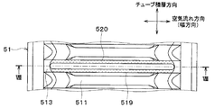
図7に示すように、コアプレート51のチューブ接合面511および傾斜面513の一部には、チューブ2が挿入されてろう付けされるチューブ挿入穴519がチューブ積層方向に沿って多数形成されている。
As shown in FIG. 7, a plurality of tube insertion holes 519 into which the
図7および図8に示すように、チューブ挿入穴519の縁部には、チューブ長手方向の端面20(図11参照)側に向けて突出するバーリング部520が設けられている。バーリング部520は、コアプレート51におけるチューブ接合面511および傾斜面513の双方に接続されている。なお、バーリング部520は、チューブ挿入穴519の縁部にバーリング加工を施すことにより形成されている。
As shown in FIGS. 7 and 8, a burring
以下、バーリング部520のうち、チューブ接合面511に接続される、すなわちチューブ接合面511と対向する部位を、第1バーリング部520aという。また、バーリング部520のうち、傾斜面513に接続される、すなわち傾斜面513と対向する部位を、第2バーリング部520bという。第1バーリング部520aおよび第2バーリング部520bは、一体に形成されている。
Hereinafter, a portion of the burring
図9に示すように、チューブ接合面511において、第1バーリング部520aのバーリング成形方向(図9中の矢印A参照)は、チューブ接合面511に対して垂直になっている。また、傾斜面513において、第2バーリング部520bのバーリング成形方向(図9中の矢印B参照)は、傾斜面513に対して鋭角になっている。このため、第2バーリング部520bにおけるチューブ長手方向の長さLbは、第1バーリング部520aにおけるチューブ長手方向の長さLaよりも長い。
As shown in FIG. 9, the burring forming direction (see arrow A in FIG. 9) of the
以上説明したように、本実施形態では、チューブ挿入穴519の縁部に、チューブ長手方向の端面20側に向けて突出するバーリング部520を設けている。これによれば、コアプレート51とチューブ2との根付部(接合部)の強度を向上させることができるので、耐熱歪み性(熱歪みに対する耐性)を向上させることが可能となる。
As described above, in the present embodiment, the burring
ところで、図11に示すように、コアプレート51とチューブ2との根付部のうち、傾斜面513とチューブ2の幅方向(空気流れ方向)の外側端部22との根付部Cに、最も大きい熱歪みが発生する。以下、当該根付部Cを、最大熱歪み発生部Cともいう。
By the way, as shown in FIG. 11, among the root portions of the
これに対し、本実施形態では、傾斜面513に接続されている第2バーリング部520bにおけるチューブ長手方向の長さLbを、チューブ接合面511に接続されている第1バーリング部520aにおけるチューブ長手方向の長さLaよりも長くしている。これによれば、最大熱歪み発生部Cに対応する第2バーリング部520bのチューブ長手方向の長さを長くしているので、最大熱歪み発生部Cの耐熱歪み性を確実に向上させることが可能となる。
In contrast, in the present embodiment, the length Lb in the tube longitudinal direction of the
(第3実施形態)
次に、本発明の第3実施形態について図面に基づいて説明する。本第3実施形態は、上記第1実施形態と比較して、コアプレート51およびタンク本体部52の構成が異なるものである。
(Third embodiment)
Next, 3rd Embodiment of this invention is described based on drawing. The third embodiment is different from the first embodiment in the configuration of the
図12および図13に示すように、コアプレート51の傾斜面513における隣り合うチューブ2同士の間には、チューブ長手方向に突出するリブ530が設けられている。リブ530における幅方向(空気流れ方向)の外側端部530aは、チューブ2における幅方向の外側端部22と比較して、幅方向の外側に配置されている。すなわち、リブ530は、チューブ積層方向から見たときに、チューブ2の幅方向外側端部22を跨ぐように設けられている。換言すると、リブ530は、チューブ2の幅方向外側端部22の幅方向内側から外側にわたって延びるように設けられている。
As shown in FIGS. 12 and 13, a
図13に示すように、コアプレート51のシール面512における幅方向の内側端部512aは、チューブ2の幅方向外側端部22と比較して、幅方向の外側に配置されている。本実施形態では、シール面512における幅方向内側端部512aは、リブ530における幅方向外側端部530aと比較して、幅方向の外側に配置されている。
As shown in FIG. 13, the
このため、チューブ積層方向から見たときに、チューブ2の幅方向外側端部22、リブ530の幅方向外側端部530aおよびシール面512の幅方向内側端部512aは、幅方向内側から外側に向かってこの順に配置されている。
For this reason, when viewed from the tube stacking direction, the
また、本実施形態では、リブ530の幅方向外側端部530aは、シール面512の幅方向内側端部512aよりも、チューブ長手方向の外方側(コア部4の外方側)に配置されている。このため、コアプレート51において、傾斜面513とシール面512との間には、段差540が形成されている。リブ530の幅方向外側端部530aは、段差540よりも幅方向内側に配置されている。
Further, in the present embodiment, the width direction
図12および図14に示すように、タンク本体部52の内面には、交互に配置された複数の内峰部523と複数の内谷部524とを有する波状内面525が設けられている。波状内面525は、タンク本体部52の内面における幅方向に略直交する面に設けられている。
As shown in FIGS. 12 and 14, a corrugated
波状内面525の内峰部523は、隣り合うチューブ2の間に位置している。また、幅方向に対向する内峰部523同士の距離は、チューブ2の幅方向の長さよりも短い。すなわち、内峰部523が規定するタンク本体部52の内幅(タンク本体部52内の幅方向の長さ)は、チューブ2の幅方向の長さよりも短い。
The
波状内面525の内谷部524は、チューブ2の幅方向の外側に位置している。また、内谷部524は、チューブ2の幅方向の外側端部22を受け入れている。すなわち、内谷部524の内部には、チューブ2の幅方向の外側端部22が配置されている。また、内谷部524の内面は、曲面状(断面円弧状)に形成されている。
The
以上説明したように、本実施形態では、リブ530の幅方向外側端部530aを、チューブ2の幅方向外側端部22と比較して、幅方向の外側に配置している。これによれば、コアプレート51の傾斜面513とチューブ2の幅方向(空気流れ方向)の外側端部22との根付部Cの強度を向上させることができる。このため、コアプレート51とチューブ2との根付部のうち、最大熱歪み発生部Cの耐熱歪み性を確実に向上させることが可能となる。
As described above, in the present embodiment, the width direction
また、本実施形態では、シール面512の幅方向内側端部512aを、リブ530の幅方向外側端部530aよりも幅方向外側に配置している。これによれば、図15に示すように、熱歪みが発生した際に、シール面512の幅方向内側端部512aを曲げ基点として積極的にコアプレート51を曲げることができる。このため、熱歪みを、コアプレート51を変形させることにより吸収することが可能となる。
Further, in the present embodiment, the width direction
さらに、本実施形態では、コアプレート51における傾斜面513とシール面512との間に段差540を形成するとともに、リブ530の幅方向外側端部530aを段差540よりも幅方向内側に配置している。これによれば、段差540によりコアプレート51に強度差がつくため、熱歪みが発生した際に、当該段差540を曲げ基点として、より積極的にコアプレート51を曲げることができる。
Further, in the present embodiment, a
ちなみに、シール面512の幅方向内側端部512aを、リブ530の幅方向外側端部530aよりも幅方向内側に配置すると、リブ530によりシール面512の幅方向内側端部512aの強度が向上する。このため、熱歪みが発生した際に、シール面512の幅方向内側端部512aを曲げ基点としてコアプレート51を曲げることが困難となる。
Incidentally, when the widthwise
また、本実施形態では、内谷部524の内面を曲面状に形成している。このため、内谷部524に応力が集中することを抑制し、ヘッダタンク5の耐圧性を向上させることができる。そして、内谷部524をタンク本体部52の内面に設けることで、タンク本体部52の外面に、内谷部524に対応する膨出部521を設ける必要がなくなる。これにより、タンク本体部52の外面を平坦状に形成することができるので、コアプレート51のカシメ用爪部516の設計自由度を向上させることができる。
Moreover, in this embodiment, the inner surface of the
(他の実施形態)
本発明は上述の実施形態に限定されることなく、本発明の趣旨を逸脱しない範囲内で、以下のように種々変形可能である。また、上記各実施形態に開示された手段は、実施可能な範囲で適宜組み合わせてもよい。
(Other embodiments)
The present invention is not limited to the above-described embodiment, and can be variously modified as follows without departing from the spirit of the present invention. Further, the means disclosed in each of the above embodiments may be appropriately combined within a practicable range.
(1)上記実施形態では、シール面512と傾斜面513との成す角を鈍角として例について説明したが、これに限らず、例えば、シール面512と傾斜面513との成す角を直角とする、すなわち傾斜面513をシール面512に対して垂直としてもよい。
(1) In the above-described embodiment, an example has been described in which the angle formed by the
(2)上記実施形態では、チューブ接合面511の全面をシール面512に対して平行にした例について説明したが、これに限らず、チューブ接合面511の一部、例えばヘッダタンク5の幅方向において中央となる部位をシール面512に対して平行にしてもよい。
(2) In the above embodiment, the example in which the entire surface of the tube
(3)上記実施形態では、ラジエータ1に本発明の熱交換器を適用した例について説明したが、蒸発器や冷媒放熱器(冷媒凝縮器)等の他の熱交換器においても本発明の適用が可能である。 (3) In the above embodiment, the example in which the heat exchanger of the present invention is applied to the radiator 1 has been described. However, the present invention is also applied to other heat exchangers such as an evaporator and a refrigerant radiator (refrigerant condenser). Is possible.
(4)上記実施形態では、パッキン53を、コアプレート51およびタンク本体部52に対して別体で構成した例について説明したが、パッキン53の構成はこれに限定されない。例えば、パッキン53を、コアプレート51およびタンク本体部52のいずれか一方に、接着剤等で接合もしくは一体成形してもよい。
(4) Although the said embodiment demonstrated the example which comprised the packing 53 separately with respect to the
(5)上記実施形態では、コアプレート51のカシメ用爪部516を折り曲げて、タンク本体部52のフランジ部522にカシメ固定した例について説明したが、コアプレート51のカシメ固定構造はこれに限定されない。例えば、コアプレート51の外側壁部515の一部に形成した切れ目を空気流れ方向に塑性変形させ、タンク本体部52のフランジ部522に形成した凹凸に係合させることで、コアプレート51とタンク本体部52とをカシメ固定してもよい。
(5) In the above embodiment, an example in which the
2 チューブ
5 ヘッダタンク
51 コアプレート
511 チューブ接合面
512 シール面
513 傾斜面
52 タンク本体部
53 パッキン(シール部材)
2
Claims (9)
前記チューブ(2)の長手方向端部に配置されるとともに、前記複数のチューブ(2)の並設方向に延びて前記複数のチューブ(2)に連通するヘッダタンク(5)とを備え、
前記ヘッダタンク(5)は、前記複数のチューブ(2)が接合されるコアプレート(51)と、前記コアプレート(51)に固定されるタンク本体部(52)とを有し、
前記タンク本体部(52)は、前記コアプレート(51)にカシメ固定されている熱交換器であって、
前記コアプレート(51)は、前記チューブ(2)が挿入接合されるチューブ接合面(511)と、弾性変形可能なシール部材(53)が配置されるシール面(512)とを有しており、
前記チューブ接合面(511)と前記シール面(512)とは、前記チューブ(2)の長手方向の端面(20)からの前記チューブ(2)の長手方向の距離が、互いに異なっており、
前記チューブ接合面(511)と前記シール面(512)とは、前記チューブ(2)の長手方向に対して傾斜した傾斜面(513)を介して連続して接続されており、
前記チューブ(2)は、前記チューブ接合面(511)と、前記傾斜面(513)の少なくとも一部とに挿入接合されており、
前記コアプレート(51)の前記傾斜面(513)における隣り合う前記チューブ(2)同士の間と対応する部位には、リブ(518)が設けられており、
前記リブ(518)は、前記チューブの長手方向に平行な平面部(517)を有していることを特徴とする熱交換器。 A plurality of tubes (2) arranged in parallel with each other and in which a fluid flows;
A header tank (5) disposed at a longitudinal end of the tube (2) and extending in a parallel arrangement direction of the plurality of tubes (2) and communicating with the plurality of tubes (2);
The header tank (5) includes a core plate (51) to which the plurality of tubes (2) are joined, and a tank body (52) fixed to the core plate (51).
The tank body (52) is a heat exchanger that is caulked and fixed to the core plate (51),
The core plate (51) has a tube joint surface (511) to which the tube (2) is inserted and joined, and a seal surface (512) on which an elastically deformable seal member (53) is disposed. ,
The tube joining surface (511) and the sealing surface (512) are different from each other in the longitudinal distance of the tube (2) from the longitudinal end surface (20) of the tube (2),
The tube joint surface (511) and the seal surface (512) are continuously connected via an inclined surface (513) inclined with respect to the longitudinal direction of the tube (2),
The tube (2) is inserted and joined to the tube joining surface (511) and at least a part of the inclined surface (513) ,
A rib (518) is provided in a portion corresponding to between the adjacent tubes (2) in the inclined surface (513) of the core plate (51),
The said rib (518) has a plane part (517) parallel to the longitudinal direction of the said tube, The heat exchanger characterized by the above-mentioned.
前記チューブ(2)の長手方向端部に配置されるとともに、前記複数のチューブ(2)の並設方向に延びて前記複数のチューブ(2)に連通するヘッダタンク(5)とを備え、
前記ヘッダタンク(5)は、前記複数のチューブ(2)が接合されるコアプレート(51)と、前記コアプレート(51)に固定されるタンク本体部(52)と、前記コアプレ
ート(51)と前記タンク本体部(52)との間をシールする弾性変形可能なシール部材(53)とを有し、
前記タンク本体部(52)は、前記コアプレート(51)にカシメ固定されている熱交換器であって、
前記コアプレート(51)は、前記チューブ(2)が挿入接合されるチューブ接合面(511)と、前記シール部材(53)が配置されるシール面(512)とを有しており、
前記チューブ(2)の長手方向の端面(20)から前記チューブ接合面(511)までの前記チューブ(2)の長手方向の距離は、前記チューブ(2)の長手方向の端面(20)から前記シール面(512)までの前記チューブ(2)の長手方向の距離よりも短く、
前記チューブ接合面(511)と前記シール面(512)とは、前記チューブ(2)の長手方向に対して傾斜した傾斜面(513)を介して連続して接続されており、
前記チューブ(2)は、前記チューブ接合面(511)と、前記傾斜面(513)の少なくとも一部とに挿入接合されており、
前記シール面(512)と前記傾斜面(513)との成す角、および、前記チューブ接合面(511)と前記傾斜面(513)との成す角は、それぞれ鈍角になっており、
前記コアプレート(51)の前記傾斜面(513)における隣り合う前記チューブ(2)同士の間と対応する部位には、リブ(518)が設けられており、
前記リブ(518)は、前記チューブの長手方向に平行な平面部(517)を有していることを特徴とする熱交換器。 A plurality of tubes (2) arranged in parallel with each other and in which a fluid flows;
A header tank (5) disposed at a longitudinal end of the tube (2) and extending in a parallel arrangement direction of the plurality of tubes (2) and communicating with the plurality of tubes (2);
The header tank (5) includes a core plate (51) to which the plurality of tubes (2) are joined, a tank body (52) fixed to the core plate (51), and the core plate (51). And an elastically deformable seal member (53) for sealing between the tank main body portion (52) and
The tank body (52) is a heat exchanger that is caulked and fixed to the core plate (51),
The core plate (51) has a tube joint surface (511) to which the tube (2) is inserted and joined, and a seal surface (512) on which the seal member (53) is disposed,
The distance in the longitudinal direction of the tube (2) from the longitudinal end surface (20) of the tube (2) to the tube joining surface (511) is from the longitudinal end surface (20) of the tube (2). Shorter than the distance in the longitudinal direction of the tube (2) to the sealing surface (512),
The tube joint surface (511) and the seal surface (512) are continuously connected via an inclined surface (513) inclined with respect to the longitudinal direction of the tube (2),
The tube (2) is inserted and joined to the tube joining surface (511) and at least a part of the inclined surface (513),
The angle formed by the seal surface (512) and the inclined surface (513) and the angle formed by the tube joint surface (511) and the inclined surface (513) are respectively obtuse angles .
A rib (518) is provided in a portion corresponding to between the adjacent tubes (2) in the inclined surface (513) of the core plate (51),
The said rib (518) has a plane part (517) parallel to the longitudinal direction of the said tube, The heat exchanger characterized by the above-mentioned.
記チューブ(2)が挿入されるチューブ挿入穴(519)が設けられており、
前記チューブ挿入穴(519)の縁部には、前記チューブ(2)の長手方向の前記端面(20)側に向けて突出するバーリング部(520)が設けられていることを特徴とする請求項1ないし4のいずれか1つに記載の熱交換器。 At least a part of the tube joining surface (511) and the inclined surface (513) is provided with a tube insertion hole (519) into which the tube (2) is inserted,
The burring part (520) which protrudes toward the said end surface (20) side of the longitudinal direction of the said tube (2) is provided in the edge part of the said tube insertion hole (519). The heat exchanger according to any one of 1 to 4 .
前記内峰部(523)は、隣り合う前記チューブ(2)の間に位置しており、
前記チューブ(2)の長手方向および前記複数のチューブ(2)の並設方向の双方に直交する方向を幅方向としたとき、
前記幅方向に対向する前記内峰部(523)同士の距離は、前記チューブ(2)の幅方向の長さよりも短いことを特徴とする請求項1ないし6のいずれか1つに記載の熱交換器。 The inner surface of the tank body (52) is provided with a wavy inner surface (525) having a plurality of alternately arranged inner ridges (523) and a plurality of inner valleys (524),
The inner ridge (523) is located between the adjacent tubes (2),
When the direction perpendicular to both the longitudinal direction of the tube (2) and the juxtaposed direction of the plurality of tubes (2) is the width direction,
The heat according to any one of claims 1 to 6 , wherein a distance between the inner ridge portions (523) facing each other in the width direction is shorter than a length in the width direction of the tube (2). Exchanger.
Priority Applications (7)
| Application Number | Priority Date | Filing Date | Title |
|---|---|---|---|
| JP2014179461A JP6394202B2 (en) | 2013-11-27 | 2014-09-03 | Heat exchanger |
| PCT/JP2014/005793 WO2015079653A1 (en) | 2013-11-27 | 2014-11-19 | Heat exchanger |
| US15/039,063 US10317148B2 (en) | 2013-11-27 | 2014-11-19 | Heat exchanger |
| EP14866522.7A EP3076118A4 (en) | 2013-11-27 | 2014-11-19 | Heat exchanger |
| CN201480064670.8A CN105793663B (en) | 2013-11-27 | 2014-11-19 | Heat exchanger |
| CN201810725261.8A CN109029053B (en) | 2013-11-27 | 2014-11-19 | Header for heat exchanger |
| US16/394,297 US11162743B2 (en) | 2013-11-27 | 2019-04-25 | Heat exchanger tank |
Applications Claiming Priority (3)
| Application Number | Priority Date | Filing Date | Title |
|---|---|---|---|
| JP2013244749 | 2013-11-27 | ||
| JP2013244749 | 2013-11-27 | ||
| JP2014179461A JP6394202B2 (en) | 2013-11-27 | 2014-09-03 | Heat exchanger |
Publications (3)
| Publication Number | Publication Date |
|---|---|
| JP2015127631A JP2015127631A (en) | 2015-07-09 |
| JP2015127631A5 JP2015127631A5 (en) | 2015-11-12 |
| JP6394202B2 true JP6394202B2 (en) | 2018-09-26 |
Family
ID=53198626
Family Applications (1)
| Application Number | Title | Priority Date | Filing Date |
|---|---|---|---|
| JP2014179461A Active JP6394202B2 (en) | 2013-11-27 | 2014-09-03 | Heat exchanger |
Country Status (5)
| Country | Link |
|---|---|
| US (2) | US10317148B2 (en) |
| EP (1) | EP3076118A4 (en) |
| JP (1) | JP6394202B2 (en) |
| CN (2) | CN105793663B (en) |
| WO (1) | WO2015079653A1 (en) |
Families Citing this family (14)
| Publication number | Priority date | Publication date | Assignee | Title |
|---|---|---|---|---|
| DE112016003219T5 (en) * | 2015-07-17 | 2019-05-09 | Denso Corporation | heat exchangers |
| US10126064B2 (en) | 2015-08-07 | 2018-11-13 | Denso Corporation | Heat exchanger |
| JP6547576B2 (en) | 2015-10-15 | 2019-07-24 | 株式会社デンソー | Heat exchanger |
| EP3367039B1 (en) * | 2015-10-22 | 2021-04-14 | T.RAD Co., Ltd. | Heat exchanger |
| DE112017002122T5 (en) * | 2016-04-20 | 2019-01-03 | Denso Corporation | Heat exchanger and manufacturing process of this |
| JP6449811B2 (en) * | 2016-06-09 | 2019-01-09 | カルソニックカンセイ株式会社 | Heat exchanger |
| DE102018111556A1 (en) | 2017-06-22 | 2018-12-27 | Hanon Systems | Heat exchanger |
| JP6919472B2 (en) * | 2017-09-29 | 2021-08-18 | 株式会社デンソー | Heat exchanger |
| CN108180778B (en) * | 2017-12-28 | 2024-05-10 | 天津市华迪汽车散热器有限公司 | Sealing structure of radiator main board and water chamber |
| DE102018219171A1 (en) | 2018-06-29 | 2020-01-02 | Hanon Systems | battery cooler |
| DE102018220142A1 (en) * | 2018-11-23 | 2020-05-28 | Mahle International Gmbh | Collecting pipe for a heat exchanger |
| DE102018220139A1 (en) | 2018-11-23 | 2020-05-28 | Mahle International Gmbh | Collecting pipe for a heat exchanger |
| DE102018220143A1 (en) | 2018-11-23 | 2020-05-28 | Mahle International Gmbh | Collecting pipe for a heat exchanger |
| KR20210105553A (en) * | 2020-02-19 | 2021-08-27 | 한온시스템 주식회사 | Heat exchanger having header structure dispersing thermal stress |
Family Cites Families (57)
| Publication number | Priority date | Publication date | Assignee | Title |
|---|---|---|---|---|
| DE2852408B2 (en) | 1978-12-04 | 1981-10-01 | Süddeutsche Kühlerfabrik Julius Fr. Behr GmbH & Co KG, 7000 Stuttgart | Clamp connection |
| US4881594A (en) * | 1989-03-27 | 1989-11-21 | General Motors Corporation | Header plate for pressure vessels, heat exchangers and the like |
| JPH0346776U (en) * | 1989-08-30 | 1991-04-30 | ||
| US4997035A (en) * | 1990-04-02 | 1991-03-05 | Blackstone Corporation | Joint crevice corrosion inhibitor |
| US4971145A (en) * | 1990-04-09 | 1990-11-20 | General Motors Corporation | Heat exchanger header |
| JPH04108186A (en) | 1990-08-25 | 1992-04-09 | Apisu:Kk | Leather and production thereof |
| JP2514456Y2 (en) | 1991-02-21 | 1996-10-16 | サンデン株式会社 | Heat exchanger |
| US5195579A (en) * | 1992-07-20 | 1993-03-23 | General Motors Corporation | Integral tab lock and bracket assembly for headered tube condenser |
| DE4442040A1 (en) * | 1994-11-25 | 1996-05-30 | Behr Gmbh & Co | Heat exchanger with a manifold |
| JP3445905B2 (en) * | 1995-09-30 | 2003-09-16 | ハラ クリメイト コントロール コーポレイション | Heat exchanger and method for manufacturing header pipe used therein |
| CN1162107A (en) | 1995-12-13 | 1997-10-15 | 瓦莱奥热机公司 | Volume-reduced collector plate for heat exchanger |
| FR2742532B1 (en) * | 1995-12-13 | 1998-01-30 | Valeo Thermique Moteur Sa | REDUCED SIZE COLLECTOR PLATE FOR HEAT EXCHANGER |
| FR2745079B1 (en) * | 1996-02-20 | 1998-04-10 | Valeo Thermique Moteur Sa | BRAZED FLUID BOX HEAT EXCHANGER, ESPECIALLY FOR MOTOR VEHICLES |
| JP3414171B2 (en) * | 1996-11-29 | 2003-06-09 | 株式会社デンソー | Heat exchanger |
| US5899267A (en) * | 1998-09-14 | 1999-05-04 | General Motors Corporation | Heat exchanger sealed tank and header assembly with gasket displacement prevention |
| US6640887B2 (en) * | 2000-12-20 | 2003-11-04 | Visteon Global Technologies, Inc. | Two piece heat exchanger manifold |
| DE10103176B4 (en) * | 2001-01-22 | 2010-06-02 | Behr Gmbh & Co. Kg | Method for introducing Flachrohreinsteckschlitzen in a manifold |
| JP3675348B2 (en) * | 2001-03-23 | 2005-07-27 | 株式会社デンソー | Heat exchanger |
| JP2004301455A (en) * | 2003-03-31 | 2004-10-28 | Calsonic Kansei Corp | Header tank for heat exchanger |
| CN100541108C (en) * | 2003-08-01 | 2009-09-16 | 昭和电工株式会社 | Header and heat exchanger with this header |
| US7426958B2 (en) * | 2003-08-19 | 2008-09-23 | Visteon Global Technologies Inc. | Header for heat exchanger |
| WO2005066568A1 (en) * | 2003-12-19 | 2005-07-21 | Valeo, Inc. | Collar rib for heat exchanger tanks |
| JP2005308366A (en) * | 2004-04-26 | 2005-11-04 | T Rad Co Ltd | Heat exchanger |
| JP2006162194A (en) | 2004-12-09 | 2006-06-22 | Denso Corp | Heat exchanger |
| JP2006189206A (en) * | 2005-01-06 | 2006-07-20 | Denso Corp | Heat exchanger |
| US20080135220A1 (en) | 2005-02-03 | 2008-06-12 | Behr Gmbh & Co., Kg | Heat Exchanger |
| JP2006284107A (en) * | 2005-04-01 | 2006-10-19 | Denso Corp | Heat exchanger |
| DE102006019536A1 (en) * | 2006-04-27 | 2007-10-31 | Modine Manufacturing Co., Racine | Collecting box for a heat exchanger in an air conditioning system comprises a side having a protruding recess with an arc-like convex contour extending over a part of the width of the side |
| US7621165B2 (en) * | 2006-06-29 | 2009-11-24 | Wheeling-Corrugating Company | Crimp tool |
| DE102007028792A1 (en) * | 2006-06-29 | 2008-01-31 | Denso Corp., Kariya | heat exchangers |
| JP5029166B2 (en) * | 2006-06-29 | 2012-09-19 | 株式会社デンソー | Heat exchanger |
| CN100498190C (en) * | 2006-06-29 | 2009-06-10 | 株式会社电装 | Heat exchanger |
| FR2904101B1 (en) | 2006-07-21 | 2008-09-05 | Valeo Systemes Thermiques | HEAT EXCHANGER WITH IMPROVED COLLECTOR |
| KR100837814B1 (en) * | 2006-12-22 | 2008-06-13 | 주식회사 하이닉스반도체 | Circuit for outputting data of semiconductor memory apparatus |
| DE102007027706A1 (en) * | 2007-06-15 | 2008-12-18 | Modine Manufacturing Co., Racine | heat exchangers |
| KR20090011216A (en) * | 2007-07-25 | 2009-02-02 | 삼성전자주식회사 | Apparatus for filtering air and cleaning system of semiconductor manufacturing equipment used the same |
| WO2009058395A2 (en) * | 2007-11-01 | 2009-05-07 | Modine Manufacturing Company | Heat exchanger |
| US7921558B2 (en) * | 2008-01-09 | 2011-04-12 | Delphi Technologies, Inc. | Non-cylindrical refrigerant conduit and method of making same |
| FR2927412B1 (en) | 2008-02-13 | 2012-12-21 | Valeo Systemes Thermiques | COLLECTOR PLATE WITHOUT THROAT |
| US20090255657A1 (en) * | 2008-04-15 | 2009-10-15 | Denso Corporation | Heat exchanger and method of manufacturing the same |
| JP4600506B2 (en) * | 2008-04-15 | 2010-12-15 | 株式会社デンソー | Manufacturing method of heat exchanger |
| JP2011099631A (en) * | 2009-11-06 | 2011-05-19 | Denso Corp | Heat exchanger |
| FR2952711B1 (en) | 2009-11-19 | 2012-01-20 | Valeo Systemes Thermiques | COLLECTOR PLATE, COLLECTOR BOX COMPRISING SUCH A PLATE AND HEAT EXCHANGER EQUIPPED WITH SUCH A BOX |
| DE102011008220A1 (en) * | 2010-01-13 | 2012-01-19 | Denso Corporation | heat exchangers |
| EP2372289B1 (en) * | 2010-03-31 | 2018-11-14 | Modine Manufacturing Company | Heat exchanger |
| US20110240276A1 (en) * | 2010-04-01 | 2011-10-06 | Delphi Technologies, Inc. | Heat exchanger having an inlet distributor and outlet collector |
| US8536834B2 (en) * | 2010-12-23 | 2013-09-17 | Thermo King Corporation | Mobile environment-controlled unit and method of operating a mobile environment-controlled unit |
| KR20120074846A (en) * | 2010-12-28 | 2012-07-06 | 한라공조주식회사 | Intercooler |
| JP5541218B2 (en) * | 2011-04-01 | 2014-07-09 | 株式会社デンソー | Heat exchanger |
| DE102011076225A1 (en) * | 2011-05-20 | 2012-11-22 | Behr Gmbh & Co. Kg | heat exchangers |
| DE102012202886A1 (en) * | 2012-02-24 | 2013-08-29 | Behr Gmbh & Co. Kg | Heat exchanger for motor vehicles, has pipe, block with ribs, pipe base and collecting box, where base area of pipe base is formed in curved shape with low point that is deeply arranged opposite to outer areas |
| DE102012004926A1 (en) * | 2012-03-10 | 2013-09-12 | Volkswagen Aktiengesellschaft | Heat exchanger with a tubesheet and a dedicated tube plate |
| JP6337442B2 (en) * | 2013-10-30 | 2018-06-06 | 株式会社デンソー | Heat exchanger |
| JP2015206507A (en) * | 2014-04-18 | 2015-11-19 | 株式会社デンソー | heat exchanger |
| JP6384344B2 (en) * | 2015-02-05 | 2018-09-05 | 株式会社デンソー | Heat exchanger |
| DE112016003219T5 (en) * | 2015-07-17 | 2019-05-09 | Denso Corporation | heat exchangers |
| JP6547576B2 (en) * | 2015-10-15 | 2019-07-24 | 株式会社デンソー | Heat exchanger |
-
2014
- 2014-09-03 JP JP2014179461A patent/JP6394202B2/en active Active
- 2014-11-19 WO PCT/JP2014/005793 patent/WO2015079653A1/en active Application Filing
- 2014-11-19 US US15/039,063 patent/US10317148B2/en active Active
- 2014-11-19 EP EP14866522.7A patent/EP3076118A4/en not_active Withdrawn
- 2014-11-19 CN CN201480064670.8A patent/CN105793663B/en not_active Expired - Fee Related
- 2014-11-19 CN CN201810725261.8A patent/CN109029053B/en active Active
-
2019
- 2019-04-25 US US16/394,297 patent/US11162743B2/en active Active
Also Published As
| Publication number | Publication date |
|---|---|
| US20170038163A1 (en) | 2017-02-09 |
| CN105793663A (en) | 2016-07-20 |
| WO2015079653A1 (en) | 2015-06-04 |
| US20190249936A1 (en) | 2019-08-15 |
| CN109029053B (en) | 2020-12-15 |
| CN105793663B (en) | 2018-08-07 |
| CN109029053A (en) | 2018-12-18 |
| EP3076118A4 (en) | 2017-08-16 |
| JP2015127631A (en) | 2015-07-09 |
| US10317148B2 (en) | 2019-06-11 |
| EP3076118A1 (en) | 2016-10-05 |
| US11162743B2 (en) | 2021-11-02 |
Similar Documents
| Publication | Publication Date | Title |
|---|---|---|
| JP6394202B2 (en) | Heat exchanger | |
| CN108139183B (en) | heat exchanger | |
| JP2006189206A (en) | Heat exchanger | |
| JP5920167B2 (en) | Heat exchanger | |
| JP2006189205A (en) | Heat exchanger | |
| US20130220585A1 (en) | Tube for heat exchanger | |
| US20070012425A1 (en) | Heat exchanger | |
| US20080245513A1 (en) | Tube for heat exchanger and method of manufacturing tube | |
| WO2017013918A1 (en) | Heat exchanger | |
| WO2015159529A1 (en) | Heat exchanger | |
| JP2019090573A (en) | Heat exchanger and manufacturing method of the same | |
| JP2009216151A (en) | Sealing structure and heat exchanger using the same | |
| JP2009150587A (en) | Heat exchanger | |
| JP4506435B2 (en) | Heat exchanger | |
| JP2006200862A (en) | Flat tube for heat exchanger | |
| JP6106546B2 (en) | Heat exchanger | |
| JP2020003089A (en) | Heat exchange tube and heat exchanger | |
| JP6919472B2 (en) | Heat exchanger | |
| JP6992581B2 (en) | Heat exchanger | |
| JP2005127676A (en) | Heat exchanger, and manufacturing method of heat exchanger | |
| JP4715188B2 (en) | Heat exchanger | |
| JP4794275B2 (en) | Heat exchanger | |
| JP2018204919A (en) | Heat exchange tube and heat exchanger | |
| JP2008267693A (en) | Heat exchanger | |
| JP5612878B2 (en) | Heat exchanger |
Legal Events
| Date | Code | Title | Description |
|---|---|---|---|
| A521 | Request for written amendment filed |
Free format text: JAPANESE INTERMEDIATE CODE: A523 Effective date: 20150925 |
|
| A621 | Written request for application examination |
Free format text: JAPANESE INTERMEDIATE CODE: A621 Effective date: 20170223 |
|
| A131 | Notification of reasons for refusal |
Free format text: JAPANESE INTERMEDIATE CODE: A131 Effective date: 20171114 |
|
| A521 | Request for written amendment filed |
Free format text: JAPANESE INTERMEDIATE CODE: A523 Effective date: 20180108 |
|
| A131 | Notification of reasons for refusal |
Free format text: JAPANESE INTERMEDIATE CODE: A131 Effective date: 20180403 |
|
| A521 | Request for written amendment filed |
Free format text: JAPANESE INTERMEDIATE CODE: A523 Effective date: 20180518 |
|
| TRDD | Decision of grant or rejection written | ||
| A01 | Written decision to grant a patent or to grant a registration (utility model) |
Free format text: JAPANESE INTERMEDIATE CODE: A01 Effective date: 20180731 |
|
| A61 | First payment of annual fees (during grant procedure) |
Free format text: JAPANESE INTERMEDIATE CODE: A61 Effective date: 20180813 |
|
| R151 | Written notification of patent or utility model registration |
Ref document number: 6394202 Country of ref document: JP Free format text: JAPANESE INTERMEDIATE CODE: R151 |
|
| R250 | Receipt of annual fees |
Free format text: JAPANESE INTERMEDIATE CODE: R250 |
|
| R250 | Receipt of annual fees |
Free format text: JAPANESE INTERMEDIATE CODE: R250 |
|
| R250 | Receipt of annual fees |
Free format text: JAPANESE INTERMEDIATE CODE: R250 |