CN109029053B - Header for heat exchanger - Google Patents
Header for heat exchanger Download PDFInfo
- Publication number
- CN109029053B CN109029053B CN201810725261.8A CN201810725261A CN109029053B CN 109029053 B CN109029053 B CN 109029053B CN 201810725261 A CN201810725261 A CN 201810725261A CN 109029053 B CN109029053 B CN 109029053B
- Authority
- CN
- China
- Prior art keywords
- core plate
- width direction
- header
- heat exchanger
- tubes
- Prior art date
- Legal status (The legal status is an assumption and is not a legal conclusion. Google has not performed a legal analysis and makes no representation as to the accuracy of the status listed.)
- Active
Links
Images


Classifications
-
- F—MECHANICAL ENGINEERING; LIGHTING; HEATING; WEAPONS; BLASTING
- F28—HEAT EXCHANGE IN GENERAL
- F28F—DETAILS OF HEAT-EXCHANGE AND HEAT-TRANSFER APPARATUS, OF GENERAL APPLICATION
- F28F9/00—Casings; Header boxes; Auxiliary supports for elements; Auxiliary members within casings
- F28F9/02—Header boxes; End plates
- F28F9/0219—Arrangements for sealing end plates into casing or header box; Header box sub-elements
- F28F9/0224—Header boxes formed by sealing end plates into covers
- F28F9/0226—Header boxes formed by sealing end plates into covers with resilient gaskets
-
- F—MECHANICAL ENGINEERING; LIGHTING; HEATING; WEAPONS; BLASTING
- F28—HEAT EXCHANGE IN GENERAL
- F28D—HEAT-EXCHANGE APPARATUS, NOT PROVIDED FOR IN ANOTHER SUBCLASS, IN WHICH THE HEAT-EXCHANGE MEDIA DO NOT COME INTO DIRECT CONTACT
- F28D1/00—Heat-exchange apparatus having stationary conduit assemblies for one heat-exchange medium only, the media being in contact with different sides of the conduit wall, in which the other heat-exchange medium is a large body of fluid, e.g. domestic or motor car radiators
- F28D1/02—Heat-exchange apparatus having stationary conduit assemblies for one heat-exchange medium only, the media being in contact with different sides of the conduit wall, in which the other heat-exchange medium is a large body of fluid, e.g. domestic or motor car radiators with heat-exchange conduits immersed in the body of fluid
- F28D1/04—Heat-exchange apparatus having stationary conduit assemblies for one heat-exchange medium only, the media being in contact with different sides of the conduit wall, in which the other heat-exchange medium is a large body of fluid, e.g. domestic or motor car radiators with heat-exchange conduits immersed in the body of fluid with tubular conduits
- F28D1/053—Heat-exchange apparatus having stationary conduit assemblies for one heat-exchange medium only, the media being in contact with different sides of the conduit wall, in which the other heat-exchange medium is a large body of fluid, e.g. domestic or motor car radiators with heat-exchange conduits immersed in the body of fluid with tubular conduits the conduits being straight
- F28D1/0535—Heat-exchange apparatus having stationary conduit assemblies for one heat-exchange medium only, the media being in contact with different sides of the conduit wall, in which the other heat-exchange medium is a large body of fluid, e.g. domestic or motor car radiators with heat-exchange conduits immersed in the body of fluid with tubular conduits the conduits being straight the conduits having a non-circular cross-section
- F28D1/05366—Assemblies of conduits connected to common headers, e.g. core type radiators
- F28D1/05383—Assemblies of conduits connected to common headers, e.g. core type radiators with multiple rows of conduits or with multi-channel conduits
-
- F—MECHANICAL ENGINEERING; LIGHTING; HEATING; WEAPONS; BLASTING
- F28—HEAT EXCHANGE IN GENERAL
- F28F—DETAILS OF HEAT-EXCHANGE AND HEAT-TRANSFER APPARATUS, OF GENERAL APPLICATION
- F28F9/00—Casings; Header boxes; Auxiliary supports for elements; Auxiliary members within casings
- F28F9/02—Header boxes; End plates
- F28F9/04—Arrangements for sealing elements into header boxes or end plates
- F28F9/16—Arrangements for sealing elements into header boxes or end plates by permanent joints, e.g. by rolling
- F28F9/18—Arrangements for sealing elements into header boxes or end plates by permanent joints, e.g. by rolling by welding
- F28F9/182—Arrangements for sealing elements into header boxes or end plates by permanent joints, e.g. by rolling by welding the heat-exchange conduits having ends with a particular shape, e.g. deformed; the heat-exchange conduits or end plates having supplementary joining means, e.g. abutments
-
- F—MECHANICAL ENGINEERING; LIGHTING; HEATING; WEAPONS; BLASTING
- F28—HEAT EXCHANGE IN GENERAL
- F28D—HEAT-EXCHANGE APPARATUS, NOT PROVIDED FOR IN ANOTHER SUBCLASS, IN WHICH THE HEAT-EXCHANGE MEDIA DO NOT COME INTO DIRECT CONTACT
- F28D1/00—Heat-exchange apparatus having stationary conduit assemblies for one heat-exchange medium only, the media being in contact with different sides of the conduit wall, in which the other heat-exchange medium is a large body of fluid, e.g. domestic or motor car radiators
- F28D1/02—Heat-exchange apparatus having stationary conduit assemblies for one heat-exchange medium only, the media being in contact with different sides of the conduit wall, in which the other heat-exchange medium is a large body of fluid, e.g. domestic or motor car radiators with heat-exchange conduits immersed in the body of fluid
- F28D1/04—Heat-exchange apparatus having stationary conduit assemblies for one heat-exchange medium only, the media being in contact with different sides of the conduit wall, in which the other heat-exchange medium is a large body of fluid, e.g. domestic or motor car radiators with heat-exchange conduits immersed in the body of fluid with tubular conduits
- F28D1/053—Heat-exchange apparatus having stationary conduit assemblies for one heat-exchange medium only, the media being in contact with different sides of the conduit wall, in which the other heat-exchange medium is a large body of fluid, e.g. domestic or motor car radiators with heat-exchange conduits immersed in the body of fluid with tubular conduits the conduits being straight
- F28D1/0535—Heat-exchange apparatus having stationary conduit assemblies for one heat-exchange medium only, the media being in contact with different sides of the conduit wall, in which the other heat-exchange medium is a large body of fluid, e.g. domestic or motor car radiators with heat-exchange conduits immersed in the body of fluid with tubular conduits the conduits being straight the conduits having a non-circular cross-section
- F28D1/05366—Assemblies of conduits connected to common headers, e.g. core type radiators
-
- F—MECHANICAL ENGINEERING; LIGHTING; HEATING; WEAPONS; BLASTING
- F28—HEAT EXCHANGE IN GENERAL
- F28F—DETAILS OF HEAT-EXCHANGE AND HEAT-TRANSFER APPARATUS, OF GENERAL APPLICATION
- F28F2225/00—Reinforcing means
- F28F2225/08—Reinforcing means for header boxes
-
- F—MECHANICAL ENGINEERING; LIGHTING; HEATING; WEAPONS; BLASTING
- F28—HEAT EXCHANGE IN GENERAL
- F28F—DETAILS OF HEAT-EXCHANGE AND HEAT-TRANSFER APPARATUS, OF GENERAL APPLICATION
- F28F2275/00—Fastening; Joining
- F28F2275/12—Fastening; Joining by methods involving deformation of the elements
- F28F2275/122—Fastening; Joining by methods involving deformation of the elements by crimping, caulking or clinching
-
- F—MECHANICAL ENGINEERING; LIGHTING; HEATING; WEAPONS; BLASTING
- F28—HEAT EXCHANGE IN GENERAL
- F28F—DETAILS OF HEAT-EXCHANGE AND HEAT-TRANSFER APPARATUS, OF GENERAL APPLICATION
- F28F2280/00—Mounting arrangements; Arrangements for facilitating assembling or disassembling of heat exchanger parts
- F28F2280/04—Means for preventing wrong assembling of parts
Landscapes
- Engineering & Computer Science (AREA)
- Physics & Mathematics (AREA)
- Thermal Sciences (AREA)
- Mechanical Engineering (AREA)
- General Engineering & Computer Science (AREA)
- Heat-Exchange Devices With Radiators And Conduit Assemblies (AREA)
- Air-Conditioning For Vehicles (AREA)
Abstract
The heat exchanger is provided with a plurality of tubes (2), and a header (5) which is positioned at the end of the plurality of tubes (2) in the longitudinal direction and communicates with the plurality of tubes (2). The header (5) has a core plate (51) to which a plurality of tubes (2) are joined, and a tank main body (52) fixed to the core plate (51). The core plate (51) has a pipe joint surface (511), a seal surface (512), and an inclined surface (513) connecting the pipe joint surface (511) and the seal surface (515). The inclined surface (513) is inclined with respect to the longitudinal direction so that the distance between the pipe joint surface (511) and the longitudinal end surface (20) of the plurality of pipes (2) is different from the distance between the seal surface (512) and the end surface (20). The plurality of pipes (2) are joined to the pipe joint surface (511) and the inclined surface (513) in a state where the pipe joint surface (511) and the inclined surface (513) are inserted.
Description
This application is a divisional application of the following patent applications:
application No.: 201480064670.8
Application date: 11/19/2014
The invention name is as follows: heat exchanger
Cross reference to related applications
The application is based on Japanese patent No. 2013-244749 applied on 27/11/2013 and Japanese patent No. 2014-179461 applied on 3/9/2014, and the disclosures of the patent applications are incorporated into the application by reference.
Technical Field
The present invention relates to heat exchangers.
Background
Conventionally, a header of a heat exchanger such as a radiator is configured by integrating a metal core plate to which tubes are joined and a resin tank main body portion forming a space in a tank. A packing (seal member) made of an elastic member such as rubber is disposed between the core plate and the tank main body, and the core plate and the tank main body are sealed by compressing the packing with the core plate and the tank main body.
Specifically, the core plate has a pipe joining surface for joining the pipes and a groove portion formed in an outer peripheral edge portion of the pipe joining surface. The groove of the core is inserted into the core-side distal end of the box main body. The tank main body is fixed to the core plate by caulking with a spacer interposed between the groove portion of the core plate and the top end portion of the tank main body.
In such a heat exchanger, a groove portion is formed in the core plate. Therefore, the length of the core plate in the flow direction of the external fluid (air) is increased in accordance with the groove portion. This may increase the length of the entire heat exchanger in the air flow direction. Hereinafter, the length of the air in the flow direction may be referred to as the dimension in the width direction.
In contrast, a heat exchanger in which a groove portion of a core plate is eliminated to reduce the width is disclosed (for example, see patent document 1). Specifically, in the heat exchanger described in patent document 1, the tubes are joined in an inserted state, and the gasket is directly disposed on the tube joining surface of the core plate. An end portion of the case body is disposed on the pad. The tank main body is fixed to the core plate by caulking with a gasket interposed between the pipe joint surface of the core plate and the top end portion of the tank main body.
Documents of the prior art
Patent document
Patent document 1: international publication No. 2011/061085
However, according to the discussion of the present inventors, in the heat exchanger described in patent document 1, the gasket is directly disposed on the tube joining surface of the core plate. Therefore, when the core plate and the tank body are fixed by caulking, the spacers may be misaligned.
Disclosure of Invention
In view of the above, an object of the present invention is to provide a heat exchanger in which the dimension in the width direction can be reduced while suppressing the displacement of the seal member.
A heat exchanger according to a first aspect of the present invention includes: a plurality of tubes that are arranged side by side with each other and in which a fluid flows; and a header that is located at an end of the plurality of tubes in the longitudinal direction, extends in a direction in which the plurality of tubes are arranged side by side, and communicates with the plurality of tubes. The header has: a core plate to which a plurality of tubes are joined; and a tank main body portion fixed to the core plate. The tank main body part is fixed on the core plate by riveting. The core board has: a tube engaging surface; a seal surface on which an elastically deformable seal member is disposed; and an inclined surface between the joint surface of the connecting pipe and the sealing surface. The inclined surface is inclined with respect to the longitudinal direction so that a longitudinal distance between the pipe joint surface and a longitudinal end surface of the plurality of pipes is different from a longitudinal distance between the seal surface and the end surface. The plurality of pipes are joined to the pipe joining surface and the inclined surface in a state of being inserted into at least a part of the pipe joining surface and the inclined surface.
Alternatively, in the heat exchanger according to the second aspect of the present invention, the distance between the end surfaces of the plurality of tubes in the longitudinal direction and the tube joining surfaces may be shorter than the distance between the end surfaces of the plurality of tubes in the longitudinal direction and the sealing surfaces.
The distance between the pipe joint surface and the end surface of the plurality of pipes in the longitudinal direction is made different from the distance between the seal surface and the end surface, whereby the misalignment of the seal member can be suppressed.
Further, the pipe can be joined to the pipe joining surface and the inclined surface in a state where the pipe joining surface and the inclined surface are inserted, and the dimension of the pipe joining surface in the width direction can be reduced. Therefore, the dimension of the header in the width direction can be reduced. Therefore, the displacement of the sealing member can be suppressed, and the dimension of the heat exchanger in the width direction can be reduced.
A header of a heat exchanger according to an embodiment of the present invention includes a plurality of tubes stacked in a parallel direction, and a fluid flows through the tubes, and the header includes: a core plate joined to ends of the plurality of tubes in a length direction; and a tank main body portion fixed to the core plate, forming a tank space communicating with the plurality of tubes together with the core plate, the tank main body portion including, when a direction orthogonal to both the parallel direction and the longitudinal direction is a width direction: an inner surface on which a wavy portion having a plurality of inner crest portions and a plurality of inner trough portions alternately arranged is formed; and a flat outer surface opposed to the inner surface in the width direction, a distance between one of the plurality of inner peaks and the other inner peak opposed to the one inner peak in the width direction being smaller than a length of the tube in the width direction.
Drawings
Fig. 1 is a front view schematically showing a heat sink of a first embodiment.
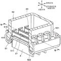
Fig. 2 is an exploded perspective view showing the vicinity of a header of the radiator shown in fig. 1.
Fig. 3 is an exploded perspective view showing the vicinity of a core plate of the radiator shown in fig. 1.
Fig. 4 is a sectional view IV-IV of fig. 3.
Fig. 5 is a V-V sectional view of fig. 3.
Fig. 6 is a cross-sectional view VI-VI of fig. 2.
Fig. 7 is a partially enlarged plan view of the core plate of the second embodiment as viewed from the longitudinal direction.
Fig. 8 is a sectional view VIII-VIII of fig. 7.
Fig. 9 is a partially enlarged sectional view showing a state before a burring portion of the core plate of the second embodiment is formed.
Fig. 10 is a partially enlarged sectional view showing a state after a burring portion of the core plate of the second embodiment is formed.
Fig. 11 is an explanatory view showing the vicinity of the joint between the core plate and the tube according to the second embodiment.
Fig. 12 is an exploded perspective view showing the vicinity of a core plate of a radiator according to a third embodiment.
Fig. 13 is a cross-sectional view XIII-XIII of fig. 12.
Fig. 14 is a partially enlarged perspective view showing a tank body portion of the third embodiment.
Fig. 15 is an explanatory view showing the vicinity of the joint between the core plate and the tube according to the third embodiment.
Detailed Description
Hereinafter, embodiments of the present invention will be described with reference to the drawings. In the following embodiments, the same or equivalent portions are denoted by the same reference numerals in the drawings.
(first embodiment)
A first embodiment of the present invention will be described with reference to the drawings. In the present embodiment, a case will be described as an example in which the heat exchanger of the present invention is applied to an automobile radiator that cools engine cooling water by exchanging heat between the engine cooling water and air.
As shown in fig. 1, a heat sink 1 of the present embodiment includes: a core 4 composed of a plurality of tubes 2 and fins 3, and a pair of headers 5 attached to and disposed at both ends of the core 4.
The pipe 2 is a pipe through which fluid flows. In the present embodiment, the fluid is engine cooling water. The pipe 2 is formed in a flat shape so that the flow direction of the fluid coincides with the longitudinal direction. The plurality of tubes 2 are arranged in parallel with each other in a direction (parallel direction) perpendicular to the longitudinal direction so that the longitudinal direction thereof coincides with the horizontal direction. In the following description, the direction in which the plurality of tubes 2 are arranged is referred to as the parallel direction.
The fins 3 are formed in a corrugated shape and joined to the flat surfaces on both sides of the tube 2. The fins 3 increase the heat transfer area with the air, thereby promoting heat exchange between the engine cooling water flowing through the tubes 2 and the air.
The headers 5 extend in the parallel direction at both ends in the longitudinal direction of the tubes 2 and communicate with the plurality of tubes 2. In the present embodiment, the header 5 is disposed one at each of both ends in the longitudinal direction of the tube 2. The header 5 has: a core plate 51 joined in a state where the pipe 2 is inserted; and a tank main body portion 52 constituting a tank space together with the core plate 51.
In addition, side plates 6 that reinforce the core portions 4 are provided at both end portions of the core portions 4 in the parallel direction. The side plates 6 extend in the longitudinal direction and are connected at both ends thereof to the header 5.
Hereinafter, in the radiator 1, a direction orthogonal to both the longitudinal direction and the parallel direction of the tubes 2 is referred to as a width direction. The width direction is parallel to the air flow direction.
Next, a detailed structure of the header 5 will be described with reference to fig. 2 to 6. In fig. 2, a spacer 53 to be described later is not shown.
As shown in fig. 2, the header 5 includes a core plate 51, a tank main body 52, and a gasket 53 (see fig. 6). The pipe 2 and the side plate 6 are joined to the core plate 51 in an inserted state. The tank main body portion 52 constitutes a space in the header 5 together with the core plate 51. The packing 53 is a seal member for sealing between the core plate 51 and the tank main body 52. In the present embodiment, the core plate 51 is made of an aluminum alloy, and the tank body 52 is made of a resin product such as glass-reinforced polyamide reinforced with glass fibers.
Then, in a state where the spacer 53 is sandwiched between the core plate 51 and the tank main body portion 52, a caulking claw portion 516, described later, of the core plate 51 is pressed against the tank main body portion 52 to be plastically deformed, thereby caulking and fixing the tank main body portion 52 to the core plate 51. The spacer 53 of the present embodiment is formed of an elastically deformable rubber. More specifically, the packing 53 of the present embodiment is formed of ethylene-propylene-diene rubber (EPDM).
As shown in fig. 3, 4 and 5, the core plate 51 has a pipe joint surface 511, a seal surface 512 on which the packing 53 is disposed, and an inclined surface 513 connecting the pipe joint surface 511 and the seal surface 512. In the present embodiment, the pipe joining surface 511 and the sealing surface 512 are parallel to each other. Specifically, the pipe joining surface 511 and the sealing surface 512 are perpendicular to the longitudinal direction.
In the present embodiment, the inclined surface 513 is inclined with respect to the pipe joint surface 511 and the seal surface 512. In other words, the inclined surface 513 is inclined with respect to the longitudinal direction. Specifically, the angle formed by the sealing surface 512 and the inclined surface 513 and the angle formed by the pipe joining surface 511 and the inclined surface 513 are obtuse angles, respectively.
As shown in fig. 6, the tube 2 has an end surface (tube end surface) 20 in the longitudinal direction. The inclined surface 513 is inclined with respect to the longitudinal direction so that the longitudinal distance between the pipe end surface 20 and the pipe engagement surface 511 is different from the longitudinal distance between the pipe end surface 20 and the seal surface 512. In the present embodiment, the longitudinal distance between the pipe joining surface 511 and the pipe end surface 20 is shorter than the longitudinal distance between the sealing surface 512 and the pipe end surface 20. That is, the sealing surface 512 is located further inward (closer to the core 4) in the longitudinal direction of the tube 2 than the tube engagement surface 511.
A plurality of pipe insertion holes (not shown) are formed in the pipe joining surface 511 and the inclined surface 513 in the parallel direction, and the pipes 2 are inserted into the pipe insertion holes and brazed therein. The pipe 2 is joined to the pipe joint surface 511 and the inclined surface 513 in a state where the pipe joint surface 511 and the inclined surface 513 are inserted through the pipe insertion hole. The pipe 2 may be inserted into at least a part of the pipe joining surface 511 and the inclined surface 513.
Further, one side plate insertion hole (not shown) is formed in each of the pipe joining surface 511 and the inclined surface 513 on both ends of the pipe joining surface 511 and the inclined surface 513 in the parallel direction, and the side plate 6 is inserted into and welded to the side plate insertion hole. The side plate 6 is joined to the pipe joint surface 511 and the inclined surface 513 with the joint surface 511 and the inclined surface 513 inserted through the side plate insertion hole.
The core plate 51 has an outer wall portion 515, and the outer wall portion 515 is bent from the sealing surface 512 substantially at right angles to the side opposite to the core 4 and extends in the parallel direction or the air flow direction.
A rib 518 having a surface parallel to the longitudinal direction is provided between adjacent tubes 2 on the inclined surface 513 of the core plate 51. Hereinafter, a surface parallel to the longitudinal direction of the rib 518 is referred to as a parallel surface 517. In the present embodiment, the parallel surface 517 is perpendicular to the air flow direction. The angle formed by the parallel surface 517 and the seal surface 512 is substantially a right angle. In addition, the rib 518 is formed to protrude to the outside of the header 5.
As shown in fig. 2, the length of the box main body portion 52 in the air flow direction is shorter than the length of the tube 2 in the air flow direction. A bulge 521 bulging outward is formed at a position facing the pipe 2 of the tank main body 52. Thus, the inner surface of the tank body 52 is not in contact with the outer surface of the pipe 2.
A flange portion 522 is provided at a portion of the tank main body portion 52 where the adjacent tubes 2 face each other, that is, at a portion where the bulge portion 521 is not formed, and the plate thickness of an end portion of the flange portion 522 on the core plate 51 side is thicker than other portions. The flange portion 522 is disposed on the sealing surface 512 of the core plate 51 via the packing 53.
However, the core plate 51 is provided with a plurality of caulking claws 516. The caulking claw 516 projects from the outer wall 515 toward the box main body 52. The caulking claws 516 are located at positions of the core plate 51 corresponding to the adjacent tubes 2, that is, at positions corresponding to the flange portion 522 of the tank main body portion 52. As shown in fig. 6, the case body 52 is fixed to the core plate 51 by caulking the caulking claws 516 to the flange portion 522 of the case body 52.
As shown in fig. 2 and 3, an inner column portion 21 is provided inside the tube 2, and the inner column portion 21 is formed to connect two flat surfaces to each other, thereby improving the pressure resistance of the tube 2. In the present embodiment, the inner pillar portion 21 is located at the center portion in the air flow direction in the interior of the tube 2. The inner column portion 21 divides the fluid passage inside the tube 2 into two parts.
As described above, in the present embodiment, the tube joint surface 511 and the seal surface 512 are provided in the core plate 51. The lengthwise distance between the tube engaging face 511 and the tube end face 20 is different from the lengthwise distance between the sealing face 512 and the tube end face 20. That is, in the present embodiment, the surface (tube joint surface 511) of the core plate 51 to which the tube 2 is inserted and joined and the surface (sealing surface 512) on which the packing 53 is disposed are not located on the same plane. When the core 51 and the tank main body 52 are swaged, the header 5 is held in contact with the core inclined surface 513. This prevents interference with the pipe 2.
Further, since the spacer 53 abuts against the inclined surface 513 when the core plate 51 and the tank main body portion 52 are caulked, the displacement of the spacer 53 can be suppressed. Specifically, by forming the seal surface 512 between the inclined surface 513 and the outer wall portion 515, the misalignment of the packing 53 can be more reliably suppressed.
In the present embodiment, the pipe 2 is inserted and joined to both the pipe joining surface 511 and the inclined surface 513. This can reduce the dimension of the pipe joining surface 511 in the width direction, and thus reduce the dimension of the header 5 in the width direction. As a result, the dimension of the heat sink 1 in the width direction can be reduced.
However, in the heat exchanger described in patent document 1, the flange portion 522 of the tank main body portion 52 is positioned on the pipe joining surface 511 of the core plate 51. Therefore, in the manufacturing process of the header 5, when the tank body 52 is disposed on the core plate 51, the flange portion 522 may come into contact with the tubes 2, and the tubes 2 may be damaged. When the tank main body 52 and the core plate 51 are caulked, the tank main body 52 is deformed inward of the tank, and the tube 2 may be damaged.
In contrast, in the present embodiment, the core plate 51 has a rib 518 at a portion corresponding to each of the adjacent tubes 2 in the inclined surface 513, and the rib 518 has a parallel surface 517 parallel to the longitudinal direction. Thus, when the tank main body 52 is mounted to the core plate 51, the flange portion 522 of the tank main body 52 abuts against the parallel surface 517 of the rib 518 in the core plate 51. Therefore, the flange portion 522 can be prevented from coming into contact with the pipe 2.
In the present embodiment, the tank main body 52 and the core plate 51 are fixed by caulking in a state where the flange portion 522 of the tank main body 52 is in contact with the parallel surface 517 of the rib 518 in the core plate 51. Therefore, when the tank main body 52 and the core plate 51 are caulked, the tank main body 52 can be suppressed from deforming toward the inside of the tank.
Therefore, in the radiator 1 of the present embodiment, damage to the tube 2 can be reliably suppressed.
Further, since the rib 518 having the parallel surface 517 parallel to the longitudinal direction is provided at a portion of the inclined surface 513 of the core plate 51 corresponding to the adjacent tubes 2, the parallel surface 517 abuts against the flange portion 522 of the tank main body portion 52. Therefore, the tank body 52 can be reliably held when the flange portion 522 is disposed on the core plate 51 and when the tank body 52 and the core plate 51 are caulked.
(second embodiment)
Next, a second embodiment of the present invention will be described with reference to the drawings. The second embodiment is different from the first embodiment in the structure of the core plate 51 in the vicinity of the pipe insertion hole.
As shown in fig. 7, a plurality of tube insertion holes 519 are formed in the tube joining surface 511 and the inclined surface 513 of the core plate 51 in the parallel direction, and the tubes 2 are inserted into and brazed to the tube insertion holes 519. The pipe insertion hole 519 may be formed in the pipe engagement surface 511 and at least a part of the inclined surface 513, and the pipe insertion hole 519 does not necessarily need to be formed over the entire inclined surface 513.
As shown in fig. 7 and 8, a burring 520 protruding toward the end surface 20 (see fig. 11) in the longitudinal direction is provided at the edge of the tube insertion hole 519. The burring 520 is connected to both the pipe joining surface 511 and the inclined surface 513 of the core 51. The burring 520 is formed by burring the edge of the tube insertion hole 519.
Hereinafter, a portion of the burring part 520 that is connected to the tube joining surface 511, that is, that faces the tube joining surface 511 is referred to as a first burring part (first portion) 520 a. A portion of the burring part 520 that is connected to the inclined surface 513, that is, a portion facing the inclined surface 513 is referred to as a second burring part (second portion) 520 b. The first burring part 520a and the second burring part 520b are integrally formed.
As shown in fig. 9, in the pipe joining surface 511, the burring forming direction (see arrow a in fig. 9) of the first burring part 520a is perpendicular to the pipe joining surface 511. In the inclined surface 513, the burring forming direction (see arrow B in fig. 9) of the second burring part 520B is acute with respect to the inclined surface 513. Therefore, the length Lb in the longitudinal direction of the second burring part 520b is longer than the length La in the longitudinal direction of the first burring part 520 a.
As described above, in the present embodiment, the flanged portion 520 protruding toward the end surface 20 in the longitudinal direction is provided at the edge of the tube insertion hole 519. This can improve the strength of the joint between the core plate 51 and the pipe 2, and thus can improve the resistance to thermal deformation (resistance to thermal deformation).
However, as shown in fig. 11, of the joint portions between the core plate 51 and the tubes 2, the joint portion C between the inclined surface 513 and the outer end 22 in the width direction (air flow direction) of the tube 2 is most thermally deformed. Hereinafter, the joint portion C is referred to as a maximum thermal deformation generating portion C.
In contrast, in the present embodiment, the length Lb in the longitudinal direction of the second burring part 520b connected to the inclined surface 513 is made longer than the length La in the longitudinal direction of the first burring part 520a connected to the pipe joint surface 511. Accordingly, the length of the second burring part 520b in the longitudinal direction corresponding to the maximum thermal deformation generating portion C is increased, and therefore the thermal deformation resistance of the maximum thermal deformation generating portion C can be reliably improved.
(third embodiment)
Next, a third embodiment of the present invention will be described with reference to the drawings. In the third embodiment, the core plate 51 and the tank main body 52 are different in structure from those of the first embodiment.
As shown in fig. 12 and 13, a rib 530 protruding in the longitudinal direction is provided between the adjacent tubes 2 on the inclined surface 513 of the core plate 51. The widthwise (air flow) outer end 530a of the rib 530 is located further outward in the width direction than the widthwise outer end 22 of the tube 2. That is, the ribs 530 are provided across the outer end 22 of the tube 2 in the width direction when viewed from the parallel direction. In other words, the rib 530 is provided to extend from the inside to the outside in the width direction of the outer end portion 22 of the tube 2.
As shown in fig. 13, the widthwise inner end 512a of the seal surface 512 of the core plate 51 is located at a position widthwise outward of the outer end 22 of the tube 2. In the present embodiment, the inner end 512a of the seal surface 512 in the width direction is located at a position outside the outer end 530a of the rib 530 in the width direction. In other words, when the direction perpendicular to both the longitudinal direction of the tube 2 and the parallel direction perpendicular to the longitudinal direction of the tube 2 is defined as the width direction, the rib 530 has the outer end 530a in the width direction, and the tube 2 has the outer end 22 in the width direction. The outer end 530a of the rib 530 is located outward in the width direction with respect to the outer end 22 of the pipe 2.
Therefore, when the pipe 2 is viewed from the parallel direction, the outer end 22 of the pipe 2, the outer end 530a of the rib 530, and the inner end 512a of the sealing surface 512 are arranged in this order from the inside toward the outside in the width direction.
In the present embodiment, the outer end 530a of the rib 530 is located on the outer side in the longitudinal direction of the inner end 512a of the sealing surface 512 (the outer side of the core 4). Therefore, in the core plate 51, a step 540 is formed between the inclined surface 513 and the seal surface 512. The outer end 530a of the rib 530 is located inward in the width direction of the step 540.
As shown in fig. 12 and 14, the tank main body portion 52 has a corrugated portion 525 on the inner surface, and the corrugated portion 525 has a plurality of inner crests 523 and a plurality of inner troughs 524 that are alternately arranged. The wavy portion 525 is provided on a surface substantially orthogonal to the width direction of the inner surface of the box main body portion 52.
The inner peak 523 of the wavy portion 525 is located between the adjacent tubes 2. Further, the distance between one of the inner crests 523 and the other inner crest opposing the one inner crest in the width direction is shorter than the length of the tube 2 in the width direction. That is, the inner width of the tank main body portion 52 defined by the inner ridge 523 is shorter than the length of the tube 2 in the width direction. The inner width of the tank body 52 refers to the length in the width direction in the tank body 52.
The inner trough 524 of the wavy portion 525 is located on the outer side in the width direction of the tube 2. Further, the outer end 22 of the tube 2 in the width direction is housed inside the valley portion 524. That is, the outer end 22 of the tube 2 in the width direction is positioned inside the valley portion 524. The inner surface of each inner valley portion 524 is formed in a curved surface shape (circular arc shape in cross section).
As described above, in the present embodiment, the outer end 530a of the rib 530 is located at the widthwise outer side with respect to the outer end 22 of the pipe 2. This can improve the strength of the joint C between the inclined surface 513 of the core plate 51 and the outer end 22 in the width direction (air flow direction) of the tube 2. Therefore, the heat distortion resistance of the maximum thermal distortion generating portion C in the joint portion between the core plate 51 and the tube 2 can be reliably improved.
In the present embodiment, the inner end 512a of the seal surface 512 is located outward in the width direction of the outer end 530a of the rib 530. As a result, as shown in fig. 15, when thermal deformation occurs, the core plate 51 is easily bent with the inner end 512a of the seal surface 512 as a base point. Therefore, the thermal deformation can be absorbed by deforming the core plate 51.
Further, in the present embodiment, a step 540 is formed between the inclined surface 513 and the seal surface 512 in the core plate 51, and the outer end 530a of the rib 530 is positioned inward in the width direction of the step 540. Thus, since the core plate 51 has a strength difference due to the step 540, when thermal deformation occurs, the core plate 51 can be bent more positively using the step 540 as a bending base point.
When the inner end 512a of the seal surface 512 is positioned inward in the width direction of the outer end 530a of the rib 530, the rib 530 increases the strength of the inner end 512a of the seal surface 512. Therefore, when thermal deformation occurs, it is difficult to bend the core plate 51 with the inner end 512a of the seal surface 512 as a base point.
In the present embodiment, the inner surface of the inner trough portion 524 is formed in a curved surface shape. Therefore, stress concentration is suppressed in the valley portions 524, and the pressure resistance of the header 5 can be improved. Further, by providing the inner trough 524 on the inner surface of the tank main body 52, it is not necessary to provide the raised portion 521 on the outer surface of the tank main body 52 corresponding to the inner trough 534. This can form the outer surface of the box main body portion 52 flat, and thus can improve the degree of freedom in designing the caulking claw portion 516 of the core plate 51.
(other embodiments)
The present invention is not limited to the above-described embodiments, and various modifications can be made as follows without departing from the scope of the present invention. Further, the technical features disclosed in the above embodiments may be appropriately combined within a practicable range.
(1) In the above embodiment, the example in which the angle formed by the seal surface 512 and the inclined surface 513 is an obtuse angle was described, but for example, the angle formed by the seal surface 512 and the inclined surface 513 may be a right angle. That is, the inclined surface 513 may be perpendicular to the sealing surface 512.
(2) In the above embodiment, an example in which the entire surface of the pipe joining surface 511 is parallel to the sealing surface 512 has been described. However, a part of the pipe joining surface 511, for example, a central part in the width direction of the header 5 may be parallel to the sealing surface 512.
(3) In the above embodiment, an example in which the heat exchanger of the present invention is applied to the radiator 1 is described. However, the heat exchanger of the present invention may be applied to other heat exchangers such as an evaporator and a refrigerant radiator (refrigerant condenser).
(4) In the above embodiment, an example in which the spacer 53 is configured separately from the core plate 51 and the tank main body portion 52 has been described. However, the structure of the spacer 53 is not limited thereto. For example, the spacer 53 may be bonded to or integrally formed with one of the core plate 51 and the tank main body 52 by an adhesive or the like.
(5) In the above embodiment, an example in which the caulking claw portions 516 of the bent core plate 51 are fixed to the flange portion 522 of the box main body portion 52 by caulking has been described. However, the fixing structure by caulking of the core plate 51 is not limited thereto. For example, a slit formed in a part of the outer wall portion 515 of the core plate 51 may be plastically deformed in the air flow direction and engaged with an uneven portion formed in the flange portion 522 of the tank main body portion 52, thereby fixing the core plate 51 and the tank main body portion 52 by caulking.
Claims (8)
1. A header of a heat exchanger having a plurality of tubes (2) stacked in a parallel direction, the plurality of tubes (2) having a fluid flowing therein, the header of the heat exchanger being characterized by comprising:
a core plate (51), the core plate (51) being joined to the ends of the plurality of tubes (2) in the longitudinal direction; and
a tank main body portion (52) that is fixed to the core plate (51), and that forms a tank space that communicates with the plurality of tubes (2) together with the core plate (51),
when the direction orthogonal to both the parallel direction and the longitudinal direction is taken as the width direction, the box main body part (52) comprises:
an inner surface on which a wavy portion (525) is formed, the wavy portion (525) having a plurality of inner crests (523) and a plurality of inner troughs (524) that are alternately arranged; and
a flat outer surface opposed to the inner surface in the width direction,
a distance between one of the plurality of inner crests (523) and the other inner crest (523) opposite to the one inner crest (523) in the width direction is smaller than a length of the pipe (2) in the width direction,
an elastically deformable sealing member (53) is provided, the sealing member (53) seals between the core plate (51) and the tank body (52),
the core plate (51) has:
a tube engaging face (511);
a seal surface (512) on which the seal member (53) is disposed; and
an inclined surface (513), the inclined surface (513) connecting between the pipe joining surface (511) and the seal surface (512),
the inclined surface (513) is inclined with respect to the longitudinal direction,
the core plate (51) has a plurality of ribs (530) provided on the inclined surface (513), and the plurality of ribs (530) are opposed to the plurality of inner crests (523) of the tank main body portion (52).
2. A header for a heat exchanger according to claim 1,
the valley portion (524) is formed so as to be able to receive an outer end portion (22) of the plurality of tubes (2) in the width direction.
3. A header for a heat exchanger according to claim 2,
the inner surface of the valley portion 524 is curved.
4. A header for a heat exchanger according to claim 1,
the inclined surface (513) is inclined with respect to the sealing surface (512).
5. A header for a heat exchanger according to claim 1,
at least a portion of the tube engaging surface (511) is parallel to the sealing surface (512).
6. A header for a heat exchanger according to claim 1,
the plurality of ribs (530) having a plurality of outer side ends (530a) in the width direction,
the seal surface (512) has an inner end (512a) in the width direction,
the inner end (512a) is located outward in the width direction with respect to each of the plurality of outer ends (530a) of the plurality of ribs (530).
7. A header for a heat exchanger according to claim 1,
the core plate (51) having a step (540) disposed between the inclined surface (513) and the sealing surface (512),
the plurality of ribs (530) having a plurality of outer side ends (530a) in the width direction,
the outer ends (530a) are respectively located on the inner side in the width direction with respect to the step (540).
8. The header of a heat exchanger according to any one of claims 1 to 7,
the tank body portion (52) is fixed to the core plate by caulking.
Applications Claiming Priority (5)
| Application Number | Priority Date | Filing Date | Title |
|---|---|---|---|
| JP2013-244749 | 2013-11-27 | ||
| JP2013244749 | 2013-11-27 | ||
| JP2014179461A JP6394202B2 (en) | 2013-11-27 | 2014-09-03 | Heat exchanger |
| JP2014-179461 | 2014-09-03 | ||
| CN201480064670.8A CN105793663B (en) | 2013-11-27 | 2014-11-19 | Heat exchanger |
Related Parent Applications (1)
| Application Number | Title | Priority Date | Filing Date |
|---|---|---|---|
| CN201480064670.8A Division CN105793663B (en) | 2013-11-27 | 2014-11-19 | Heat exchanger |
Publications (2)
| Publication Number | Publication Date |
|---|---|
| CN109029053A CN109029053A (en) | 2018-12-18 |
| CN109029053B true CN109029053B (en) | 2020-12-15 |
Family
ID=53198626
Family Applications (2)
| Application Number | Title | Priority Date | Filing Date |
|---|---|---|---|
| CN201480064670.8A Expired - Fee Related CN105793663B (en) | 2013-11-27 | 2014-11-19 | Heat exchanger |
| CN201810725261.8A Active CN109029053B (en) | 2013-11-27 | 2014-11-19 | Header for heat exchanger |
Family Applications Before (1)
| Application Number | Title | Priority Date | Filing Date |
|---|---|---|---|
| CN201480064670.8A Expired - Fee Related CN105793663B (en) | 2013-11-27 | 2014-11-19 | Heat exchanger |
Country Status (5)
| Country | Link |
|---|---|
| US (2) | US10317148B2 (en) |
| EP (1) | EP3076118A4 (en) |
| JP (1) | JP6394202B2 (en) |
| CN (2) | CN105793663B (en) |
| WO (1) | WO2015079653A1 (en) |
Families Citing this family (14)
| Publication number | Priority date | Publication date | Assignee | Title |
|---|---|---|---|---|
| DE112016003219T5 (en) * | 2015-07-17 | 2019-05-09 | Denso Corporation | heat exchangers |
| US10126064B2 (en) | 2015-08-07 | 2018-11-13 | Denso Corporation | Heat exchanger |
| JP6547576B2 (en) * | 2015-10-15 | 2019-07-24 | 株式会社デンソー | Heat exchanger |
| EP3367039B1 (en) * | 2015-10-22 | 2021-04-14 | T.RAD Co., Ltd. | Heat exchanger |
| JP6610777B2 (en) * | 2016-04-20 | 2019-11-27 | 株式会社デンソー | Heat exchanger and manufacturing method thereof |
| JP6449811B2 (en) * | 2016-06-09 | 2019-01-09 | カルソニックカンセイ株式会社 | Heat exchanger |
| DE102018111556A1 (en) | 2017-06-22 | 2018-12-27 | Hanon Systems | Heat exchanger |
| JP6919472B2 (en) * | 2017-09-29 | 2021-08-18 | 株式会社デンソー | Heat exchanger |
| CN108180778B (en) * | 2017-12-28 | 2024-05-10 | 天津市华迪汽车散热器有限公司 | Sealing structure of radiator main board and water chamber |
| DE102018219171A1 (en) | 2018-06-29 | 2020-01-02 | Hanon Systems | battery cooler |
| DE102018220139A1 (en) | 2018-11-23 | 2020-05-28 | Mahle International Gmbh | Collecting pipe for a heat exchanger |
| DE102018220142A1 (en) * | 2018-11-23 | 2020-05-28 | Mahle International Gmbh | Collecting pipe for a heat exchanger |
| DE102018220143A1 (en) | 2018-11-23 | 2020-05-28 | Mahle International Gmbh | Collecting pipe for a heat exchanger |
| KR20210105553A (en) * | 2020-02-19 | 2021-08-27 | 한온시스템 주식회사 | Heat exchanger having header structure dispersing thermal stress |
Citations (3)
| Publication number | Priority date | Publication date | Assignee | Title |
|---|---|---|---|---|
| DE102007027706A1 (en) * | 2007-06-15 | 2008-12-18 | Modine Manufacturing Co., Racine | heat exchangers |
| DE102011076225A1 (en) * | 2011-05-20 | 2012-11-22 | Behr Gmbh & Co. Kg | heat exchangers |
| DE102012004926A1 (en) * | 2012-03-10 | 2013-09-12 | Volkswagen Aktiengesellschaft | Heat exchanger with a tubesheet and a dedicated tube plate |
Family Cites Families (54)
| Publication number | Priority date | Publication date | Assignee | Title |
|---|---|---|---|---|
| DE2852408B2 (en) | 1978-12-04 | 1981-10-01 | Süddeutsche Kühlerfabrik Julius Fr. Behr GmbH & Co KG, 7000 Stuttgart | Clamp connection |
| US4881594A (en) * | 1989-03-27 | 1989-11-21 | General Motors Corporation | Header plate for pressure vessels, heat exchangers and the like |
| JPH0346776U (en) * | 1989-08-30 | 1991-04-30 | ||
| US4997035A (en) * | 1990-04-02 | 1991-03-05 | Blackstone Corporation | Joint crevice corrosion inhibitor |
| US4971145A (en) * | 1990-04-09 | 1990-11-20 | General Motors Corporation | Heat exchanger header |
| JPH04108186A (en) | 1990-08-25 | 1992-04-09 | Apisu:Kk | Leather and production thereof |
| JP2514456Y2 (en) | 1991-02-21 | 1996-10-16 | サンデン株式会社 | Heat exchanger |
| US5195579A (en) * | 1992-07-20 | 1993-03-23 | General Motors Corporation | Integral tab lock and bracket assembly for headered tube condenser |
| DE4442040A1 (en) * | 1994-11-25 | 1996-05-30 | Behr Gmbh & Co | Heat exchanger with a manifold |
| US5842515A (en) * | 1995-09-30 | 1998-12-01 | Halla Climate Control Corporation | Heat exchanger and method of manufacturing header pipe for the same |
| FR2742532B1 (en) * | 1995-12-13 | 1998-01-30 | Valeo Thermique Moteur Sa | REDUCED SIZE COLLECTOR PLATE FOR HEAT EXCHANGER |
| CN1162107A (en) | 1995-12-13 | 1997-10-15 | 瓦莱奥热机公司 | Volume-reduced collector plate for heat exchanger |
| FR2745079B1 (en) * | 1996-02-20 | 1998-04-10 | Valeo Thermique Moteur Sa | BRAZED FLUID BOX HEAT EXCHANGER, ESPECIALLY FOR MOTOR VEHICLES |
| JP3414171B2 (en) * | 1996-11-29 | 2003-06-09 | 株式会社デンソー | Heat exchanger |
| US5899267A (en) * | 1998-09-14 | 1999-05-04 | General Motors Corporation | Heat exchanger sealed tank and header assembly with gasket displacement prevention |
| US6640887B2 (en) * | 2000-12-20 | 2003-11-04 | Visteon Global Technologies, Inc. | Two piece heat exchanger manifold |
| DE10103176B4 (en) * | 2001-01-22 | 2010-06-02 | Behr Gmbh & Co. Kg | Method for introducing Flachrohreinsteckschlitzen in a manifold |
| JP3675348B2 (en) * | 2001-03-23 | 2005-07-27 | 株式会社デンソー | Heat exchanger |
| JP2004301455A (en) * | 2003-03-31 | 2004-10-28 | Calsonic Kansei Corp | Header tank for heat exchanger |
| CN100541108C (en) * | 2003-08-01 | 2009-09-16 | 昭和电工株式会社 | Header and heat exchanger with this header |
| US7426958B2 (en) | 2003-08-19 | 2008-09-23 | Visteon Global Technologies Inc. | Header for heat exchanger |
| ES2805502T3 (en) * | 2003-12-19 | 2021-02-12 | Valeo Inc | Sleeve rib for heat exchange tanks |
| JP2005308366A (en) * | 2004-04-26 | 2005-11-04 | T Rad Co Ltd | Heat exchanger |
| JP2006162194A (en) | 2004-12-09 | 2006-06-22 | Denso Corp | Heat exchanger |
| JP2006189206A (en) * | 2005-01-06 | 2006-07-20 | Denso Corp | Heat exchanger |
| US20080135220A1 (en) | 2005-02-03 | 2008-06-12 | Behr Gmbh & Co., Kg | Heat Exchanger |
| JP2006284107A (en) * | 2005-04-01 | 2006-10-19 | Denso Corp | Heat exchanger |
| DE102006019536A1 (en) * | 2006-04-27 | 2007-10-31 | Modine Manufacturing Co., Racine | Collecting box for a heat exchanger in an air conditioning system comprises a side having a protruding recess with an arc-like convex contour extending over a part of the width of the side |
| US7621165B2 (en) * | 2006-06-29 | 2009-11-24 | Wheeling-Corrugating Company | Crimp tool |
| CN100498190C (en) * | 2006-06-29 | 2009-06-10 | 株式会社电装 | Heat exchanger |
| JP5029166B2 (en) * | 2006-06-29 | 2012-09-19 | 株式会社デンソー | Heat exchanger |
| DE102007028792A1 (en) * | 2006-06-29 | 2008-01-31 | Denso Corp., Kariya | heat exchangers |
| FR2904101B1 (en) | 2006-07-21 | 2008-09-05 | Valeo Systemes Thermiques | HEAT EXCHANGER WITH IMPROVED COLLECTOR |
| KR100837814B1 (en) * | 2006-12-22 | 2008-06-13 | 주식회사 하이닉스반도체 | Circuit for outputting data of semiconductor memory apparatus |
| KR20090011216A (en) * | 2007-07-25 | 2009-02-02 | 삼성전자주식회사 | Apparatus for filtering air and cleaning system of semiconductor manufacturing equipment used the same |
| CN101918785B (en) * | 2007-11-01 | 2013-12-18 | 摩丁制造公司 | Heat exchanger |
| US7921558B2 (en) * | 2008-01-09 | 2011-04-12 | Delphi Technologies, Inc. | Non-cylindrical refrigerant conduit and method of making same |
| FR2927412B1 (en) | 2008-02-13 | 2012-12-21 | Valeo Systemes Thermiques | COLLECTOR PLATE WITHOUT THROAT |
| US20090255657A1 (en) * | 2008-04-15 | 2009-10-15 | Denso Corporation | Heat exchanger and method of manufacturing the same |
| JP4600506B2 (en) * | 2008-04-15 | 2010-12-15 | 株式会社デンソー | Manufacturing method of heat exchanger |
| JP2011099631A (en) * | 2009-11-06 | 2011-05-19 | Denso Corp | Heat exchanger |
| FR2952711B1 (en) | 2009-11-19 | 2012-01-20 | Valeo Systemes Thermiques | COLLECTOR PLATE, COLLECTOR BOX COMPRISING SUCH A PLATE AND HEAT EXCHANGER EQUIPPED WITH SUCH A BOX |
| DE102011008220A1 (en) * | 2010-01-13 | 2012-01-19 | Denso Corporation | heat exchangers |
| ES2711572T3 (en) * | 2010-03-31 | 2019-05-06 | Modine Mfg Co | Heat exchanger |
| US20110240276A1 (en) * | 2010-04-01 | 2011-10-06 | Delphi Technologies, Inc. | Heat exchanger having an inlet distributor and outlet collector |
| US8536834B2 (en) * | 2010-12-23 | 2013-09-17 | Thermo King Corporation | Mobile environment-controlled unit and method of operating a mobile environment-controlled unit |
| KR20120074846A (en) * | 2010-12-28 | 2012-07-06 | 한라공조주식회사 | Intercooler |
| JP5541218B2 (en) * | 2011-04-01 | 2014-07-09 | 株式会社デンソー | Heat exchanger |
| DE102012202886A1 (en) * | 2012-02-24 | 2013-08-29 | Behr Gmbh & Co. Kg | Heat exchanger for motor vehicles, has pipe, block with ribs, pipe base and collecting box, where base area of pipe base is formed in curved shape with low point that is deeply arranged opposite to outer areas |
| JP6337442B2 (en) * | 2013-10-30 | 2018-06-06 | 株式会社デンソー | Heat exchanger |
| JP2015206507A (en) * | 2014-04-18 | 2015-11-19 | 株式会社デンソー | heat exchanger |
| JP6384344B2 (en) * | 2015-02-05 | 2018-09-05 | 株式会社デンソー | Heat exchanger |
| DE112016003219T5 (en) * | 2015-07-17 | 2019-05-09 | Denso Corporation | heat exchangers |
| JP6547576B2 (en) * | 2015-10-15 | 2019-07-24 | 株式会社デンソー | Heat exchanger |
-
2014
- 2014-09-03 JP JP2014179461A patent/JP6394202B2/en active Active
- 2014-11-19 CN CN201480064670.8A patent/CN105793663B/en not_active Expired - Fee Related
- 2014-11-19 US US15/039,063 patent/US10317148B2/en active Active
- 2014-11-19 WO PCT/JP2014/005793 patent/WO2015079653A1/en active Application Filing
- 2014-11-19 EP EP14866522.7A patent/EP3076118A4/en not_active Withdrawn
- 2014-11-19 CN CN201810725261.8A patent/CN109029053B/en active Active
-
2019
- 2019-04-25 US US16/394,297 patent/US11162743B2/en active Active
Patent Citations (3)
| Publication number | Priority date | Publication date | Assignee | Title |
|---|---|---|---|---|
| DE102007027706A1 (en) * | 2007-06-15 | 2008-12-18 | Modine Manufacturing Co., Racine | heat exchangers |
| DE102011076225A1 (en) * | 2011-05-20 | 2012-11-22 | Behr Gmbh & Co. Kg | heat exchangers |
| DE102012004926A1 (en) * | 2012-03-10 | 2013-09-12 | Volkswagen Aktiengesellschaft | Heat exchanger with a tubesheet and a dedicated tube plate |
Also Published As
| Publication number | Publication date |
|---|---|
| US20170038163A1 (en) | 2017-02-09 |
| WO2015079653A1 (en) | 2015-06-04 |
| JP6394202B2 (en) | 2018-09-26 |
| US11162743B2 (en) | 2021-11-02 |
| EP3076118A1 (en) | 2016-10-05 |
| CN109029053A (en) | 2018-12-18 |
| CN105793663B (en) | 2018-08-07 |
| US10317148B2 (en) | 2019-06-11 |
| CN105793663A (en) | 2016-07-20 |
| JP2015127631A (en) | 2015-07-09 |
| US20190249936A1 (en) | 2019-08-15 |
| EP3076118A4 (en) | 2017-08-16 |
Similar Documents
| Publication | Publication Date | Title |
|---|---|---|
| CN109029053B (en) | Header for heat exchanger | |
| US11255609B2 (en) | Heat exchanger | |
| CN108139183B (en) | heat exchanger | |
| US6305465B1 (en) | Double heat exchanger having condenser core and radiator core | |
| US10401095B2 (en) | Heat exchanger | |
| US20080121386A1 (en) | Method of manufacturing header tank for heat exchanger and heat exchanger having the header tank | |
| US7823630B2 (en) | Tube for heat exchanger and method of manufacturing tube | |
| WO2017013918A1 (en) | Heat exchanger | |
| US20060113069A1 (en) | Heat exchanger | |
| WO2015159529A1 (en) | Heat exchanger | |
| JP2009216151A (en) | Sealing structure and heat exchanger using the same | |
| US8448698B2 (en) | Tube for heat exchanger | |
| JP2020003089A (en) | Heat exchange tube and heat exchanger | |
| JP2008261550A (en) | Heat exchanger and its manufacturing method | |
| JP4506435B2 (en) | Heat exchanger | |
| JP2005127676A (en) | Heat exchanger, and manufacturing method of heat exchanger | |
| JP2006200862A (en) | Flat tube for heat exchanger | |
| JP6992581B2 (en) | Heat exchanger | |
| JP6919472B2 (en) | Heat exchanger | |
| WO2014147997A1 (en) | Heat exchanger | |
| KR100733072B1 (en) | Radiator cooler head and manufacturing method thereof | |
| CN113924449A (en) | Heat exchanger | |
| JP2018017416A (en) | Heat exchanger |
Legal Events
| Date | Code | Title | Description |
|---|---|---|---|
| PB01 | Publication | ||
| PB01 | Publication | ||
| SE01 | Entry into force of request for substantive examination | ||
| SE01 | Entry into force of request for substantive examination | ||
| GR01 | Patent grant | ||
| GR01 | Patent grant |