KR20120074846A - Intercooler - Google Patents
Intercooler Download PDFInfo
- Publication number
- KR20120074846A KR20120074846A KR1020100136808A KR20100136808A KR20120074846A KR 20120074846 A KR20120074846 A KR 20120074846A KR 1020100136808 A KR1020100136808 A KR 1020100136808A KR 20100136808 A KR20100136808 A KR 20100136808A KR 20120074846 A KR20120074846 A KR 20120074846A
- Authority
- KR
- South Korea
- Prior art keywords
- tube
- header
- intercooler
- tube hole
- tubes
- Prior art date
Links
Images


Classifications
-
- F—MECHANICAL ENGINEERING; LIGHTING; HEATING; WEAPONS; BLASTING
- F02—COMBUSTION ENGINES; HOT-GAS OR COMBUSTION-PRODUCT ENGINE PLANTS
- F02B—INTERNAL-COMBUSTION PISTON ENGINES; COMBUSTION ENGINES IN GENERAL
- F02B29/00—Engines characterised by provision for charging or scavenging not provided for in groups F02B25/00, F02B27/00 or F02B33/00 - F02B39/00; Details thereof
- F02B29/04—Cooling of air intake supply
- F02B29/0406—Layout of the intake air cooling or coolant circuit
- F02B29/0425—Air cooled heat exchangers
-
- F—MECHANICAL ENGINEERING; LIGHTING; HEATING; WEAPONS; BLASTING
- F02—COMBUSTION ENGINES; HOT-GAS OR COMBUSTION-PRODUCT ENGINE PLANTS
- F02B—INTERNAL-COMBUSTION PISTON ENGINES; COMBUSTION ENGINES IN GENERAL
- F02B29/00—Engines characterised by provision for charging or scavenging not provided for in groups F02B25/00, F02B27/00 or F02B33/00 - F02B39/00; Details thereof
- F02B29/04—Cooling of air intake supply
- F02B29/045—Constructional details of the heat exchangers, e.g. pipes, plates, ribs, insulation, materials, or manufacturing and assembly
- F02B29/0456—Air cooled heat exchangers
-
- F—MECHANICAL ENGINEERING; LIGHTING; HEATING; WEAPONS; BLASTING
- F28—HEAT EXCHANGE IN GENERAL
- F28F—DETAILS OF HEAT-EXCHANGE AND HEAT-TRANSFER APPARATUS, OF GENERAL APPLICATION
- F28F9/00—Casings; Header boxes; Auxiliary supports for elements; Auxiliary members within casings
- F28F9/02—Header boxes; End plates
-
- Y—GENERAL TAGGING OF NEW TECHNOLOGICAL DEVELOPMENTS; GENERAL TAGGING OF CROSS-SECTIONAL TECHNOLOGIES SPANNING OVER SEVERAL SECTIONS OF THE IPC; TECHNICAL SUBJECTS COVERED BY FORMER USPC CROSS-REFERENCE ART COLLECTIONS [XRACs] AND DIGESTS
- Y02—TECHNOLOGIES OR APPLICATIONS FOR MITIGATION OR ADAPTATION AGAINST CLIMATE CHANGE
- Y02T—CLIMATE CHANGE MITIGATION TECHNOLOGIES RELATED TO TRANSPORTATION
- Y02T10/00—Road transport of goods or passengers
- Y02T10/10—Internal combustion engine [ICE] based vehicles
- Y02T10/12—Improving ICE efficiencies
Landscapes
- Engineering & Computer Science (AREA)
- Physics & Mathematics (AREA)
- Thermal Sciences (AREA)
- Mechanical Engineering (AREA)
- General Engineering & Computer Science (AREA)
- Chemical & Material Sciences (AREA)
- Combustion & Propulsion (AREA)
- Heat-Exchange Devices With Radiators And Conduit Assemblies (AREA)
Abstract
Description
본 발명은 인터쿨러에 관한 것으로, 보다 상세하게는 내구성을 높이는 구조를 가지는 인터쿨러에 관한 것이다.The present invention relates to an intercooler, and more particularly, to an intercooler having a structure for increasing durability.
인터쿨러(intercooler)는, 엔진 출력을 높이기 위해 과급기에 의해 고온 고압으로 압축된 공기를 식혀 주는 장치이다. 엔진의 출력을 높이기 위해서는 실린더에 고압으로 압축된 공기를 유입시켜 주는 것이 좋으나, 문제는 공기가 압축되는 과정에서 온도가 올라가게 되며, 온도가 올라가면 산소의 밀도가 떨어져 결과적으로 실린더 내의 충전 효율이 오히려 떨어지게 되는 문제점이 발생한다. 이와 같은 문제점을 해소하기 위하여 압축 공기를 식혀주는 인터쿨러를 장착하는데, 인터쿨러에 의해 과급된 공기가 식혀짐으로써 엔진의 연소 효율이 향상되어 연비가 좋아지고 이산화탄소 배출량도 크게 줄어드는 등의 효과가 있어, 특히 발열량이 많은 고성능 엔진 장착 차량에는 반드시 필요한 구성 부품이다.
An intercooler is a device that cools the air compressed at a high temperature and high pressure by a supercharger to increase the engine output. In order to increase the output of the engine, it is recommended to inject the compressed air into the cylinder at high pressure, but the problem is that the temperature rises during the process of compressing the air. The problem of falling occurs. In order to solve this problem, an intercooler for cooling compressed air is installed, and the supercharged air is cooled by the intercooler to improve the combustion efficiency of the engine, thereby improving fuel efficiency and greatly reducing carbon dioxide emissions. It is an essential component for vehicles with high heat generation and high performance engine.
도 1은 일반적인 인터쿨러를 도시한 것이다. 인터쿨러(100)는 도시된 바와 같이 쿨링 모듈(200)의 후방 하면(미도시) 또는 측면(도 1) 등과 같은 위치에 구비된다. 여기에서 쿨링 모듈(200)은 라디에이터 등과 같은 차량 냉각 시스템 또는 공조 시스템을 구성하는 열교환기로서, 차량에 따라 열교환기의 배치 위치가 다양하게 변화하기 때문에 쿨링 모듈(200)로 통칭하였다. 상기 도 1에 도시되어 있는 인터쿨러(100)는 공랭식으로서, 즉 차량 엔진 룸으로 유입되는 공기를 통과시켜 상기 인터쿨러(100) 내의 공기와 외부 공기 간의 열교환을 일으킴으로써 상기 인터쿨러(100) 내의 공기 온도를 낮추도록 되어 있다.1 illustrates a general intercooler. As shown, the
이러한 인터쿨러(100)는, 일반적인 열교환기와 유사하게 외부 공기 송풍 방향에 나란하게 병렬 배치된 복수 개의 튜브 및 상기 복수 개의 튜브의 양쪽에 구비되어 내부로 압축 공기를 유통시키는 한 쌍의 헤더탱크를 포함하여 이루어지며, 열교환성능을 더욱 높이기 위해 튜브 사이에는 핀이 개재되어 이루어질 수도 있다.The
한편, 인터쿨러는 상술한 바와 같이 엔진 과급기에 의하여 고온 고압으로 압축된 공기를 내부로 통과시키면서 외부와 열교환시켜 냉각시키는 장치로서, 즉 열 및 압력의 변화에 의한 피로 영향이 상당히 크게 나타난다는 문제점이 있었다. 특히 인터쿨러의 튜브 및 헤더 간 결합부에서 손상이 잘 발생되었으며, 이에 따라 인터쿨러 자체의 내구성이 크게 떨어지는 문제가 있었다.
On the other hand, the intercooler is a device for heat-exchanging with the outside while passing through the air compressed by the high temperature and high pressure by the engine supercharger as described above, that is, there was a problem that the fatigue effect due to the change of heat and pressure appears significantly . In particular, damage occurred in the coupling portion between the tube and the header of the intercooler, and thus there was a problem that the durability of the intercooler itself was greatly reduced.
따라서, 본 발명은 상기한 바와 같은 종래 기술의 문제점을 해결하기 위하여 안출된 것으로, 본 발명의 목적은 인터쿨러의 헤더에서 튜브 및 헤더 간 결합 부분에서의 응력 집중을 분산시켜 주는 구조를 가지는 인터쿨러를 제공함에 있다.
Accordingly, the present invention has been made to solve the problems of the prior art as described above, an object of the present invention to provide an intercooler having a structure that distributes the stress concentration in the coupling portion between the tube and the header in the header of the intercooler. Is in.
상기한 바와 같은 목적을 달성하기 위한 본 발명의 인터쿨러는, 외부 공기 송풍 방향에 나란하게 병렬 배치된 복수 개의 튜브(120); 및 상기 복수 개의 튜브(120)의 양쪽에 구비되어 내부로 압축 공기를 유통시키는 한 쌍의 헤더탱크(110); 를 포함하여 이루어지는 인터쿨러(100)에 있어서, 상기 헤더탱크(110)는 상기 튜브(120)가 삽입 결합되는 튜브 홀(111a)이 형성되는 헤더(111) 및 상기 헤더(111)와 결합되어 내부에 압축 공기가 유통되는 공간을 형성하는 탱크(112)로 이루어지되, 상기 튜브(120)가 연장되는 방향을 제1방향, 상기 튜브(120)의 폭 방향을 제2방향, 제1방향 및 제2방향과 수직인 방향을 제3방향이라 할 때, 상기 헤더(111)의 상기 튜브(120)의 제2방향 양쪽 끝단 부분에는 제1방향에 대하여 경사지게 형성되며 상기 튜브(120)를 중심으로 서로 대칭으로 이루어지는 한 쌍의 경사부(S)가 형성되며, 상기 튜브 홀(111a)은 상기 경사부(S)까지 연장되어 형성되고, 상기 튜브 홀(111a)의 둘레 전체에 걸쳐 상기 튜브(120)를 감싸도록 플랜지(f)가 형성되는 것을 특징으로 한다.The intercooler of the present invention for achieving the above object, a plurality of
이 때, 상기 경사부(S)는 상기 헤더탱크(110)의 외측 방향을 향하여 돌출되는 형태로 형성되는 것을 특징으로 한다.At this time, the inclined portion (S) is characterized in that it is formed in a form protruding toward the outer direction of the header tank (110).
또한, 상기 경사부(S)는 상기 헤더(111)의 바닥면으로부터의 높이(H)가 3mm 내지 10mm 범위 내의 값으로 이루어지고, 경사각(θ)이 30ㅀ 내지 60ㅀ 범위 내의 값으로 이루어지는 것을 특징으로 한다.In addition, the inclined portion S is a height H from the bottom surface of the
또한, 상기 튜브 홀(111a)은 상기 플랜지(f)가 상기 헤더탱크(110)의 외측 방향으로 돌출되어 형성되는 것을 특징으로 한다.In addition, the
또한, 상기 튜브 홀(111a)은 상기 플랜지(f)의 높이(h)가 2mm 내지 5mm 범위 내의 값으로 이루어지는 것을 특징으로 한다.
In addition, the
본 발명에 의하면, 고온 고압의 압축공기가 유통되는 인터쿨러에 있어서 특히 응력이 집중되어 파손이 발생하기 쉬운 부분인 튜브 및 헤더 간 결합부의 구조를 개선함으로써, 결합부에서의 파손 및 손상 발생 가능성을 크게 줄이고 이에 따라 인터쿨러의 내구성을 증대시킬 수 있는 효과가 있다. 구체적으로는, 본 발명에 의하면 튜브가 결합되는 인터쿨러 튜브 홀의 구조를 개선함으로써 결합 부분에서의 응력을 분산시켜, 특정 부위에 응력이 집중됨으로써 피로 등에 의해 손상이 일어날 가능성을 크게 낮추어 주는 효과가 있는 것이다.
According to the present invention, in the intercooler in which compressed air of high temperature and high pressure flows through, the structure of the coupling portion between the tube and the header, which is a portion where stress is concentrated and breakage is likely to occur, greatly increases the possibility of breakage and damage at the coupling portion. Reduce and thereby increase the durability of the intercooler. Specifically, according to the present invention, by improving the structure of the intercooler tube hole to which the tube is coupled, the stress at the joint portion is dispersed, and the stress is concentrated at a specific site, thereby greatly reducing the possibility of damage caused by fatigue or the like. .
도 1은 일반적인 인터쿨러의 배치 사시도.
도 2는 일반적인 인터쿨러.
도 3은 본 발명의 인터쿨러의 일부 상세도.
도 4는 종래의 인터쿨러에서의 응력 분포.
도 5는 종래 및 본 발명의 인터쿨러 헤더 단면 형태 비교.1 is a layout perspective view of a typical intercooler.
2 is a typical intercooler.
3 is a partial detail view of the intercooler of the present invention.
4 is a stress distribution in a conventional intercooler.
Figure 5 is a comparison of the cross-sectional shape of the conventional and the present invention intercooler header.
이하, 상기한 바와 같은 구성을 가지는 본 발명에 의한 인터쿨러를 첨부된 도면을 참고하여 상세하게 설명한다.
Hereinafter, an intercooler according to the present invention having the configuration as described above will be described in detail with reference to the accompanying drawings.
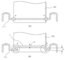
도 2는 일반적인 인터쿨러의 형태를 도시하고 있다. 도 2에 도시된 사시도에서와 같이, 인터쿨러(100)는 외부 공기 송풍 방향에 나란하게 병렬 배치된 복수 개의 튜브(120); 및 상기 복수 개의 튜브(120)의 양쪽에 구비되어 내부로 압축 공기를 유통시키는 한 쌍의 헤더탱크(110); 를 포함하여 이루어진다. 도시된 바와 같이, 상기 인터쿨러(100)는 내부에 유통되는 압축 공기와 외부 공기 간의 열교환효율을 보다 높이기 위하여 상기 튜브(120) 내부에 삽입되거나 또는 상기 튜브(120)들 사이에 개재되는 핀을 더 포함하여 이루어질 수 있다. 상기 헤더탱크(110)는 상기 튜브(120)가 삽입 결합되는 튜브 홀(111a)이 형성되는 헤더(111) 및 상기 헤더(111)와 결합되어 내부에 압축 공기가 유통되는 공간을 형성하는 탱크(112)로 이루어지게 된다.2 shows the shape of a general intercooler. As in the perspective view shown in FIG. 2, the
본 발명에서는 상기 튜브(120)와 결합되는 부분의 형상을 개선함으로써 종래에 이 부분에 응력이 집중되어 파손 및 손상이 발생되었던 문제를 해결한다. 보다 구체적으로는, 상기 튜브(120)가 연장되는 방향을 제1방향, 상기 튜브(120)의 폭 방향을 제2방향, 제1방향 및 제2방향과 수직인 방향을 제3방향이라 할 때, 본 발명에서는 먼저 상기 헤더(111)의 상기 튜브(120)의 제2방향 양쪽 끝단 부분에는 제1방향에 대하여 경사지게 형성되며 상기 튜브(120)를 중심으로 서로 대칭으로 이루어지는 한 쌍의 경사부(S)가 형성되며, 상기 튜브 홀(111a)은 상기 경사부(S)까지 연장되어 형성되도록 한다. 또한, 상기 튜브 홀(111a)의 둘레 전체에 걸쳐 상기 튜브(120)를 감싸도록 플랜지(f)가 형성되도록 한다.
In the present invention, by improving the shape of the portion that is coupled to the
도 3은 본 발명의 인터쿨러에서 상술한 바와 같이 개선된 구조를 보다 상세히 도시한 것이고, 도 4는 종래의 인터쿨러에서의 응력 분포를 나타낸 것이며, 도 5는 도 5는 종래 및 본 발명의 인터쿨러 헤더 단면 형태를 비교한 것이다.Figure 3 shows the improved structure as described above in the intercooler of the present invention in more detail, Figure 4 shows the stress distribution in the conventional intercooler, Figure 5 is a cross-sectional view of the conventional and the intercooler header of the present invention It is a form comparison.
본 발명의 인터쿨러(100)는 상기 튜브(120)와 상기 헤더(111)가 결합되는 부분인 상기 헤더 홀(111a)의 형상 개선에 특징이 있다. 상술한 바와 같이 인터쿨러(100)는 고온 고압의 압축 공기를 그 내부에 유통시키는데, 인터쿨러(100)를 통과함으로써 냉각되기 전 즉 과급기에서 공급되는 압축 공기는 대략 500℃에서 900℃ 정도까지로서 외기 온도와 비교하여 매우 높은 온도를 가지고 있다. 즉 인터쿨러(100)에서, 그 내부를 통과하는 압축 공기와 인터쿨러(100) 외측의 공기 간의 온도차가 이와 같이 매우 크고, 또한 인터쿨러(100) 내 압축 공기의 압력 또한 고압인 바 압축 공기 - 실외 공기 간의 압력차 또한 매우 큰 바, 인터쿨러(100)는 특히 열 및 압력에 의한 파손 및 손상 위험이 큰 것이 사실이다.The
도 4에 도시된 바와 같은 종래의 인터쿨러에서의 응력 분포 경향을 보면, 이러한 열 및 압력에 의한 응력은 특히 튜브와 헤더가 연결되는 부위(즉 튜브 및 헤더 홀의 결합 부위), 그 중에서도 튜브의 폭 방향 양측 끝단에 가장 많이 집중된다는 것을 알 수 있다. 실제로 이 부분에서 크랙이 발생되어 전파됨으로써 결국 튜브나 헤더 등에서의 큰 파손이 발생하게 되는 경우가 많으며, 따라서 이 부분에서의 응력 집중을 개선하는 구조가 필요하다는 점이 당업자들 사이에서 꾸준히 지적되어 온 실정이다.In the stress distribution tendency in the conventional intercooler as shown in FIG. 4, the stress due to heat and pressure is particularly a region where the tube and the header are connected (that is, the joint portion of the tube and the header hole), and in particular, the width direction of the tube. You can see that it is most concentrated at both ends. In fact, it is often pointed out among those skilled in the art that a crack is generated and propagated in this part, and thus a large breakage occurs in a tube or a header. to be.
도 3에 도시되어 있는 바와 같이, 본 발명에서는 바로 이 부분에서의 응력 집중을 분산시키는 구조를 제시하고 있다. 먼저 본 발명에서는 상기 튜브(120)의 폭 방향, 즉 도 3을 기준으로 하면 제2방향으로의 양측 끝단 부분에서, 상기 튜브 홀(111a)에 경사부(S)가 형성되도록 한다. 도 5는 종래 및 본 발명의 인터쿨러 헤더 단면 형태를 비교한 것으로, 도 5(A)에 도시된 바와 같이 종래에는 이러한 경사부에 해당하는 구조가 없었으며, 상기 튜브(120)의 폭 방향 양측 끝단 부분(P)에서 도 4에 나타나 있는 바와 같은 응력 집중이 발생되었던 문제점이 있었다. 이 때 본 발명에서는, 도 5(B)에 도시된 바와 같이 상기 헤더(111)의 상기 튜브(120)의 제2방향 양쪽 끝단 부분에 상기 경사부(S)가 형성되도록 하여, 이러한 응력 집중을 1차적으로 분산시키게 된다.As shown in Fig. 3, the present invention proposes a structure for dispersing stress concentration at this part. First, in the present invention, the inclined portion S is formed in the
도시된 바와 같이 상기 경사부(S)는 제1방향에 대하여 경사지게 형성되며 상기 튜브(120)를 중심으로 서로 대칭으로 이루어지게 되며, 상기 튜브 홀(111a)은 상기 경사부(S)까지 연장되어 형성되게 된다. 상기 튜브 홀(111a)은 상기 경사부(S)가 시작되는 위치까지 연장 형성될 수도 있고, 또는 상기 경사부(S)의 중간 정도까지 연장 형성될 수도 있다. 상기 경사부(S)는 상기 튜브 홀(111a)의 제2방향 끝단부에서의 응력 집중을 분산시키고자 하는 목적으로 형성되는 구조인 바, 상기 튜브 홀(111a)의 제2방향 끝단부가 상기 경사부(S) 영역 내에 위치하기만 하면 된다. (물론, 실제로 상기 튜브 홀(111a)의 폭은 상기 튜브(120)의 폭에 따라 결정되는 것으로 고정적으로 제시되는 것으로, 실제 상기 헤더(111) 제조 시에는 상기 경사부(S)가 형성된 것을 기준으로 상기 튜브 홀(111a)을 연장시키는 것이 아니라 반대로 상기 튜브 홀(111a)이 형성된 형상 및 위치를 기준으로 상기 경사부(S)를 형성하게 됨은 당연하다.) 이 때, 상기 튜브 홀(111a)의 제2방향 끝단 위치가 상기 경사부(S) 중간에 걸쳐 있을 경우, 상기 경사부(S)의 나머지 부분은 잉여 공간이 되어 상기 헤더(111) 폭을 증대시키는 원인이 될 수 있다. 이에 따라 상기 튜브 홀(111a)의 제2방향 끝단 위치는 상기 경사부(S)가 시작되는 위치에 딱 맞도록 형성되도록 하는 것이 가장 바람직하다.As shown, the inclined portion S is formed to be inclined with respect to the first direction and is made symmetrically with respect to the
더불어, 상기 헤더탱크(110) 내에 고압의 압축 공기가 유통되고 있다는 점과, 상기 헤더탱크(110)의 수용량을 축소하는 것은 열교환성능에 좋지 않은 영향을 끼친다는 점을 감안할 때, 상기 경사부(S)는 상기 헤더탱크(110)의 수용량을 일부 증대시킬 수 있으면서 또한 상기 헤더탱크(110) 내부에 유통되는 압축 공기의 고압을 자연스럽게 분산시킬 수 있도록, 상기 헤더탱크(110)의 외측 방향을 향하여 돌출되는 형태로 형성되도록 하는 것이 바람직하다.In addition, in view of the fact that high pressure compressed air is distributed in the
이 때, 상기 경사부(S)는 상기 헤더(111)의 바닥면으로부터의 높이(H)가 3mm 내지 10mm 범위 내의 값으로 이루어지고, 경사각(θ)이 30ㅀ 내지 60ㅀ 범위 내의 값으로 이루어지도록 하는 것이 바람직하다. 보다 상세히 설명하자면 다음과 같다. 상기 튜브 홀(111a) 부분에서, 상기 튜브(120)의 폭 방향 끝단 부분에 응력이 집중되어 크랙이 발생하기 때문에, 이러한 응력의 집중을 효과적으로 분산하기 위해서는 상기 튜브 홀(111a) 부분이 본 발명에서와 같이 상기 경사부(S)를 가짐으로써 사다리꼴 형태의 단면을 갖도록 형성되는 것이 바람직하다. 이 때, 상기 헤더(111) 바닥면으로부터의 높이(H)가 3mm 이하일 경우 실질적인 유효 경사면이 나오지 않게 되어 응력 분산의 효과가 미약하며, 또한 경사면을 무한히 크게 할 수는 없는 것인 바 본 발명에서는 금형 구조상의 제약 등을 고려하여 상기 경사부(S) 높이(H)를 10mm 이하로 제한하고 있다. 또한, 경사각이 너무 크거나 작을 경우 응력 분산의 효과가 줄어들게 되는데, 경험적으로 사선 형상이 잘 나타나면서 응력 분산의 효과가 충분히 얻어지는 범위로서, 본 발명에서는 상기 경사각(θ)을 30ㅀ 내지 60ㅀ 범위로 제한하고 있다.
At this time, the inclined portion S has a height H from the bottom surface of the
또한, 본 발명에서는 상기 경사부(S)와 더불어 상기 튜브 홀(111a) 둘레에 플랜지(f)가 형성되도록 함으로써 내구성을 더욱 높여 주는 구조를 채용하고 있다. 보다 구체적으로 설명하자면, 상기 튜브 홀(111a) 둘레에 상기 플랜지(f)가 형성됨으로써, 상기 튜브(120)와 상기 헤더(111) 간 결합이 이루어지는 부분 전체(즉 상기 튜브 홀(111a) 둘레)에서의 강도가 보강되는 효과를 얻게 되어, 이 부분에서 발생되는 응력을 보다 잘 흡수할 수 있게 되는 것이다. 상기 플랜지(f)는 상술한 바와 같이 상기 튜브 홀(111a) 둘레에서의 강도 보강 효과와 더불어, 응력이 발생되는 부분을 상기 튜브(120) 중심 방향으로 이동시켜 줌으로써 응력 분산 효과를 더욱 향상시킬 수 있는 효과 또한 가진다.In addition, in the present invention, the flange f is formed around the
또한, 상기 튜브 홀(111a)은 상기 플랜지(f)의 높이(h)가 2mm 내지 5mm 범위 내의 값으로 이루어지는 것이 바람직하다. 보다 상세히 설명하자면, 상기 플랜지(f)는 금형에서 실제로 성형 가능한 수준이면서 상술한 바와 같은 플랜지로서의 기능을 충분히 수행하기 위해서 2mm 이상이 되어야 한다. 또한 상기 경사부(S) 높이(H)의 최대 조건에서와 유사하게, 상기 플랜지(f)에서도 역시 실제 금형 구조상의 제약 등을 고려하여, 본 발명에서는 상기 플랜지(f) 높이(h)는 5mm 이하로 제한하고 있는 것이다.
In addition, the
본 발명은 상기한 실시예에 한정되지 아니하며, 적용범위가 다양함은 물론이고, 청구범위에서 청구하는 본 발명의 요지를 벗어남이 없이 당해 본 발명이 속하는 분야에서 통상의 지식을 가진 자라면 누구든지 다양한 변형 실시가 가능한 것은 물론이다.
The present invention is not limited to the above-described embodiments, and the scope of application of the present invention is not limited to those of ordinary skill in the art to which the present invention pertains without departing from the gist of the present invention as claimed in the claims. Of course, various modifications can be made.
100: 인터쿨러 110: 헤더탱크
111: 헤더 111a: 튜브 홀
112: 탱크 120: 튜브
S: 경사부 f: 플랜지100: intercooler 110: header tank
111:
112: tank 120: tube
S: slope f: flange
Claims (5)
상기 헤더(111)의 상기 튜브(120)의 제2방향 양쪽 끝단 부분에는 제1방향에 대하여 경사지게 형성되며 상기 튜브(120)를 중심으로 서로 대칭으로 이루어지는 한 쌍의 경사부(S)가 형성되며, 상기 튜브 홀(111a)은 상기 경사부(S)까지 연장되어 형성되고,
상기 튜브 홀(111a)의 둘레 전체에 걸쳐 상기 튜브(120)를 감싸도록 플랜지(f)가 형성되는 것을 특징으로 하는 인터쿨러.
A plurality of tubes 120 arranged in parallel in the direction of external air blowing; And a pair of header tanks 110 provided at both sides of the plurality of tubes 120 to distribute compressed air therein. In the intercooler 100 comprising a, the header tank 110 is coupled to the header 111 and the header 111 to form a tube hole 111a into which the tube 120 is inserted and coupled therein. Composed of a tank 112 forming a space in which compressed air flows, the direction in which the tube 120 extends in a first direction, the width direction of the tube 120 in a second direction, a first direction and a second When the direction perpendicular to the direction is referred to as the third direction,
At both ends of the second direction of the tube 120 of the header 111 are formed to be inclined with respect to the first direction and a pair of inclined portions S formed symmetrically with respect to the tube 120 are formed. The tube hole 111a extends to the inclined portion S,
And an flange (f) is formed to surround the tube (120) over the entire circumference of the tube hole (111a).
상기 헤더탱크(110)의 외측 방향을 향하여 돌출되는 형태로 형성되는 것을 특징으로 하는 인터쿨러.
The method of claim 1, wherein the inclined portion (S)
Intercooler, characterized in that formed in the form protruding toward the outer direction of the header tank (110).
상기 헤더(111)의 바닥면으로부터의 높이(H)가 3mm 내지 10mm 범위 내의 값으로 이루어지고, 경사각(θ)이 30ㅀ 내지 60ㅀ 범위 내의 값으로 이루어지는 것을 특징으로 하는 인터쿨러.
The method of claim 1, wherein the inclined portion (S)
The height (H) from the bottom surface of the header 111 is a value in the range of 3mm to 10mm, the inclination angle (θ) is characterized in that a value in the range of 30 ㅀ to 60 인터.
상기 플랜지(f)가 상기 헤더탱크(110)의 외측 방향으로 돌출되어 형성되는 것을 특징으로 하는 인터쿨러.
The method of claim 1, wherein the tube hole (111a) is
The flange (f) intercooler, characterized in that formed to protrude in the outward direction of the header tank (110).
상기 플랜지(f)의 높이(h)가 2mm 내지 5mm 범위 내의 값으로 이루어지는 것을 특징으로 하는 인터쿨러.The method of claim 1, wherein the tube hole (111a) is
The height (h) of the flange (f) is made of a value in the range of 2mm to 5mm.
Priority Applications (1)
| Application Number | Priority Date | Filing Date | Title |
|---|---|---|---|
| KR1020100136808A KR20120074846A (en) | 2010-12-28 | 2010-12-28 | Intercooler |
Applications Claiming Priority (1)
| Application Number | Priority Date | Filing Date | Title |
|---|---|---|---|
| KR1020100136808A KR20120074846A (en) | 2010-12-28 | 2010-12-28 | Intercooler |
Publications (1)
| Publication Number | Publication Date |
|---|---|
| KR20120074846A true KR20120074846A (en) | 2012-07-06 |
Family
ID=46708917
Family Applications (1)
| Application Number | Title | Priority Date | Filing Date |
|---|---|---|---|
| KR1020100136808A KR20120074846A (en) | 2010-12-28 | 2010-12-28 | Intercooler |
Country Status (1)
| Country | Link |
|---|---|
| KR (1) | KR20120074846A (en) |
Cited By (1)
| Publication number | Priority date | Publication date | Assignee | Title |
|---|---|---|---|---|
| JP2015127631A (en) * | 2013-11-27 | 2015-07-09 | 株式会社デンソー | Heat exchanger |
-
2010
- 2010-12-28 KR KR1020100136808A patent/KR20120074846A/en not_active Application Discontinuation
Cited By (5)
| Publication number | Priority date | Publication date | Assignee | Title |
|---|---|---|---|---|
| JP2015127631A (en) * | 2013-11-27 | 2015-07-09 | 株式会社デンソー | Heat exchanger |
| CN105793663A (en) * | 2013-11-27 | 2016-07-20 | 株式会社电装 | Heat exchanger |
| EP3076118A4 (en) * | 2013-11-27 | 2017-08-16 | Denso Corporation | Heat exchanger |
| US10317148B2 (en) | 2013-11-27 | 2019-06-11 | Denso Corporation | Heat exchanger |
| US11162743B2 (en) | 2013-11-27 | 2021-11-02 | Denso Corporation | Heat exchanger tank |
Similar Documents
| Publication | Publication Date | Title |
|---|---|---|
| KR102567146B1 (en) | Cooling module for vehicle | |
| WO2015107882A1 (en) | Intercooler | |
| US20170122666A1 (en) | Integral heat exchanger | |
| CN108973655B (en) | Cooling module for vehicle | |
| KR101781930B1 (en) | Intercooler | |
| KR20120074846A (en) | Intercooler | |
| CN103334828A (en) | Main board for connecting two ends of cooling pipe in intercooler | |
| US11802527B2 (en) | Gasoline EGR cooler with improved thermo-mechanical fatigue life | |
| KR101592928B1 (en) | The heat exchanger | |
| CN203570415U (en) | Integral cooling module | |
| US20130206377A1 (en) | Reinforcement structure of heat exchanger | |
| US20130340980A1 (en) | Improvements in or relating to gas coolers for internal combustion engines | |
| JP5617789B2 (en) | Rectangular gasket | |
| CN204327259U (en) | A kind of double-strength pipe ribbon type radiator | |
| KR101328523B1 (en) | A Radiator Unified with an Intercooler | |
| KR20110045483A (en) | Support structure of radiator for vehicles | |
| KR101369715B1 (en) | Intercooler for motor vehicle | |
| KR101259555B1 (en) | The radiator | |
| KR20100041102A (en) | Intercooler | |
| CN105486114A (en) | Automobile heat exchanger having reinforced radiating tubes | |
| KR101764619B1 (en) | Radiator | |
| KR20100056709A (en) | Intercooler for vehicle | |
| KR101279065B1 (en) | A fixing structure of intercooler to carrier | |
| CN213574356U (en) | High-efficient cooled diesel engine box | |
| KR101585141B1 (en) | Radiator |
Legal Events
| Date | Code | Title | Description |
|---|---|---|---|
| A201 | Request for examination | ||
| E902 | Notification of reason for refusal | ||
| E601 | Decision to refuse application |