JP5952259B2 - Heat exchanger - Google Patents
Heat exchanger Download PDFInfo
- Publication number
- JP5952259B2 JP5952259B2 JP2013501809A JP2013501809A JP5952259B2 JP 5952259 B2 JP5952259 B2 JP 5952259B2 JP 2013501809 A JP2013501809 A JP 2013501809A JP 2013501809 A JP2013501809 A JP 2013501809A JP 5952259 B2 JP5952259 B2 JP 5952259B2
- Authority
- JP
- Japan
- Prior art keywords
- tube
- heat exchanger
- manifold
- exchanger according
- collecting tank
- Prior art date
- Legal status (The legal status is an assumption and is not a legal conclusion. Google has not performed a legal analysis and makes no representation as to the accuracy of the status listed.)
- Active
Links
Images


Classifications
-
- F—MECHANICAL ENGINEERING; LIGHTING; HEATING; WEAPONS; BLASTING
- F28—HEAT EXCHANGE IN GENERAL
- F28F—DETAILS OF HEAT-EXCHANGE AND HEAT-TRANSFER APPARATUS, OF GENERAL APPLICATION
- F28F9/00—Casings; Header boxes; Auxiliary supports for elements; Auxiliary members within casings
- F28F9/02—Header boxes; End plates
- F28F9/04—Arrangements for sealing elements into header boxes or end plates
- F28F9/16—Arrangements for sealing elements into header boxes or end plates by permanent joints, e.g. by rolling
- F28F9/18—Arrangements for sealing elements into header boxes or end plates by permanent joints, e.g. by rolling by welding
- F28F9/182—Arrangements for sealing elements into header boxes or end plates by permanent joints, e.g. by rolling by welding the heat-exchange conduits having ends with a particular shape, e.g. deformed; the heat-exchange conduits or end plates having supplementary joining means, e.g. abutments
-
- F—MECHANICAL ENGINEERING; LIGHTING; HEATING; WEAPONS; BLASTING
- F28—HEAT EXCHANGE IN GENERAL
- F28F—DETAILS OF HEAT-EXCHANGE AND HEAT-TRANSFER APPARATUS, OF GENERAL APPLICATION
- F28F1/00—Tubular elements; Assemblies of tubular elements
- F28F1/006—Tubular elements; Assemblies of tubular elements with variable shape, e.g. with modified tube ends, with different geometrical features
-
- F—MECHANICAL ENGINEERING; LIGHTING; HEATING; WEAPONS; BLASTING
- F28—HEAT EXCHANGE IN GENERAL
- F28F—DETAILS OF HEAT-EXCHANGE AND HEAT-TRANSFER APPARATUS, OF GENERAL APPLICATION
- F28F9/00—Casings; Header boxes; Auxiliary supports for elements; Auxiliary members within casings
-
- F—MECHANICAL ENGINEERING; LIGHTING; HEATING; WEAPONS; BLASTING
- F28—HEAT EXCHANGE IN GENERAL
- F28F—DETAILS OF HEAT-EXCHANGE AND HEAT-TRANSFER APPARATUS, OF GENERAL APPLICATION
- F28F9/00—Casings; Header boxes; Auxiliary supports for elements; Auxiliary members within casings
- F28F9/02—Header boxes; End plates
- F28F9/0219—Arrangements for sealing end plates into casing or header box; Header box sub-elements
- F28F9/0224—Header boxes formed by sealing end plates into covers
- F28F9/0226—Header boxes formed by sealing end plates into covers with resilient gaskets
-
- F—MECHANICAL ENGINEERING; LIGHTING; HEATING; WEAPONS; BLASTING
- F28—HEAT EXCHANGE IN GENERAL
- F28F—DETAILS OF HEAT-EXCHANGE AND HEAT-TRANSFER APPARATUS, OF GENERAL APPLICATION
- F28F9/00—Casings; Header boxes; Auxiliary supports for elements; Auxiliary members within casings
- F28F9/02—Header boxes; End plates
- F28F9/026—Header boxes; End plates with static flow control means, e.g. with means for uniformly distributing heat exchange media into conduits
- F28F9/0265—Header boxes; End plates with static flow control means, e.g. with means for uniformly distributing heat exchange media into conduits by using guiding means or impingement means inside the header box
-
- F—MECHANICAL ENGINEERING; LIGHTING; HEATING; WEAPONS; BLASTING
- F28—HEAT EXCHANGE IN GENERAL
- F28F—DETAILS OF HEAT-EXCHANGE AND HEAT-TRANSFER APPARATUS, OF GENERAL APPLICATION
- F28F9/00—Casings; Header boxes; Auxiliary supports for elements; Auxiliary members within casings
- F28F9/02—Header boxes; End plates
- F28F9/04—Arrangements for sealing elements into header boxes or end plates
- F28F9/16—Arrangements for sealing elements into header boxes or end plates by permanent joints, e.g. by rolling
- F28F9/18—Arrangements for sealing elements into header boxes or end plates by permanent joints, e.g. by rolling by welding
- F28F9/185—Arrangements for sealing elements into header boxes or end plates by permanent joints, e.g. by rolling by welding with additional preformed parts
Description
本発明は、熱交換器、特に自動車に使用される熱交換器と、その集合タンクに関する。 The present invention relates to a heat exchanger, in particular, a heat exchanger used in an automobile, and an assembly tank thereof.
例えば、エンジンを冷却するラジエータとして使用される熱交換器は、冷却流体を循環させる、複数の細長いチューブを備えている。冷却流体と、この流体に接触する流体、通常は空気との間で、熱交換が行われる。 For example, a heat exchanger used as a radiator for cooling an engine includes a plurality of elongated tubes that circulate cooling fluid. Heat exchange takes place between the cooling fluid and the fluid in contact with the fluid, usually air.
2個の集合タンクが、これらの両端を支持し、チューブ内の流体は、互いに連通するようになっている。これらの集合タンクは、カバーと、プレートの形状のマニホールドを備えている。 Two collecting tanks support these ends, and fluids in the tubes communicate with each other. These collecting tanks are provided with a cover and a plate-shaped manifold.
カバーとマニホールドとの接続部のシールは、集合タンクの端部に沿って延びるシールによりなされる。マニホールドの端部は、シールのためのハウジングを形成するスロット若しくは溝であってもよい。この溝により、カバーとマニホールドとの間の相対的な位置決めもなされる。 The seal at the connection between the cover and the manifold is made by a seal extending along the end of the collecting tank. The end of the manifold may be a slot or groove that forms a housing for the seal. This groove also provides relative positioning between the cover and the manifold.
マニホールドには、チューブを挿通しうる孔が設けられ、この孔を介して、チューブの各端部は、集合タンクの内部と連通するようになっている。管は、通常はろう付けにより、マニホールドに固着されている。 The manifold is provided with a hole through which the tube can be inserted, and each end portion of the tube communicates with the inside of the collecting tank through the hole. The tube is secured to the manifold, usually by brazing.
各管とマニホールドとの間の結合強度を高めるために、各孔を囲む集合タンクの部分を、カラーとして形成するのが一般的な方法である。各カラーは、孔内のチューブの案内長さを増大させ、チューブをカバーにろう付けするための表面積を増大させる。 In order to increase the bonding strength between each pipe and the manifold, it is a common method to form the portion of the collecting tank surrounding each hole as a collar. Each collar increases the guide length of the tube within the hole and increases the surface area for brazing the tube to the cover.
孔を開ける際に、マニホールドの材料を押し返すことにより、カラーが形成される。カラーの高さ、即ち、プレートから、通常は集合タンクの内部までの突出量は、使用される材料の厚さに関係する。材料が厚い程、カラーは高くなる。 As the hole is drilled, the collar is formed by pushing back the material of the manifold. The height of the collar, i.e. the amount of protrusion from the plate to the interior of the collecting tank, is usually related to the thickness of the material used. The thicker the material, the higher the color.
信頼性を高めるために、チューブの端部は、カラーから、集合タンクの内部に突出している。カラーから突出しているチューブの端部と、カラー自体の間に設けた端部との間に設けた集合タンクの部分において、集合タンク内を流れる冷却流体は、渦状になる。この渦が、内部の圧力損失を生じ、熱交換器の性能を低下させる。更に、問題の部分に、「デッドゾーン」、即ち熱交換器の作用に無用の部分が生じる。 In order to increase the reliability, the end of the tube protrudes from the collar into the collecting tank. In the portion of the collective tank provided between the end of the tube protruding from the collar and the end provided between the collar itself, the cooling fluid flowing in the collective tank becomes a vortex. This vortex causes an internal pressure loss and reduces the performance of the heat exchanger. Furthermore, the “dead zone”, i.e. the useless part of the heat exchanger action, is created in the problem area.
特許文献1は、集合タンクの外側で、マニホールドの側方に突出するカラーにより、圧力損失を減少させるようになっている発明を記載している。チューブの挿入方向とは反対方向、即ち、マニホールドの内部から外部への方向へ向かう孔を開けることにより、カラーが形成されている。しかし、これにより、熱交換器の組立は困難となり、時には、不可能となることもある。これは、孔が円錐状に形成されていないためである。マニホールドの材料を押し返す時に形成される円錐状は、管の挿入方向とは反対方向に、狭くなっている。 Patent Document 1 describes an invention in which the pressure loss is reduced by a collar protruding to the side of the manifold outside the collecting tank. A collar is formed by opening a hole in the direction opposite to the tube insertion direction, that is, from the inside of the manifold to the outside. However, this makes it difficult and sometimes impossible to assemble the heat exchanger. This is because the hole is not formed in a conical shape. The conical shape formed when pushing back the material of the manifold is narrower in the direction opposite to the tube insertion direction.
生産性を高めるためには、このような状態は好ましくない。その上、2本の隣接するチューブの軸線間の距離、即ち、ピッチを、5mmと8mmの間まで減少させると、事態はさらに悪くなる。 Such a state is not preferable in order to increase productivity. Moreover, the situation gets worse when the distance between the axes of two adjacent tubes, ie the pitch, is reduced to between 5 and 8 mm.
特許文献2には、マニホールドの内面に、追加のプレートを結合させることが提案されている。内部カラーから突出するチューブの部分の間の間隙は、追加のプレートで満たされる。この追加のプレートにより、かしめ力に対する部品の抵抗を増大させ、チューブの端部は保護される。しかし、このプレートは、熱交換器の残りの部分に結合される追加の部材となり、製造経費を増大させる。 Patent Document 2 proposes that an additional plate is coupled to the inner surface of the manifold. The gap between the portions of the tube protruding from the inner collar is filled with additional plates. This additional plate increases the resistance of the part to the caulking force and protects the end of the tube. However, this plate becomes an additional member that is coupled to the rest of the heat exchanger, increasing manufacturing costs.
特許文献3には、複数の部材よりなる回収器が提案されている。中間の第1部分は、マニホールドにかしめられ、外側の第2部分は、第1部分に接着されたり、かしめられたり、溶接されている。第1部分は、チューブが挿入するのが容易となるように形成されている。しかしこの場合、追加の部品が必要であるので、上記と同様な欠点が生じる。 Patent Document 3 proposes a collecting device including a plurality of members. The intermediate first part is caulked to the manifold, and the outer second part is glued, caulked or welded to the first part. The first portion is formed so that the tube can be easily inserted. In this case, however, additional parts are required, and the same disadvantages as described above occur.
特許文献4には、斜面を備える貫通孔が記載されている。斜面は、チューブが集合タンクの内部に貫通しないように形成され、渦を生成する危険性が回避される。しかし、斜面と、チューブの端部との間の接触面は、大きく減少するので、すべてのチューブに接触部が生じる保証や、この位置で、強いろう付けが施されるという保証はない。最後に、この熱交換器の機械的強度は減少する。 Patent Document 4 describes a through hole having a slope. The slope is formed so that the tube does not penetrate into the collecting tank, and the risk of generating vortices is avoided. However, since the contact surface between the bevel and the end of the tube is greatly reduced, there is no guarantee that contact will occur on all tubes, or that there will be strong brazing at this location. Finally, the mechanical strength of this heat exchanger is reduced.
本発明の目的は、このような課題を解決することである。本発明による熱交換器は、冷却流体を循環させる、少なくとも1本の細長いチューブと、チューブの一端に、前記流体を導く、少なくとも1つの集合タンクとを備え、この集合タンクは、前記チューブの端部のための受止部を有するマニホールドを備え、この受止部が、チューブの保持部に形成された内側突出部を備える熱交換器において、
受止部が、内側突出部を、マニホールドの残りの部分に連結する接続部を備え、この接続部は、回収器に対向するマニホールドの側部において突出し、それにより、内側突出部及び接続部が、互いに反対方向に突出していることを特徴としている。
The object of the present invention is to solve such problems. The heat exchanger according to the invention comprises at least one elongated tube for circulating a cooling fluid and at least one collecting tank for guiding the fluid to one end of the tube, the collecting tank being at the end of the tube. In a heat exchanger comprising a manifold having a receiving part for the part, the receiving part comprising an inner protrusion formed on the holding part of the tube,
The receiving portion includes a connection that connects the inner protrusion to the remaining portion of the manifold, and this connection protrudes at the side of the manifold facing the collector, whereby the inner protrusion and the connection are They are characterized by protruding in opposite directions.
熱交換器のこのような構造により、マニホールドの上面を含む平面の下に、チューブの端部を設けることが出来る。それにより、渦の生成が防止される。貫通孔に、十分な長さのチューブを容易に挿入することが可能であり、かつチューブの長さを減少させ、材料を節約することができる。 With this structure of the heat exchanger, the end of the tube can be provided under a plane including the upper surface of the manifold. Thereby, the generation of vortices is prevented. A sufficiently long tube can be easily inserted into the through hole, and the length of the tube can be reduced to save material.
内側突出部は、集合タンクの内部に突出している。受止部が、マニホールドの内部に形成されている。突出部には、チューブの端部に挿入されるのに適切な形状の断面の貫通孔が設けられている。 The inner protrusion protrudes inside the collective tank. A receiving portion is formed inside the manifold. The projecting portion is provided with a through-hole having a cross section having an appropriate shape to be inserted into the end portion of the tube.
次に、本発明の実施態様を述べる。
1) チューブが挿入される貫通孔は、接続部から離れた位置にある。
2) 内側突出部と接続部は、チューブの長手方向に突出している。
3) 集合タンクに導入される端部の近傍において、保持部は、チューブの外形と適合するようになっている。
4) 接続部は、プレートの残りの部分に連結された基部を有し、基部は、内側面である1つの同じ面に設けられ、内側突出部は、内側面から、入り込んでおり、チューブを保持する部分は、内側面から突出していない。
5) チューブの端面は、集合タンクの内側に面しているマニホールドの内側面にほぼ一 致する位置に配置されている。
6) チューブの端面は、マニホールドの内側面に到達しない位置に離隔して配置されて いる。好ましくは、内側面に到達していない位置であって、内側面から、4mm以下の距離に位置している。
7) マニホールドは、0.8〜1.8mm、好ましくは、1.2〜1.5mmの厚さのプレートで作られている。
8) 冷却流体の循環に使用されるチューブの束を有し、この束は、5〜15mm、好ましくは6〜10mmのピッチで離隔している、
9) 集合タンクへかしめられるカバーを有している。
10) 集合タンク(「回収プレート」ともよぶ)にろう付けされるカバーを有している。
11) チューブは、シート状の材料を折り曲げることにより作られている。
12) チューブは、内側に突出する波形状である。
Next, embodiments of the present invention will be described.
1) The through hole into which the tube is inserted is at a position away from the connecting portion.
2) The inner protruding portion and the connecting portion protrude in the longitudinal direction of the tube.
3) In the vicinity of the end portion introduced into the collecting tank, the holding portion is adapted to the outer shape of the tube.
4) connecting portion has a remainder of the linked base plate, the base is provided on one same surface of a inner side, the inner protrusion from the inner surface, and penetrate, the tube The holding part does not protrude from the inner surface.
5) end face of the tube is arranged substantially matches a position on the inner surface of the manifold facing the inside of the collection tank.
6) The end surfaces of the tubes are spaced apart so as not to reach the inner surface of the manifold . Preferably, the position does not reach the inner side surface, and is located at a distance of 4 mm or less from the inner side surface .
7) The manifold is made of plates with a thickness of 0.8-1.8 mm, preferably 1.2-1.5 mm.
8) having a bundle of tubes used for cooling fluid circulation, the bundle being spaced at a pitch of 5-15 mm, preferably 6-10 mm,
9) It has a cover that can be caulked to the collecting tank.
10) It has a cover that is brazed to the collecting tank ( also called “ collection plate ”) .
11) The tube is made by bending a sheet-like material.
12) The tube has a wave shape protruding inward.
本発明は、上記の特徴を有する熱交換器のための集合タンクにも関する。
The invention also relates to a collecting tank for a heat exchanger having the above characteristics.
図は、本発明を説明し、かつ必要に応じてそれを定義するためのものである。 The figures are intended to illustrate the invention and to define it as necessary.
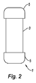
図1と図2は、例えば、自動車エンジンを冷却するための熱交換器1を示す。この熱交換器1は、冷却液を循環させるための、細長いチューブ3を備えている。これらのチューブ3は、密集して配置されている。チューブ3は、1つ以上の列若しくは層として構成されている。図2は、1列のチューブ3よりなる熱交換器1を示している。 1 and 2 show, for example, a heat exchanger 1 for cooling an automobile engine. The heat exchanger 1 includes an elongated tube 3 for circulating a coolant. These tubes 3 are densely arranged. The tube 3 is configured as one or more rows or layers. FIG. 2 shows a heat exchanger 1 consisting of a row of tubes 3.
各チューブ3の各端部は、対応する集合タンク5に接続されている。従って、熱交換器1は、互いに連通するチューブ3を備える上下2個の同類の集合タンク5を備えている。集合タンク5は、平行六面体の形状で、上下に対向している。
Each end of each tube 3 is connected to a
2本の隣接するチューブ3の間には、波形状の熱交換フィン7が設けられ、その波形の各頂部は、隣接する2本のチューブ3に接触している。 Between two adjacent tubes 3, wave-shaped heat exchange fins 7 are provided, and the tops of the corrugations are in contact with the two adjacent tubes 3.
作動時に、チューブ3内を循環する冷却流体と、通常は空気である外部の流体との間で、熱交換が行われる。 In operation, heat exchange takes place between the cooling fluid circulating in the tube 3 and an external fluid, usually air.
図3は、1個の集合タンク(図示せず)におけるマニホールド9として形成されたプレートを示している。このマニホールドとカバー(この図には示さず)により、集合タンク5が形成されている。この実施例においては、カバーは、平行六面体よりなり、マニホールドは、1つの平面に延びる、四角形体である。
FIG. 3 shows a plate formed as a manifold 9 in one collecting tank (not shown). The manifold and the cover (not shown in this figure) form a
マニホールド9は、中心部10と、これを囲む周縁部11とを備えている。中心部10には、チューブ3の端部を、挿入するのに好適な形状と位置に、貫通孔12が設けられている。
The manifold 9 includes a center portion 10 and a peripheral edge portion 11 surrounding the center portion 10. A through
周縁部11には、シール4を収容するのに好適な周溝13が設けられている。シール4は、カバーと、マニホールド9をシールしている。マニホールド9の周壁15は、その中心部10に対し、ほぼ直角方向を向いている。周壁15は、カバーの横壁に接し、かつマニホールド9にかしめられるようになっている。
The peripheral edge 11 is provided with a
互いに平行な2個の平面、即ちマニホールド9の延長面の間に、中心部10が設けられている。これらの2個の平面とは、集合タンク5の内側に向かって曲がった第1面、即ちマニホールドの内側面16と、集合タンク5の外側に曲がった第2面、即ちマニホールドの外側面17である。
A central portion 10 is provided between two parallel planes, that is, between the extended surfaces of the manifold 9. These two planes are the first surface bent toward the inside of the
本発明によれば、貫通孔12に挿入されたチューブ3の内端部は、内側面16とほぼ一致するか、それよりもわずかに短くなっている。
According to the present invention, the inner end portion of the tube 3 inserted into the through
図4〜図6は、貫通孔12を有するマニホールド9の部分、即ち図3における部分IVを、詳細に示している。
4 to 6 show in detail the portion of the manifold 9 with the through
マニホールド9は、貫通孔12を囲む内側突出部(「カラー」ともよぶ)19を形成する部分を有している。カラー19は、マニホールド9の延長面とほぼ直交し、外側面17から内側面16の方向に、マニホールド9の内面から突出している。カラー19の遊端は、内側面16から後退している。カラー19は、プレートの裏打ち材を押し出すことにより作られ、貫通孔12の断面をわずかに狭めることにより、マニホールド9の外面に形成されている。
The manifold 9 has a portion that forms an inner protrusion ( also referred to as “ color ”) 19 surrounding the through
カラー19と、隣のチューブの通路に対応する接続部21は連結されている。接続部21は、延長面と直交し、内側面16より外側面17に延びる方向に突出している。この接続部21は、延長面の下側に位置している。
The
換言すると、各貫通孔12の近傍において、マニホールド9は、チューブ3の端部のための受止部を備え、チューブ3を保持すべく、内側に突出する部分と、この内側突出部をマニホールドと連結する接続部とを備え、この接続部は、集合タンクと対向して、マニホールド9の側部に突出し、これら内側突出部と接続部は、互いに反対方向に突出している。
In other words, in the vicinity of each through-
この実施例においては、貫通孔12は、平坦なチューブの通路となっている。すなわち、この通路の断面は、互いに平行な2本の平面と、これらを結合する半円とよりなっている。カラー19は、長円形の貫通孔12に準じる形となっている。
In this embodiment, the through
この実施例において、接続部21は、貫通孔12の長さ方向を向く細長いボスのように、マニホールド9を形成することにより作られている。ボスの断面は、波形である。この波形は、チューブの全方向に延びている。特に、複数列の管である時に、長手方向に配置されたいくつかのカラー19のために、ただ1つの接続部21とすることが可能である。
In this embodiment, the connecting
チューブを、より容易に挿入しうるベンドにより、カラー19の基部は、各接続部23の基板に取り付けられている。
The base portion of the
各カラー19は、貫通孔12を囲む突環となっている。
Each
図4〜図6に示すように、マニホールドは、接続部とよく似た構成であり、管通孔の横方向に互いに連結された波形状である。即ち、接続部21も互いに連結されている。波形の頂部は、内側面16と外側面17を交互に有している。貫通孔12の延長面は、外側面17に含まれる頂部の線と一致している。
As shown in FIGS. 4 to 6, the manifold has a configuration that is very similar to the connection portion, and has a wave shape that is connected to each other in the lateral direction of the tube passage hole. That is, the connecting
図6に示すように、接続部23は、接続部23同士を連結するとともに、集合タンク( 「回収プレート」ともよぶ)の残りの部分に接続される基部50を備えている。
As shown in FIG. 6, the
図7は、シールを収容するための周溝13を備える、マニホールド9内の管の通路のための貫通孔12を示している。
FIG. 7 shows a through-
図8は、スロット13を設けていない、マニホールドの例を示し、チューブ3(図示せず)とマニホールドの周壁15との間に、シールが設けられている。
FIG. 8 shows an example of a manifold in which no
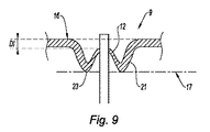
図9と図10は、本発明の別の実施例を示し、集合タンクと対向する面の側部に、カラー19の遊端を、内側面16から2 mmの距離D1のように出来る限り近付けたものである。これにより、チューブ3を有することが可能になり、図9のように、集合タンク5の内部の方向へ、向けられた内側面の側部において、マニホールド9の内側面から、端部が、最大で2 mm突出しているか、図10のように、内側面の管の端部に位置することが可能となっている。
FIGS. 9 and 10 show another embodiment of the present invention, in which the free end of the
図11〜図13は、チューブ3の端部を支える部分の製造法を示している。
第1の段階において、図11に示すように、金属プレートの部分は、ボス27のように形成される。プレートの大きな面になされる、少なくとも1回の押圧操作により、反対方向に突出するように、マニホールドの内面を形成し、更にマニホールドの外面を形成する。このようにしてマニホールドを変形させると、ボス27を形成するプレートの部分の厚さを一定にすることができる。
11 to 13 show a method for manufacturing a portion that supports the end of the tube 3.
In the first stage, as shown in FIG. 11, a portion of the metal plate is formed like a
第2段階において、図12に示すように、ボス27の隆起の方向とは反対方向に隆起するボス29を形成する。これは、外面から内面に向かって行われる少なくとも1回の押圧操作によるものである。
In the second stage, as shown in FIG. 12, a
第3段階において、図13に示すように、マニホールド9のプレートの外面から、ボス29の頂部を貫通する貫通孔12を形成する。この操作により、マニホールドを薄くして、ボス29を延ばし、カラー19が形成される。
In the third stage, as shown in FIG. 13, a through
本発明は、上記の実施例に限定されるものではなく、当業者による幾多の変形例が可能である。特に、チューブ3の断面を、上記の実施例と異なるものとしても良く、例えば、「豆型」、「四角形」若しくは他の形状でもよい。チューブの層の数は変更可能である。保持部は、内側包装面を超え、内側に僅かに突出していてもよい。 The present invention is not limited to the above-described embodiments, and many variations by those skilled in the art are possible. In particular, the cross section of the tube 3 may be different from that of the above embodiment, and may be, for example, “bean-shaped”, “square”, or other shapes. The number of tube layers can be varied. The holding part may protrude slightly inward beyond the inner packaging surface.
1 熱交換器
3 チューブ
4 シール
5 集合タンク
7 熱交換フィン
9 マニホールド
10 中心部
11 周縁部
12 貫通孔
13 周溝
14 シール
15 周壁
16 内側面
17 外側面
19 カラー
21,23 接続部
27,29 ボス
50 基部
1 Heat Exchanger 3 Tube 4
10 Center
11 Perimeter
12 Through hole
13 Circumferential groove
14 Seal
15 perimeter wall
16 Inner side
17 Outside
19 colors
21,23 connections
27,29 boss
50 base
Claims (15)
前記受止部は、前記内側突出部(19)を、前記マニホールド(9)の前記保持部以外の部分に連結する接続部(21)を備え、この接続部(21)は、前記集合タンク(5)と対向する前記マニホールド(9)の側部において突出しており、それにより、前記内側突出部(19)及び前記接続部(21)が、互いに反対方向に突出しており、
前記チューブ(3)の端面が、前記集合タンク(5)の内側に面している前記マニホールド(9)の内側面(16)にほぼ一致する位置に配置されているか、前記マニホールド (9)の内側面(16)に到達しない位置に離隔して配置されていることを特徴とする熱交換器。 Circulating cooling fluidforAt least one elongated tube (3);thisEnd of tube (3)Is connectedThe fluidFor distributionWith at least one collecting tank (5)A heat exchanger,SaidThe collecting tank (5) is the tube(3 )With a manifold (9) having a receiving part for the end of theAndThis receiving part isSaidtube(3)offorHolding partTheFormationDoInward protrusionPart(19)HaveIn the heat exchanger
The receiving part isSaidInward protrusionPart (19)TheSaidManifold(9)ofOther than the holding partThe connecting portion (21) connected to the portion of the connecting portion (21),SaidCollecting tank(5)OppositeSaidManifold(9)Protruding at the side ofAnd,Thereby,SaidInward protrusionPart(19) andSaidThe connecting parts (21) protrude in opposite directionsAnd,
Saidtube(3)End ofsurfaceBut,SaidCollecting tank(5)ofSaid inward facingManifold(9)Inside surface(16)InAlmost matchDoPlaced in positionOrSaidManifold (9)Inside surface(16) It is arranged away from the position that does not reachA heat exchanger characterized by that.
Applications Claiming Priority (3)
| Application Number | Priority Date | Filing Date | Title |
|---|---|---|---|
| FR1052447A FR2958385B1 (en) | 2010-03-31 | 2010-03-31 | HEAT EXCHANGER WITH INCREASED PERFORMANCE |
| FR1052447 | 2010-03-31 | ||
| PCT/EP2011/054843 WO2011120977A2 (en) | 2010-03-31 | 2011-03-29 | Heat exchanger having enhanced performance |
Publications (3)
| Publication Number | Publication Date |
|---|---|
| JP2013524145A JP2013524145A (en) | 2013-06-17 |
| JP2013524145A5 JP2013524145A5 (en) | 2014-05-15 |
| JP5952259B2 true JP5952259B2 (en) | 2016-07-13 |
Family
ID=43242120
Family Applications (1)
| Application Number | Title | Priority Date | Filing Date |
|---|---|---|---|
| JP2013501809A Active JP5952259B2 (en) | 2010-03-31 | 2011-03-29 | Heat exchanger |
Country Status (8)
| Country | Link |
|---|---|
| US (1) | US9366487B2 (en) |
| EP (1) | EP2553376B1 (en) |
| JP (1) | JP5952259B2 (en) |
| KR (1) | KR20130022405A (en) |
| CN (1) | CN102933930B (en) |
| FR (1) | FR2958385B1 (en) |
| PL (1) | PL2553376T3 (en) |
| WO (1) | WO2011120977A2 (en) |
Families Citing this family (11)
| Publication number | Priority date | Publication date | Assignee | Title |
|---|---|---|---|---|
| DE102013208424A1 (en) * | 2013-05-07 | 2014-11-13 | Behr Gmbh & Co. Kg | Floor for a heat exchanger, in particular for a motor vehicle and method for producing the floor |
| FR3015016B1 (en) * | 2013-12-13 | 2019-05-17 | Valeo Systemes Thermiques | COLLECTOR BOX AND THERMAL EXCHANGER CORRESPONDING |
| DE102014213758A1 (en) * | 2014-07-15 | 2016-01-21 | Mahle International Gmbh | Tube bottom and heat exchanger |
| JP6583071B2 (en) * | 2015-03-20 | 2019-10-02 | 株式会社デンソー | Tank and heat exchanger |
| DE102015209130A1 (en) * | 2015-05-19 | 2016-11-24 | Mahle International Gmbh | Heat exchanger |
| FR3036469B1 (en) * | 2015-05-22 | 2017-06-09 | Valeo Systemes Thermiques | COLLECTOR PLATE FOR HEAT EXCHANGER, IN PARTICULAR FOR MOTOR VEHICLE |
| FR3037643B1 (en) * | 2015-06-22 | 2019-07-12 | Valeo Systemes Thermiques | HEAT EXCHANGER AND METHOD FOR MANUFACTURING THE SAME |
| US10378834B2 (en) * | 2015-07-07 | 2019-08-13 | Mahle International Gmbh | Tube header for heat exchanger |
| US20170045309A1 (en) * | 2015-08-11 | 2017-02-16 | Hamilton Sundstrand Corporation | High temperature flow manifold |
| DE102020202962A1 (en) * | 2020-03-09 | 2021-09-09 | Hanon Systems | Collectors of a heat exchanger for a vehicle and such heat exchangers |
| LU101721B1 (en) * | 2020-03-31 | 2021-09-30 | Ht Holding Luxembourg S A | Heat exchanger |
Family Cites Families (23)
| Publication number | Priority date | Publication date | Assignee | Title |
|---|---|---|---|---|
| US4159741A (en) * | 1974-10-25 | 1979-07-03 | Suddeutsche Kuhlerfabrik Julius Fr. Behr | Heat exchanger |
| JPS5656595A (en) * | 1979-10-12 | 1981-05-18 | Nippon Denso Co Ltd | Heat exchanger |
| FR2538526B1 (en) * | 1982-12-22 | 1986-12-19 | Chausson Usines Sa | COLLECTOR PLATE FOR TUBE AND WATER BOX HEAT EXCHANGER |
| DE3673780D1 (en) * | 1985-12-16 | 1990-10-04 | Akzo Nv | CONNECTING HOLLOW PROFILE BODIES TO A PLASTIC PLATE, ESPECIALLY FOR THE PRODUCTION OF HEAT EXCHANGERS. |
| JPS63159683U (en) * | 1987-04-08 | 1988-10-19 | ||
| US5327959A (en) * | 1992-09-18 | 1994-07-12 | Modine Manufacturing Company | Header for an evaporator |
| FR2739680B1 (en) * | 1995-10-06 | 1997-12-05 | Valeo Thermique Moteur Sa | HEAT EXCHANGER, PARTICULARLY SUPPLY AIR RADIATOR FOR MOTOR VEHICLE |
| JP3414171B2 (en) * | 1996-11-29 | 2003-06-09 | 株式会社デンソー | Heat exchanger |
| FR2783903A1 (en) | 1998-09-30 | 2000-03-31 | Claude Rey | Electric water heater with controlled and natural circulation for more efficient and more uniform water heating |
| DE19844848A1 (en) | 1998-09-30 | 2000-04-06 | Modine Mfg Co | Heat exchanger |
| JP2001336885A (en) * | 2000-05-29 | 2001-12-07 | Mitsubishi Heavy Ind Ltd | Heat exchanger |
| US6554929B2 (en) * | 2001-01-11 | 2003-04-29 | Lg Electronics Inc. | Method for joining tube headers and header tanks of plastic heat exchanger |
| JP3483538B2 (en) * | 2001-03-13 | 2004-01-06 | 株式会社日本クライメイトシステムズ | Heat exchanger |
| JP4107051B2 (en) * | 2002-02-19 | 2008-06-25 | 株式会社デンソー | Heat exchanger |
| DE10234272A1 (en) | 2002-07-27 | 2004-02-05 | Modine Manufacturing Co., Racine | Heat exchangers and manufacturing processes |
| DE10247837A1 (en) * | 2002-10-14 | 2004-04-22 | Behr Gmbh & Co. | Automotive exhaust assembly heat exchanger has fluid-filled pipes linked by a funnel-shaped head piece and surrounded by a supplementary jacket |
| JP2004219044A (en) * | 2002-12-26 | 2004-08-05 | Denso Corp | Manufacturing method of heat exchanger and core plate |
| DE10315371A1 (en) * | 2003-04-03 | 2004-10-14 | Behr Gmbh & Co. Kg | Heat exchanger |
| JP2006284107A (en) * | 2005-04-01 | 2006-10-19 | Denso Corp | Heat exchanger |
| JP2007170747A (en) * | 2005-12-22 | 2007-07-05 | Denso Corp | Heat exchanger |
| DE102006045200A1 (en) * | 2006-09-25 | 2008-04-10 | Denso Corp., Kariya | Heat exchanger for use as radiator of water-cooled combustion engine, has connecting part including admitting section outside of ends of ribs, where admitting section allows deformation of connecting part in longitudinal direction |
| WO2009008172A1 (en) * | 2007-07-11 | 2009-01-15 | Denso Corporation | Heat exchanger |
| ES2711572T3 (en) * | 2010-03-31 | 2019-05-06 | Modine Mfg Co | Heat exchanger |
-
2010
- 2010-03-31 FR FR1052447A patent/FR2958385B1/en active Active
-
2011
- 2011-03-29 US US13/637,635 patent/US9366487B2/en active Active
- 2011-03-29 JP JP2013501809A patent/JP5952259B2/en active Active
- 2011-03-29 PL PL11711331T patent/PL2553376T3/en unknown
- 2011-03-29 EP EP11711331.6A patent/EP2553376B1/en active Active
- 2011-03-29 WO PCT/EP2011/054843 patent/WO2011120977A2/en active Application Filing
- 2011-03-29 CN CN201180027106.5A patent/CN102933930B/en active Active
- 2011-03-29 KR KR1020127028494A patent/KR20130022405A/en not_active Application Discontinuation
Also Published As
| Publication number | Publication date |
|---|---|
| FR2958385A1 (en) | 2011-10-07 |
| WO2011120977A3 (en) | 2012-02-02 |
| CN102933930A (en) | 2013-02-13 |
| EP2553376B1 (en) | 2014-02-12 |
| KR20130022405A (en) | 2013-03-06 |
| PL2553376T3 (en) | 2014-10-31 |
| WO2011120977A2 (en) | 2011-10-06 |
| CN102933930B (en) | 2016-08-24 |
| EP2553376A2 (en) | 2013-02-06 |
| FR2958385B1 (en) | 2013-01-18 |
| JP2013524145A (en) | 2013-06-17 |
| US20130160973A1 (en) | 2013-06-27 |
| US9366487B2 (en) | 2016-06-14 |
Similar Documents
| Publication | Publication Date | Title |
|---|---|---|
| JP5952259B2 (en) | Heat exchanger | |
| US6786275B2 (en) | Heat exchanger header assembly | |
| US20150300745A1 (en) | Counterflow helical heat exchanger | |
| JP5688355B2 (en) | Flat plate of header plateless heat exchanger | |
| JP5029166B2 (en) | Heat exchanger | |
| JP2008527305A (en) | Heat exchangers, especially supply air coolers or refrigerant coolers for automobiles | |
| JP5945806B2 (en) | Finned tube heat exchanger | |
| US10113801B2 (en) | Multi-fluid heat exchanger arrangement | |
| JP5335568B2 (en) | Flat tube heat exchanger | |
| JP2014169851A (en) | Heat exchanger | |
| EP4006477A1 (en) | Plate heat exchanger | |
| US20070267185A1 (en) | Header for high pressure heat exchanger | |
| JP5953323B2 (en) | Heat exchanger | |
| JP6837397B2 (en) | Heat exchanger manufacturing method and multi-row heat exchanger | |
| CN109595951B (en) | Heat exchange device | |
| JP5226342B2 (en) | Cold storage / heat storage type heat exchanger | |
| JP5958917B2 (en) | Finned tube heat exchanger | |
| JP2009150587A (en) | Heat exchanger | |
| CN111141163B (en) | Welded plate heat exchanger | |
| JP7091308B2 (en) | Delon cup type heat exchanger | |
| JP5869267B2 (en) | Manufacturing method of liquid cooling heat sink | |
| JPWO2020004292A1 (en) | Heat exchanger tank structure | |
| US20130048261A1 (en) | Heat exhanger | |
| CN105890399A (en) | Heat exchanger | |
| JP4341490B2 (en) | Heat exchanger |
Legal Events
| Date | Code | Title | Description |
|---|---|---|---|
| A521 | Request for written amendment filed |
Free format text: JAPANESE INTERMEDIATE CODE: A523 Effective date: 20140327 |
|
| A621 | Written request for application examination |
Free format text: JAPANESE INTERMEDIATE CODE: A621 Effective date: 20140327 |
|
| A977 | Report on retrieval |
Free format text: JAPANESE INTERMEDIATE CODE: A971007 Effective date: 20150205 |
|
| A131 | Notification of reasons for refusal |
Free format text: JAPANESE INTERMEDIATE CODE: A131 Effective date: 20150310 |
|
| A601 | Written request for extension of time |
Free format text: JAPANESE INTERMEDIATE CODE: A601 Effective date: 20150602 |
|
| A521 | Request for written amendment filed |
Free format text: JAPANESE INTERMEDIATE CODE: A523 Effective date: 20150710 |
|
| A131 | Notification of reasons for refusal |
Free format text: JAPANESE INTERMEDIATE CODE: A131 Effective date: 20150811 |
|
| A521 | Request for written amendment filed |
Free format text: JAPANESE INTERMEDIATE CODE: A523 Effective date: 20151111 |
|
| A521 | Request for written amendment filed |
Free format text: JAPANESE INTERMEDIATE CODE: A523 Effective date: 20151111 |
|
| TRDD | Decision of grant or rejection written | ||
| A01 | Written decision to grant a patent or to grant a registration (utility model) |
Free format text: JAPANESE INTERMEDIATE CODE: A01 Effective date: 20160510 |
|
| A61 | First payment of annual fees (during grant procedure) |
Free format text: JAPANESE INTERMEDIATE CODE: A61 Effective date: 20160609 |
|
| R150 | Certificate of patent or registration of utility model |
Ref document number: 5952259 Country of ref document: JP Free format text: JAPANESE INTERMEDIATE CODE: R150 |
|
| R250 | Receipt of annual fees |
Free format text: JAPANESE INTERMEDIATE CODE: R250 |
|
| R250 | Receipt of annual fees |
Free format text: JAPANESE INTERMEDIATE CODE: R250 |
|
| R250 | Receipt of annual fees |
Free format text: JAPANESE INTERMEDIATE CODE: R250 |
|
| R250 | Receipt of annual fees |
Free format text: JAPANESE INTERMEDIATE CODE: R250 |
|
| R250 | Receipt of annual fees |
Free format text: JAPANESE INTERMEDIATE CODE: R250 |