WO2017065271A1 - 同期装置 - Google Patents
同期装置 Download PDFInfo
- Publication number
- WO2017065271A1 WO2017065271A1 PCT/JP2016/080528 JP2016080528W WO2017065271A1 WO 2017065271 A1 WO2017065271 A1 WO 2017065271A1 JP 2016080528 W JP2016080528 W JP 2016080528W WO 2017065271 A1 WO2017065271 A1 WO 2017065271A1
- Authority
- WO
- WIPO (PCT)
- Prior art keywords
- ring
- hub
- gear
- inner ring
- sleeve
- Prior art date
- Legal status (The legal status is an assumption and is not a legal conclusion. Google has not performed a legal analysis and makes no representation as to the accuracy of the status listed.)
- Ceased
Links
Images


Classifications
-
- F—MECHANICAL ENGINEERING; LIGHTING; HEATING; WEAPONS; BLASTING
- F16—ENGINEERING ELEMENTS AND UNITS; GENERAL MEASURES FOR PRODUCING AND MAINTAINING EFFECTIVE FUNCTIONING OF MACHINES OR INSTALLATIONS; THERMAL INSULATION IN GENERAL
- F16D—COUPLINGS FOR TRANSMITTING ROTATION; CLUTCHES; BRAKES
- F16D23/00—Details of mechanically-actuated clutches not specific for one distinct type
- F16D23/02—Arrangements for synchronisation, also for power-operated clutches
- F16D23/04—Arrangements for synchronisation, also for power-operated clutches with an additional friction clutch
- F16D23/06—Arrangements for synchronisation, also for power-operated clutches with an additional friction clutch and a blocking mechanism preventing the engagement of the main clutch prior to synchronisation
Definitions
- the present disclosure relates to a synchronization device for synchronizing a shaft with a member (a coupling target member) such as a transmission gear to be coupled to a shaft when a gear position or a transmission range is switched.
- a member a coupling target member
- a gear position is switched by switching a transmission gear coupled to a shaft.
- the transmission includes a sub-transmission composed of, for example, a planetary gear mechanism having a sun gear, a pinion gear, a ring gear, and the like, and a dog plate fixed to the transmission case is coupled to the ring gear of the sub-transmission. By doing so, the shift range is switched.
- a sub-transmission composed of, for example, a planetary gear mechanism having a sun gear, a pinion gear, a ring gear, and the like, and a dog plate fixed to the transmission case is coupled to the ring gear of the sub-transmission.
- a synchronizer ring is provided between a hub and a sleeve that are coupled to a shaft and a coupling target member such as a transmission gear or a dog plate that is a coupling target to facilitate synchronization.
- a coupling target member such as a transmission gear or a dog plate that is a coupling target to facilitate synchronization.
- the synchronizer ring includes, for example, an outer ring having synchro teeth, an inner ring arranged on the inner side in the radial direction of the outer ring, and a cone ring arranged between the outer ring and the inner ring.
- the end on the hub side of the outer ring is provided with a convex portion protruding radially inward, while the concave portion for engaging the convex portion on the hub side end of the inner ring.
- the outer ring and the inner ring are connected so as not to rotate relative to each other.
- Patent Document 1 discloses a technique for performing smooth synchronization in a transmission having such a synchronizer ring.
- the outer ring convex portion and the inner ring concave portion are engaged with each other so as to be relatively unrotatable, but the outer ring convex portion and the inner ring concave portion are connected to each other. If the position in the axial direction is deviated, there is a possibility that the convex part of the outer ring rides over the concave part of the inner ring and rides on another part of the inner ring. Thus, when the convex part of the outer ring gets over the concave part of the inner ring, the frictional force for synchronization by the synchronizer ring is not generated, and the dog gears try to mesh with each other in an unsynchronized state. Gear squeal).
- the present disclosure has been made in view of the above problems, and an object of the present disclosure is to provide a technique that can appropriately reduce the protrusion of the outer ring over the recess of the inner ring.
- a synchronization device includes a hub fixed to a rotation shaft, a sleeve that is not rotatable relative to the hub and is movable in an axial direction, and a sleeve.
- a synchronizer having a coupling target member to be coupled with the rotation shaft, a sleeve and a synchronizer ring that is interposed between the coupling target member and the hub, and synchronizes the coupling target member
- the synchronizer ring is composed of an outer ring in which teeth that can be combined with the teeth of the sleeve are formed on the outer periphery, an inner ring that is disposed radially inside the outer ring, and a cone ring that is disposed between the outer ring and the inner ring.
- the outer ring is located on the hub side with respect to a part of the inner ring, and has a convex part that protrudes radially inward from a part of the inner ring.
- the inner ring is recessed on the hub side end surface and has a recessed portion that can be engaged with the protruding portion, and the outer ring is formed at a portion facing the circumferential end surface of the recessed portion on both sides in the circumferential direction of the protruding portion. And an engagement maintaining portion formed to extend toward the coupling target member side.
- the member to be coupled may be fixed to the case housing the synchronization device so as not to rotate.
- the member to be coupled may be a dog plate in which dog teeth that can be coupled to the teeth of the sleeve are formed.
- the length of the engagement maintaining portion in the axial direction is when the distance between the hub and the member to be coupled is the largest and the axial displacement between the outer ring and the inner ring is the largest. Even if it exists, you may form so that the position by the side of the connection object member of an engagement maintenance part may become a connection object member side rather than the position by the side of the hub of the recessed part of an inner ring.
- FIG. 1 shows an overview of a mechanical automatic manual transmission having a synchronization device according to an embodiment of the present disclosure.
- FIG. 2 is a perspective view of a synchronizer ring according to an embodiment of the present disclosure.
- FIG. 3A is a front view of the synchronizer ring according to an embodiment of the present disclosure as viewed from an arrow Y in FIG. 2.
- FIG. 3B is a cross-sectional view taken along line XX of FIG. 2 of the synchronizer ring according to an embodiment of the present disclosure.
- FIG. 1 shows an outline of a mechanical automatic manual transmission having a synchronization device according to an embodiment of the present disclosure.
- a mechanical automatic manual transmission (referred to as a transmission) 1 includes an input shaft 10, a main shaft 11 that is disposed coaxially with the input shaft 10, and a shaft that is disposed coaxially with the main shaft 11 on the output side of the main shaft 11.
- the auxiliary transmission 60 includes a counter shaft 12 and a reverse idler shaft 16 that are arranged in parallel with the input shaft 10 and the main shaft 11.
- the input main gear 13 is provided on the input shaft 10 so as to be integrally rotatable.
- the main shaft 11 includes, in order from the input side, a first hub 21, a 5th / 9th speed main gear M5, a 3rd / 7th speed main gear M3, a second hub 31, a 2nd / 6th speed main gear M2, a first speed main gear M1, A third hub 41, a reverse main gear MR, a guide piece 53, and a sun gear 61 of the auxiliary transmission 60 are provided.
- the 5-speed / 9-speed main gear M5, 3-speed / 7-speed main gear M3, 2-speed / 6-speed main gear M2, 1-speed main gear M1, and reverse main gear MR are provided on the main shaft 11 so as to be relatively rotatable.
- the second hub 31, the third hub 41, the guide piece 53, and the sun gear 61 are provided on the main shaft 11 so as to be integrally rotatable.
- the auxiliary transmission 60 transmits the rotation to the carrier 63 (output shaft) by switching the rotation of the main shaft 11 between two ranges of high (high speed) and low (low speed).
- the auxiliary transmission 60 is configured by, for example, a planetary gear mechanism.
- the auxiliary transmission 60 includes a sun gear 61, a plurality of planetary gears 62 disposed around the sun gear 61 so as to mesh with the sun gear 61, and a ring gear 64 formed with internal teeth that mesh with the planetary gear 62.
- a carrier 63 that rotatably supports the plurality of planetary gears 62.
- the output side of the carrier 63 has a cylindrical shape coaxial with the main shaft 11.
- annular portion (rotating shaft) 65 that surrounds a cylindrical portion of the carrier 63 and is rotatable relative to the carrier 63 is formed.
- a fourth hub 66 is provided in the annular portion 65 so as to be integrally rotatable.
- a dog gear 63a is fixed on the rear side of the carrier 63 with respect to the fourth hub 66.
- the main shaft 11 Inside the main shaft 11, it extends in the axial direction and extends in the axial direction to the outer peripheral surface of the main shaft 11 from the axial flow channel 11 a to flow the lubricating oil.
- One or more radial flow paths 11b for discharging from the opening (exit) are formed.
- the radial flow path 11b is formed in each of the fifth speed / 9th speed main gear M5, the third speed / 7th speed main gear M3, the second speed / 6th speed main gear M2, the first speed main gear M1, the reverse main gear MR, and the guide piece 53. It is provided at a position facing the peripheral surface.
- the counter shaft 12 meshes with the input counter gear 14 meshed with the input main gear 13 and the 5th / 9th counter gear C5 and 3rd / 7th main gear M3 meshed with the 5th / 9th main gear M5 in order from the input side.
- a reverse counter gear CR that meshes with the idler gear 17 is provided.
- the input counter gear 14, the 5th / 9th counter gear C5, the 3rd / 7th counter gear C3, the 2nd / 6th counter gear C2, the 1st speed counter gear C1, and the reverse counter gear CR are integrated with the counter shaft 12. It is provided so as to be rotatable. On the output side of the countershaft 12, a countershaft brake 15 for braking the rotation of the countershaft 12 is provided.
- An idler gear 17 is provided on the reverse idler shaft 16 so as to be relatively rotatable.
- the idler gear 17 meshes with the reverse counter gear CR and the reverse main gear MR.
- a first sleeve 22 is attached to the first hub 21 so that it cannot rotate but can move in the axial direction.
- a synchronizer ring may be interposed between the first sleeve 22 and each of the input main gear 13 and a dog gear (not shown) fixed to each of the fifth speed / 9th speed main gear M5.
- a shift fork (not shown) that moves the first sleeve 22 in the axial direction is engaged with the outer circumferential groove of the first sleeve 22.
- a second sleeve 32 is attached to the second hub 31 so as not to rotate but to move in the axial direction.
- a synchronizer ring may be interposed between the second sleeve 32 and a dog gear (not shown) fixed to each of the third speed / 7th speed main gear M3 and the second speed / 6th speed main gear M2.
- a shift fork (not shown) that moves the second sleeve 32 in the axial direction is engaged with the outer circumferential concave groove of the second sleeve 32.
- a third sleeve 42 is attached to the third hub 41 so as not to rotate but to move in the axial direction.
- a synchronizer ring may be interposed between the third sleeve 42 and a dog gear (not shown) fixed to each of the first speed main gear M1 and the reverse main gear MR.
- a shift fork (not shown) that moves the third sleeve 42 in the axial direction is engaged with the outer circumferential concave groove of the third sleeve 42.
- the third sleeve 42 moves in the direction of arrow A in the drawing and is spline-engaged with the dog gear connected to the first-speed main gear M1, the input main gear 13, the input counter gear 14, the first-speed counter gear C1, and the first-speed main gear M1 are passed through.
- power is transmitted to the main shaft 11.
- the range of the sub-transmission 60 is fixedly set to one range (for example, the low range). Therefore, the carrier 63 rotates at the first speed.
- the third sleeve 42 moves in the direction of arrow B in the figure and is spline-engaged with the dog gear connected to the reverse main gear MR, the input main gear 13, the input counter gear 14, the reverse counter gear CR, the idler gear 17, and the reverse main gear MR are passed through.
- power is transmitted to the main shaft 11.
- the range of the sub-transmission 60 is fixedly set to one range (for example, the low range).
- the carrier 63 rotates in the reverse direction.
- a fourth sleeve 67 is attached to the fourth hub 66 so as not to rotate but to move in the axial direction.
- a synchronizer ring SR is interposed between the fourth sleeve 67 and each of the dog plate 71 (member to be coupled) and the dog gear 63 a fixed to the carrier 63.
- a shift fork (not shown) that moves the fourth sleeve 67 in the axial direction is engaged with the outer circumferential groove of the fourth sleeve 67.
- the synchronization device 90 includes a carrier 63, an annular portion 65, a fourth hub 66, a fourth sleeve 67, a dog plate 71, a dog gear 63a, and a synchronizer ring SR.
- the fourth sleeve 67 moves in the direction of arrow A in the drawing and engages with the dog teeth 71a of the dog plate 71 fixed to the transmission case 2 (for example, the center case 2b) by spline, the ring gear 64 is brought into the transmission case 2.
- the auxiliary transmission 60 is in the low range. That is, when the main shaft 11 is rotated by the auxiliary transmission 60, the carrier 63 is rotated at a reduction ratio greater than 1.
- the fourth sleeve 67 moves in the direction of arrow B in the drawing and meshes with the dog gear 63a fixed to the carrier 63 by spline, the ring gear 64 and the carrier 63 are fixed so as to rotate together, and the sub-shift is performed.
- the state of the machine 60 is in the high range. That is, the main shaft 11 and the carrier 63 are directly connected by the auxiliary transmission 60.
- the transmission case 2 front case 2 a, center case 2 b, rear case 2 c, etc. except for the input side end of the input shaft 10 and the output side end of the carrier 63. ).
- Lubricating oil for lubricating each part is supplied to the inside of the transmission case 2.
- an oil pipe 80 for sucking the lubricating oil stored in the bottom is disposed.
- the oil pipe 80 is connected to an oil pump (not shown), and the lubricating oil sucked through the oil pipe 80 is supplied to, for example, the axial flow path 11 a of the main shaft 11.
- FIG. 2 is a perspective view of a synchronizer ring according to an embodiment of the present disclosure.
- FIG. 2 shows a synchronizer ring SR interposed between the dog plate 71 and the fourth hub 66 in order to synchronize the dog plate 71 and the annular portion 65.
- the arrow A direction and the arrow B direction in FIG. 2 correspond to the respective directions shown in FIG.
- the synchronizer ring SR has an outer ring 91, a cone ring 92, and an inner ring 93.
- the outer ring 91 is a ring that is disposed on the outermost side in the radial direction (the radial direction of the annular portion 65), and the outer peripheral end of the dog plate 71 (arrow A direction side) is the inner periphery of the fourth sleeve 67. Synchronized teeth 91a that can be splined with spline teeth formed on the surface are formed.
- the outer ring 91 is located on the fourth hub 66 side (arrow B direction side) on the fourth hub 66 side with respect to a part of the inner ring 93 and protrudes radially inward from a part of the inner ring 93. It has a plurality (three in the figure) of convex portions 91b.
- the cone ring 92 is disposed between the outer ring 91 and the inner ring 93, and can contact the inner peripheral surface of the outer ring 91 and the outer peripheral surface of the inner ring 93. Friction resistance for synchronizing
- the inner ring 93 is a cylindrical ring disposed in the radial direction from the cone ring 92 and extending in the AB direction.
- a plurality (six in the figure) of recesses 93 a that are recessed in the direction of arrow A are formed on the arrow B direction side of the inner ring 93.
- the concave portion 93a engages with the convex portion 91b of the outer ring 91 to connect the outer ring 91 and the inner ring 93 so as not to be relatively rotatable.
- FIG. 3A is a front view of the synchronizer ring according to an embodiment of the present disclosure as viewed from an arrow Y in FIG. 2.
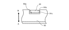
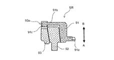
- FIG. 3B is a cross-sectional view taken along line XX of FIG. 2 of the synchronizer ring according to an embodiment of the present disclosure. 3B corresponds to a state in which the outer ring 91 is pushed toward the A direction side by the fourth sleeve 67, that is, a synchronized state.
- the front end (inner peripheral side) of the convex portion 91b of the outer ring 91 has an engagement maintaining portion 91c formed extending in the arrow A direction side.
- the engagement maintaining portion 91 c is provided at a position facing the circumferential surface (both surfaces) of the recess 93 a of the inner ring 93.
- the engagement maintaining portion 91c is formed to extend over the entire circumferential direction of the convex portion 91b.
- the recess 93a of the inner ring 93 has a rectangular shape when viewed from the direction of the arrow Y as shown in FIG. 3A.
- the convex part 91b and the engagement maintaining part 91c of the outer ring 91 combined with the concave part 93a of the inner ring 93 have a rectangular shape and are fitted into the space of the concave part 93a.
- the position of the engagement maintaining portion 91c on the A direction side is the recess 93a. Since the contact between the engagement maintaining portion 91c and the circumferential surface of the concave portion 93a is ensured if it exists on the A direction side of the position on the B direction side, the convex portion 91b of the outer ring 91 becomes the inner ring 93. It is possible to appropriately prevent the recesses 93a from getting over, and to maintain the outer ring 91 and the inner ring 93 in a state in which relative rotation is impossible.
- the synchronizer ring SR of FIG. 2 is interposed between the dog plate 71 and the fourth hub 66. Since the dog plate 71 is fixed to the transmission case 2, the displacement in the axial direction is small. On the other hand, since the fourth hub 66 is fixed to the annular portion 65 having a large movement in the axial direction, the displacement in the axial direction is large. Thereby, the space
- the axial length of the engagement maintaining portion 91c is the largest in the axial distance between the dog plate 71 and the fourth hub 66, and the shaft between the outer ring 91 and the inner ring 93 is the largest. Even when the direction deviation is the largest, the position of the engagement maintaining portion 91c on the A direction side is closer to the A direction side than the position of the concave portion 93a of the inner ring 93 on the B direction side. It is formed in such a length that at least a part of the circumferential surface of the engagement maintaining portion 91c and the circumferential surface of the recess 93a are in contact with each other. Note that the axial length of the engagement maintaining portion 91c is such that the side surface in the A direction of the engagement maintaining portion 91c does not contact the side surface in the A direction of the recess 93a of the inner ring 93 during synchronization.
- the engagement maintaining portion 91c formed to extend toward the dog plate 71 it is possible to reduce or prevent the convex portion 91b of the outer ring 91 from getting over the concave portion 93a of the inner ring 93. For this reason, generation
- the synchronization device that synchronizes the dog plate 71 and the annular portion 65 has been described.
- the present disclosure is not limited thereto, and the shaft (for example, the main shaft 11) and the transmission gear (member to be coupled)
- the present invention can also be applied to a synchronization device that synchronizes
- the present disclosure is not limited to this, and the length of the engagement maintaining portion 91c is not limited to this. May be shorter than the above-mentioned length, and even in this case, it is possible to reduce the fact that the convex portion 91b of the outer ring 91 gets over the concave portion 93a of the inner ring 93.
- the engagement maintenance part 91c was extended and formed in the whole circumferential direction of the convex part 91b, this indication is not restricted to this,
- the engagement maintenance part 91c is used for the convex part 91b. You may make it form separately in each of the part which opposes the circumferential direction end surface of the recessed part 93a of the circumferential direction both sides.
- the synchronization device of the present disclosure is useful in that it can appropriately reduce the protrusion of the outer ring over the recess of the inner ring.
Landscapes
- Engineering & Computer Science (AREA)
- General Engineering & Computer Science (AREA)
- Mechanical Engineering (AREA)
- Mechanical Operated Clutches (AREA)
Abstract
円環部65に固定された第4ハブ66と、第4スリーブ67と、ドグプレート71と、シンクロナイザリングSRと、を有する同期装置90において、シンクロナイザリングSRは、アウターリング91と、インナーリング93と、コーンリング92とを有し、アウターリング91は、インナーリング93の一部よりも第4ハブ66側に位置し、インナーリング93の一部よりも径方向内側まで突出する凸部91bを有し、インナーリング93は、第4ハブ66側端面に、ドグプレート71側に凹み、凸部91bと係合可能な凹部93aを有し、アウターリング91は、凸部91bの周方向両側の凹部93aの周方向の端面と対向する部分に、ドグプレート71側に延びて形成された係合維持部91cを有するように構成する。
Description
本開示は、変速段や、変速レンジを切り替える際に、シャフトに結合される対象となる変速ギヤ等の部材(結合対象部材)と、シャフトとの同期を行うための同期装置に関する。
従来、変速機においては、シャフトと結合する変速ギヤを切り替えることにより、変速段を切り替えている。
また、変速機においては、例えば、サンギヤ、ピニオンギヤ、リングギヤ等を有する遊星歯車機構によって構成されている副変速機を備え、変速機ケースに固定されているドグプレートと、副変速機のリングギヤとを結合することにより、変速のレンジを切り替えている。
例えば、変速機においては、シャフトに結合されているハブ及びスリーブと、結合対象となる変速ギヤやドグプレート等の結合対象部材との間に、同期を円滑にさせるためのシンクロナイザリングが設けられている。
シンクロナイザリングは、例えば、シンクロ歯を有するアウターリングと、アウターリングの径方向内側に配置されるインナーリングと、アウターリングとインナーリングに挟まれて配置されるコーンリングとで構成される。このようなシンクロナイザリングにおいては、アウターリングのハブ側の端部には、径方向内側に突出する凸部が設けられる一方、インナーリングのハブ側の端部に凸部と係合するための凹部が設けられ、アウターリングとインナーリングとが相対回転不能に連結されている。
このようなシンクロナイザリングを有する変速機において、スムーズに同期を行うための技術が、例えば、特許文献1に開示されている。
上述のようにシンクロナイザリングでは、アウターリングの凸部と、インナーリングの凹部とを係合させることにより、相対回転不能に連結しているが、アウターリングの凸部と、インナーリングの凹部との軸方向の位置がずれてしまうと、アウターリングの凸部がインナーリングの凹部を乗り越えて、インナーリングの別の部位に乗り上げてしまう事態が発生する可能性がある。このように、アウターリングの凸部がインナーリングの凹部を乗り越えてしまうと、シンクロナイザリングによる同期のための摩擦力が発生せず、同期しない状態でドグギヤ同士が噛み合おうとするため、異音(ギヤ鳴り)が発生してしまう。
このような事態は、変速機ケースに固定されているドグプレートと、副変速機のリングギヤに結合されているシャフトとの間に設けられているシンクロナイザリングにおいて、特に発生し易い。
本開示は、上記課題に鑑みなされたものであり、その目的は、アウターリングの凸部がインナーリングの凹部を乗り越えてしまうことを適切に低減することのできる技術を提供することにある。
上述の目的を達成するため、本開示の一観点に係る同期装置は、回転軸に固定されたハブと、ハブに対して相対回転不能且つ軸方向に移動可能に設けられたスリーブと、スリーブを介して、回転軸と結合させる対象の結合対象部材と、結合対象部材とハブとの間に介装され、スリーブと、結合対象部材とを同期させるシンクロナイザリングと、を有する同期装置であって、シンクロナイザリングは、スリーブの歯と結合可能な歯が外周に形成されたアウターリングと、アウターリングの径方向内側に配置されるインナーリングと、アウターリングとインナーリングとの間に配置されるコーンリングとを有し、アウターリングは、インナーリングの一部よりもハブ側に位置し、インナーリングの一部よりも径方向内側まで突出する凸部を有し、インナーリングは、ハブ側端面に、結合対象部材側に凹み、凸部と係合可能な凹部を有し、アウターリングは、凸部の周方向両側の凹部の周方向の端面と対向する部分に、結合対象部材側に延びて形成された係合維持部を有する。
上記同期装置において、結合対象部材は、同期装置を収容するケースに回転不能に固定されていてもよい。
また、上記同期装置において、結合対象部材は、スリーブの歯と結合可能なドグ歯が形成されたドグプレートであってもよい。
また、上記同期装置において、係合維持部の軸方向の長さは、ハブと結合対象部材との間隔が最も大きくなり、アウターリングとインナーリングとの軸方向のずれが最も大きくなった場合であっても、係合維持部の結合対象部材側の位置が、インナーリングの凹部のハブ側の位置よりも結合対象部材側となるように形成されていてもよい。
本開示によると、アウターリングの凸部がインナーリングの凹部を乗り越えてしまうことを適切に低減することができる。
以下、添付図面に基づいて、本開示の一実施形態に係る同期装置について説明する。同一の部品には同一の符号を付してあり、それらの名称および機能も同じである。したがって、それらについての詳細な説明は繰返さない。
図1は、本開示の一実施形態に係る同期装置を有する機械式自動マニュアル変速機の概要を示す。
機械式自動マニュアル変速機(変速機という。)1は、インプットシャフト10と、インプットシャフト10と同軸に配置されたメインシャフト11と、メインシャフト11の出力側にメインシャフト11と同軸に配置された副変速機60と、インプットシャフト10及びメインシャフト11と平行に配置されたカウンタシャフト12及びリバースアイドラシャフト16と、を備えている。
インプットシャフト10には、インプットメインギヤ13が一体回転可能に設けられている。メインシャフト11には、入力側から順に、第1ハブ21、5速/9速メインギヤM5、3速/7速メインギヤM3、第2ハブ31、2速/6速メインギヤM2、1速メインギヤM1、第3ハブ41、リバースメインギヤMR、ガイドピース53、副変速機60のサンギヤ61が設けられている。5速/9速メインギヤM5、3速/7速メインギヤM3、2速/6速メインギヤM2、1速メインギヤM1、及びリバースメインギヤMRは、メインシャフト11に相対回転可能に設けられ、第1ハブ21、第2ハブ31、第3ハブ41、ガイドピース53、及びサンギヤ61はメインシャフト11に一体回転可能に設けられている。
副変速機60は、メインシャフト11の回転をハイ(高速)と、ロー(低速)の2つのレンジの何れかに切り替えてキャリア63(アウトプットシャフト)に伝達する。副変速機60は、例えば、遊星歯車機構により構成される。具体的には、副変速機60は、サンギヤ61と、サンギヤ61と噛合するようにサンギヤ61の周囲に配置された複数のプラネタリギヤ62と、プラネタリギヤ62と噛合する内歯が形成されたリングギヤ64と、複数のプラネタリギヤ62を回転可能に支持するキャリア63とを有する。キャリア63の出力側は、メインシャフト11と同軸の円柱状形状となっている。リングギヤ64の出力側は、キャリア63の円柱状形状の部分を取り囲み、キャリア63と相対回転可能な円環部(回転軸)65が形成されている。円環部65には、第4ハブ66が一体回転可能に設けられている。キャリア63の第4ハブ66よりも後方側には、ドグギヤ63aが固定されている。
メインシャフト11の内部には、軸方向に延び、潤滑油を流すための軸方向流路11aと、軸方向流路11aからメインシャフト11の外周面に径方向に延び、潤滑油を外周面の開孔(出口)から放出するための1以上の径方向流路11bが形成されている。径方向流路11bは、例えば、5速/9速メインギヤM5、3速/7速メインギヤM3、2速/6速メインギヤM2、1速メインギヤM1、リバースメインギヤMR、及びガイドピース53のそれぞれの内周面に対向する位置に設けられている。
カウンタシャフト12には、入力側から順に、インプットメインギヤ13と噛合するインプットカウンタギヤ14、5速/9速メインギヤM5と噛合する5速/9速カウンタギヤC5、3速/7速メインギヤM3と噛合する3速/7速カウンタギヤC3、2速/6速メインギヤM2と噛合する2速/6速カウンタギヤC2、1速メインギヤM1と噛合する1速カウンタギヤC1、リバースメインギヤMRと噛合する後述するアイドラギヤ17と噛合するリバースカウンタギヤCRが設けられている。インプットカウンタギヤ14、5速/9速カウンタギヤC5、3速/7速カウンタギヤC3、2速/6速カウンタギヤC2、1速カウンタギヤC1、及びリバースカウンタギヤCRは、カウンタシャフト12に一体回転可能に設けられている。カウンタシャフト12の出力側には、カウンタシャフト12の回転を制動するためのカウンタシャフトブレーキ15が設けられている。
リバースアイドラシャフト16には、アイドラギヤ17が相対回転可能に設けられている。アイドラギヤ17は、リバースカウンタギヤCRと、リバースメインギヤMRと噛合している。
第1ハブ21には、回転不能且つ軸方向に移動可能に第1スリーブ22が取り付けられている。なお、第1スリーブ22と、インプットメインギヤ13及び5速/9速メインギヤM5のそれぞれに固定されている図示しないドグギヤとのそれぞれの間にシンクロナイザリングが介装されていてもよい。第1スリーブ22の外周凹溝には、第1スリーブ22を軸方向に移動させる図示しないシフトフォークが係合されている。
第1スリーブ22が図中矢印A方向に移動してインプットメインギヤ13のドグギヤとスプライン噛合すると、インプットシャフト10とメインシャフト11とが直結されて動力が伝達される。この結果、副変速機60のレンジがローに設定されている場合には、キャリア63は、4速相当で回転し、副変速機60のレンジがハイに設定されている場合には、キャリア63は、8速相当で回転する。
第1スリーブ22が図中矢印B方向に移動して5速/9速メインギヤM5に接続されているドグギヤとスプライン噛合すると、インプットメインギヤ13、インプットカウンタギヤ14、5速/9速カウンタギヤC5、5速/9速メインギヤM5、を介してメインシャフト11に動力が伝達される。この結果、副変速機60のレンジがローに設定されている場合には、キャリア63は、5速相当で回転し、副変速機60のレンジがハイに設定されている場合には、キャリア63は、9速相当で回転する。
第2ハブ31には、回転不能且つ軸方向に移動可能に第2スリーブ32が取り付けられている。なお、第2スリーブ32と、3速/7速メインギヤM3及び2速/6速メインギヤM2のそれぞれに固定されている図示しないドグギヤとのそれぞれの間にシンクロナイザリングが介装されていてもよい。第2スリーブ32の外周凹溝には、第2スリーブ32を軸方向に移動させる図示しないシフトフォークが係合されている。
第2スリーブ32が図中矢印A方向に移動して3速/7速メインギヤM3に接続されているドグギヤとスプライン噛合すると、インプットメインギヤ13、インプットカウンタギヤ14、3速/7速カウンタギヤC3、3速/7速メインギヤM3を介して動力がメインシャフト11に伝達される。この結果、副変速機60のレンジがローに設定されている場合には、キャリア63は、3速相当で回転し、副変速機60のレンジがハイに設定されている場合には、キャリア63は、7速相当で回転する。
第2スリーブ32が図中矢印B方向に移動して2速/6速メインギヤM2に接続されているドグギヤとスプライン噛合すると、インプットメインギヤ13、インプットカウンタギヤ14、2速/6速カウンタギヤC2、2速/6速メインギヤM2を介して、メインシャフト11に動力が伝達される。この結果、副変速機60のレンジがローに設定されている場合には、キャリア63は、2速相当で回転し、副変速機60のレンジがハイに設定されている場合には、キャリア63は、6速相当で回転する。
第3ハブ41には、回転不能且つ軸方向に移動可能に第3スリーブ42が取り付けられている。なお、第3スリーブ42と、1速メインギヤM1及びリバースメインギヤMRのそれぞれに固定されている図示しないドグギヤとのそれぞれの間にシンクロナイザリングが介装されていてもよい。第3スリーブ42の外周凹溝には、第3スリーブ42を軸方向に移動させる図示しないシフトフォークが係合されている。
第3スリーブ42が図中矢印A方向に移動して1速メインギヤM1に接続されているドグギヤとスプライン噛合すると、インプットメインギヤ13、インプットカウンタギヤ14、1速カウンタギヤC1、1速メインギヤM1を介して動力がメインシャフト11に伝達される。本実施形態の変速機1では、1速の変速段が選択される場合には、副変速機60のレンジは、一方のレンジ(例えば、ローのレンジ)に固定的に設定されるようになっているので、キャリア63は、1速相当で回転する。
第3スリーブ42が図中矢印B方向に移動してリバースメインギヤMRに接続されているドグギヤとスプライン噛合すると、インプットメインギヤ13、インプットカウンタギヤ14、リバースカウンタギヤCR、アイドラギヤ17、リバースメインギヤMRを介して、メインシャフト11に動力が伝達される。本実施形態の変速機1では、後退(リバース)の変速段が選択される場合には、副変速機60のレンジは、一方のレンジ(例えば、ローのレンジ)に固定的に設定されるようになっているおり、キャリア63は、逆回転する。
第4ハブ66には、回転不能且つ軸方向に移動可能に第4スリーブ67が取り付けられている。第4スリーブ67と、ドグプレート71(結合対象部材)及びキャリア63に固定されているドグギヤ63aとのそれぞれの間にシンクロナイザリングSRが介装されている。第4スリーブ67の外周凹溝には、第4スリーブ67を軸方向に移動させる図示しないシフトフォークが係合されている。ここで、同期装置90は、キャリア63、円環部65、第4ハブ66、第4スリーブ67、ドグプレート71、ドグギヤ63a、及びシンクロナイザリングSRにより構成される。
第4スリーブ67が図中矢印A方向に移動して、変速機ケース2(例えば、センターケース2b)に固定されているドグプレート71のドグ歯71aとスプライン噛合すると、リングギヤ64が変速機ケース2に固定され、副変速機60の状態がローのレンジとなる。すなわち、副変速機60によって、メインシャフト11が回転すると、キャリア63は1より大きい減速比で回転する。
一方、第4スリーブ67が図中矢印B方向に移動して、キャリア63に固定されているドグギヤ63aとスプライン噛合すると、リングギヤ64と、キャリア63とが一体回転するように固定されて、副変速機60の状態がハイのレンジとなる。すなわち、副変速機60によって、メインシャフト11とキャリア63とが直結される。
変速機1においては、基本的には、インプットシャフト10の入力側端部と、キャリア63の出力側端部とを除いて、変速機ケース2(フロントケース2a、センターケース2b、リアケース2c等)内に収容される。変速機ケース2の内部には、各部を潤滑させるための潤滑油が供給されている。
変速機ケース2の底部近傍には、底部に貯留している潤滑油を吸引するためのオイルパイプ80が配置されている。オイルパイプ80は、図示しないオイルポンプに接続されており、オイルパイプ80を介して吸引された潤滑油は、例えば、メインシャフト11の軸方向流路11aに供給される。
次に、変速機1のシンクロナイザリングSRについて説明する。
図2は、本開示の一実施形態に係るシンクロナイザリングの斜視図である。図2は、ドグプレート71と円環部65とを同期させるために、ドグプレート71と第4ハブ66との間に介装されているシンクロナイザリングSRを示している。図2中の矢印A方向及び矢印B方向は、図1に示すそれぞれの方向に対応している。
シンクロナイザリングSRは、アウターリング91と、コーンリング92と、インナーリング93とを有する。
アウターリング91は、径方向(円環部65の径方向)の最も外側に配置されるリングであり、ドグプレート71側(矢印A方向側)の外周端部には、第4スリーブ67の内周面に形成されたスプライン歯とスプライン噛合可能なシンクロ歯91aが形成されている。アウターリング91は、第4ハブ66側(矢印B方向側)に、インナーリング93の一部に対して第4ハブ66側に位置し、インナーリング93の一部よりも径方向内側まで突出する複数(図では、3つ)の凸部91bを有する。
コーンリング92は、アウターリング91と、インナーリング93との間に配置され、アウターリング91の内周面と、インナーリング93の外周面と接触可能となっており、アウターリング91及びインナーリング93とを同期させるための摩擦抵抗を発生できる。
インナーリング93は、コーンリング92よりも径方向内側に配置される、AB方向に延びる円筒状のリングである。インナーリング93の矢印B方向側には、矢印A方向側に凹んだ複数(図では、6つ)の凹部93aが形成されている。凹部93aは、アウターリング91の凸部91bと係合することにより、アウターリング91とインナーリング93とを相対回転不能に連結する。
図3Aは、本開示の一実施形態に係るシンクロナイザリングの図2の矢印Yから見た正面図である。図3Bは、本開示の一実施形態に係るシンクロナイザリングの図2のX-X線での断面図である。なお、図3Bは、アウターリング91が第4スリーブ67により、A方向側に押されている状態、すなわち、同期中の状態に相当する。
アウターリング91の凸部91bの先端(内周側)には、矢印A方向側に延びて形成された係合維持部91cを有する。係合維持部91cは、図3Bに示すように、インナーリング93の凹部93aの周方向の面(両面)に対向する位置に設けられている。本実施形態では、係合維持部91cは、図3Aに示すように、凸部91bの周方向の全体に延びて形成されている。
インナーリング93の凹部93aは、図3Aに示すように、矢印Y方向から見ると、矩形形状となっている。一方、インナーリング93の凹部93aに組み合わされるアウターリング91の凸部91b及び係合維持部91cは、矩形形状となっており、凹部93aの空間に嵌る形状となっている。
このような構成により、インナーリング93と、アウターリング91とが軸方向(AB方向)にずれて間隔が大きくなった場合であっても、係合維持部91cのA方向側の位置が凹部93aのB方向側の位置よりもA方向側に存在すれば、係合維持部91cと凹部93aの周方向側の面との接触が確保されるので、アウターリング91の凸部91bがインナーリング93の凹部93aを乗り越えることを適切に防止することができ、アウターリング91とインナーリング93とを相対回転不能な状態に維持することができる。
ここで、係合維持部91cの軸方向の長さについて説明する。
本実施形態では、図2のシンクロナイザリングSRは、ドグプレート71と、第4ハブ66との間に介装されている。ドグプレート71は、変速機ケース2に固定されているので、軸方向における変位は小さい。一方、第4ハブ66は、軸方向への移動が大きい円環部65に固定されているので、軸方向における変位が大きい。これにより、ドグプレート71と第4ハブ66との間隔が比較的大きくなる場合がある。
ドグプレート71と第4ハブ66との軸方向の間隔が大きくなってしまうと、その間に介装されているシンクロナイザリングSRのアウターリング91と、インナーリング93との軸方向のずれが大きくなってしまう虞がある。
そこで、本実施形態では、係合維持部91cの軸方向の長さは、ドグプレート71と第4ハブ66との軸方向の間隔が最も大きくなってしまい、アウターリング91とインナーリング93との軸方向のずれが最も大きくなった場合であっても、係合維持部91cのA方向側の位置が、インナーリング93の凹部93aのB方向側の位置よりもA方向側にあること、すなわち、係合維持部91cの周方向の面と、凹部93aの周方向の面との少なくとも一部が接触することが担保される長さに形成されている。なお、係合維持部91cの軸方向の長さは、同期中に係合維持部91cのA方向側面が、インナーリング93の凹部93aのA方向側面に接触しない長さとなっている。
これにより、アウターリング91とインナーリング93との軸方向のずれが最も大きくなった場合であっても、アウターリング91の凸部91bがインナーリング93の凹部93aを乗り越えることがなく、アウターリング91とインナーリング93とを相対回転不能な状態に維持することができる。
以上説明したように、本実施形態に係る同期装置90によると、インナーリング93の凹部93aと係合するアウターリング91の凸部91bの周方向両側の凹部93aの周方向の端面と対向する部分に、ドグプレート71側に延びて形成された係合維持部91cを有するようにしたので、アウターリング91の凸部91bがインナーリング93の凹部93aを乗り越えることを低減又は防止することができる。このため、アウターリング91の凸部91bがインナーリング93の凹部93aを乗り越えることが原因で発生する異音(ギヤ鳴り)の発生を抑制できる。
なお、本開示は、上述の実施形態に限定されるものではなく、本開示の趣旨を逸脱しない範囲で、適宜変形して実施することが可能である。
例えば、上記実施形態では、ドグプレート71と円環部65とを同期させる同期装置について説明していたが、本開示はこれに限られず、シャフト(例えばメインシャフト11)と、変速ギヤ(結合対象部材の一例)とを同期させる同期装置にも適用することができる。
また、上記実施形態では、係合維持部91cの長さを、アウターリング91とインナーリング93との軸方向のずれが最も大きくなった場合であっても、係合維持部91cのA方向側の位置が、インナーリング93の凹部93aのB方向側の位置よりもA方向側にあることが担保される長さとしていたが、本開示はこれに限られず、係合維持部91cの長さは上記長さよりも短くてもよく、この場合にあっても、アウターリング91の凸部91bがインナーリング93の凹部93aを乗り越えてしまうことを低減できるという効果がある。
また、上記実施形態では、係合維持部91cは、凸部91bの周方向の全体に延びて形成されていたが、本開示はこれに限られず、係合維持部91cを、凸部91bの周方向両側の凹部93aの周方向の端面と対向する部分のそれぞれに分離して形成するようにしてもよい。
本出願は、2015年10月14日付で出願された日本国特許出願(特願2015-203097)に基づくものであり、その内容はここに参照として取り込まれる。
本開示の同期装置は、アウターリングの凸部がインナーリングの凹部を乗り越えてしまうことを適切に低減することができるという点において有用である。
1 変速機
2 変速機ケース
2a フロントケース
2b センターケース
2c リアケース
10 インプットシャフト
11 メインシャフト
12 カウンタシャフト
13 インプットメインギヤ
14 インプットカウンタギヤ
16 リバースアイドラシャフト
17 アイドラギヤ
21 第1ハブ
22 第1スリーブ
31 第2ハブ
32 第2スリーブ
41 第3ハブ
42 第3スリーブ
51 ベアリング
52 ベアリングリテーナ
60 副変速機
61 サンギヤ
62 プラネタリギヤ
63 キャリア
63a ドグギヤ
64 リングギヤ
65 円環部
66 第4ハブ
67 第4スリーブ
71 ドグプレート
71a ドグ歯
91 アウターリング
91a シンクロ歯
91b 凸部
91c 係合維持部
92 コーンリング
93 インナーリング
93a 凹部
C1 1速カウンタギヤ
C2 2速/6速カウンタギヤ
C3 3速/7速カウンタギヤ
C5 5速/9速カウンタギヤ
CR リバースカウンタギヤ
M1 1速メインギヤ
M2 2速/6速メインギヤ
M3 3速/7速メインギヤ
M5 5速/9速メインギヤ
MR リバースメインギヤ
SR シンクロナイザリング
2 変速機ケース
2a フロントケース
2b センターケース
2c リアケース
10 インプットシャフト
11 メインシャフト
12 カウンタシャフト
13 インプットメインギヤ
14 インプットカウンタギヤ
16 リバースアイドラシャフト
17 アイドラギヤ
21 第1ハブ
22 第1スリーブ
31 第2ハブ
32 第2スリーブ
41 第3ハブ
42 第3スリーブ
51 ベアリング
52 ベアリングリテーナ
60 副変速機
61 サンギヤ
62 プラネタリギヤ
63 キャリア
63a ドグギヤ
64 リングギヤ
65 円環部
66 第4ハブ
67 第4スリーブ
71 ドグプレート
71a ドグ歯
91 アウターリング
91a シンクロ歯
91b 凸部
91c 係合維持部
92 コーンリング
93 インナーリング
93a 凹部
C1 1速カウンタギヤ
C2 2速/6速カウンタギヤ
C3 3速/7速カウンタギヤ
C5 5速/9速カウンタギヤ
CR リバースカウンタギヤ
M1 1速メインギヤ
M2 2速/6速メインギヤ
M3 3速/7速メインギヤ
M5 5速/9速メインギヤ
MR リバースメインギヤ
SR シンクロナイザリング
Claims (4)
- 回転軸に固定されたハブと、
前記ハブに対して相対回転不能且つ軸方向に移動可能に設けられたスリーブと、
前記スリーブを介して、前記回転軸と結合させる対象の結合対象部材と、
前記結合対象部材と前記ハブとの間に介装され、前記スリーブと前記結合対象部材とを同期させるシンクロナイザリングと、を有する同期装置であって、
前記シンクロナイザリングは、
前記スリーブの歯と結合可能な歯が外周に形成されたアウターリングと、
前記アウターリングの径方向内側に配置されるインナーリングと、
前記アウターリングとインナーリングとの間に配置されるコーンリングとを有し、
前記アウターリングは、前記インナーリングの一部よりも前記ハブ側に位置し、且つ前記インナーリングの一部よりも径方向内側まで突出する凸部を有し、
前記インナーリングは、前記ハブ側端面に、前記結合対象部材側に凹み、前記凸部と係合可能な凹部を有し、
前記アウターリングは、
前記凸部の周方向両側の前記凹部の周方向の端面と対向する部分に、前記結合対象部材側に延びて形成された係合維持部を有する同期装置。 - 前記結合対象部材は、前記同期装置を収容するケースに回転不能に固定されている請求項1に記載の同期装置。
- 前記結合対象部材は、前記スリーブの歯と結合可能なドグ歯が形成されたドグプレートである請求項2に記載の同期装置。
- 前記係合維持部の軸方向の長さは、前記ハブと前記結合対象部材との間隔が最も大きくなり、前記アウターリングと前記インナーリングとの軸方向のずれが最も大きくなった場合であっても、前記係合維持部の前記結合対象部材側の位置が、前記インナーリングの前記凹部の前記ハブ側の位置よりも前記結合対象部材側となるように形成されている請求項1から請求項3の何れか一項に記載の同期装置。
Applications Claiming Priority (2)
| Application Number | Priority Date | Filing Date | Title |
|---|---|---|---|
| JP2015-203097 | 2015-10-14 | ||
| JP2015203097A JP2017075641A (ja) | 2015-10-14 | 2015-10-14 | 同期装置 |
Publications (1)
| Publication Number | Publication Date |
|---|---|
| WO2017065271A1 true WO2017065271A1 (ja) | 2017-04-20 |
Family
ID=58517642
Family Applications (1)
| Application Number | Title | Priority Date | Filing Date |
|---|---|---|---|
| PCT/JP2016/080528 Ceased WO2017065271A1 (ja) | 2015-10-14 | 2016-10-14 | 同期装置 |
Country Status (2)
| Country | Link |
|---|---|
| JP (1) | JP2017075641A (ja) |
| WO (1) | WO2017065271A1 (ja) |
Citations (4)
| Publication number | Priority date | Publication date | Assignee | Title |
|---|---|---|---|---|
| JPH07167158A (ja) * | 1993-12-15 | 1995-07-04 | Suzuki Motor Corp | 変速機の同期装置 |
| JP2006009953A (ja) * | 2004-06-25 | 2006-01-12 | Nissan Diesel Motor Co Ltd | 変速機の同期装置 |
| JP2009197915A (ja) * | 2008-02-21 | 2009-09-03 | Aisin Ai Co Ltd | 変速機のシンクロメッシュ機構 |
| JP2011033134A (ja) * | 2009-08-03 | 2011-02-17 | Honda Motor Co Ltd | 変速機の同期噛合装置 |
-
2015
- 2015-10-14 JP JP2015203097A patent/JP2017075641A/ja active Pending
-
2016
- 2016-10-14 WO PCT/JP2016/080528 patent/WO2017065271A1/ja not_active Ceased
Patent Citations (4)
| Publication number | Priority date | Publication date | Assignee | Title |
|---|---|---|---|---|
| JPH07167158A (ja) * | 1993-12-15 | 1995-07-04 | Suzuki Motor Corp | 変速機の同期装置 |
| JP2006009953A (ja) * | 2004-06-25 | 2006-01-12 | Nissan Diesel Motor Co Ltd | 変速機の同期装置 |
| JP2009197915A (ja) * | 2008-02-21 | 2009-09-03 | Aisin Ai Co Ltd | 変速機のシンクロメッシュ機構 |
| JP2011033134A (ja) * | 2009-08-03 | 2011-02-17 | Honda Motor Co Ltd | 変速機の同期噛合装置 |
Also Published As
| Publication number | Publication date |
|---|---|
| JP2017075641A (ja) | 2017-04-20 |
Similar Documents
| Publication | Publication Date | Title |
|---|---|---|
| CN103322188B (zh) | 变速器的同步装置 | |
| CN210003756U (zh) | 九挡变速器 | |
| KR20140059734A (ko) | 쿼드-클러치 다단 트랜스미션 | |
| WO2015149515A1 (zh) | 一种汽车双离合器变速器 | |
| CN107830128B (zh) | 车辆用变速器 | |
| WO2016039389A1 (ja) | デュアルクラッチ式変速機 | |
| JP6108311B2 (ja) | 変速機 | |
| WO2017065271A1 (ja) | 同期装置 | |
| JP2008291893A (ja) | デュアルクラッチ式変速機 | |
| JP6221485B2 (ja) | ツインクラッチ式変速機 | |
| WO2018092871A1 (ja) | デュアルクラッチ式変速機 | |
| JP2018035893A (ja) | 手動変速機の同期装置 | |
| JP6578763B2 (ja) | 変速機のドグプレート取付構造 | |
| JP6020309B2 (ja) | 変速機の同期装置 | |
| JP5439125B2 (ja) | 変速機の回転検出機構 | |
| JP2009275796A (ja) | 変速機 | |
| JP2017044230A (ja) | 動力伝達装置 | |
| JP6897317B2 (ja) | 変速機 | |
| JP2021055789A (ja) | 変速機 | |
| JP2020029945A (ja) | 変速機の同期装置 | |
| WO2017073489A1 (ja) | 潤滑構造体 | |
| JP2018059599A (ja) | デュアルクラッチ式変速機 | |
| JP2017067118A (ja) | 潤滑油供給構造体 | |
| WO2017065258A1 (ja) | 部材取付構造体 | |
| JP2015175397A (ja) | ドグクラッチ及び変速機 |
Legal Events
| Date | Code | Title | Description |
|---|---|---|---|
| 121 | Ep: the epo has been informed by wipo that ep was designated in this application |
Ref document number: 16855524 Country of ref document: EP Kind code of ref document: A1 |
|
| NENP | Non-entry into the national phase |
Ref country code: DE |
|
| 122 | Ep: pct application non-entry in european phase |
Ref document number: 16855524 Country of ref document: EP Kind code of ref document: A1 |