WO2017064981A1 - 車両制御装置 - Google Patents
車両制御装置 Download PDFInfo
- Publication number
- WO2017064981A1 WO2017064981A1 PCT/JP2016/077618 JP2016077618W WO2017064981A1 WO 2017064981 A1 WO2017064981 A1 WO 2017064981A1 JP 2016077618 W JP2016077618 W JP 2016077618W WO 2017064981 A1 WO2017064981 A1 WO 2017064981A1
- Authority
- WO
- WIPO (PCT)
- Prior art keywords
- vehicle
- mode
- traveling
- travel
- following
- Prior art date
- Legal status (The legal status is an assumption and is not a legal conclusion. Google has not performed a legal analysis and makes no representation as to the accuracy of the status listed.)
- Ceased
Links
Images




Classifications
-
- B—PERFORMING OPERATIONS; TRANSPORTING
- B60—VEHICLES IN GENERAL
- B60W—CONJOINT CONTROL OF VEHICLE SUB-UNITS OF DIFFERENT TYPE OR DIFFERENT FUNCTION; CONTROL SYSTEMS SPECIALLY ADAPTED FOR HYBRID VEHICLES; ROAD VEHICLE DRIVE CONTROL SYSTEMS FOR PURPOSES NOT RELATED TO THE CONTROL OF A PARTICULAR SUB-UNIT
- B60W30/00—Purposes of road vehicle drive control systems not related to the control of a particular sub-unit, e.g. of systems using conjoint control of vehicle sub-units
- B60W30/18—Propelling the vehicle
- B60W30/182—Selecting between different operative modes, e.g. comfort and performance modes
-
- B—PERFORMING OPERATIONS; TRANSPORTING
- B60—VEHICLES IN GENERAL
- B60W—CONJOINT CONTROL OF VEHICLE SUB-UNITS OF DIFFERENT TYPE OR DIFFERENT FUNCTION; CONTROL SYSTEMS SPECIALLY ADAPTED FOR HYBRID VEHICLES; ROAD VEHICLE DRIVE CONTROL SYSTEMS FOR PURPOSES NOT RELATED TO THE CONTROL OF A PARTICULAR SUB-UNIT
- B60W10/00—Conjoint control of vehicle sub-units of different type or different function
- B60W10/04—Conjoint control of vehicle sub-units of different type or different function including control of propulsion units
-
- B—PERFORMING OPERATIONS; TRANSPORTING
- B60—VEHICLES IN GENERAL
- B60W—CONJOINT CONTROL OF VEHICLE SUB-UNITS OF DIFFERENT TYPE OR DIFFERENT FUNCTION; CONTROL SYSTEMS SPECIALLY ADAPTED FOR HYBRID VEHICLES; ROAD VEHICLE DRIVE CONTROL SYSTEMS FOR PURPOSES NOT RELATED TO THE CONTROL OF A PARTICULAR SUB-UNIT
- B60W10/00—Conjoint control of vehicle sub-units of different type or different function
- B60W10/20—Conjoint control of vehicle sub-units of different type or different function including control of steering systems
-
- B—PERFORMING OPERATIONS; TRANSPORTING
- B60—VEHICLES IN GENERAL
- B60W—CONJOINT CONTROL OF VEHICLE SUB-UNITS OF DIFFERENT TYPE OR DIFFERENT FUNCTION; CONTROL SYSTEMS SPECIALLY ADAPTED FOR HYBRID VEHICLES; ROAD VEHICLE DRIVE CONTROL SYSTEMS FOR PURPOSES NOT RELATED TO THE CONTROL OF A PARTICULAR SUB-UNIT
- B60W30/00—Purposes of road vehicle drive control systems not related to the control of a particular sub-unit, e.g. of systems using conjoint control of vehicle sub-units
- B60W30/08—Active safety systems predicting or avoiding probable or impending collision or attempting to minimise its consequences
- B60W30/09—Taking automatic action to avoid collision, e.g. braking and steering
-
- B—PERFORMING OPERATIONS; TRANSPORTING
- B60—VEHICLES IN GENERAL
- B60W—CONJOINT CONTROL OF VEHICLE SUB-UNITS OF DIFFERENT TYPE OR DIFFERENT FUNCTION; CONTROL SYSTEMS SPECIALLY ADAPTED FOR HYBRID VEHICLES; ROAD VEHICLE DRIVE CONTROL SYSTEMS FOR PURPOSES NOT RELATED TO THE CONTROL OF A PARTICULAR SUB-UNIT
- B60W30/00—Purposes of road vehicle drive control systems not related to the control of a particular sub-unit, e.g. of systems using conjoint control of vehicle sub-units
- B60W30/10—Path keeping
- B60W30/12—Lane keeping
-
- B—PERFORMING OPERATIONS; TRANSPORTING
- B60—VEHICLES IN GENERAL
- B60W—CONJOINT CONTROL OF VEHICLE SUB-UNITS OF DIFFERENT TYPE OR DIFFERENT FUNCTION; CONTROL SYSTEMS SPECIALLY ADAPTED FOR HYBRID VEHICLES; ROAD VEHICLE DRIVE CONTROL SYSTEMS FOR PURPOSES NOT RELATED TO THE CONTROL OF A PARTICULAR SUB-UNIT
- B60W30/00—Purposes of road vehicle drive control systems not related to the control of a particular sub-unit, e.g. of systems using conjoint control of vehicle sub-units
- B60W30/14—Adaptive cruise control
- B60W30/143—Speed control
-
- B—PERFORMING OPERATIONS; TRANSPORTING
- B60—VEHICLES IN GENERAL
- B60W—CONJOINT CONTROL OF VEHICLE SUB-UNITS OF DIFFERENT TYPE OR DIFFERENT FUNCTION; CONTROL SYSTEMS SPECIALLY ADAPTED FOR HYBRID VEHICLES; ROAD VEHICLE DRIVE CONTROL SYSTEMS FOR PURPOSES NOT RELATED TO THE CONTROL OF A PARTICULAR SUB-UNIT
- B60W30/00—Purposes of road vehicle drive control systems not related to the control of a particular sub-unit, e.g. of systems using conjoint control of vehicle sub-units
- B60W30/14—Adaptive cruise control
- B60W30/16—Control of distance between vehicles, e.g. keeping a distance to preceding vehicle
- B60W30/165—Automatically following the path of a preceding lead vehicle, e.g. "electronic tow-bar"
-
- B—PERFORMING OPERATIONS; TRANSPORTING
- B60—VEHICLES IN GENERAL
- B60W—CONJOINT CONTROL OF VEHICLE SUB-UNITS OF DIFFERENT TYPE OR DIFFERENT FUNCTION; CONTROL SYSTEMS SPECIALLY ADAPTED FOR HYBRID VEHICLES; ROAD VEHICLE DRIVE CONTROL SYSTEMS FOR PURPOSES NOT RELATED TO THE CONTROL OF A PARTICULAR SUB-UNIT
- B60W40/00—Estimation or calculation of non-directly measurable driving parameters for road vehicle drive control systems not related to the control of a particular sub unit, e.g. by using mathematical models
- B60W40/10—Estimation or calculation of non-directly measurable driving parameters for road vehicle drive control systems not related to the control of a particular sub unit, e.g. by using mathematical models related to vehicle motion
- B60W40/105—Speed
-
- B—PERFORMING OPERATIONS; TRANSPORTING
- B62—LAND VEHICLES FOR TRAVELLING OTHERWISE THAN ON RAILS
- B62D—MOTOR VEHICLES; TRAILERS
- B62D1/00—Steering controls, i.e. means for initiating a change of direction of the vehicle
- B62D1/24—Steering controls, i.e. means for initiating a change of direction of the vehicle not vehicle-mounted
- B62D1/28—Steering controls, i.e. means for initiating a change of direction of the vehicle not vehicle-mounted non-mechanical, e.g. following a line or other known markers
-
- B—PERFORMING OPERATIONS; TRANSPORTING
- B62—LAND VEHICLES FOR TRAVELLING OTHERWISE THAN ON RAILS
- B62D—MOTOR VEHICLES; TRAILERS
- B62D15/00—Steering not otherwise provided for
- B62D15/02—Steering position indicators ; Steering position determination; Steering aids
- B62D15/025—Active steering aids, e.g. helping the driver by actively influencing the steering system after environment evaluation
- B62D15/026—Active steering aids, e.g. helping the driver by actively influencing the steering system after environment evaluation combined with automatic distance control, i.e. electronic tow bar
-
- G—PHYSICS
- G05—CONTROLLING; REGULATING
- G05D—SYSTEMS FOR CONTROLLING OR REGULATING NON-ELECTRIC VARIABLES
- G05D1/00—Control of position, course, altitude or attitude of land, water, air or space vehicles, e.g. using automatic pilots
- G05D1/02—Control of position or course in two dimensions
- G05D1/021—Control of position or course in two dimensions specially adapted to land vehicles
- G05D1/0231—Control of position or course in two dimensions specially adapted to land vehicles using optical position detecting means
- G05D1/0246—Control of position or course in two dimensions specially adapted to land vehicles using optical position detecting means using a video camera in combination with image processing means
- G05D1/0251—Control of position or course in two dimensions specially adapted to land vehicles using optical position detecting means using a video camera in combination with image processing means extracting 3D information from a plurality of images taken from different locations, e.g. stereo vision
-
- G—PHYSICS
- G05—CONTROLLING; REGULATING
- G05D—SYSTEMS FOR CONTROLLING OR REGULATING NON-ELECTRIC VARIABLES
- G05D1/00—Control of position, course, altitude or attitude of land, water, air or space vehicles, e.g. using automatic pilots
- G05D1/02—Control of position or course in two dimensions
- G05D1/021—Control of position or course in two dimensions specially adapted to land vehicles
- G05D1/0257—Control of position or course in two dimensions specially adapted to land vehicles using a radar
-
- B—PERFORMING OPERATIONS; TRANSPORTING
- B60—VEHICLES IN GENERAL
- B60W—CONJOINT CONTROL OF VEHICLE SUB-UNITS OF DIFFERENT TYPE OR DIFFERENT FUNCTION; CONTROL SYSTEMS SPECIALLY ADAPTED FOR HYBRID VEHICLES; ROAD VEHICLE DRIVE CONTROL SYSTEMS FOR PURPOSES NOT RELATED TO THE CONTROL OF A PARTICULAR SUB-UNIT
- B60W50/00—Details of control systems for road vehicle drive control not related to the control of a particular sub-unit, e.g. process diagnostic or vehicle driver interfaces
- B60W2050/0062—Adapting control system settings
- B60W2050/0075—Automatic parameter input, automatic initialising or calibrating means
- B60W2050/009—Priority selection
- B60W2050/0091—Priority selection of control inputs
-
- B—PERFORMING OPERATIONS; TRANSPORTING
- B60—VEHICLES IN GENERAL
- B60W—CONJOINT CONTROL OF VEHICLE SUB-UNITS OF DIFFERENT TYPE OR DIFFERENT FUNCTION; CONTROL SYSTEMS SPECIALLY ADAPTED FOR HYBRID VEHICLES; ROAD VEHICLE DRIVE CONTROL SYSTEMS FOR PURPOSES NOT RELATED TO THE CONTROL OF A PARTICULAR SUB-UNIT
- B60W2400/00—Indexing codes relating to detected, measured or calculated conditions or factors
-
- B—PERFORMING OPERATIONS; TRANSPORTING
- B60—VEHICLES IN GENERAL
- B60W—CONJOINT CONTROL OF VEHICLE SUB-UNITS OF DIFFERENT TYPE OR DIFFERENT FUNCTION; CONTROL SYSTEMS SPECIALLY ADAPTED FOR HYBRID VEHICLES; ROAD VEHICLE DRIVE CONTROL SYSTEMS FOR PURPOSES NOT RELATED TO THE CONTROL OF A PARTICULAR SUB-UNIT
- B60W2420/00—Indexing codes relating to the type of sensors based on the principle of their operation
- B60W2420/40—Photo, light or radio wave sensitive means, e.g. infrared sensors
- B60W2420/403—Image sensing, e.g. optical camera
-
- B—PERFORMING OPERATIONS; TRANSPORTING
- B60—VEHICLES IN GENERAL
- B60W—CONJOINT CONTROL OF VEHICLE SUB-UNITS OF DIFFERENT TYPE OR DIFFERENT FUNCTION; CONTROL SYSTEMS SPECIALLY ADAPTED FOR HYBRID VEHICLES; ROAD VEHICLE DRIVE CONTROL SYSTEMS FOR PURPOSES NOT RELATED TO THE CONTROL OF A PARTICULAR SUB-UNIT
- B60W2420/00—Indexing codes relating to the type of sensors based on the principle of their operation
- B60W2420/40—Photo, light or radio wave sensitive means, e.g. infrared sensors
- B60W2420/408—Radar; Laser, e.g. lidar
-
- B—PERFORMING OPERATIONS; TRANSPORTING
- B60—VEHICLES IN GENERAL
- B60W—CONJOINT CONTROL OF VEHICLE SUB-UNITS OF DIFFERENT TYPE OR DIFFERENT FUNCTION; CONTROL SYSTEMS SPECIALLY ADAPTED FOR HYBRID VEHICLES; ROAD VEHICLE DRIVE CONTROL SYSTEMS FOR PURPOSES NOT RELATED TO THE CONTROL OF A PARTICULAR SUB-UNIT
- B60W2520/00—Input parameters relating to overall vehicle dynamics
- B60W2520/10—Longitudinal speed
-
- B—PERFORMING OPERATIONS; TRANSPORTING
- B60—VEHICLES IN GENERAL
- B60W—CONJOINT CONTROL OF VEHICLE SUB-UNITS OF DIFFERENT TYPE OR DIFFERENT FUNCTION; CONTROL SYSTEMS SPECIALLY ADAPTED FOR HYBRID VEHICLES; ROAD VEHICLE DRIVE CONTROL SYSTEMS FOR PURPOSES NOT RELATED TO THE CONTROL OF A PARTICULAR SUB-UNIT
- B60W2540/00—Input parameters relating to occupants
- B60W2540/18—Steering angle
-
- B—PERFORMING OPERATIONS; TRANSPORTING
- B60—VEHICLES IN GENERAL
- B60W—CONJOINT CONTROL OF VEHICLE SUB-UNITS OF DIFFERENT TYPE OR DIFFERENT FUNCTION; CONTROL SYSTEMS SPECIALLY ADAPTED FOR HYBRID VEHICLES; ROAD VEHICLE DRIVE CONTROL SYSTEMS FOR PURPOSES NOT RELATED TO THE CONTROL OF A PARTICULAR SUB-UNIT
- B60W2552/00—Input parameters relating to infrastructure
- B60W2552/53—Road markings, e.g. lane marker or crosswalk
-
- B—PERFORMING OPERATIONS; TRANSPORTING
- B60—VEHICLES IN GENERAL
- B60W—CONJOINT CONTROL OF VEHICLE SUB-UNITS OF DIFFERENT TYPE OR DIFFERENT FUNCTION; CONTROL SYSTEMS SPECIALLY ADAPTED FOR HYBRID VEHICLES; ROAD VEHICLE DRIVE CONTROL SYSTEMS FOR PURPOSES NOT RELATED TO THE CONTROL OF A PARTICULAR SUB-UNIT
- B60W2554/00—Input parameters relating to objects
- B60W2554/40—Dynamic objects, e.g. animals, windblown objects
- B60W2554/404—Characteristics
- B60W2554/4041—Position
-
- B—PERFORMING OPERATIONS; TRANSPORTING
- B60—VEHICLES IN GENERAL
- B60W—CONJOINT CONTROL OF VEHICLE SUB-UNITS OF DIFFERENT TYPE OR DIFFERENT FUNCTION; CONTROL SYSTEMS SPECIALLY ADAPTED FOR HYBRID VEHICLES; ROAD VEHICLE DRIVE CONTROL SYSTEMS FOR PURPOSES NOT RELATED TO THE CONTROL OF A PARTICULAR SUB-UNIT
- B60W2554/00—Input parameters relating to objects
- B60W2554/40—Dynamic objects, e.g. animals, windblown objects
- B60W2554/404—Characteristics
- B60W2554/4046—Behavior, e.g. aggressive or erratic
-
- B—PERFORMING OPERATIONS; TRANSPORTING
- B60—VEHICLES IN GENERAL
- B60W—CONJOINT CONTROL OF VEHICLE SUB-UNITS OF DIFFERENT TYPE OR DIFFERENT FUNCTION; CONTROL SYSTEMS SPECIALLY ADAPTED FOR HYBRID VEHICLES; ROAD VEHICLE DRIVE CONTROL SYSTEMS FOR PURPOSES NOT RELATED TO THE CONTROL OF A PARTICULAR SUB-UNIT
- B60W2554/00—Input parameters relating to objects
- B60W2554/80—Spatial relation or speed relative to objects
- B60W2554/802—Longitudinal distance
-
- B—PERFORMING OPERATIONS; TRANSPORTING
- B60—VEHICLES IN GENERAL
- B60W—CONJOINT CONTROL OF VEHICLE SUB-UNITS OF DIFFERENT TYPE OR DIFFERENT FUNCTION; CONTROL SYSTEMS SPECIALLY ADAPTED FOR HYBRID VEHICLES; ROAD VEHICLE DRIVE CONTROL SYSTEMS FOR PURPOSES NOT RELATED TO THE CONTROL OF A PARTICULAR SUB-UNIT
- B60W2554/00—Input parameters relating to objects
- B60W2554/80—Spatial relation or speed relative to objects
- B60W2554/803—Relative lateral speed
-
- B—PERFORMING OPERATIONS; TRANSPORTING
- B60—VEHICLES IN GENERAL
- B60W—CONJOINT CONTROL OF VEHICLE SUB-UNITS OF DIFFERENT TYPE OR DIFFERENT FUNCTION; CONTROL SYSTEMS SPECIALLY ADAPTED FOR HYBRID VEHICLES; ROAD VEHICLE DRIVE CONTROL SYSTEMS FOR PURPOSES NOT RELATED TO THE CONTROL OF A PARTICULAR SUB-UNIT
- B60W2554/00—Input parameters relating to objects
- B60W2554/80—Spatial relation or speed relative to objects
- B60W2554/804—Relative longitudinal speed
-
- B—PERFORMING OPERATIONS; TRANSPORTING
- B60—VEHICLES IN GENERAL
- B60W—CONJOINT CONTROL OF VEHICLE SUB-UNITS OF DIFFERENT TYPE OR DIFFERENT FUNCTION; CONTROL SYSTEMS SPECIALLY ADAPTED FOR HYBRID VEHICLES; ROAD VEHICLE DRIVE CONTROL SYSTEMS FOR PURPOSES NOT RELATED TO THE CONTROL OF A PARTICULAR SUB-UNIT
- B60W2710/00—Output or target parameters relating to a particular sub-units
- B60W2710/20—Steering systems
- B60W2710/207—Steering angle of wheels
-
- B—PERFORMING OPERATIONS; TRANSPORTING
- B60—VEHICLES IN GENERAL
- B60W—CONJOINT CONTROL OF VEHICLE SUB-UNITS OF DIFFERENT TYPE OR DIFFERENT FUNCTION; CONTROL SYSTEMS SPECIALLY ADAPTED FOR HYBRID VEHICLES; ROAD VEHICLE DRIVE CONTROL SYSTEMS FOR PURPOSES NOT RELATED TO THE CONTROL OF A PARTICULAR SUB-UNIT
- B60W2720/00—Output or target parameters relating to overall vehicle dynamics
- B60W2720/10—Longitudinal speed
-
- B—PERFORMING OPERATIONS; TRANSPORTING
- B60—VEHICLES IN GENERAL
- B60W—CONJOINT CONTROL OF VEHICLE SUB-UNITS OF DIFFERENT TYPE OR DIFFERENT FUNCTION; CONTROL SYSTEMS SPECIALLY ADAPTED FOR HYBRID VEHICLES; ROAD VEHICLE DRIVE CONTROL SYSTEMS FOR PURPOSES NOT RELATED TO THE CONTROL OF A PARTICULAR SUB-UNIT
- B60W2754/00—Output or target parameters relating to objects
- B60W2754/10—Spatial relation or speed relative to objects
Definitions
- the present invention relates to a travel control device that controls to travel along a lane marking of a traveling lane or to follow a preceding vehicle.
- Patent Document 1 Japanese Patent Laying-Open No. 2004-206275 (Patent Document 1) ).
- Patent Document 1 Japanese Patent Laying-Open No. 2004-206275
- Patent Document 1 when it is determined that the white line tracking control and the preceding vehicle tracking control are impossible, the traveling control is canceled. However, when there is no preceding vehicle and the white line state is not good, there is a problem that the traveling control is frequently released.
- an object of the present invention is to provide a technique capable of continuing traveling control even when a plurality of functions are combined, there is no preceding vehicle, and the white line state is not good.
- one of the representative traveling control devices of the present invention includes a first mode in which the host vehicle travels according to a control target set based on an object existing outside the host vehicle; A second mode in which the host vehicle travels in accordance with a control target set without depending on an object existing outside the host vehicle, and the object exists outside the host vehicle while traveling in the second mode.
- the mode is shifted to the first mode.
- the driving control can be continued even when there is no preceding vehicle and the white line state is not good.
- Example 1 of an embodiment of the present invention It is a figure explaining Example 1 of an embodiment of the present invention. It is a figure explaining Example 1 of an embodiment of the present invention. It is a figure explaining Example 2 of embodiment of this invention. It is a figure explaining Example 3 of embodiment of this invention. It is a figure explaining Example 4 of embodiment of this invention. It is a figure explaining Example 3 of embodiment of this invention. It is a figure explaining Example 4 of embodiment of this invention.
- the travel control device of the present embodiment is set regardless of the first mode in which the host vehicle travels in accordance with a control target set based on an object existing outside the host vehicle, and the object existing outside the host vehicle. And a second mode in which the host vehicle is driven according to the control target. Then, when it becomes impossible to set a control target based on an object existing outside the host vehicle while traveling in the first mode, the mode is shifted to the second mode. Further, when it becomes possible to set a control target based on an object existing outside the host vehicle while traveling in the second mode, the mode is shifted to the first mode.
- a lane line following traveling mode that travels along a lane line that divides a lane in which the host vehicle is traveling, and a preceding vehicle that travels following a preceding vehicle that travels in front of the host vehicle It has a follow-up running mode
- a second mode has a vehicle speed control mode such as CC (cruise control) with its own vehicle speed as a control target.
- the steering control and the vehicle speed control are performed in the lane marking following traveling mode and the preceding vehicle following traveling mode, and the vehicle speed control is performed without performing the steering angle control in the vehicle speed control mode.
- a control target set based on an object existing outside the host vehicle in the first mode is a lane line in the lane marking follow-up travel mode and a preceding vehicle in the preceding vehicle follow-up travel mode.
- a control target set without depending on an object existing outside the vehicle is the host vehicle speed in the vehicle speed control mode.
- the vehicle that satisfies the following traveling condition satisfies the own vehicle. If the vehicle does not exist ahead, the vehicle speed control mode of the second mode is switched to continue the vehicle speed control of the host vehicle. Further, when a vehicle that satisfies the followable traveling condition exists ahead of the host vehicle, the vehicle is switched to the preceding vehicle following traveling mode that is the first mode, and the process proceeds to the preceding vehicle following control.
- control target can be set based on an object existing outside the host vehicle while traveling in the second mode, that is, when the vehicle is traveling in the vehicle speed control mode that is the second mode.
- traveling in the lane marking following traveling mode or the preceding vehicle following traveling mode, which is the first mode becomes possible, the mode is shifted to the first mode. For example, when a lane line or a preceding vehicle is detected while vehicle speed control is being continued, the vehicle returns to the lane line following traveling mode or the preceding vehicle following traveling mode.
- the running state may be shifted in the first mode, for example, from the state in which the vehicle is running in the lane line following running mode, which is the first mode, to the lane line.
- the vehicle may be switched to the preceding vehicle following traveling mode that is the same first mode.
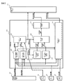
- the travel control device 201 in FIG. 1 includes a host vehicle peripheral information management unit 202 that manages external world information around the host vehicle, and a vehicle control unit 203 that controls the host vehicle based on the external world information.
- the rear radar 101, the front camera 102, and the all-around camera 103 are used to acquire external information around the host vehicle.
- the map information 104 and the locator 105 are used for acquiring road information and the position of the host vehicle.
- the own vehicle surrounding information management unit 202 outputs surrounding solid object information and surrounding road information to the vehicle control unit 203 based on data input from the sensors 101 to 107 and the like.
- the steering angle sensor 106 is used to acquire the steering wheel angle.
- the vehicle speed sensor 107 is used to acquire the speed of the host vehicle.
- the driver input 108 is used to acquire information input by the driver.
- the exercise manager device 301 is based on manual operation when the travel mode output from the travel control device 201 is in the automatic driving cancel mode, and when it is not in the automatic driving cancel mode, the vertical acceleration instruction value and the lateral acceleration instruction Based on the values, the drive actuator 401, the brake actuator 402, and the steering actuator 403 are controlled.
- the vehicle control unit 203 moves to the preceding vehicle based on the surrounding solid object information and the surrounding road information input from the own vehicle surrounding information management unit 202 and the rudder angle information acquired by the rudder angle sensor 106.
- a preceding vehicle follow-up execution determination unit 204 that makes a follow-up determination of the vehicle
- a lane line follow-up execution determination unit 205 that makes a follow-up determination to the lane line
- a driving mode selection unit 206 that selects a driving mode based on driver input information acquired by the driver input 108, and a preceding vehicle tracking that calculates a traveling locus based on preceding vehicle information determined by the preceding vehicle tracking execution determination unit 204.
- a lane line following run that calculates a running locus based on the surrounding locus information input from the traveling locus calculation unit 207 and the vehicle surrounding information management unit 202 Based on the trajectory calculation unit 208 and the travel mode selected by the travel mode selection unit 206, the travel trajectory information calculated by the preceding vehicle following travel trajectory calculation unit 207 and the travel trajectory calculated by the lane marking following travel trajectory calculation unit 208
- a travel locus selection unit 209 that selects a travel locus from the information
- a lateral acceleration instruction calculation unit 210 that calculates a lateral acceleration instruction value based on the travel locus selected by the travel locus selection unit 209
- the vehicle surrounding information management Steering angle information acquired by the steering angle sensor 106, the surrounding solid information input from the unit 202, the driving mode selected by the driving mode selection unit 206, the preceding vehicle information determined by the preceding vehicle follow-up execution determining unit 204
- a longitudinal acceleration instruction calculation unit 211 that calculates a longitudinal acceleration instruction value based on the vehicle speed information acquired by the vehicle speed
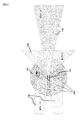
- FIG. 3 shows an example of the recognition range of the outside world in the present embodiment.
- the own vehicle F01 includes a rear radar F02, an all-around camera F03, a front camera F04, and a front radar F05, and has a detection system configuration capable of detecting information about the entire periphery of the own vehicle.
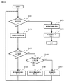
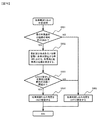
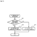
- FIG. 4 is a flowchart showing an embodiment of a travel mode selection processing procedure of the travel mode selection unit 206 when the present invention is applied to travel control.
- the travel mode is selected according to the object to be controlled. Specifically, the vehicle travels along a lane line following travel mode that travels along a lane line that divides the lane in which the host vehicle is traveling, It is determined which of the preceding vehicle following traveling mode for traveling following the preceding vehicle to be selected and the vehicle speed control mode such as CC with the own vehicle speed as the control target is selected.
- the lane line following traveling mode and the preceding vehicle following traveling mode are first modes in which the subject vehicle travels according to a control target set based on an object existing outside the subject vehicle. This is a second mode in which the host vehicle travels according to a control target set without depending on an object existing outside.
- the operation based on the flowchart is as follows.
- Step S101 If a vehicle control cancellation due to the driver's will or a vehicle control canceling factor due to fail-safe occurs, the process proceeds to step S201. Otherwise, the process proceeds to step S102.
- Vehicle control based on the driver's intention includes explicit automatic driving cancellation by a driver's switch operation and implicit automatic driving cancellation by a brake / handle operation.
- Step S102 A control target is selected, and the process proceeds to step S103.
- Step S103 If the control target is set to a lane marking, the process proceeds to step S105. If no, the process proceeds to step S104.
- Step S104 If the control target is set to the preceding vehicle, the process proceeds to step S106. If no, the process moves to step S107.
- Step S105 The traveling mode is set to the lane line following traveling mode, the instruction value by the lane line following control is calculated, and the process returns to step S101.
- Step S106 The traveling mode is set to the preceding vehicle following traveling mode, the instruction value by the preceding vehicle following control is calculated, and the process returns to step S101.
- Step S107 The travel mode is set to the vehicle speed control mode, an instruction value by vehicle speed control is calculated, and the process returns to step S101.
- Step S201 The driver is notified that vehicle control is to be released, and the process proceeds to step S202.
- Step S202 Transition to the automatic driving cancel mode, cancel the vehicle control, and end the process. Thereafter, the automatic driving cancellation mode is maintained until an automatic driving start instruction is given by the driver's intention.
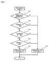
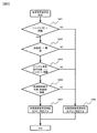
- FIG. 5 is a flowchart of step S102 (control target selection process). The operation based on the flowchart is as follows. Step S301: It is determined whether the lane marking can be controlled, and the process proceeds to Step S302. Step S302: The behavior stability of the preceding vehicle is determined, and the process proceeds to step S303. Step S303: The behavior stability of the host vehicle is determined, and the process proceeds to Step S304.
- Step S304 It is determined whether the traveling lane of the host vehicle can continue traveling, and the process proceeds to Step S305.
- Step S305 It is determined whether there is a possibility that another vehicle may interrupt the travel locus of the host vehicle, and the process proceeds to Step S306.
- Step S306 It is determined whether the traveling section is a section where the preceding vehicle can be followed, and the routine goes to Step S307.
- Step S307 If the follow-up control for the lane marking is possible, the process proceeds to step S308. If NO, the process moves to step S309.
- Step S309 If it is possible to control the preceding vehicle, the process proceeds to step S310. If NO, the process moves to step S311. Step S310: The control target is set to the preceding vehicle, and the process ends. Step S311: The control target is set to none, and the process ends.
- FIG. 6 is a flowchart of the step S301 (determination line tracking control enablement determination process). The operation based on the flowchart is as follows. Step S401: If the lane line information at the front gazing point can be acquired, the process proceeds to step S402. If no, the process moves to step S406. Step S402: When the traveling direction angle of the host vehicle with respect to the lane line (to the lane line yaw angle) is smaller than the threshold value, the process proceeds to step S403. If no, the process moves to step S406.
- Step S403 If the distance from the center of the vehicle to the left and right lane markings (horizontal position with respect to the lane marking) is larger than the threshold value, the process proceeds to step S404. If no, the process moves to step S406. Step S404: If the absolute value of the lateral acceleration of the host vehicle is smaller than the threshold value, the process proceeds to step S405. If no, the process moves to step S406. Step S405: The lane marking control permission determination is set to ON, and the process ends. Step S406: The lane marking control permission determination is set to OFF, and the process ends.
- FIG. 7 is a flowchart of step S302 (preceding vehicle behavior stability determination process). The operation based on the flowchart is as follows.
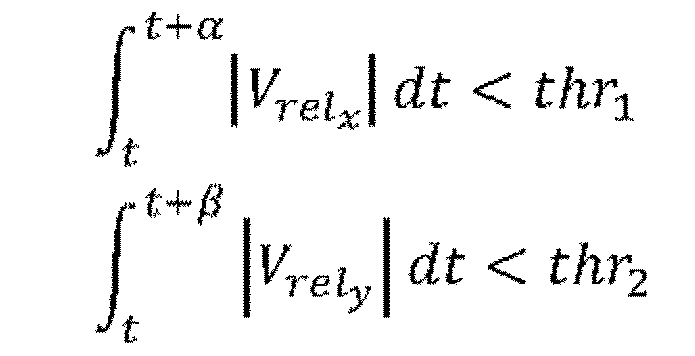
- Step S501 If the integrated values of the absolute values of the front-rear relative speed V relx and the lateral relative speed V rely of the preceding vehicle within a predetermined time are smaller than the threshold values thr 1 and thr 2 , the process proceeds to step S502. If NO, the process moves to step S505.
- Step S502 If the distance d from the estimated traveling path center of the vehicle threshold thr 3 smaller proceeds to step S503. If NO, the process moves to step S505.
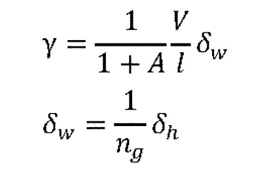
- the travel path of the host vehicle is estimated by the following formula. Here, the yaw rate ⁇ , the speed V of the host vehicle, the stability factor A, the wheel base 1, the front wheel turning angle ⁇ w , the steering wheel angle ⁇ h , and the steering gear ratio ng .
- Step S503 If the inter-vehicle distance d is larger than the threshold value thr 4 and smaller than the threshold value thr 5 , the process proceeds to step S504. If NO, the process moves to step S505.
- Step S504 The preceding vehicle behavior stability determination is set to ON, the current preceding vehicle information is stored, and the process ends.
- Step S505 The preceding vehicle behavior stability determination is set to OFF, the stored preceding vehicle information is deleted, and the process is terminated.
- FIG. 8 is a flowchart of step S303 (own vehicle behavior stability determination process). The operation based on the flowchart is as follows.
- Step S601 If the absolute value of the steering wheel angle [delta] h is the threshold value thr 6 smaller, the process proceeds to step S602. If NO, the process moves to step S606.
- Step S602 If the absolute value is the threshold value thr 7 and thr 8 smaller respectively the longitudinal acceleration a x and transverse acceleration a y, proceeds to step S603. If NO, the process moves to step S606.
- Step S605 The own vehicle behavior stability determination is set to ON, and the process ends.
- Step S606 The own vehicle behavior stability determination is set to OFF, and the process ends.
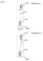
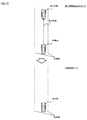
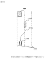
- FIG. 10, FIG. 11 and FIG. 12 show an example of a traveling scene in this embodiment.
- the lane marking control permission determination is ON in step S301, it is determined in step S307 that follow-up control for the lane line is possible, and the control target is set to the lane line in step S308, so that FIG.
- the lane marking follow-up control is performed as shown above.
- step S301 If no lane line information can be obtained, the lane line control permission determination is turned off in step S301, and it is determined in step S307 that tracking control for the lane line is impossible.
- step S307 At this time, if the preceding vehicle behavior stability determination is ON in step S302 and the own vehicle behavior stability determination is ON in step S303, it is determined in step S309 that the preceding vehicle can be controlled, and in step S310.
- the preceding vehicle following control is performed as shown in the lower diagram of FIG.
- step S301 If the lane marking control permission determination is OFF in step S301, and if the preceding vehicle behavior stability determination is OFF in step S302 or if the own vehicle behavior stability determination is OFF in step S303, the control target is determined in step S311.
- vehicle speed control is performed as shown in the lower diagram of FIG.
- the lane marking control permission determination is turned off in step S301, the preceding vehicle behavior stability determination is turned off in step S302, or the host vehicle behavior stability determination is turned off in step S303, and the travel mode is the vehicle speed control mode.
- the lane marking control permission determination is turned on while the loop of the flowchart of FIG. 4 is repeated after that, the lane line tracking travel mode is changed to the lane line tracking mode as shown in the lower diagram of FIG. Perform line following control.
- a process of returning to the lane line following traveling mode or the preceding vehicle following traveling mode is performed.
- the present embodiment is an example in the case where it is determined that the travel cannot be continued in Step S304 (the travel lane travel continuance determination process) in the first embodiment.
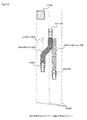
- FIG. 13 shows an example of a travel scene in the present embodiment.
- the host vehicle transitions from the lane line following control traveling mode to the preceding vehicle following traveling mode and is adjacent along the traveling locus of the preceding vehicle. Move to the lane.
- FIG. 5 and FIG. 9 only the steps changed from the first embodiment are shown below.
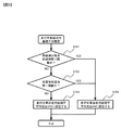
- FIG. 9 is a flowchart of step S304 of FIG.
- the operation based on the flowchart is as follows.
- Step S701 Based on road information in front of the host vehicle, a lane merge point, a lane decrease point of the traveling lane due to road construction / accident vehicle, etc. are acquired, and the arrival time of the host vehicle at the lane decrease point is smaller than a threshold value If so, the process moves to step S704. If NO, the process moves to step S702.
- Step S702 Based on the three-dimensional object information in front of the host vehicle, a point where the vehicle cannot travel due to the obstacle is acquired. If NO, the process moves to step S703.
- Step S703 The in-run lane travel continuation determination is set to OFF, and the process ends.
- Step S704 The in-run lane continuation inability determination is set to ON, and the process ends.
- Step S307 If the lane marking control permission determination is ON and the lane travel continuation prohibition determination is OFF, the process proceeds to step S308. In cases other than that described here, process flow proceeds to Step S309.
- step S704 when the continuation prohibition determination while driving in step S704 is set to ON, the process proceeds to step S309 based on the determination in step S307, and the preceding vehicle following traveling mode is entered when the preceding vehicle can be followed.
- the transition makes it possible to travel as shown in FIG.
- Example 3 The present embodiment is an example when it is determined that there is an interrupt possibility in step S305 (other vehicle interrupt determination processing) in the second embodiment.
- FIG. 14 shows an example of a traveling scene in the present embodiment. Even when trying to avoid obstacles by following the preceding vehicle, if it is determined that there is a high possibility that the following vehicle will be interrupted on the own vehicle traveling locus, the transition to the preceding vehicle following traveling mode is suppressed. To do.
- FIG. 16 is a flowchart of step S305 (other vehicle interruption determination process) in FIG.
- the operation based on the flowchart is as follows.
- Step S801 If the in-travel lane travel impossibility determination is set to ON in Step S304 of FIG. 5, the process proceeds to Step S802. If it is set to OFF, the process proceeds to step S805.
- Step S802 The position of the host vehicle at the time of arrival of the host vehicle at the lane decrease point calculated at step S701 of FIG. 9 or the time of arrival of the host vehicle at the point where the obstacle cannot travel calculated at step S702 of FIG. Estimate the position of another vehicle.
- Step S803 If there is at least one other vehicle in which the distance between the position of the host vehicle estimated in step S802 and the position of the other vehicle is smaller than the threshold, the process proceeds to step S804. If there is no such other vehicle, the process proceeds to step S805.
- Step S804 The other vehicle interruption determination is set to ON, and the process is terminated.
- Step S805 The other vehicle interruption determination is set to OFF, and the process is terminated.
- Step S309 If the preceding vehicle behavior stability determination is ON, the own vehicle behavior stability determination is ON, and the other vehicle interrupt determination is OFF, the process proceeds to Step S310. In cases other than that described here, process flow proceeds to Step S311.
- step S804 When the other vehicle interrupt determination is set to ON in step S804 by the above operation, the process proceeds to step S311 based on the determination in step S309, and transitions to the vehicle speed control mode. As shown in FIG. 14, when it is determined that there is a high possibility that the following vehicle will fall on the own vehicle traveling locus, the transition to the preceding vehicle following traveling mode is suppressed and the transition to the vehicle speed control mode is performed. It becomes possible.
- Example 4 The present embodiment is an example in the case where it is determined in step S306 (preceding vehicle followable section determination process) in the first embodiment that the preceding vehicle followable section is not possible.
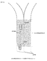
- FIG. 15 shows an example of a traveling scene in the present embodiment.
- the preceding vehicle follow-up suppression section is set from x 1 [m] before the road branch to x 2 [m] after the branch and the host vehicle enters the preceding vehicle follow-up suppression section, the preceding vehicle behavior stability determination is ON and Even if the own vehicle behavior stability determination is ON, the transition to the preceding vehicle following traveling mode is not performed.
- FIG. 17 is a flowchart of step S306 (preceding vehicle followable section determination process) in FIG.
- the operation based on the flowchart is as follows.
- Step S901 Based on the information on the preceding vehicle follow-up suppression section included in the surrounding road information output from the own vehicle surrounding information management unit 202, it is determined whether or not the own vehicle is traveling in the preceding vehicle follow-up suppression section. If it is within the preceding vehicle follow-up suppression section, the process proceeds to step S902. If it is outside the preceding vehicle follow-up suppression section, the process proceeds to step S903.
- Step S902 The preceding vehicle followable section determination is set to OFF, and the process ends.
- Step S903 The preceding vehicle followable section determination is set to ON, and the process ends.
- Step S309 If the preceding vehicle behavior stability determination is ON, the own vehicle behavior stability determination is ON, and the preceding vehicle followable section determination is ON, the process proceeds to Step S310. In cases other than that described here, process flow proceeds to Step S311.
- step S902 If the preceding vehicle followable section determination is set to OFF in step S902 by the above operation, the process proceeds to step S311 based on the determination in step S309, and transitions to the vehicle speed control mode. As shown in FIG. 15, when the host vehicle enters the preceding vehicle follow-up suppression section, it is possible to suppress the transition to the preceding vehicle follow-up travel mode and make a transition to the vehicle speed control mode.
- Step S309 If the preceding vehicle behavior stability determination is ON, the own vehicle behavior stability determination is ON, the other vehicle interrupt determination is OFF, and the preceding vehicle followable section determination is ON, the process proceeds to Step S310. In cases other than that described here, process flow proceeds to Step S311.
Landscapes
- Engineering & Computer Science (AREA)
- Transportation (AREA)
- Mechanical Engineering (AREA)
- Automation & Control Theory (AREA)
- Chemical & Material Sciences (AREA)
- Combustion & Propulsion (AREA)
- Physics & Mathematics (AREA)
- Radar, Positioning & Navigation (AREA)
- Remote Sensing (AREA)
- Computer Vision & Pattern Recognition (AREA)
- Aviation & Aerospace Engineering (AREA)
- General Physics & Mathematics (AREA)
- Multimedia (AREA)
- Electromagnetism (AREA)
- Mathematical Physics (AREA)
- Control Of Driving Devices And Active Controlling Of Vehicle (AREA)
- Traffic Control Systems (AREA)
Abstract
Description
本実施形態の走行制御装置は、自車両の外部に存在する物体に基づいて設定される制御目標に従って自車両を走行させる第1のモードと、自車両の外部に存在する物体に依らずに設定される制御目標に従って自車両を走行させる第2のモードとを有する。そして、第1のモードで走行中に自車両の外部に存在する物体に基づいて制御目標を設定することが不可能となった場合には第2のモードに移行する。また、第2のモードで走行中に自車両の外部に存在する物体に基づいて制御目標を設定することが可能となった場合には第1のモードに移行する。
[実施例1]
図1の走行制御装置201は、自車両の周囲の外界情報を管理する自車両周辺情報管理部202と、前記外界情報に基づいて自車両を制御する車両制御部203を有する。
ここでは、制御対象に応じて走行モードが選択され、具体的には、自車両の走行中の車線を区画する区画線に沿った走行を行う区画線追従走行モードと、自車両の前方を走行する先行車両に追従して走行する先行車両追従走行モードと、自車速を制御目標としたCCなどの車速制御モードのいずれを選択するかが判断される。区画線追従走行モードと先行車両追従走行モードは、自車両の外部に存在する物体に基づいて設定される制御目標に従って自車両を走行させる第1のモードであり、車速制御モードは、自車両の外部に存在する物体に依らずに設定される制御目標に従って自車両を走行させる第2のモードである。フローチャートに基づく動作は以下の通りである。
ステップS101:ドライバの意志による車両制御の解除、またはフェールセーフによる車両制御キャンセル要因が発生した場合には、ステップS201に移る。そうでない場合は、ステップS102に移る。ドライバの意思による車両制御には、ドライバのスイッチ操作による明示的な自動運転解除や、ブレーキ・ハンドル等の操作による暗黙的な自動運転解除を含む。
ステップS103:制御対象が区画線に設定されている場合は、ステップS105に移る。NOの場合は、ステップS104へ移る。
ステップS104:制御対象が先行車両に設定されている場合は、ステップS106に移る。NOの場合は、ステップS107に移る。
ステップS106:走行モードを先行車両追従走行モードに設定し、先行車両追従制御による指示値を算出し、ステップS101に戻る。
ステップS107:走行モードを車速制御モードに設定し、車速制御による指示値を算出し、ステップS101に戻る。
ステップS202:自動運転解除モードに移行し、車両制御を解除して処理を終了する。以後、ドライバの意思による自動運転の開始指示があるまで自動運転解除モードを維持する。
ステップS301:区画線に対する制御が可能か判定し、ステップS302に移る。
ステップS302:先行車両の挙動安定性を判定し、ステップS303に移る。
ステップS303:自車両の挙動安定性を判定し、ステップS304に移る。
ステップS305:自車両の走行軌跡上に他車両が割り込む可能性があるかを判定し、ステップS306に移る。
ステップS307:区画線に対する追従制御が可能である場合、ステップS308に移る。NOの場合は、ステップS309に移る。
ステップS308:制御対象を区画線に設定し、処理を終了する。
NOの場合は、ステップS311に移る。
ステップS310:制御対象を先行車両に設定し、処理を終了する。
ステップS311:制御対象を無しに設定し、処理を終了する。
ステップS401:前方注視点における区画線情報が取得可能な場合は、ステップS402に移る。NOの場合は、ステップS406に移る。
ステップS402:区画線に対する自車両の進行方向角度(対区画線ヨー角)が閾値よりも小さい場合は、ステップS403に移る。NOの場合は、ステップS406に移る。
ステップS404:自車両の横方向加速度の絶対値が閾値より小さい場合は、ステップS405に移る。NOの場合は、ステップS406に移る。
ステップS405:区画線制御許可判定をONに設定し、処理を終了する。
ステップS406:区画線制御許可判定をOFFに設定し、処理を終了する。

ステップS602:前後方向加速度axおよび横方向加速度ayの絶対値がそれぞれ閾値thr7およびthr8より小さい場合は、ステップS603に移る。NOの場合は、ステップS606に移る。
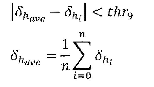
ステップS603:ハンドル角度の移動平均値δhaveと各処理周期におけるハンドル角度δhi(i=0,1,2,…,n)との差分が閾値thr9より小さい場合は、ステップS604に移る。NOの場合は、ステップS606に移る。
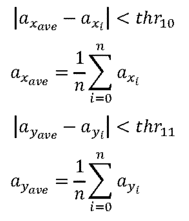
ステップS606:自車両挙動安定判定をOFFに設定し、処理を終了する。
このように走行制御を解除することなく車両制御を継続することが可能である。
本実施例は、実施例1におけるステップS304(走行中車線走行継続不可判定処理)において、走行継続不可と判断された場合の例である。
図13は、本実施例における走行シーンの一例を示している。先行車両が走行中の車線上の障害物を避けるために隣接車線に移動した際、自車両は区画線追従制御走行モードから先行車両追従走行モードに遷移し、先行車両の走行軌跡に沿って隣接車線に移動する。
図5、図9を参照し、実施例1から変更があるステップのみ、以下に示す。
ステップS701:自車両前方の道路情報に基づき、車線合流地点、道路工事・事故車両等による自車両走行中車線の車線減少地点を取得し、車線減少地点への自車両の到達時間が閾値より小さい場合は、ステップS704に移る。NOの場合は、ステップS702に移る。
ステップS703:走行中車線走行継続不可判定をOFFに設定し、処理を終了する。
ステップS307:区画線制御許可判定がON、かつ走行中車線走行継続不可判定がOFFである場合は、ステップS308に移る。それ以外の場合はステップS309に移る。
本実施例は、実施例2におけるステップS305(他車両割り込み判定処理)において、割込み可能性有りと判断された場合の例である。
図16は、図5のステップS305(他車両割り込み判定処理)のフローチャートである。フローチャートに基づく動作は以下の通りである。
ステップS802:図9のステップS701で算出した車線減少地点への自車両の到達時間、あるいは図9のステップS702で算出した障害物による走行不可地点への自車両の到達時間における自車両の位置と他車両の位置を推定する。
ステップS804:他車両割り込み判定をONに設定し、処理を終了する。
ステップS805:他車両割り込み判定をOFFに設定し、処理を終了する。
本実施例は、実施例1におけるステップS306(先行車両追従可能区間判定処理)において、先行車両追従不可区間と判断された場合の例である。
図17は、図5のステップS306(先行車両追従可能区間判定処理)のフローチャートである。フローチャートに基づく動作は以下の通りである。
ステップS902:先行車両追従可能区間判定をOFFに設定し、処理を終了する。
ステップS903:先行車両追従可能区間判定をONに設定し、処理を終了する。
ステップS309:先行車両挙動安定判定がONかつ、自車両挙動安定判定がON、かつ他車両割り込み判定がOFF、かつ先行車両追従可能区間判定がONである場合はステップS310に移る。それ以外の場合はステップS311に移る。
Claims (11)
- 自車両の外部に存在する物体に基づいて設定される制御目標に従って自車両を走行させる第1のモードと、
自車両の外部に存在する物体に依らずに設定される制御目標に従って自車両を走行させる第2のモードと、を有し、
前記第2のモードで走行中に自車両の外部に存在する物体に基づいて制御目標を設定することが可能となった場合、第1のモードに移行する、走行制御装置。 - 前記第1のモードで走行中に自車両の外部に存在する物体に基づいて制御目標を設定することが困難な状況となった場合、前記第2のモードに移行する、請求項1に記載の走行制御装置。
- 前記第1のモードの制御目標は、自車両の走行中の車線を区画する区画線、又は、自車両の前方を走行する先行車に基づいて設定される、請求項1に記載の走行制御装置。
- 前記第1のモードとして、自車両の走行中の車線を区画する区画線に沿った走行を行う区画線追従走行モードと、
自車両の前方を走行する先行車に追従して走行する先行車両追従走行モードと、を有する、請求項1に記載の走行制御装置。 - 前記第2のモードとして、自車両の車速を制御目標とする車速制御モードを有する、請求項1に記載の走行制御装置。
- 前記区画線追従走行モードで前記走行中の車線を走行している状態から前記区画線に沿った走行が困難な状態となった際、追従走行可能条件を満たす車両が自車両前方に存在する場合には、前記先行車両追従走行モードに切り替える、請求項4に記載の走行制御装置。
- 前記区画線追従走行モードで前記走行中の車線を走行している状態から前記区画線に沿った走行が困難な状態となった際、前記追従走行可能条件を満たす車両が自車両前方に存在しない場合には、少なくとも自車両の車速制御を継続する、請求項4に記載の走行制御装置。
- 前記区画線追従走行モード及び先行車両追従走行モードでは、操舵制御及び車速制御を行い、
前記追従走行可能条件を満たす車両が自車両前方に存在しない場合には、舵角制御を行わずに車速制御を行うことを特徴とする、請求項6に記載の走行制御装置。 - 前記車速制御を継続している状態で前記区画線又は前記先行車両が検出された場合には、前記区画線追従走行モード、又は前記先行車両追従走行モードに復帰することを特徴とする、請求項4に記載の走行制御装置。
- 後続車両が自車走行軌跡上に割り込んでくる可能性が高いと判断された場合には、前記先行車両追従走行モードへの切り替えを抑制することを特徴とする、請求項6に記載の走行制御装置。
- 前記自車両が予め設定された先行車両追従抑制区間を走行していると判断された場合には、前記先行車両追従走行モードへの切り替えを抑制することを特徴とする、請求項6に記載の走行制御装置。
Priority Applications (2)
| Application Number | Priority Date | Filing Date | Title |
|---|---|---|---|
| US15/761,193 US10654477B2 (en) | 2015-10-15 | 2016-09-20 | Vehicle control device |
| JP2017545129A JPWO2017064981A1 (ja) | 2015-10-15 | 2016-09-20 | 車両制御装置 |
Applications Claiming Priority (2)
| Application Number | Priority Date | Filing Date | Title |
|---|---|---|---|
| JP2015203341 | 2015-10-15 | ||
| JP2015-203341 | 2015-10-15 |
Publications (1)
| Publication Number | Publication Date |
|---|---|
| WO2017064981A1 true WO2017064981A1 (ja) | 2017-04-20 |
Family
ID=58517584
Family Applications (1)
| Application Number | Title | Priority Date | Filing Date |
|---|---|---|---|
| PCT/JP2016/077618 Ceased WO2017064981A1 (ja) | 2015-10-15 | 2016-09-20 | 車両制御装置 |
Country Status (3)
| Country | Link |
|---|---|
| US (1) | US10654477B2 (ja) |
| JP (3) | JPWO2017064981A1 (ja) |
| WO (1) | WO2017064981A1 (ja) |
Cited By (4)
| Publication number | Priority date | Publication date | Assignee | Title |
|---|---|---|---|---|
| JP2018020628A (ja) * | 2016-08-02 | 2018-02-08 | いすゞ自動車株式会社 | 操舵補助装置及び操舵補助方法 |
| CN109572670A (zh) * | 2017-09-28 | 2019-04-05 | 丰田自动车株式会社 | 驾驶辅助装置 |
| CN109591797A (zh) * | 2017-09-28 | 2019-04-09 | 丰田自动车株式会社 | 驾驶辅助装置 |
| CN110406533A (zh) * | 2018-04-27 | 2019-11-05 | 株式会社万都 | 提高前方车辆跟随器纵向控制的安全性的车道保持辅助系统和方法 |
Families Citing this family (9)
| Publication number | Priority date | Publication date | Assignee | Title |
|---|---|---|---|---|
| JP6321532B2 (ja) * | 2014-11-28 | 2018-05-09 | 株式会社デンソー | 車両の走行制御装置 |
| JP6485792B2 (ja) * | 2017-03-17 | 2019-03-20 | マツダ株式会社 | 運転支援制御装置 |
| JP6725568B2 (ja) * | 2018-03-13 | 2020-07-22 | 本田技研工業株式会社 | 車両制御装置、車両、車両制御方法およびプログラム |
| JP7303667B2 (ja) * | 2019-05-31 | 2023-07-05 | 株式会社Subaru | 自動運転支援装置 |
| DE102019217922B4 (de) * | 2019-11-20 | 2023-08-03 | Robert Bosch Gmbh | Verfahren zum Betrieb eines Fahrzeugs |
| JP7215596B2 (ja) * | 2019-11-28 | 2023-01-31 | 日産自動車株式会社 | 運転制御方法及び運転制御装置 |
| WO2021168452A2 (en) * | 2020-02-21 | 2021-08-26 | Bluespace Al, Inc. | Method for object avoidance during autonomous navigation |
| CN117922455A (zh) * | 2023-03-20 | 2024-04-26 | 小米汽车科技有限公司 | 联动系统、方法、车辆、存储介质与芯片 |
| WO2026013768A1 (ja) * | 2024-07-09 | 2026-01-15 | Ntt株式会社 | 仮想現実体験制御装置、方法およびプログラム |
Citations (4)
| Publication number | Priority date | Publication date | Assignee | Title |
|---|---|---|---|---|
| JP2001022444A (ja) * | 1999-07-05 | 2001-01-26 | Honda Motor Co Ltd | 車両用操舵制御装置 |
| JP2004206275A (ja) * | 2002-12-24 | 2004-07-22 | Denso Corp | 自動運転制御システム |
| JP2009003795A (ja) * | 2007-06-22 | 2009-01-08 | Fuji Heavy Ind Ltd | 分岐路進入判定装置 |
| JP2014058229A (ja) * | 2012-09-18 | 2014-04-03 | Daimler Ag | 運転支援装置 |
Family Cites Families (8)
| Publication number | Priority date | Publication date | Assignee | Title |
|---|---|---|---|---|
| JP2001023094A (ja) * | 1999-07-12 | 2001-01-26 | Nissan Motor Co Ltd | 半自動運転システム |
| JP3964287B2 (ja) * | 2002-09-04 | 2007-08-22 | 富士重工業株式会社 | 車外監視装置、及び、この車外監視装置を備えた走行制御装置 |
| JP4379199B2 (ja) * | 2004-05-17 | 2009-12-09 | 日産自動車株式会社 | 車線変更支援装置および方法 |
| JP4735310B2 (ja) * | 2005-04-15 | 2011-07-27 | 株式会社デンソー | 走行支援装置 |
| JP4781707B2 (ja) * | 2005-04-15 | 2011-09-28 | 富士重工業株式会社 | 車両の運転支援装置 |
| US8948954B1 (en) * | 2012-03-15 | 2015-02-03 | Google Inc. | Modifying vehicle behavior based on confidence in lane estimation |
| US9180882B1 (en) * | 2012-06-20 | 2015-11-10 | Google Inc. | Avoiding blind spots of other vehicles |
| CN104870293A (zh) * | 2012-12-11 | 2015-08-26 | 丰田自动车株式会社 | 驾驶辅助装置以及驾驶辅助方法 |
-
2016
- 2016-09-20 US US15/761,193 patent/US10654477B2/en active Active
- 2016-09-20 JP JP2017545129A patent/JPWO2017064981A1/ja active Pending
- 2016-09-20 WO PCT/JP2016/077618 patent/WO2017064981A1/ja not_active Ceased
-
2020
- 2020-01-09 JP JP2020001786A patent/JP6871437B2/ja active Active
-
2021
- 2021-04-15 JP JP2021068777A patent/JP7213909B2/ja active Active
Patent Citations (4)
| Publication number | Priority date | Publication date | Assignee | Title |
|---|---|---|---|---|
| JP2001022444A (ja) * | 1999-07-05 | 2001-01-26 | Honda Motor Co Ltd | 車両用操舵制御装置 |
| JP2004206275A (ja) * | 2002-12-24 | 2004-07-22 | Denso Corp | 自動運転制御システム |
| JP2009003795A (ja) * | 2007-06-22 | 2009-01-08 | Fuji Heavy Ind Ltd | 分岐路進入判定装置 |
| JP2014058229A (ja) * | 2012-09-18 | 2014-04-03 | Daimler Ag | 運転支援装置 |
Cited By (15)
| Publication number | Priority date | Publication date | Assignee | Title |
|---|---|---|---|---|
| US11148716B2 (en) | 2016-08-02 | 2021-10-19 | Isuzu Motors Limited | Steering assistance device and steering assistance method |
| WO2018025750A1 (ja) * | 2016-08-02 | 2018-02-08 | いすゞ自動車株式会社 | 操舵補助装置及び操舵補助方法 |
| JP2018020628A (ja) * | 2016-08-02 | 2018-02-08 | いすゞ自動車株式会社 | 操舵補助装置及び操舵補助方法 |
| CN109572670A (zh) * | 2017-09-28 | 2019-04-05 | 丰田自动车株式会社 | 驾驶辅助装置 |
| CN109591797A (zh) * | 2017-09-28 | 2019-04-09 | 丰田自动车株式会社 | 驾驶辅助装置 |
| US11535295B2 (en) | 2017-09-28 | 2022-12-27 | Toyota Jidosha Kabushiki Kaisha | Driving support apparatus |
| CN109591797B (zh) * | 2017-09-28 | 2022-03-04 | 丰田自动车株式会社 | 驾驶辅助装置 |
| US10759477B2 (en) | 2017-09-28 | 2020-09-01 | Toyota Jidosha Kabushiki Kaisha | Driving support apparatus |
| CN109572670B (zh) * | 2017-09-28 | 2022-01-18 | 丰田自动车株式会社 | 驾驶辅助装置 |
| EP3581451A1 (en) * | 2018-04-27 | 2019-12-18 | Mando Corporation | Lane keeping assist system and method for improving safety in preceding vehicle follower longitudinal control |
| US11097726B2 (en) | 2018-04-27 | 2021-08-24 | Mando Corporation | Lane keeping assist system and method for improving safety in preceding vehicle follower longitudinal control |
| US11001258B2 (en) | 2018-04-27 | 2021-05-11 | Mando Corporation | Lane keeping assist system and method for improving safety in preceding vehicle follower longitudinal control |
| KR20190125013A (ko) * | 2018-04-27 | 2019-11-06 | 주식회사 만도 | 전방 차량 추종 제어 시 안전성을 향상할 수 있는 차선 유지 보조 시스템 및 방법 |
| CN110406533A (zh) * | 2018-04-27 | 2019-11-05 | 株式会社万都 | 提高前方车辆跟随器纵向控制的安全性的车道保持辅助系统和方法 |
| KR102553247B1 (ko) * | 2018-04-27 | 2023-07-07 | 주식회사 에이치엘클레무브 | 전방 차량 추종 제어 시 안전성을 향상할 수 있는 차선 유지 보조 시스템 및 방법 |
Also Published As
| Publication number | Publication date |
|---|---|
| JP7213909B2 (ja) | 2023-01-27 |
| JP6871437B2 (ja) | 2021-05-12 |
| JPWO2017064981A1 (ja) | 2018-06-21 |
| US20180257648A1 (en) | 2018-09-13 |
| JP2020073376A (ja) | 2020-05-14 |
| US10654477B2 (en) | 2020-05-19 |
| JP2021119076A (ja) | 2021-08-12 |
Similar Documents
| Publication | Publication Date | Title |
|---|---|---|
| JP6871437B2 (ja) | 車両制御装置 | |
| CN107735309B (zh) | 车道脱离抑制装置 | |
| CN109484400B (zh) | 车辆的行驶控制装置 | |
| EP1840000B1 (en) | Lane keeping assistance equipment for automotive vehicles | |
| US10755573B2 (en) | Collision avoidance device | |
| JP6323572B2 (ja) | 目標車速生成装置および走行制御装置 | |
| CN109963760B (zh) | 车辆控制装置 | |
| CN110446641B (zh) | 车辆控制装置和车辆控制方法 | |
| US11939015B2 (en) | Vehicle control device and vehicle control method | |
| JP5853552B2 (ja) | 車両用走行制御装置 | |
| CN109641590B (zh) | 车辆控制装置 | |
| CN111619573A (zh) | 车辆控制装置 | |
| CN114179904B (zh) | 车辆控制方法及车辆控制装置 | |
| CN112714730B (zh) | 用于运行至少部分自动化运行的第一车辆的方法和设备 | |
| JP6419671B2 (ja) | 車両用操舵装置および車両用操舵方法 | |
| JP2015209129A (ja) | 車両の操舵制御装置 | |
| JP2024060021A (ja) | 車両制御システム及び方法 | |
| US20220165071A1 (en) | Method for controlling the positioning of a motor vehicle on a traffic lane | |
| US11507085B2 (en) | Vehicle control apparatus | |
| WO2016194722A1 (ja) | 運転支援装置 | |
| JP2016045636A (ja) | 移動物体進路予測装置 | |
| JP2008059366A (ja) | 操舵角決定装置、自動車及び操舵角決定方法 | |
| CN113039109A (zh) | 用于在跟随行驶中对车辆进行横向引导的方法和控制单元 | |
| EP3354541A1 (en) | Driver assistance system for overcoming a bump | |
| JP2018203156A (ja) | 車両用操舵装置および車両操舵制御方法 |
Legal Events
| Date | Code | Title | Description |
|---|---|---|---|
| 121 | Ep: the epo has been informed by wipo that ep was designated in this application |
Ref document number: 16855235 Country of ref document: EP Kind code of ref document: A1 |
|
| ENP | Entry into the national phase |
Ref document number: 2017545129 Country of ref document: JP Kind code of ref document: A |
|
| WWE | Wipo information: entry into national phase |
Ref document number: 15761193 Country of ref document: US |
|
| NENP | Non-entry into the national phase |
Ref country code: DE |
|
| 122 | Ep: pct application non-entry in european phase |
Ref document number: 16855235 Country of ref document: EP Kind code of ref document: A1 |