WO2017057214A1 - シリンダ装置 - Google Patents
シリンダ装置 Download PDFInfo
- Publication number
- WO2017057214A1 WO2017057214A1 PCT/JP2016/078156 JP2016078156W WO2017057214A1 WO 2017057214 A1 WO2017057214 A1 WO 2017057214A1 JP 2016078156 W JP2016078156 W JP 2016078156W WO 2017057214 A1 WO2017057214 A1 WO 2017057214A1
- Authority
- WO
- WIPO (PCT)
- Prior art keywords
- flow path
- cylinder
- inner cylinder
- notch
- clockwise
- Prior art date
- Legal status (The legal status is an assumption and is not a legal conclusion. Google has not performed a legal analysis and makes no representation as to the accuracy of the status listed.)
- Ceased
Links
Images



Classifications
-
- F—MECHANICAL ENGINEERING; LIGHTING; HEATING; WEAPONS; BLASTING
- F16—ENGINEERING ELEMENTS AND UNITS; GENERAL MEASURES FOR PRODUCING AND MAINTAINING EFFECTIVE FUNCTIONING OF MACHINES OR INSTALLATIONS; THERMAL INSULATION IN GENERAL
- F16F—SPRINGS; SHOCK-ABSORBERS; MEANS FOR DAMPING VIBRATION
- F16F9/00—Springs, vibration-dampers, shock-absorbers, or similarly-constructed movement-dampers using a fluid or the equivalent as damping medium
- F16F9/32—Details
- F16F9/53—Means for adjusting damping characteristics by varying fluid viscosity, e.g. electromagnetically
-
- F—MECHANICAL ENGINEERING; LIGHTING; HEATING; WEAPONS; BLASTING
- F16—ENGINEERING ELEMENTS AND UNITS; GENERAL MEASURES FOR PRODUCING AND MAINTAINING EFFECTIVE FUNCTIONING OF MACHINES OR INSTALLATIONS; THERMAL INSULATION IN GENERAL
- F16F—SPRINGS; SHOCK-ABSORBERS; MEANS FOR DAMPING VIBRATION
- F16F9/00—Springs, vibration-dampers, shock-absorbers, or similarly-constructed movement-dampers using a fluid or the equivalent as damping medium
- F16F9/32—Details
- F16F9/3207—Constructional features
- F16F9/3235—Constructional features of cylinders
-
- F—MECHANICAL ENGINEERING; LIGHTING; HEATING; WEAPONS; BLASTING
- F16—ENGINEERING ELEMENTS AND UNITS; GENERAL MEASURES FOR PRODUCING AND MAINTAINING EFFECTIVE FUNCTIONING OF MACHINES OR INSTALLATIONS; THERMAL INSULATION IN GENERAL
- F16F—SPRINGS; SHOCK-ABSORBERS; MEANS FOR DAMPING VIBRATION
- F16F9/00—Springs, vibration-dampers, shock-absorbers, or similarly-constructed movement-dampers using a fluid or the equivalent as damping medium
- F16F9/32—Details
- F16F9/34—Special valve constructions; Shape or construction of throttling passages
- F16F9/346—Throttling passages in the form of slots arranged in cylinder walls
-
- F—MECHANICAL ENGINEERING; LIGHTING; HEATING; WEAPONS; BLASTING
- F16—ENGINEERING ELEMENTS AND UNITS; GENERAL MEASURES FOR PRODUCING AND MAINTAINING EFFECTIVE FUNCTIONING OF MACHINES OR INSTALLATIONS; THERMAL INSULATION IN GENERAL
- F16F—SPRINGS; SHOCK-ABSORBERS; MEANS FOR DAMPING VIBRATION
- F16F2224/00—Materials; Material properties
- F16F2224/04—Fluids
- F16F2224/043—Fluids electrorheological
-
- F—MECHANICAL ENGINEERING; LIGHTING; HEATING; WEAPONS; BLASTING
- F16—ENGINEERING ELEMENTS AND UNITS; GENERAL MEASURES FOR PRODUCING AND MAINTAINING EFFECTIVE FUNCTIONING OF MACHINES OR INSTALLATIONS; THERMAL INSULATION IN GENERAL
- F16F—SPRINGS; SHOCK-ABSORBERS; MEANS FOR DAMPING VIBRATION
- F16F2224/00—Materials; Material properties
- F16F2224/04—Fluids
- F16F2224/045—Fluids magnetorheological
-
- F—MECHANICAL ENGINEERING; LIGHTING; HEATING; WEAPONS; BLASTING
- F16—ENGINEERING ELEMENTS AND UNITS; GENERAL MEASURES FOR PRODUCING AND MAINTAINING EFFECTIVE FUNCTIONING OF MACHINES OR INSTALLATIONS; THERMAL INSULATION IN GENERAL
- F16F—SPRINGS; SHOCK-ABSORBERS; MEANS FOR DAMPING VIBRATION
- F16F2230/00—Purpose; Design features
- F16F2230/02—Surface features, e.g. notches or protuberances
-
- F—MECHANICAL ENGINEERING; LIGHTING; HEATING; WEAPONS; BLASTING
- F16—ENGINEERING ELEMENTS AND UNITS; GENERAL MEASURES FOR PRODUCING AND MAINTAINING EFFECTIVE FUNCTIONING OF MACHINES OR INSTALLATIONS; THERMAL INSULATION IN GENERAL
- F16F—SPRINGS; SHOCK-ABSORBERS; MEANS FOR DAMPING VIBRATION
- F16F2230/00—Purpose; Design features
- F16F2230/18—Control arrangements
-
- F—MECHANICAL ENGINEERING; LIGHTING; HEATING; WEAPONS; BLASTING
- F16—ENGINEERING ELEMENTS AND UNITS; GENERAL MEASURES FOR PRODUCING AND MAINTAINING EFFECTIVE FUNCTIONING OF MACHINES OR INSTALLATIONS; THERMAL INSULATION IN GENERAL
- F16F—SPRINGS; SHOCK-ABSORBERS; MEANS FOR DAMPING VIBRATION
- F16F2230/00—Purpose; Design features
- F16F2230/36—Holes, slots or the like
Definitions
- the present invention relates to a cylinder device suitably used for buffering vibrations of vehicles such as automobiles and railway vehicles.
- Patent Document 1 discloses a configuration in which a spiral member is provided between an inner cylinder and an outer cylinder in a damper (buffer) using an electrorheological fluid, and a flow path is provided between the spiral members. ing.
- the cylinder device it is necessary for the cylinder device to have different damping force characteristics according to the type, size, model, specification, etc. of the vehicle to be mounted.
- An object of the present invention is to provide a cylinder device that can easily change and distinguish (discriminate) the damping force characteristics.
- a cylinder device includes an inner cylinder into which a functional fluid whose fluid properties are changed by an electric field or a magnetic field is sealed, and a rod inserted therein, an outer cylinder, and an electrode or A cylindrical member that functions as a magnetic pole, and a flow path forming member that is provided between the inner cylinder and the cylindrical member, and the functional fluid is caused to move forward and backward by the rod, at one end side in the axial direction of the cylinder device
- a flow path forming member that forms one or a plurality of flow paths that flow toward the other end side, the flow path is a spiral or meandering flow path having a portion extending in the circumferential direction,
- the flow path forming member is formed with a notch that allows the adjacent portions in the axial direction of the flow path to communicate with each other.
- the cylinder device of one embodiment of the present invention it is possible to easily change and distinguish (discriminate) the damping force characteristics.
- the longitudinal cross-sectional view which shows the shock absorber as a cylinder apparatus by 1st Embodiment.
- the perspective view which shows the ring-shaped member in FIG.
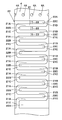
- the expanded view which expand
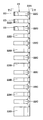
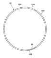
- the side view of a ring-shaped member The top view of a ring-shaped member.
- a shock absorber 1 as a cylinder device includes a damping force adjustment type hydraulic shock absorber (semi-conductor) that uses a functional fluid (that is, an electrorheological fluid) as a working oil (a working fluid 20 described later) sealed inside. Active damper).
- the shock absorber 1 constitutes a suspension device for a vehicle together with a suspension spring (not shown) made of, for example, a coil spring.
- a suspension spring not shown
- one end side of the shock absorber 1 in the axial direction is referred to as an “upper end” side
- the other end side in the axial direction is referred to as a “lower end” side.
- the shock absorber 1 includes an outer cylinder 2, an inner cylinder 4, a piston 5, a piston rod 8, an electrode cylinder 17, a ring-shaped member 22, and the like.
- the outer cylinder 2 forms an outer shell of the shock absorber 1 and is formed as a cylindrical body.
- the outer cylinder 2 has a closed end whose lower end is closed by a bottom cap 3 using welding means or the like.
- the bottom cap 3 constitutes a base member together with a valve body 13 of the bottom valve 12 described later.
- the upper end side of the outer cylinder 2 serves as an opening end, and a caulking portion 2A is formed at the opening end side by bending inward in the radial direction.
- the caulking portion 2A holds the outer peripheral side of the annular plate 11A of the seal member 11 in a retaining state.
- the inner cylinder 4 is formed as a cylindrical cylinder extending in the axial direction and encloses a working fluid 20 (that is, a functional fluid) described later.
- the inner cylinder 4 is provided coaxially with the outer cylinder 2 in the outer cylinder 2, and a piston rod 8 described later is inserted into the inner cylinder 4.
- the lower end side of the inner cylinder 4 is fitted and attached to the valve body 13 of the bottom valve 12, and the upper end side is fitted and attached to the rod guide 9.
- the inner cylinder 4 is formed with a plurality of (for example, four) oil holes 4 ⁇ / b> A that are always in communication with a flow path 21 to be described later and spaced apart in the circumferential direction as radial lateral holes.
- the rod side oil chamber B in the inner cylinder 4 communicates with the flow path 21 through the oil hole 4A.
- the inner cylinder 4 constitutes a cylinder together with the outer cylinder 2, and a working fluid 20 is enclosed in the cylinder.
- an electrorheological fluid EMF: Electro Rheological Fluid
- the fluid that is filled (enclosed) in the cylinder that is, the working fluid 20 that serves as the working oil.
- the enclosed working fluid 20 is colorless and transparent.
- An electrorheological fluid is a type of functional fluid whose properties change with an electric field
- an electrorheological fluid is a fluid whose properties change with an electric field (voltage). That is, the flow resistance (damping force) of the electrorheological fluid changes according to the applied voltage.
- the electrorheological fluid is composed of, for example, a base oil (base oil) made of silicon oil or the like, and particles (fine particles) mixed (dispersed) in the base oil to change the viscosity according to a change in electric field.
- the shock absorber 1 is configured to control (adjust) the generated damping force by generating a potential difference in a flow channel 21 described later and controlling the viscosity of the electrorheological fluid passing through the flow channel 21.
- a functional fluid such as an electrorheological fluid will be described as an example, but hydraulic fluid such as oil or water may be used.
- An annular reservoir chamber A is formed between the inner cylinder 4 and the outer cylinder 2.
- a gas that is a working gas together with the working fluid 20 is sealed.
- This gas may be atmospheric pressure air or a compressed gas such as nitrogen gas.
- the gas in the reservoir chamber A is compressed to compensate for the entry volume of the piston rod 8 when the piston rod 8 is contracted (contraction stroke).
- the piston 5 is slidably fitted (inserted) into the inner cylinder 4.
- the piston 5 defines the inside of the inner cylinder 4 into a rod side oil chamber B and a bottom side oil chamber C.
- the piston 5 is formed with a plurality of oil passages 5A and 5B that allow the rod-side oil chamber B and the bottom-side oil chamber C to communicate with each other in the circumferential direction.
- the shock absorber 1 according to the embodiment has a uniflow structure. Therefore, the working fluid 20 in the inner cylinder 4 is directed from the rod-side oil chamber B (that is, the oil hole 4A of the inner cylinder 4) toward the flow path 21 in both the contraction stroke and the extension stroke of the piston rod 8. Always circulates in one direction (that is, the direction of arrow F indicated by a two-dot chain line in FIG. 1).
- the upper end surface of the piston 5 is opened when, for example, the piston 5 is slid downward in the inner cylinder 4 in the reduction stroke (contraction stroke) of the piston rod 8.
- a non-return check valve 6 is provided that closes.
- the contraction-side check valve 6 allows the oil liquid (working fluid 20) in the bottom-side oil chamber C to flow through the oil passages 5A toward the rod-side oil chamber B, and the oil in the opposite direction. Prevents liquid from flowing.
- an extension-side disc valve 7 is provided on the lower end surface of the piston 5.
- the piston 5 slides upward in the inner cylinder 4 during the extension stroke (extension stroke) of the piston rod 8
- the pressure in the rod-side oil chamber B exceeds the relief set pressure.
- the pressure at this time is relieved to the bottom side oil chamber C via each oil passage 5B.
- the piston rod 8 is a rod that extends in the inner cylinder 4 in the axial direction (inner cylinder 4 and outer cylinder 2, and in the same direction as the central axis of the shock absorber 1, and in the vertical direction in FIG. 1).
- the lower end side of the piston rod 8 is connected (fixed) to the piston 5 in the inner cylinder 4. That is, the piston 5 is fixed (fixed) to the lower end side of the piston rod 8 using a nut 8A or the like.
- the upper end side of the piston rod 8 extends to the outside of the inner cylinder 4 and the outer cylinder 2 serving as cylinders. That is, the upper end side of the piston rod 8 protrudes outside through the rod guide 9.
- the lower end of the piston rod 8 may be further extended so as to protrude outward from the bottom portion (for example, the bottom cap 3) side, so-called double rods may be used.
- the rod guide 9 is provided on the upper end side (one end side) of the inner cylinder 4 and the outer cylinder 2.
- the rod guide 9 is fitted to the inner cylinder 4 and the outer cylinder 2 so as to close the upper ends of the inner cylinder 4 and the outer cylinder 2.
- the rod guide 9 supports the piston rod 8, and is formed as a cylindrical body (stepped cylindrical shape) having a predetermined shape by, for example, forming or cutting a metal material, a hard resin material, or the like. .
- the rod guide 9 positions the upper part of the inner cylinder 4 and the upper part of the electrode cylinder 17 described later in the center of the outer cylinder 2.
- the rod guide 9 guides (guides) the piston rod 8 so as to be slidable in the axial direction on the inner peripheral side thereof.
- the rod guide 9 is positioned on the upper side and is inserted into the inner peripheral side of the outer cylinder 2.
- the rod guide 9 is positioned on the inner peripheral side of the inner cylinder 4. It is formed in a stepped cylindrical shape by a short cylindrical small diameter portion 9B to be inserted and fitted.
- a guide portion 9C that guides the piston rod 8 so as to be slidable in the axial direction is provided.
- the guide portion 9C is formed, for example, by applying a tetrafluoroethylene coating on the inner peripheral surface of a metal cylinder.
- annular holding member 10 is fitted and attached between the large-diameter portion 9A and the small-diameter portion 9B on the outer peripheral side of the rod guide 9.
- the holding member 10 holds the upper end side of an electrode cylinder 17 described later in a state of being positioned in the axial direction.
- the holding member 10 is formed of, for example, an electrically insulating material (isolator), and keeps the inner cylinder 4 and the rod guide 9 and the electrode cylinder 17 electrically insulated.
- the seal member 11 is provided between the large-diameter portion 9A of the rod guide 9 and the caulking portion 2A of the outer cylinder 2.
- the seal member 11 is formed in an annular shape as a whole. That is, the seal member 11 includes a metallic annular plate body 11A provided with a hole through which the piston rod 8 is inserted at the center, and an elastic material such as rubber fixed to the annular plate body 11A by means such as baking. And an annular elastic body 11B.
- the seal member 11 seals (seal) between the piston rod 8 in a liquid-tight and air-tight manner when the inner circumference of the elastic body 11B is in sliding contact with the outer circumference of the piston rod 8.
- the bottom valve 12 is located on the lower end side (the other end side) of the inner cylinder 4 and is provided between the inner cylinder 4 and the bottom cap 3.
- the bottom valve 12 includes a valve body 13, an extension side check valve 15, and a disc valve 16.
- the valve body 13 defines a reservoir chamber A and a bottom oil chamber C between the bottom cap 3 and the inner cylinder 4.
- the valve body 13 is formed with oil passages 13A and 13B that allow the reservoir chamber A and the bottom oil chamber C to communicate with each other at intervals in the circumferential direction.
- a stepped portion 13C is formed on the outer peripheral side of the valve body 13, and the lower end inner peripheral side of the inner cylinder 4 is fitted and fixed to the stepped portion 13C.
- An annular holding member 14 is fitted and attached to the stepped portion 13 ⁇ / b> C on the outer peripheral side of the inner cylinder 4.
- the holding member 14 holds the lower end side of an electrode cylinder 17 described later in a state of being positioned in the axial direction.
- the holding member 14 is formed of, for example, an electrically insulating material (isolator), and keeps the inner cylinder 4 and the valve body 13 and the electrode cylinder 17 in an electrically insulated state.
- the holding member 14 is formed with a plurality of oil passages 14 ⁇ / b> A that allow a later-described flow passage 21 to communicate with the reservoir chamber A.
- the extension check valve 15 is provided on the upper surface side of the valve body 13, for example.
- the extension-side check valve 15 opens when the piston 5 slides upward in the extension stroke of the piston rod 8, and closes at other times.
- the extension-side check valve 15 allows the oil liquid (working fluid 20) in the reservoir chamber A to flow through each oil passage 13A toward the bottom-side oil chamber C, and the oil liquid flows in the opposite direction. Stop flowing.
- the reduction-side disc valve 16 is provided on the lower surface side of the valve body 13, for example.
- the disc valve 16 on the reduction side opens when the pressure in the bottom side oil chamber C exceeds the relief set pressure when the piston 5 slides downward in the reduction stroke of the piston rod 8, and the pressure at this time Is relieved to the reservoir chamber A side through each oil passage 13B.
- the electrode cylinder 17 is a cylinder member (intermediate cylinder) provided outside the inner cylinder 4. That is, the electrode cylinder 17 is a pressure tube extending in the axial direction between the outer cylinder 2 and the inner cylinder 4.
- the electrode cylinder 17 forms a cylindrical electrode by forming it into a cylindrical shape using a conductive material.
- the electrode cylinder 17 is attached to the outer peripheral side of the inner cylinder 4 via holding members 10 and 14 that are spaced apart in the axial direction (vertical direction). In this case, the upper end side of the electrode cylinder 17 cannot be rotated relative to the outer cylinder 2 via, for example, the holding member 10 and the rod guide 9. The lower end side of the electrode cylinder 17 cannot be rotated relative to the outer cylinder 2 via, for example, the holding member 14, the valve body 13, and the bottom cap 3.
- the electrode cylinder 17 surrounds the outer circumference side of the inner cylinder 4 over the entire circumference, whereby a flow path (passage, passage) is formed inside the electrode cylinder 17 (between the inner circumference side of the electrode cylinder 17 and the outer circumference side of the inner cylinder 4).
- Oil path that is, a flow path 21 through which the working fluid 20 flows (circulates) is formed.
- a ring-shaped member 22 shown in FIGS. 2 to 5 described later is provided between the inner peripheral side of the electrode cylinder 17 and the outer peripheral side of the inner cylinder 4.
- the flow path 21 is a flow path meandering by the ring-shaped member 22. For this reason, the full length of the flow path 21 can be lengthened compared with the flow path linearly extended in the axial direction.
- the flow path 21 is always in communication with the rod-side oil chamber B through an oil hole 4A formed as a radial lateral hole in the inner cylinder 4. That is, as shown by the arrow F in the direction of the flow of the working fluid 20 in FIG. 1, the shock absorber 1 has a flow path 21 from the rod-side oil chamber B through the oil hole 4A in both the compression stroke and the expansion stroke of the piston 5.
- the working fluid 20 flows in.
- the working fluid 20 that has flowed into the flow path 21 moves in the axial direction of the flow path 21 when the piston rod 8 moves back and forth in the inner cylinder 4 (that is, while the contraction stroke and the expansion stroke are repeated). It flows from the upper end side toward the lower end side.
- the working fluid 20 that has flowed into the flow path 21 flows out from the lower end side of the electrode cylinder 17 to the reservoir chamber A through the oil path 14A of the holding member 14.
- the pressure of the working fluid 20 is highest at the upstream side of the flow path 21 (that is, the oil hole 4A side), and gradually decreases because it receives flow path resistance (passage resistance) while flowing through the flow path 21. .
- the working fluid 20 in the flow path 21 has the lowest pressure when flowing through the downstream side of the flow path 21 (that is, the oil path 14A of the holding member 14).
- the flow path 21 provides resistance to the fluid that flows through the sliding of the piston 5 in the outer cylinder 2 and the inner cylinder 4, that is, the electrorheological fluid that becomes the working fluid 20.
- the electrode cylinder 17 is connected to the positive electrode of the battery 18 serving as a power source via, for example, a high voltage driver (not shown) that generates a high voltage.
- the electrode cylinder 17 serves as an electrode (electrode) that applies an electric field (voltage) to the working fluid 20 that is a fluid in the flow path 21, that is, an electrorheological fluid as a functional fluid.
- both end sides of the electrode cylinder 17 are electrically insulated by the electrically insulating holding members 10 and 14.
- the inner cylinder 4 is connected to a negative electrode (ground) via a rod guide 9, a bottom valve 12, a bottom cap 3, an outer cylinder 2, a high voltage driver, and the like.
- the high voltage driver boosts the DC voltage output from the battery 18 based on a command (high voltage command) output from a controller (not shown) for variably adjusting the damping force of the shock absorber 1.
- a potential difference corresponding to the voltage applied to the electrode cylinder 17 is generated between the electrode cylinder 17 and the inner cylinder 4, in other words, in the flow path 21, and the working fluid 20, which is an electrorheological fluid, is generated. Viscosity changes.
- the shock absorber 1 changes the generated damping force characteristic (damping force characteristic) from a hard characteristic (hard characteristic) to a soft characteristic (soft characteristic) according to the voltage applied to the electrode cylinder 17. Characteristic) can be continuously adjusted.
- the shock absorber 1 may be capable of adjusting the damping force characteristics in two stages or a plurality of stages without being continuous.
- the flow path 21 is a meandering flow path having a portion extending in the circumferential direction. That is, the channel 21 extends in the first circumferential direction (for example, the clockwise direction when viewed from the caulking portion 2A side of the outer cylinder 2) in one portion, and is opposite to the first circumferential direction in the other portion. Extending in the second circumferential direction (for example, the counterclockwise direction when viewed from the caulking portion 2A side of the outer cylinder 2). And one part and the other part are connected by the connection part which turns.
- the flow path 21 has a counterclockwise path 21A as a first circumferential path that is a portion extending in the first circumferential direction and a second circumferential path that is a portion extending in the second circumferential direction. It is configured to include a clockwise path 21B and a return path 21C that connects the clockwise path 21A and the counterclockwise path 21B.
- the number of clockwise paths 21A is 7
- the number of counterclockwise paths 21B is 6
- the number of return paths 21C is 12.
- the upstream side (upper end side) of the flow path 21 is an inflow path 21D extending in the axial direction.
- the inflow channel 21 ⁇ / b> D serves as an inlet of a portion of the flow channel 21 that is partitioned by the ring-shaped member 22 (that is, a portion that is guided by the ring-shaped member 22 so that the working fluid 20 meanders).
- the working fluid 20 that has flowed out of the rod-side oil chamber B flows into the inflow passage 21D through the oil hole 4A.
- the downstream side (lower end side) of the flow path 21 is an outflow path 21E extending in the axial direction.
- the outflow path 21 ⁇ / b> E serves as an outlet of a portion of the flow path 21 that is partitioned by the ring-shaped member 22.
- the working fluid 20 that has flowed out of the outflow path 21 ⁇ / b> E flows out into the reservoir chamber A through the oil path 14 ⁇ / b> A of the holding member 14.
- the ring-shaped member 22 forms a meandering flow path 21 between the electrode cylinder 17 and the inner cylinder 4.
- the ring-shaped member 22 is provided coaxially with the inner cylinder 4 and the electrode cylinder 17 between the inner cylinder 4 and the electrode cylinder 17.
- the ring-shaped member 22 forms a flow path 21 in which the working fluid 20 flows between the inner cylinder 4 and the electrode cylinder 17 as the piston rod 8 moves back and forth from the upper end side in the axial direction toward the lower end side. .
- the ring-shaped member 22 partitions the flow path 21 between the inner cylinder 4 and the electrode cylinder 17 (guides the working fluid 20).
- the ring-shaped member 22 is made of an insulator and is formed in a substantially cylindrical shape as a whole.
- the ring-shaped member 22 is formed using, for example, a polymer material (a rubber material including a synthetic rubber or a resin material including a synthetic resin) such as a polyamide-based resin or a thermosetting resin.
- the ring-shaped member 22 is fitted to both the inner cylinder 4 and the electrode cylinder 17 by light press-fitting.
- the ring-shaped member 22 is fixed to the inner cylinder 4 by means such as adhesion.
- the inner peripheral surface of the ring-shaped member 22 is in contact with the outer peripheral surface of the inner cylinder 4 (liquid-tight), and the outer peripheral surface of the ring-shaped member 22 is in contact with the inner peripheral surface of the electrode cylinder 17 (liquid-tight). ing. That is, the working fluid 20 flowing through the flow path 21 is prevented from flowing beyond the column portion 22A, the clockwise portion 22B, and the counterclockwise portion 22C of the ring-shaped member 22.
- the ring-shaped member 22 and the inner cylinder 4 may be provided with a positioning portion (for example, a concave portion and a convex portion) that positions the ring-shaped member 22 so as not to rotate with respect to the inner cylinder 4. Further, a groove may be formed in the inner cylinder 4 and the ring-shaped member 22 may be fixed along the groove.
- a positioning portion for example, a concave portion and a convex portion
- the ring-shaped member 22 includes a pillar portion 22A, a clockwise portion 22B, and a counterclockwise portion 22C.
- the number of clockwise portions 22B is set to 7
- the number of counterclockwise portions 22C is set to 7.
- the column portion 22A extends in the axial direction between the inner cylinder 4 and the electrode cylinder 17 and has a circular cross-sectional shape.
- the base end side of the clockwise portion 22B is connected to one side in the circumferential direction of the column portion 22A, and the base end side of the counterclockwise portion 22C is connected to the other side in the circumferential direction of the column portion 22A.
- clockwise part 22B and counterclockwise part 22C are connected via pillar part 22A.
- the clockwise portions 22B and the counterclockwise portions 22C are alternately (alternately) disposed in the axial direction of the ring-shaped member 22.
- the clockwise portion 22B and the counterclockwise portion 22C adjacent to each other in the axial direction face (oppose) each other with an interval in the axial direction.
- a clockwise path 21A or a counterclockwise path 21B of the flow path 21 is formed between the clockwise part 22B and the counterclockwise part 22C adjacent in the axial direction.
- the clockwise part 22B is disposed between the inner cylinder 4 and the electrode cylinder 17 so as to be separated in the axial direction.
- the clockwise portion 22B is a first circumferential portion (first ring) extending in the first circumferential direction from one circumferential side of the column portion 22A. That is, the base end side of the clockwise portion 22B is connected to one side of the column portion 22A.
- the distal end side of the clockwise portion 22B faces the other side of the column portion 22A with a gap. Thereby, a return path 21C of the flow path 21 is formed between the distal end side of the clockwise part 22B and the other side of the column part 22A.
- the counterclockwise portion 22 ⁇ / b> C is disposed between the inner cylinder 4 and the electrode cylinder 17 so as to be separated in the axial direction.
- the counterclockwise portion 22C is disposed between the clockwise portions 22B adjacent in the axial direction.
- the counterclockwise portion 22C serves as a second circumferential portion (second ring) extending in the second circumferential direction from the other circumferential side of the column portion 22A. That is, the proximal end side of the counterclockwise portion 22C is connected to the other side of the column portion 22A.
- the tip side of the counterclockwise portion 22C faces one side of the column portion 22A with a gap.
- the return path 21 ⁇ / b> C of the flow path 21 is also formed between the tip side of the counterclockwise portion 22 ⁇ / b> C and one side of the column portion 22 ⁇ / b> A. That is, between the clockwise portions 22 ⁇ / b> B adjacent in the axial direction in the column portion 22 ⁇ / b> A (one side), a connecting portion for forming the turn-back path 21 ⁇ / b> C of the flow path 21 is formed.
- the axial dimension of the clockwise part 22B and the axial dimension of the counterclockwise part 22C are the same except for the clockwise part 22B on the lowermost side. Further, the separation dimension (axial distance) between the clockwise part 22B and the counterclockwise part 22C is the same as the axial dimension of the counterclockwise part 22C. Note that these dimensions can be appropriately adjusted, for example, different from each other so as to obtain desired damping force characteristics (pressure loss of the flow path 21).
- Patent Document 1 discloses a shock absorber in which a spiral member is provided between an inner cylinder and an outer cylinder, and a flow path is provided between the spiral members.
- the shock absorber needs to vary (adjust) the damping force characteristic according to the type (vehicle type), size, type, specification, etc. of the vehicle to be mounted.
- the ring-shaped member 22 is formed with a notch 23 that allows the clockwise passage 21A and the counterclockwise passage 21B of the passage 21 to communicate with each other. Then, by adjusting the presence or absence of the notches 23, the number of the notches 23, the position where the notches 23 are provided, the size of the notches 23, the cross-sectional shape, the extending direction, etc., the pressure loss of the flow path 21 is adjusted, The damping force characteristics can be easily changed and distinguished (discriminated).
- the notch 23 communicates the clockwise path 21 ⁇ / b> A and the counterclockwise path 21 ⁇ / b> B that are axially adjacent parts (adjacent parts) of the flow path 21.
- the notch 23 is formed, for example, as a groove extending in the axial direction by cutting or pressing (coining) the surface of the clockwise portion 22B or counterclockwise portion 22C.
- the notch 23 communicates between the clockwise passage 21A and the counterclockwise passage 21B adjacent in the axial direction to form an oil passage through which the working fluid 20 flows.
- the working fluid 20 flows through the notch 23 as well as the return path 21C between the clockwise path 21A and the counterclockwise path 21B adjacent in the axial direction.
- the notch 23 becomes a shortcut oil path (bypass, shortcut) between the clockwise direction 21A and the counterclockwise direction 21B adjacent in the axial direction.
- the configuration provided with the notches 23 can reduce pressure loss and make the damping force characteristics soft (soft characteristics), for example, as compared with the configuration not provided with the notches 23. it can.
- the cross-sectional shape of the notch 23 is increased, for example, the pressure loss can be reduced and the damping force characteristic can be made soft.
- the notch 23 extends in the same direction as the axial center line of the ring-shaped member 22.
- the notch 23 extends obliquely with respect to the axial center line (twist position). May be.
- the notch 23 is a straight line extending in the axial direction, it may be, for example, a curved line or a composite line of a curved line and a straight line.
- the cross-sectional shape of the notch 23 is the same over the axial direction, you may change it, for example, a cross-sectional area increases / decreases on the way. That is, the notch 23 may be a concave groove that can communicate the clockwise path 21A and the counterclockwise path 21B that are adjacent portions in the axial direction.
- One notch 23 is provided for one clockwise part 22B or one counterclockwise part 22C.
- one notch part 22B or one counterclockwise part is provided.
- a plurality may be provided for 22C.
- the number of the notches 23 provided in one clockwise part 22B is the same as the number of the notches 23 provided in one counterclockwise part 22C, it may be different, for example.
- the notches 23 of the clockwise portion 22B and the notches 23 of the counterclockwise portion 22C are arranged in a line in the axial direction, but may be shifted in the circumferential direction, for example.
- the notch 23 is located on the upper side of the ring-shaped member 22 and is provided only on the upstream side of the flow path 21 through which the working fluid 20 flows.
- the notch 23 is the clockwise portion from the upper side (one side) that is upstream in the flow direction of the working fluid 20 among the clockwise portion 22B and the counterclockwise portion 22C extending in the circumferential direction.
- the rotation part 22B and the counterclockwise rotation part 22C are provided respectively.
- “only on the upstream side” corresponds to, for example, “only between the upper end of the ring-shaped member 22 and 1 ⁇ 2 of the total axial length of the ring-shaped member 22”.
- it corresponds to “only between the upper end of the ring-shaped member 22 and 1/3 of the total length of the ring-shaped member 22 in the axial direction”. More preferably, it corresponds to “only between the upper end of the ring-shaped member 22 and 1 ⁇ 4 of the total axial length of the ring-shaped member 22”. More preferably, it corresponds to “only between the upper end of the ring-shaped member 22 and 1/5 of the total axial length of the ring-shaped member 22”.
- the notches 23 are provided in all of the clockwise part 22B and the counterclockwise part 22C from the upper side to the third, but for example, only the first from the upper side or the upper side May be provided only in the first and second. Further, it may be provided in all of the fourth (or higher) from the upper side. Further, the uppermost clockwise portion 22B or the counterclockwise portion 22C provided with the notch 23 and the lowermost clockwise portion 22B or the counterclockwise portion provided with the notch 23, such as being provided at the first and third positions. Between the clockwise portion 22C, there may be a clockwise portion 22B or a counterclockwise portion 22C that is not provided with the notch 23. In any case, the number, position, size, cross-sectional shape, extending direction, and the like of the notches 23 can be appropriately adjusted so as to obtain necessary damping force characteristics (pressure loss of the flow path 21).
- the shock absorber 1 according to the first embodiment has the above-described configuration, and the operation thereof will be described next.
- the upper end side of the piston rod 8 is attached to the vehicle body side, and the lower end side (bottom cap 3 side) of the outer cylinder 2 is on the wheel side (axle side). Install.
- the piston rod 8 is displaced so as to extend and contract from the outer cylinder 2.
- a potential difference is generated in the flow channel 21 based on a command from the controller, and the generated damping force of the shock absorber 1 is controlled by controlling the viscosity of the working fluid 20 passing through the flow channel 21, that is, the electrorheological fluid. Adjust the variable.
- the movement of the piston 5 in the inner cylinder 4 closes the contraction-side check valve 6 of the piston 5.
- the oil liquid (working fluid 20) in the rod-side oil chamber B is pressurized and flows into the flow path 21 through the oil hole 4 ⁇ / b> A of the inner cylinder 4.
- the oil liquid corresponding to the movement of the piston 5 flows from the reservoir chamber A into the bottom oil chamber C by opening the extension check valve 15 of the bottom valve 12.
- the oil liquid that has flowed into the flow path 21 has a viscosity according to the potential difference of the flow path 21 (potential difference between the electrode cylinder 17 and the inner cylinder 4). It passes through the flow path 21 toward the outlet side (lower side), and flows from the flow path 21 to the reservoir chamber A via the oil path 14A of the holding member 14. At this time, the shock absorber 1 generates a damping force (pressure loss) corresponding to the viscosity of the oil liquid passing through the flow path 21 and can buffer (attenuate) the vertical vibration of the vehicle.
- the working fluid 20 which is an oil liquid flowing between the inner cylinder 4 and the electrode cylinder 17 from the oil hole 4 ⁇ / b> A of the inner cylinder 4, passes through the meandering flow path 21 formed by the ring-shaped member 22 from the upper end side. It flows toward the lower end. That is, the working fluid 20 flows in the order of the inflow path 21D of the flow path 21 ⁇ the clockwise path 21A ⁇ the return path 21C ⁇ the counterclockwise path 21B ⁇ the return path 21C ⁇ (omitted on the way) ⁇ the clockwise path 21A ⁇ the outflow path 21E. .
- the working fluid 20 circulates between the clockwise path 21A and the counterclockwise path 21B adjacent in the axial direction through the notch 23 as well as the notch 23C.
- the notch 23 serves as a shortcut oil passage between the clockwise passage 21A and the counterclockwise passage 21B adjacent in the axial direction.
- the damping force characteristic can be a soft characteristic.
- the ring-shaped member 22 is formed with a notch 23 that allows the clockwise passage 21A and the counterclockwise passage 21B adjacent to each other in the axial direction of the passage 21 to communicate with each other.
- the shock absorber 1 of the first embodiment can have different damping force characteristics with respect to the shock absorber that is different from the shock absorber 1 only in that a notch is not formed. Further, the shock absorber 1 can have different damping force characteristics by changing the number of the notches 23.
- the damping force characteristics of the shock absorber 1 are variously changed (adjusted) by changing at least one of the presence / absence of the notch 23, the number, position, size, cross-sectional shape, extending direction, and the like of the notch 23. Tuning).
- visually determining (discriminating and distinguishing) differences in the presence / absence, number, position, size, cross-sectional shape, extending direction, and the like of the notches 23 is, for example, when visually determining the angular difference of the spiral member. Compared with, it can be performed easily. Thereby, parts management can be performed easily.
- the damping force characteristics are variously changed by changing at least one of the number, position, size, cross-sectional shape, extending direction, and the like of the notches 23 formed in the ring-shaped member 22. Can do. For this reason, it is possible to easily change (adjust) the damping force characteristics in various ways. Furthermore, after manufacturing a ring-shaped member without a notch, the notch 23 is formed in the ring-shaped member so as to have a desired damping force characteristic, thereby changing the damping force characteristic in various ways. (Adjustment) can be made. For this reason, parts can be shared and mass production costs can be suppressed.
- the notch 23 is provided only on the upstream side of the ring-shaped member 22 where the working fluid 20 flows. For this reason, the damping force characteristic can be variously changed (adjusted) by the notch 23 provided at a position where the pressure of the working fluid 20 is high. Thereby, for example, even if the number of the notches 23 is not greatly changed (for example, the difference in the number of the notches 23 is one), the damping force characteristics can be made different. As a result, the degree of freedom in changing (adjusting) the damping force characteristic can be improved (the range that can be changed can be increased).
- the ring-shaped member 22 is made of an insulator. For this reason, even if the ring-shaped member 22 is in contact with both the electrode cylinder 17 and the inner cylinder 4, the electrode cylinder 17 and the inner cylinder 4 can be electrically insulated.
- the notch 23 is formed extending in the axial direction.
- the working fluid 20 can be circulated in the notch 23 in the axial direction.
- the damping force characteristic can be variously changed (adjusted) by the notch 23 that can linearly flow the working fluid 20 from the upper side to the lower side in the axial direction.
- the damping force characteristics can be made different even if the number of the notches 23 is not greatly changed (for example, the difference in the number of the notches 23 is one).
- the freedom degree of a change (adjustment) of a damping force characteristic can be improved (the range which can be changed can be enlarged).
- the flow path 21 is a meandering flow path having a clockwise portion 22B and a counterclockwise portion 22C that are portions extending in the circumferential direction. More specifically, the flow path 21 has a clockwise path 21A extending in the first circumferential direction and a counterclockwise path 21B extending in the second circumferential direction opposite to the first circumferential direction. ing. For this reason, the rotational forces received by the ring-shaped member 22, the inner cylinder 4 and the electrode cylinder 17 from the working fluid 20 flowing through the flow path 21 are opposite to each other in the clockwise path 21A and the counterclockwise path 21B. Thereby, the rotational force received from the working fluid 20 which flows through the flow path 21 can be reduced.
- the force received by the clockwise route 21A and the force received by the counterclockwise route 21B are made to approach the same magnitude.
- the force received by the return path 21C is made to approach the same magnitude in the clockwise direction and the counterclockwise direction.
- the rotational force in the first circumferential direction (clockwise) and the rotational force in the second circumferential direction (counterclockwise) cancel each other, and the rotational force received from the fluid flowing through the flow path 21 is canceled (cancelled). Yes (can be almost zero as a whole).
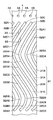
- FIG. 6 and FIG. 7 show a second embodiment.
- the feature of the second embodiment is that the flow path forming member is constituted by a plurality of members (partition walls).
- the same components as those in the first embodiment are denoted by the same reference numerals, and the description thereof is omitted.
- the flow path 31 of the second embodiment is also a meandering flow path having a portion extending in the circumferential direction, like the flow path 21 of the first embodiment.
- the flow path 31 of the second embodiment includes a plurality of, ie, four, flow paths 31A, 31B, 31C, and 31D extending around the circumference (obliquely) between the inner cylinder 4 and the electrode cylinder 17. It has become.
- Each of the flow paths 31A, 31B, 31C, 31D extends (obliquely) in a first circumferential direction (for example, a clockwise direction when viewed from the caulking portion 2A side of the outer cylinder 2) in one portion,
- the portion extends (obliquely) in a second circumferential direction opposite to the first circumferential direction (for example, a counterclockwise direction when viewed from the caulking portion 2A side of the outer cylinder 2).
- the fluid force flowing in the second circumferential flow path (obliquely) with respect to the fluid force flowing (obliquely) in the first circumferential flow path works in a direction that cancels out the working fluid 20 from the inside.
- the (total) rotational force (torque, moment) applied to the cylinder 4 and the electrode cylinder 17 can be reduced.
- the flow path 31 (31A, 31B, 31C, 31D) of the second embodiment is also a first circumferential direction that is a portion extending in the first circumferential direction, like the flow path 21 of the first embodiment.
- a clockwise path as a path, a counterclockwise path as a second circumferential path as a portion extending in the second circumferential direction, and a return path connecting the clockwise and counterclockwise paths It consists of In FIGS. 6 and 7, in order to avoid complication of the drawings, the reference numerals are omitted for the clockwise, counterclockwise, and return paths of the flow paths 31A, 31B, 31C, and 31D.
- the flow paths 31A, 31B, 31C, 31D are formed by four partition walls 32A, 32B, 32C, 32D as flow path forming members.
- the partition walls 32 ⁇ / b> A, 32 ⁇ / b> B, 32 ⁇ / b> C, and 32 ⁇ / b> D are provided between the inner cylinder 4 and the electrode cylinder 17.
- the partition walls 32A, 32B, 32C, 32D extend obliquely around the circumference between the inner cylinder 4 and the electrode cylinder 17, thereby causing the flow paths 31A, 31B, 31C to meander between the electrode cylinder 17 and the inner cylinder 4. , 31D are formed.
- the partition walls 32A, 32B, 32C, and 32D partition the flow paths 31A, 31B, 31C, and 31D between the inner cylinder 4 and the electrode cylinder 17, and are fixed to the inner cylinder 4 (into the inner cylinder 4). Integrated)).
- the partition walls 32A, 32B, 32C, 32D form flow paths 31A, 31B, 31C, 31D through which the working fluid 20 flows by the forward and backward movement of the piston rod 8 from the upper end side in the axial direction toward the lower end side. Yes.
- each partition wall 32A, 32B, 32C, 32D is, for example, the portion of the outer peripheral surface of the inner cylinder 4 that is out of the partition walls 32A, 32B, 32C, 32D and the inside of the electrode cylinder 17. It is set to be less than the distance from the peripheral surface.
- the working fluid 20 flowing through the four flow paths 31A, 31B, 31C, 31D is changed to the flow paths 31A, 31B, 31C, 31D adjacent in the circumferential direction. It does not flow out beyond each partition wall 32A, 32B, 32C, 32D.
- Each partition wall 32A, 32B, 32C, 32D is in the reverse direction before it goes around the circumference of the electrode cylinder 17 in the clockwise direction as shown in a development view in FIG.
- a curved line or straight line that folds counterclockwise on the contrary, a curved line or straight line that turns around counterclockwise around the electrode cylinder 17 in a counterclockwise direction). It diagonally extends in the first direction (for example, clockwise or counterclockwise), and in the other part, it is diagonally inclined in the second circumferential direction (for example, counterclockwise or clockwise) opposite to the first circumferential direction. It extends.
- each of the partition walls 32A, 32B, 32C, and 32D includes a first clockwise (clockwise) portion 32A1, 32B1, 32C1, and 32D1 that obliquely extends in the first circumferential direction and forms a first portion.
- Counterclockwise (counterclockwise) portions 32A2, 32B2, 32C2, and 32D2 that extend obliquely in the second circumferential direction opposite to the direction, and become one portion extending diagonally in the first circumferential direction. It has second clockwise (clockwise) portions 32A3, 32B3, 32C3 and 32D3.
- the clockwise (clockwise) and counterclockwise (counterclockwise) operation is when the electrode cylinder 17 (the shock absorber 1) is viewed from the upper end side (one end side) in the axial direction. This corresponds to the flow direction of the fluid 20.
- first clockwise portions 32A1, 32B1, 32C1, and 32D1 and the counterclockwise portions 32A2, 32B2, 32C2, and 32D2 are connected by first connecting portions (first folded portions) 32A4, 32B4, 32C4, and 32D4. Has been. Further, the counterclockwise portions 32A2, 32B2, 32C2, and 32D2 and the second clockwise portions 32A3, 32B3, 32C3, and 32D3 are connected by second connecting portions (second folded portions) 32A5, 32B5, 32C5, and 32D5. Has been.
- each of the partition walls 32A, 32B, 32C, and 32D includes the partition walls 32A, 32B, 32C, and 32D, and the inner cylinder 4 when the working fluid 20 flows along the partition walls 32A, 32B, 32C, and 32D.
- the moment (torque, rotational force) due to the shearing resistance acting on the electrode cylinder 17 is set to be canceled out.
- the first relative rotational force (for example, clockwise force) generated by the working fluid 20 flowing in the first circumferential direction and the first relative rotational force generated by the working fluid 20 flowing in the second circumferential direction are:
- the second relative rotational force (for example, counterclockwise force) in the reverse direction is brought close to the same magnitude.
- the shapes of the partition walls 32A, 32B, 32C, and 32D are set so that the first relative rotational force and the second relative rotational force are substantially the same.
- the axial lengths of the partition walls 32A, 32B, 32C and 32D in the two directions (clockwise and counterclockwise) need not be the same. For example, shorten the axial length in one direction (clockwise or counterclockwise) on the upstream side (upper end side) where pressure (shear resistance) is high (with a short flow path), and downstream side (lower end side) where pressure is low Thus, the axial length in the other direction (counterclockwise or clockwise) can be increased (long flow path).
- the length and the inclination (inclination amount) are set to a desired value (for example, the total is zero to zero) as the rotational force applied to the inner cylinder 4, the electrode cylinder 17 and the like from the working fluid 20 flowing through the flow path 31 (31A, 31B, 31C, 31D).
- a desired value for example, the total is zero to zero
- adjustment can be made based on experiments, simulations, calculation formulas, and the like.
- each of the partition walls 32A, 32B, 32C, and 32D can be formed of an insulator, for example, an electrically insulating polymer material (a resin material including a synthetic resin, a rubber material including a synthetic rubber, or the like).
- each of the partition walls 32A, 32B, 32C, and 32D is integrated by, for example, covering the outer peripheral surface of the inner cylinder 4 with a mold divided into four in the circumferential direction, and injection-molding a polymer material to the inner cylinder 4. Can be formed.
- the notch 33 is a part that connects a part of the flow paths 31A, 31B, 31C, and 31D that are adjacent to each other in the axial direction (adjacent positions) among the flow paths 31A, 31B, 31C, and 31D. Specifically, the notch 33 communicates between the flow path 31B and the flow path 31C adjacent in the axial direction and between the flow path 31C and the flow path 31D so that the working fluid 20 flows.
- the oil passage is formed.
- the notch 33 is provided only at a position corresponding to the upstream side of the flow path 31 in the partition walls 32C and 32D. Specifically, the notch 33 is provided in the first clockwise part 32C1 of the partition wall 32C and the first clockwise part 32D1 of the partition wall 32D.
- the notch 33 is formed as a groove extending in the axial direction by cutting the surfaces of the partition walls 32C and 32D. As a result, the working fluid 20 flows through the notch 33 between the adjacent flow paths 31B and 31C and between the flow paths 31C and 31D.
- the shock absorber 1 according to the second embodiment has the above-described configuration, and the operation thereof will be described next.
- the working fluid 20 that has flowed into the flow path 31 through the oil holes 4A (four oil holes 4A) of the inner cylinder 4 is between the partition walls 32A, 32B, 32C, and 32D between the inner cylinder 4 and the electrode cylinder 17.
- Flow paths 31A, 31B, 31C, 31D from the upper end side toward the lower end side.
- each of the partition walls 32A, 32B, 32C, 32D, the inner cylinder 4, and the electrode cylinder 17 has a rotational force (torque, torque) based on the shear resistance of the working fluid 20 flowing through the flow paths 31A, 31B, 31C, 31D.
- Moment the rotational force
- a notch 33 is provided in the partition wall 32C and the partition wall 32D.
- a part of working fluid which flows through the flow path 31B flows into the flow path 31C through the notch 33 provided in the partition wall 32C.
- a part of the working fluid flowing through the flow path 31C flows into the flow path 31D through the notch 33 provided in the partition wall 32D.
- the damping force characteristics of the shock absorber 1 are variously changed (adjusted) by changing at least one of the presence / absence of the notch 33, the number, position, size, cross-sectional shape, extending direction, and the like of the notch 33. Tuning). Thereby, a change and distinction (discrimination) of a damping force characteristic can be performed easily.
- the present invention is not limited thereto, and for example, a configuration in which a plurality of flow paths are provided by changing the shape of the ring-shaped member may be employed.
- the flow path 21 meanders has been described as an example.
- the present invention is not limited thereto, and for example, the flow path may be formed in a spiral shape so that the working fluid flows only in one direction (clockwise direction or counterclockwise direction). The same applies to the second embodiment.
- a notch may be provided on the downstream side.
- the notch may be provided on the entire flow path from the upstream side to the downstream side, or may be provided only on the downstream side. The same applies to the second embodiment.
- the present invention is not limited to this, and for example, one or two notches may be provided, or four or more may be provided.
- a plurality of cutouts may be provided in one clockwise part 22B or one counterclockwise part 22C.
- the thickness dimension (diameter direction dimension) and width dimension (circumferential direction dimension) of the plurality of notches may be provided differently.
- the position, number, dimensions, and the like of the notches can be appropriately set according to necessary performance (attenuation performance), manufacturing cost, specifications, and the like.
- the notch 23 extends in the axial direction
- the present invention is not limited to this.
- the notch may be configured to extend obliquely with respect to the axial direction (axial center line). Further, for example, the notch may be configured to extend in the circumferential direction. The same applies to the second embodiment.
- the present invention is not limited to this, and for example, a configuration in which a notch is provided in the column portion may be employed.
- the ring-shaped member 22 as the flow path forming member is made of an insulator.
- the present invention is not limited to this, and for example, the ring-shaped member may be composed of other than an insulator.
- the ring-shaped member may be composed of a conductor, a magnetic material, a non-magnetic material, and the like. The same applies to the second embodiment.
- the ring-shaped member 22 is fixed to the inner cylinder 4 by light press-fitting and adhesion.
- the present invention is not limited to this.
- the ring-shaped member is integrally formed by covering the outer peripheral surface of the inner cylinder with a mold divided into four in the circumferential direction and injection-molding a polymer material on the inner cylinder. It is good also as a structure.
- a positioning groove is provided on the outer peripheral surface of the inner cylinder by denting a portion to which the ring-shaped member is fixed from other portions, and a polymer material such as a thermosetting resin is provided in the positioning groove. It is good also as a structure which carries out injection molding.
- the notch 23 is formed by cutting (coining) the surface of the ring-shaped member 22
- the present invention is not limited to this.
- the notch may be formed by pressing the surface of the ring-shaped member. The same applies to the second embodiment.
- the case where the working fluid 20 is configured to flow from the upper end side in the axial direction toward the lower end side has been described as an example.
- a configuration that flows from the lower end side in the axial direction toward the upper end side a configuration that flows from the left end side (or right end side) in the axial direction toward the right end side (or left end side), and shaft It is good also as a structure which flows toward the other end side from the one end side of an axial direction, such as the structure which flows toward the rear end side (or front end side) from the front end side (or rear end side) of a direction.
- the second embodiment is a structure which flows toward the other end side from the one end side of an axial direction.
- both ends of the electrode cylinder 17 in the axial direction are held by the holding members 10 and 14
- the present invention is not limited to this.
- only one end of the electrode cylinder in the axial direction is held by the holding member (for example, only the holding member 10 on the upper end side is held, and the lower end side of the electrode cylinder 17 is the outlet of the working fluid 20. It is good also as a structure which makes it the opening which becomes.
- the second embodiment is good also as a structure which makes it the opening which becomes.
- the partition walls 32A, 32B, 32C, and 32D that restrict the directions of the flow paths 31A, 31B, 31C, and 31D are provided (fixed) on the outer periphery side of the inner cylinder 4 .
- the present invention is not limited to this, and for example, a configuration may be employed in which the partition wall is provided (fixed) on the electrode cylinder (the inner circumference side). Moreover, it is good also as a structure which provides (fixes) a partition in an outer cylinder.
- partition walls 32A, 32B, 32C, and 32D that regulate the directions of the flow paths 31A, 31B, 31C, and 31D are provided is described as an example.
- the present invention is not limited to this.
- two or three partition walls may be provided, or five or more partition walls may be provided.
- the number of the partition walls can be appropriately set according to required performance (attenuation performance), manufacturing cost, specifications, and the like.
- each of the partition walls 32A, 32B, 32C, and 32D covers, for example, the outer peripheral surface of the inner cylinder 4 with a mold divided into four in the circumferential direction, and a polymer material is injection molded to the inner cylinder 4.
- a configuration may be adopted in which a preformed partition is bonded to the inner cylinder.
- a positioning groove may be provided on the outer peripheral surface of the inner cylinder by denting a part to which the partition wall is bonded from other parts, and the partition wall is bonded to the positioning groove.
- a covering member provided in a protruding manner with a partition wall is formed in advance on a sheet-like (plate-like) member that can cover the outer peripheral side of the inner cylinder over the entire circumference, and the covering member is wound around the inner cylinder. Also good.
- the shock absorber 1 is configured to be arranged in the vertical direction.
- the present invention is not limited to this, and for example, it can be arranged in a desired direction according to the attachment object, for example, it can be inclined and arranged in a range that does not cause aeration.
- the working fluid 20 as the functional fluid is configured by an electrorheological fluid (ER fluid)
- the present invention is not limited to this, and the working fluid as the functional fluid may be configured using, for example, a magnetic fluid (MR fluid) whose properties change due to a magnetic field.
- MR fluid magnetic fluid
- the electrode cylinder 17 as a cylinder member is replaced with an electrode and used as a magnetic pole.
- the magnetic field may be variably controlled from the outside.
- the insulating holding members 10, 14 and the like can be formed of, for example, a nonmagnetic material.
- shock absorber 1 as a cylinder device is used in a four-wheeled vehicle
- shock absorbers used for motorcycles shock absorbers used for railway vehicles
- shock absorbers used for various mechanical devices including general industrial equipment shock absorbers used for buildings, etc.
- each embodiment is an exemplification, and needless to say, partial replacement or combination of the configurations shown in different embodiments is possible.
- the flow path forming member is configured to have a cutout that allows the adjacent portions in the axial direction of the flow path to communicate with each other.
- a cylinder device in which a flow path forming member with a notch is incorporated has a damping force characteristic with respect to a cylinder device that differs only in that the notch is not formed. Can be different.
- the cylinder device can also vary the damping force characteristics by varying the number of notches.
- the damping force characteristics of the cylinder device are variously changed (adjusted and tuned) by varying at least one of the presence / absence of notches, the number of notches, position, size, cross-sectional shape, extending direction, and the like. can do.
- visually determining (discriminating and distinguishing) differences in the number of notches, position, size, cross-sectional shape, extending direction, and the like is compared to, for example, visually determining the angular difference of the spiral member. Can be done easily. Thereby, parts management can be performed easily.
- the damping force characteristics can be variously changed by changing at least one of the number, position, size, cross-sectional shape, extending direction, and the like of the notches formed in the flow path forming member. it can. For this reason, it is possible to easily change (adjust) the damping force characteristics in various ways. Furthermore, after manufacturing a flow path forming member that is not provided with a notch, a notch is formed in the flow path forming member later so as to obtain a desired damping force characteristic, thereby various damping force characteristics. It can be changed (adjusted). For this reason, parts can be shared and mass production costs can be suppressed.
- the notch is provided only on the upstream side where the functional fluid of the flow path forming member flows.
- the damping force characteristic can be variously changed (adjusted) by a notch provided at a position where the pressure of the functional fluid is high. For this reason, for example, even if the number of notches or the like is not greatly changed (for example, the difference in the number of notches is one), the damping force characteristics can be made different. Thereby, the freedom degree of a change (adjustment) of a damping force characteristic can be improved (the range which can be changed can be enlarged).
- the flow path forming member is made of an insulator. For this reason, even if the flow path forming member is in contact with both the cylindrical member serving as the electrode cylinder and the inner cylinder, the cylindrical member and the inner cylinder can be electrically insulated.
- the notch is configured to extend in the axial direction.
- the functional fluid can be circulated in the axial direction in the notch. That is, the damping force characteristic can be variously changed (adjusted) by the notch that allows the functional fluid to flow linearly from one side to the other side in the axial direction.
- the damping force characteristics can be made different without greatly changing the number of notches or the like (for example, even if the difference in the number of notches is one). Thereby, the freedom degree of a change (adjustment) of a damping force characteristic can be improved (the range which can be changed can be enlarged).
- the cylinder device includes an inner cylinder in which a functional fluid whose fluid properties change due to an electric field or a magnetic field is sealed, a rod is inserted inside, and an outer cylinder that is provided as an electrode or a magnetic pole.
- a flow path forming member that forms one or a plurality of flow paths that flow toward the end side.
- the channel is a spiral or meandering channel having a portion extending in the circumferential direction.
- the flow path forming member is formed with a notch that communicates the axially adjacent portions of the flow path with each other.
- the notch is provided only on the upstream side of the flow path forming member where the functional fluid flows.
- the flow path forming member is formed of an insulator.
- the notch is formed to extend in the axial direction.
- 1 buffer (cylinder device), 2 outer cylinder, 4 inner cylinder, 8 piston rod (rod), 17 electrode cylinder (cylinder member), 20 working fluid (fluid, functional fluid), 21, 31 (31A, 31B, 31C, 31D) flow path, 21A clockwise route (part extending in the circumferential direction, site adjacent in the axial direction), 21B counterclockwise route (part extending in the circumferential direction, site adjacent in the axial direction), 22 ring-shaped member (Channel forming means), 23, 33 notches, 32A, 32B, 32C, 32D partition walls (channel forming means)
Landscapes
- Engineering & Computer Science (AREA)
- General Engineering & Computer Science (AREA)
- Mechanical Engineering (AREA)
- Physics & Mathematics (AREA)
- Electromagnetism (AREA)
- Fluid-Damping Devices (AREA)
Abstract
Description
以上の実施形態に基づくシリンダ装置としては、例えば以下に記載する態様のものがあげられる。第1の態様のシリンダ装置は、電界または磁界により流体の性状が変化する機能性流体が封入され、内部にロッドが挿入される内筒と、該内筒の外側に設けられ、電極または磁極として機能する筒部材と、前記内筒と前記筒部材との間に設けられた流路形成部材であって、前記ロッドの進退動により前記機能性流体が前記シリンダ装置の軸方向の一端側から他端側に向けて流動する一つまたは複数の流路を形成する流路形成部材と、を備える。前記流路は、周方向に延びる部分を有する螺旋状または蛇行する流路である。前記流路形成部材には、前記流路のうち前記軸方向に隣接した部位を互いに連通させる切欠きが形成される。
上記第2の態様によれば、第1の態様において、前記切欠きは、前記流路形成部材のうち、前記機能性流体が流動する上流側にのみ設けられる。
上記第3の態様によれば、第1または第2の態様において、前記流路形成部材は、絶縁体から形成される。
上記第4の態様によれば、第1ないし第3のいずれかの態様において、前記切欠きは、前記軸方向に延びて形成される。
Claims (4)
- シリンダ装置であって、
電界または磁界により流体の性状が変化する機能性流体が封入され、内部にロッドが挿入される内筒と、
該内筒の外側に設けられ、電極または磁極として機能する筒部材と、
前記内筒と前記筒部材との間に設けられた流路形成部材であって、前記ロッドの進退動により前記機能性流体が前記シリンダ装置の軸方向の一端側から他端側に向けて流動する一つまたは複数の流路を形成する流路形成部材と、
を備え、
前記流路は、周方向に延びる部分を有する螺旋状または蛇行する流路であり、
前記流路形成部材には、前記流路のうち前記軸方向に隣接した部位を互いに連通させる切欠きが形成された
シリンダ装置。 - 請求項1に記載のシリンダ装置であって、
前記切欠きは、前記流路形成部材のうち、前記機能性流体が流動する上流側にのみ設けられる
シリンダ装置。 - 請求項1または2に記載のシリンダ装置であって、
前記流路形成部材は、絶縁体から形成される
シリンダ装置。 - 請求項1ないし3のいずれかに記載のシリンダ装置であって、
前記切欠きは、前記軸方向に延びて形成される
シリンダ装置。
Priority Applications (5)
| Application Number | Priority Date | Filing Date | Title |
|---|---|---|---|
| CN201680019759.1A CN107429780A (zh) | 2015-09-30 | 2016-09-26 | 缸装置 |
| JP2017543224A JP6404484B2 (ja) | 2015-09-30 | 2016-09-26 | シリンダ装置 |
| US15/562,357 US20180051766A1 (en) | 2015-09-30 | 2016-09-26 | Cylinder device |
| DE112016001099.0T DE112016001099T5 (de) | 2015-09-30 | 2016-09-26 | Zylindervorrichtung |
| KR1020177026853A KR20180061085A (ko) | 2015-09-30 | 2016-09-26 | 실린더 장치 |
Applications Claiming Priority (2)
| Application Number | Priority Date | Filing Date | Title |
|---|---|---|---|
| JP2015-192850 | 2015-09-30 | ||
| JP2015192850 | 2015-09-30 |
Publications (1)
| Publication Number | Publication Date |
|---|---|
| WO2017057214A1 true WO2017057214A1 (ja) | 2017-04-06 |
Family
ID=58427396
Family Applications (1)
| Application Number | Title | Priority Date | Filing Date |
|---|---|---|---|
| PCT/JP2016/078156 Ceased WO2017057214A1 (ja) | 2015-09-30 | 2016-09-26 | シリンダ装置 |
Country Status (6)
| Country | Link |
|---|---|
| US (1) | US20180051766A1 (ja) |
| JP (1) | JP6404484B2 (ja) |
| KR (1) | KR20180061085A (ja) |
| CN (1) | CN107429780A (ja) |
| DE (1) | DE112016001099T5 (ja) |
| WO (1) | WO2017057214A1 (ja) |
Cited By (2)
| Publication number | Priority date | Publication date | Assignee | Title |
|---|---|---|---|---|
| WO2017146155A1 (ja) * | 2016-02-24 | 2017-08-31 | 日立オートモティブシステムズ株式会社 | シリンダ装置およびその製造方法 |
| US11073190B2 (en) * | 2016-12-26 | 2021-07-27 | Hitachi Astemo, Ltd. | Cylinder apparatus |
Families Citing this family (5)
| Publication number | Priority date | Publication date | Assignee | Title |
|---|---|---|---|---|
| WO2018180433A1 (ja) * | 2017-03-30 | 2018-10-04 | 日立オートモティブシステムズ株式会社 | シリンダ装置 |
| EP3809012B1 (en) * | 2019-10-18 | 2025-06-11 | Öhlins Racing AB | Front fork position-dependent damping for bicycles and motorcycles |
| US12410823B2 (en) * | 2021-09-30 | 2025-09-09 | Moshun, LLC | Dilatant fluid based object movement control mechanism |
| US11988264B2 (en) * | 2021-10-19 | 2024-05-21 | DRiV Automotive Inc. | Hydraulic damper with a baffle |
| US20250304206A1 (en) * | 2024-04-02 | 2025-10-02 | Sram, Llc | Bicycle front forks having features to distribute lubricant |
Citations (3)
| Publication number | Priority date | Publication date | Assignee | Title |
|---|---|---|---|---|
| JPS59107348U (ja) * | 1983-01-10 | 1984-07-19 | トヨタ自動車株式会社 | シヨツクアブソ−バ |
| JPH11506529A (ja) * | 1995-06-05 | 1999-06-08 | エニダイン・インコーポレーテッド | 調整可能なエネルギー吸収装置 |
| WO2014135183A1 (de) * | 2013-03-07 | 2014-09-12 | Fludicon Gmbh | Schwingungsdämpfer |
Family Cites Families (4)
| Publication number | Priority date | Publication date | Assignee | Title |
|---|---|---|---|---|
| CN2816483Y (zh) * | 2005-08-04 | 2006-09-13 | 浙江大学 | 微型汽车磁流变智能减振装置 |
| CN2828439Y (zh) * | 2005-10-24 | 2006-10-18 | 河北工业大学 | 电流变流体减振器 |
| CN103148159B (zh) * | 2013-03-18 | 2014-12-31 | 中国人民解放军装甲兵工程学院 | 复合式作动器及其控制方法 |
| CN203297501U (zh) * | 2013-05-13 | 2013-11-20 | 宁波南方减震器制造有限公司 | 双筒高压磁流变减震器 |
-
2016
- 2016-09-26 KR KR1020177026853A patent/KR20180061085A/ko not_active Withdrawn
- 2016-09-26 CN CN201680019759.1A patent/CN107429780A/zh active Pending
- 2016-09-26 JP JP2017543224A patent/JP6404484B2/ja not_active Expired - Fee Related
- 2016-09-26 US US15/562,357 patent/US20180051766A1/en not_active Abandoned
- 2016-09-26 DE DE112016001099.0T patent/DE112016001099T5/de not_active Withdrawn
- 2016-09-26 WO PCT/JP2016/078156 patent/WO2017057214A1/ja not_active Ceased
Patent Citations (3)
| Publication number | Priority date | Publication date | Assignee | Title |
|---|---|---|---|---|
| JPS59107348U (ja) * | 1983-01-10 | 1984-07-19 | トヨタ自動車株式会社 | シヨツクアブソ−バ |
| JPH11506529A (ja) * | 1995-06-05 | 1999-06-08 | エニダイン・インコーポレーテッド | 調整可能なエネルギー吸収装置 |
| WO2014135183A1 (de) * | 2013-03-07 | 2014-09-12 | Fludicon Gmbh | Schwingungsdämpfer |
Cited By (2)
| Publication number | Priority date | Publication date | Assignee | Title |
|---|---|---|---|---|
| WO2017146155A1 (ja) * | 2016-02-24 | 2017-08-31 | 日立オートモティブシステムズ株式会社 | シリンダ装置およびその製造方法 |
| US11073190B2 (en) * | 2016-12-26 | 2021-07-27 | Hitachi Astemo, Ltd. | Cylinder apparatus |
Also Published As
| Publication number | Publication date |
|---|---|
| JP6404484B2 (ja) | 2018-10-10 |
| JPWO2017057214A1 (ja) | 2017-12-21 |
| DE112016001099T5 (de) | 2017-11-30 |
| CN107429780A (zh) | 2017-12-01 |
| US20180051766A1 (en) | 2018-02-22 |
| KR20180061085A (ko) | 2018-06-07 |
Similar Documents
| Publication | Publication Date | Title |
|---|---|---|
| JP6404484B2 (ja) | シリンダ装置 | |
| CN113195932B (zh) | 具有单个外部控制阀的阻尼器 | |
| CN106460992B (zh) | 用于车辆减振器的可变半径弹簧盘 | |
| KR102294332B1 (ko) | 완충기 | |
| JP2017015244A (ja) | シリンダ装置 | |
| CN111971485B (zh) | 具有内部液压止动件的阻尼器 | |
| JP6368433B2 (ja) | シリンダ装置 | |
| CN110486406A (zh) | 液压阻尼器 | |
| JP6503510B2 (ja) | シリンダ装置およびその製造方法 | |
| CN102913587A (zh) | 磁流变减震器 | |
| JP6690019B2 (ja) | シリンダ装置 | |
| CN108027006A (zh) | 缓冲器 | |
| WO2017073218A1 (ja) | 緩衝器及び緩衝器の組立方法 | |
| JP6745978B2 (ja) | シリンダ装置 | |
| JP6986456B2 (ja) | シリンダ装置 | |
| WO2017002982A1 (ja) | シリンダ装置 | |
| JP2013170600A (ja) | 減衰力制御弁及びショックアブソーバ | |
| JP6892378B2 (ja) | シリンダ装置 | |
| JP6761897B2 (ja) | シリンダ装置 | |
| JP6869837B2 (ja) | シリンダ装置 | |
| JP2019007599A (ja) | シリンダ装置 | |
| JP2019007601A (ja) | シリンダ装置 |
Legal Events
| Date | Code | Title | Description |
|---|---|---|---|
| 121 | Ep: the epo has been informed by wipo that ep was designated in this application |
Ref document number: 16851385 Country of ref document: EP Kind code of ref document: A1 |
|
| ENP | Entry into the national phase |
Ref document number: 2017543224 Country of ref document: JP Kind code of ref document: A |
|
| ENP | Entry into the national phase |
Ref document number: 20177026853 Country of ref document: KR Kind code of ref document: A |
|
| WWE | Wipo information: entry into national phase |
Ref document number: 15562357 Country of ref document: US |
|
| WWE | Wipo information: entry into national phase |
Ref document number: 112016001099 Country of ref document: DE |
|
| 122 | Ep: pct application non-entry in european phase |
Ref document number: 16851385 Country of ref document: EP Kind code of ref document: A1 |