WO2017057012A1 - 非水電解液二次電池 - Google Patents
非水電解液二次電池 Download PDFInfo
- Publication number
- WO2017057012A1 WO2017057012A1 PCT/JP2016/077215 JP2016077215W WO2017057012A1 WO 2017057012 A1 WO2017057012 A1 WO 2017057012A1 JP 2016077215 W JP2016077215 W JP 2016077215W WO 2017057012 A1 WO2017057012 A1 WO 2017057012A1
- Authority
- WO
- WIPO (PCT)
- Prior art keywords
- positive electrode
- negative electrode
- secondary battery
- metal foil
- mixture layer
- Prior art date
- Legal status (The legal status is an assumption and is not a legal conclusion. Google has not performed a legal analysis and makes no representation as to the accuracy of the status listed.)
- Ceased
Links
Images




Classifications
-
- H—ELECTRICITY
- H01—ELECTRIC ELEMENTS
- H01M—PROCESSES OR MEANS, e.g. BATTERIES, FOR THE DIRECT CONVERSION OF CHEMICAL ENERGY INTO ELECTRICAL ENERGY
- H01M50/00—Constructional details or processes of manufacture of the non-active parts of electrochemical cells other than fuel cells, e.g. hybrid cells
- H01M50/50—Current conducting connections for cells or batteries
- H01M50/572—Means for preventing undesired use or discharge
- H01M50/584—Means for preventing undesired use or discharge for preventing incorrect connections inside or outside the batteries
-
- H—ELECTRICITY
- H01—ELECTRIC ELEMENTS
- H01M—PROCESSES OR MEANS, e.g. BATTERIES, FOR THE DIRECT CONVERSION OF CHEMICAL ENERGY INTO ELECTRICAL ENERGY
- H01M10/00—Secondary cells; Manufacture thereof
- H01M10/05—Accumulators with non-aqueous electrolyte
- H01M10/056—Accumulators with non-aqueous electrolyte characterised by the materials used as electrolytes, e.g. mixed inorganic/organic electrolytes
- H01M10/0564—Accumulators with non-aqueous electrolyte characterised by the materials used as electrolytes, e.g. mixed inorganic/organic electrolytes the electrolyte being constituted of organic materials only
- H01M10/0566—Liquid materials
-
- H—ELECTRICITY
- H01—ELECTRIC ELEMENTS
- H01M—PROCESSES OR MEANS, e.g. BATTERIES, FOR THE DIRECT CONVERSION OF CHEMICAL ENERGY INTO ELECTRICAL ENERGY
- H01M10/00—Secondary cells; Manufacture thereof
- H01M10/05—Accumulators with non-aqueous electrolyte
- H01M10/058—Construction or manufacture
-
- H—ELECTRICITY
- H01—ELECTRIC ELEMENTS
- H01M—PROCESSES OR MEANS, e.g. BATTERIES, FOR THE DIRECT CONVERSION OF CHEMICAL ENERGY INTO ELECTRICAL ENERGY
- H01M50/00—Constructional details or processes of manufacture of the non-active parts of electrochemical cells other than fuel cells, e.g. hybrid cells
- H01M50/50—Current conducting connections for cells or batteries
- H01M50/531—Electrode connections inside a battery casing
- H01M50/533—Electrode connections inside a battery casing characterised by the shape of the leads or tabs
-
- H—ELECTRICITY
- H01—ELECTRIC ELEMENTS
- H01M—PROCESSES OR MEANS, e.g. BATTERIES, FOR THE DIRECT CONVERSION OF CHEMICAL ENERGY INTO ELECTRICAL ENERGY
- H01M50/00—Constructional details or processes of manufacture of the non-active parts of electrochemical cells other than fuel cells, e.g. hybrid cells
- H01M50/50—Current conducting connections for cells or batteries
- H01M50/572—Means for preventing undesired use or discharge
- H01M50/584—Means for preventing undesired use or discharge for preventing incorrect connections inside or outside the batteries
- H01M50/59—Means for preventing undesired use or discharge for preventing incorrect connections inside or outside the batteries characterised by the protection means
-
- Y—GENERAL TAGGING OF NEW TECHNOLOGICAL DEVELOPMENTS; GENERAL TAGGING OF CROSS-SECTIONAL TECHNOLOGIES SPANNING OVER SEVERAL SECTIONS OF THE IPC; TECHNICAL SUBJECTS COVERED BY FORMER USPC CROSS-REFERENCE ART COLLECTIONS [XRACs] AND DIGESTS
- Y02—TECHNOLOGIES OR APPLICATIONS FOR MITIGATION OR ADAPTATION AGAINST CLIMATE CHANGE
- Y02E—REDUCTION OF GREENHOUSE GAS [GHG] EMISSIONS, RELATED TO ENERGY GENERATION, TRANSMISSION OR DISTRIBUTION
- Y02E60/00—Enabling technologies; Technologies with a potential or indirect contribution to GHG emissions mitigation
- Y02E60/10—Energy storage using batteries
-
- Y—GENERAL TAGGING OF NEW TECHNOLOGICAL DEVELOPMENTS; GENERAL TAGGING OF CROSS-SECTIONAL TECHNOLOGIES SPANNING OVER SEVERAL SECTIONS OF THE IPC; TECHNICAL SUBJECTS COVERED BY FORMER USPC CROSS-REFERENCE ART COLLECTIONS [XRACs] AND DIGESTS
- Y02—TECHNOLOGIES OR APPLICATIONS FOR MITIGATION OR ADAPTATION AGAINST CLIMATE CHANGE
- Y02P—CLIMATE CHANGE MITIGATION TECHNOLOGIES IN THE PRODUCTION OR PROCESSING OF GOODS
- Y02P70/00—Climate change mitigation technologies in the production process for final industrial or consumer products
- Y02P70/50—Manufacturing or production processes characterised by the final manufactured product
Definitions
- the present invention relates to a non-aqueous electrolyte secondary battery.
- Patent Document 1 proposes a technique for preventing a short circuit by preventing a cutting edge of a positive electrode lead from overlapping with a negative electrode active material coated portion in an electrode winding group of a cylindrical lithium ion battery.
- Patent Document 1 it is necessary to widen the uncut width of the portion of the base foil that is not used as a current collecting lead, and when the positive electrode mixture is rolled at a high density, the electrode is bent, The effect of being a method for increasing the mixture density is reduced.
- the present invention has been made in view of the above points, and the object of the present invention is to short-circuit the negative electrode due to the cutting edge of the positive electrode tab portion without widening the uncut width of the positive electrode metal foil.
- An object of the present invention is to provide a non-aqueous electrolyte secondary battery having a structure that can be prevented.
- the non-aqueous electrolyte secondary battery of the present invention that solves the above problems is a non-aqueous electrolyte secondary battery having an electrode group in which positive electrodes and negative electrodes are alternately arranged with a separator interposed therebetween and stacked.
- the positive electrode has a positive electrode base portion provided with a positive electrode mixture layer on both sides of the positive electrode metal foil, and a positive electrode tab portion protruding from the positive electrode base portion and exposing the positive electrode metal foil, the positive electrode tab portion
- the protective layer is provided in the base end part of this.
- FIG. 1 is an external perspective view of a prismatic secondary battery of Example 1.
- FIG. 5B is a sectional view taken along line BB in FIG. 5A. The figure which expands and shows the A section of FIG. 5A. The figure which expands and shows the B section of FIG. 5B. The figure which shows typically the process of forming a positive mix layer and a protective layer. The figure which shows typically the process of forming a positive electrode tab part.
- FIG. 6 is an external perspective view of a nonaqueous electrolyte secondary battery according to Example 2. The figure which expands and shows the A section of FIG.
- Non-aqueous electrolyte secondary batteries are required to increase the density of the active material mixture in order to improve the capacity density.
- coated to metal foil with a roll press apparatus is common.
- a metal foil not coated with an active material for current collection is applied to one end and an electrode coated with an active material mixture is applied to the other end.
- the portion where the active material is applied is strongly rolled, while the portion where the active material is not applied is weaker than that, so the difference in elongation of the metal foil occurs and the electrode is curved.
- the cutting edge of the positive electrode metal foil is isolated from the negative electrode through the separator, but there is a concern that if the lead part is bundled and bent for welding to a current collector component, the separator is damaged and a short circuit is caused. Is done. That is, in order to increase the density of the positive electrode mixture containing the positive electrode active material of the non-aqueous electrolyte secondary battery, the material is rolled with high strength, but the active material is applied to prevent the electrode from being bent in this process. When the structure that cuts away the metal foil part that is not used to leave the part that becomes the lead for current collection is adopted, the cutting edge of the metal foil lead is likely to cause burrs and returns due to stress during processing. There is a concern that a short circuit may occur between the negative electrode and the positive electrode due to the breakage of the separator.
- the nonaqueous electrolyte secondary battery of the present invention is provided with a protective layer at the base end portion of the positive electrode tab portion and in the region facing the adjacent negative electrode, and the positive electrode metal foil in the positive electrode tab portion is provided. It is possible to prevent the positive electrode and the negative electrode from being short-circuited through the burr.
- FIG. 1 is an external perspective view of a prismatic secondary battery of Example 1
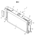
- FIG. 2 is an exploded perspective view showing a state where an electrode group is attached to a lid assembly.
- the nonaqueous electrolyte secondary battery of Example 1 to which the present invention is applied is a prismatic secondary battery 1, for example, a lithium ion secondary battery used as a power source for a hybrid vehicle or an electric vehicle.
- the prismatic secondary battery 1 includes a battery container including a prismatic battery can 2 that houses the electrode group 4 and a battery lid 3 that closes an opening of the battery can 2.
- the battery can 2 and the battery lid 3 are formed by subjecting a metal material such as aluminum or aluminum alloy to press working or the like.
- the battery can 2 has a rectangular box shape formed by deep drawing, and the battery lid 3 has a rectangular flat plate shape that closes the opening of the battery can 2.
- the battery lid 3 is welded to the battery can 2 to seal the opening.
- the positive external terminal 11 and the negative external terminal 21 are disposed at positions on both ends in the direction along the long side of the battery lid 3.
- a gas discharge valve 5 is disposed at a position near the center in the long side direction of the battery lid 3.
- a liquid injection hole 6 for injecting an electrolyte into the battery is disposed at a side position of the gas discharge valve 5.
- the liquid injection hole 6 is sealed by welding the liquid injection plug 7 to the battery lid 3 after injecting the electrolytic solution.
- the electrolytic solution for example, a non-aqueous electrolytic solution in which a lithium salt such as lithium hexafluorophosphate (LiPF6) is dissolved in a carbonic acid ester-based organic solvent such as ethylene carbonate can be used.
- the positive electrode current collector 12 and the negative electrode current collector 22 are fixed to the back side of the battery lid 3.
- the positive electrode current collector 12 is caulked and fixed to the battery lid 3 integrally with the positive electrode external terminal 11 by a positive electrode connection terminal penetrating the battery lid 3, and is electrically connected to the positive electrode external terminal 11.
- the negative electrode current collector 22 is caulked and fixed to the battery lid 3 integrally with the negative electrode external terminal 21 by a negative electrode connection terminal that penetrates the battery lid 3, and is electrically connected to the negative electrode external terminal 21.
- an insulating resin is provided between the positive electrode connecting terminal and the negative electrode connecting terminal and the battery lid 3 and between the positive electrode current collector 12 and the negative electrode current collector 22 and the battery lid 3, respectively. Is insulated.
- the positive electrode external terminal 11, the negative electrode external terminal 21, the positive electrode current collector 12, the negative electrode current collector 22 and the like are fixed to the battery cover 3 to form a cover assembly.
- the electrode group 4 is attached to the lid assembly.
- the electrode group 4 attached to the lid assembly is accommodated in the battery can 2 while being covered with an insulating case (not shown).
- the material of the insulating case is an insulating resin such as polypropylene.
- the electrode group 4 has a structure in which a positive electrode 31 and a negative electrode 41 are wound and laminated in a flat shape with a separator 51 interposed therebetween.
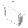
- a plurality of positive electrode tab portions 35 are disposed at one end of the electrode group 4 in the winding axis direction, and a negative electrode tab portion 45 is disposed at the other end portion.
- the positive electrode tab portion 35 and the negative electrode tab portion 45 are bundled at the center position in the thickness direction of the electrode group 4 and are integrally joined to the positive electrode current collector 12 and the negative electrode current collector 22 by ultrasonic welding, respectively.
- the positive electrode ribbon 13 and the negative electrode ribbon 23 are in contact with each other and welded together so that the positive electrode tab portion 35 and the negative electrode tab portion 45 are not torn by vibration due to ultrasonic waves.
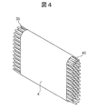
- the positive electrode tab portion 35 and the negative electrode tab portion 45 are provided only in the flat portion of the flat portion and the curved portion of the electrode group 4, but as in the other specific example shown in FIG. 4.
- the positive electrode tab portion 35 and the negative electrode tab portion 45 may be provided on both the flat portion and the curved portion of the electrode group 4 and bonded to the positive electrode current collector 12 and the negative electrode current collector 22, respectively.
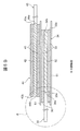
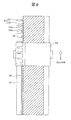
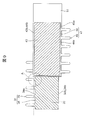
- FIG. 5A is a diagram for explaining the positional relationship between the positive electrode, the negative electrode, and the separator
- FIG. 5B is a cross-sectional view taken along the line BB in FIG. 5A
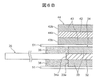
- FIG. 6A is an enlarged view of a portion A in FIG. 6B is an enlarged view of a portion B in FIG. 5B.
- the positive electrode 31 has a positive electrode base portion 34 provided with a positive electrode mixture layer 33 on both surfaces of a positive electrode metal foil 32 and a positive electrode tab portion 35 protruding from the positive electrode base portion 34 and exposing the positive electrode metal foil 32.
- the positive electrode base portion 34 has a strip shape having a long side and a short side, and a plurality of positive electrode tab portions 35 are provided at equal intervals on a long side 34 a on one side in the width direction of the positive electrode base portion 34. Yes.
- the edge 33a on one side in the width direction of the positive electrode mixture layer 33 is provided at a position spaced apart from the long side 34a of the positive electrode base portion 34 with a predetermined distance x1.
- the edge 33 b on the other side in the width direction is provided at the same position as the long side 34 b of the positive electrode base 34.
- the positive electrode tab portion 35 and the positive electrode base portion 34 are integrally provided. However, a configuration in which a separate member is provided later may be employed.
- the negative electrode 41 has a negative electrode base portion 44 provided with a negative electrode mixture layer 43 on both surfaces of the negative electrode metal foil 42 and a negative electrode tab portion 45 protruding from the negative electrode base portion 44 and exposing the negative electrode metal foil 42.
- the negative electrode base portion 44 has a strip shape having a long side and a short side, and the negative electrode tab portion 45 is provided with a plurality at equal intervals on a long side 44 a on one side in the width direction of the negative electrode base portion 44. Yes.
- An edge 43 b on one side in the width direction of the negative electrode mixture layer 43 is provided at the same position as the long side 44 b on one side in the width direction of the negative electrode base 44, and an edge on the other side in the width direction of the negative electrode mixture layer 43.
- 43 a is provided at a position spaced apart from the long side 44 a of the negative electrode base 44 with a predetermined interval.
- the positive electrode base 31 is formed so that the positive electrode base 34 is narrower than the negative electrode base 44 of the negative electrode 41.
- the pair of long sides 34 a and 34 b of the positive electrode base 34 is wider than the pair of long sides 44 a and 44 b of the negative electrode base 44. It arrange
- the positive electrode 31 is formed by cutting a portion other than the positive electrode tab portion 35 out of the positive electrode metal foil 32 protruding from the positive electrode mixture layer 33 to the vicinity of the positive electrode mixture layer 33. .
- the width x1 from the positive electrode mixture layer 33 to the long side 34a of the positive electrode base 34 is such that the position of the edge 43b of the negative electrode mixture layer 43 and the edge of the positive electrode mixture layer 33 on one side in the width direction of the electrode group 4 It is formed to be smaller than the distance difference x2 from the position 33a.
- the positive electrode metal foil 32 is made of an aluminum alloy foil having a thickness of about 20 to 30 ⁇ m
- the negative electrode metal foil 42 is made of a copper alloy foil having a thickness of about 15 to 20 ⁇ m.
- the positive electrode active material contained in the positive electrode mixture layer 33 is a lithium-containing transition metal double oxide such as lithium manganate, and the negative electrode active material contained in the negative electrode mixture layer 43 can reversibly store and release lithium ions.
- Carbon material such as graphite.
- the material of the separator 51 is a porous polyethylene resin.
- the positive electrode tab portion 35 protrudes from the long side 34 a of the positive electrode base portion 34 toward the outer side in the width direction of the positive electrode 31 with a substantially constant tab width.
- the positive electrode tab portion 35 is formed in an arc shape so that the tab width of the positive electrode tab portion 35 gradually decreases as it moves from the long side 34a of the positive electrode base portion 34 toward the distal end portion of the positive electrode tab portion 35.
- a straight portion 35b that is formed in a straight line toward the tip portion continuously from the R portion 35a.
- the R portion 35a of the positive electrode tab portion 35 is provided at a boundary portion between the positive electrode base portion 34 and the positive electrode base portion 34 in order to prevent the positive electrode tab portion 35 and the positive electrode tab portion 35 from being cut or broken.
- the R portion 35 a is disposed at a position overlapping the negative electrode mixture layer 43 of the negative electrode 41. As will be described later, when the positive electrode tab portion 35 is formed by cutting with a rotary cutter, burrs may occur at the cutting edge of the positive electrode metal foil 32, and burrs are most likely to occur at the R portion 35a.
- the R portion 35a is usually an end portion of the positive electrode metal foil 32 having a thickness of about 15 ⁇ m, and when a burr occurs during the formation of the positive electrode tab portion 35, for example, when bundled, it is a porous resin film having a thickness of about 30 ⁇ m. There is a possibility of causing a short circuit through the separator 51.
- the protective layer 36 is provided in a region facing the negative electrode 41 adjacent to the proximal end portion of the positive electrode tab portion 35.
- the protective layer 36 is provided with a width corresponding to at least the R portion 35 a of the positive electrode tab portion 35.
- the end portion of the protective layer 36 is wider than the end edge 43 b of the negative electrode mixture layer 43. It is provided so that it may be located outside.
- the protective layer 36 is formed, for example, by applying an insulating member on the positive electrode metal foil 32.
- the insulating member can be simply obtained by applying and drying a resin in which polyvinylidene fluoride is dissolved in NMP.
- the insulating member contains an inorganic filler such as alumina or an inorganic material having no conductivity such as lithium carbonate.
- the composition of the insulating member is not limited.
- the protective layer 36 has a predetermined thickness, and when a burr is generated in the positive electrode metal foil 32, the protruding height of the burr from the protective layer 36 can be reduced. Therefore, it is possible to prevent the burr of the positive electrode metal foil 32 of the R portion 35a from breaking through the separator and causing a short circuit.
- the protective layer 36 is positioned at the outer side in the width direction from the edge 33 a of the positive electrode mixture layer 33 to the base end of the positive electrode tab portion 35 and the edge 43 b of the negative electrode mixture layer 43 of the adjacent negative electrode 41. Up to a width x3.
- the coating width x3 of the protective layer 36 is preferably larger than the distance difference x2 between the side end position of the negative electrode mixture layer 43 and the side end position of the positive electrode mixture layer 33 on one side in the width direction of the electrode group 4.
- the protective layer 36 is provided also in the region between the edge 33a of the positive electrode mixture layer 33 and the long side 34a of the positive electrode base 34, when a burr occurs at the cutting edge of the long side 34a, the positive electrode mixture layer The protrusion height of the burr from 33 can be lowered. Therefore, it is possible to prevent the burr of the positive electrode metal foil 32 from breaking through the separator 51 and short-circuiting with the adjacent negative electrode 41.
- FIG. 7 is a diagram schematically showing the step of forming the positive electrode mixture layer and the protective layer
- FIG. 8 is a diagram schematically showing the step of forming the positive electrode tab portion.
- the method of forming the positive electrode 31 includes a step of applying a positive electrode mixture on both surfaces of the positive electrode metal foil 32 and a step of cutting one long side of the positive electrode metal foil 32 to form the positive electrode tab portion 35.
- an insulating member for forming the protective layer 36 is also applied at the same time.
- the manufacturing tact can be shortened by applying the insulating member simultaneously with the positive electrode mixture.
- the insulating member is applied by a die coater. For example, as shown in FIG. 7, the positive electrode material mixture 32 is moved in the coating direction by using a nozzle 62 for applying an insulating member separately from the nozzle 61 for applying the positive electrode material mixture. An insulating member is applied to a position adjacent to the substrate.
- the positive electrode tab portion 35 is formed by cutting an end portion on one side in the width direction of the positive electrode metal foil 32 using a rotary cutter 63 that rotates in the processing direction.
- the positive electrode tab portion 35 is formed on both ends of the coating portion, and rolling is performed in that state, thereby equalizing the left and right elongation in the winding direction and preventing the electrode from being bent.
- Example 2 will be described with reference to FIGS. 9 and 10.
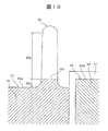
- FIG. 9 is an external perspective view of the non-aqueous electrolyte secondary battery according to Example 2, and FIG. 10 is an enlarged view of part A of FIG.
- the same components as those in the first embodiment are denoted by the same reference numerals, and detailed description thereof is omitted.
- the positive electrode mixture layer 33 of the positive electrode base portion 34 is extended to the base end portion of the positive electrode tab portion 35 and a region facing the adjacent negative electrode 41 to form a protective layer.
- the positive electrode mixture layer 33 is provided over the entire surface of the positive electrode base portion 34, and is also provided continuously at the base end portion of the positive electrode tab portion 35.
- the positive electrode mixture layer 33 at the base end portion of the positive electrode tab portion 35 is provided over a width corresponding to the R portion 35a and forms a protective layer.
- the positive electrode mixture layer 33 at the base end portion of the positive electrode tab portion 35 preferably covers the entire region facing the adjacent negative electrode 41, but is not limited to this configuration, and is most likely to generate burrs. It may be provided so as to cover only the width corresponding to the R portion 35a, which has the effect of reducing the possibility of a short circuit.
- the edge 33 c of the positive electrode mixture layer 33 in the positive electrode tab portion 35 is located on the inner side in the width direction of the positive electrode 31 than the edge 43 b of the negative electrode mixture layer 43.
- the positive electrode 31 and the negative electrode 41 are stacked on each other so that the edge 33 c of the positive electrode mixture layer 33 at the base end of the positive electrode tab portion 35 is located on the inner side in the width direction than the edge 43 b of the negative electrode mixture layer 43.
- the positive electrode mixture layer 33 provided at the base end portion of the positive electrode tab portion 35 has a predetermined thickness, and when burrs occur at the cutting edge of the positive electrode metal foil 32, The protrusion height of the burr can be lowered. Further, since the positive electrode mixture layer 33 is provided up to the long side 34a of the positive electrode base portion 34, when a burr is generated at the cutting edge of the long side 34a, the protrusion height of the burr from the positive electrode mixture layer 33 is increased. Can be lowered. Therefore, it is possible to prevent the burr of the positive electrode metal foil 32 from breaking through the separator 51 and short-circuiting with the adjacent negative electrode 41.
- the configuration is not limited to such a configuration.
- the pressure required for rolling the negative electrode 41 is increased. If there is no concern that the negative electrode 41 is curved even if it is small and does not have a shape in which such a plurality of negative electrode tab portions 45 are provided, there is no need to form such a plurality of negative electrode tab portions 45, and a constant width It is also possible to use a negative electrode metal foil as the current collector.
- the nonaqueous electrolyte secondary battery of the present invention is applied to the prismatic secondary battery 1 has been described as an example.
- the present invention is not limited to such a configuration.
- the present invention can also be applied to a cylindrical secondary battery having a cylindrical electrode group.
- the electrode group 4 is not limited to a wound type, and can be applied to a stacked type in which rectangular sheet-like positive electrodes and negative electrodes are alternately stacked.
- the case where the base portion of the positive electrode tab portion 35 has the R portion 35a has been described as an example. However, the provision of the R portion 35a is not essential, and the R portion 35a is not provided. May be.
- the present invention is not limited to the above-described embodiments, and various designs can be made without departing from the spirit of the present invention described in the claims. It can be changed.
- the above-described embodiment has been described in detail for easy understanding of the present invention, and is not necessarily limited to one having all the configurations described.
- a part of the configuration of an embodiment can be replaced with the configuration of another embodiment, and the configuration of another embodiment can be added to the configuration of an embodiment.
Landscapes
- Chemical & Material Sciences (AREA)
- Chemical Kinetics & Catalysis (AREA)
- Electrochemistry (AREA)
- General Chemical & Material Sciences (AREA)
- Manufacturing & Machinery (AREA)
- Engineering & Computer Science (AREA)
- Condensed Matter Physics & Semiconductors (AREA)
- General Physics & Mathematics (AREA)
- Inorganic Chemistry (AREA)
- Physics & Mathematics (AREA)
- Secondary Cells (AREA)
- Connection Of Batteries Or Terminals (AREA)
- Battery Electrode And Active Subsutance (AREA)
Abstract
本発明の課題は、正極金属箔の切り残し幅を広くすることなく、正極タブ部の切断エッジに起因した負極との短絡を防ぐことができる構造の非水電解液二次電池を得ることである。本発明の非水電解液二次電池(1)は、正極電極(31)と負極電極(41)を間にセパレータ(51)を介して交互に配置して積層された電極群(4)を有する。そして、正極電極(31)は、正極金属箔(32)の両面に正極合剤層(33)が設けられた正極基部(34)と、正極基部(34)から突出して正極金属箔(32)が露出する正極タブ部(35)とを有している。そして、正極タブ部(35)の基端部でかつ隣接する負極電極(41)と対向する領域に保護層(36)が設けられている。
Description
本発明は、非水電解液二次電池に関する。
特許文献1には、円筒型リチウムイオン電池の電極捲回群において、正極リードの切断エッジが負極活物質塗布部分と重ならないようにすることで短絡の防止を図る技術が提案されている。
しかしながら、特許文献1の技術では集電リードとして使用しない部分の基材箔の切り残し幅を広くする必要があり、正極合剤を高密度で圧延した場合には電極の湾曲が生じ、本来正極合剤密度を高くするための方法であるところの効果を減じるものとなっている。
本発明は、上記の点に鑑みてなされたものであり、その目的とするところは、正極金属箔の切り残し幅を広くすることなく、正極タブ部の切断エッジに起因した負極との短絡を防ぐことができる構造の非水電解液二次電池を提供することにある。
上記課題を解決する本発明の非水電解液二次電池は、正極電極と負極電極を間にセパレータを介して交互に配置して積層された電極群を有する非水電解液二次電池であって、前記正極電極は、正極金属箔の両面に正極合剤層が設けられた正極基部と、該正極基部から突出して前記正極金属箔が露出する正極タブ部とを有し、該正極タブ部の基端部に保護層が設けられていることを特徴とする。
本発明によれば、正極タブ部における正極金属箔のバリを介して正極電極と負極電極とが短絡するのを防ぐことができる。なお、上記した以外の課題、構成及び効果は、以下の実施形態の説明により明らかにされる。
以下、本発明の非水電解液二次電池を角形二次電池に適用した場合の実施の形態について、図面を参照して説明する。
非水電解液二次電池では、容量密度の向上のために活物質合剤の密度を高くすることが求められている。この密度を上げるために、金属箔に塗布された活物質合剤をロールプレス装置で圧延する工程が一般的である。このとき、捲回式の電極群を持つ電池であり、集電のために活物質が塗布されない金属箔が一端に、活物質合剤がもう一端に塗布されている電極の場合、強い線圧で圧延した場合は、活物質が塗布されている部分が強く圧延される一方で、塗布されていない部分はそれに比べて弱い圧延となるので金属箔の伸びに差が生じ、電極に湾曲が生じる。
これを回避するために、例えば、活物質が塗布されない金属箔部分を、集電タブとなる部分を残して切り取ることが提案されている。この場合、集電タブとして使用しない部分は活物質合剤の塗布境界最近傍まで切断し、金属箔の露出幅を極力少なくすることが、上記の湾曲回避のためには有効である。
一方で、一般に非水電解液二次電池では、正極のすべてが負極と対向するように電極を配置することで、充電時に正極から負極に移動するLiイオンが針状析出して短絡するなどの危険を回避している。上述のようにリードとして使用しない部分の金属箔の幅を狭くした構成の場合、正極活物質塗工部が全て負極活物質塗工部に対向するように配置すると、切り残したリードとして使用する部分の金属箔の切断エッジが負極活物質と対向する位置に配置されることになる。
正極金属箔の切断エッジは、セパレータを介して負極と隔絶されているが、集電部品への溶接等のためにリード部分を束ねて折り曲げる等した場合、セパレータを傷つけて短絡を引き起こすことが懸念される。すなわち、非水電解液二次電池の正極活物質材料を含む正極電極合剤の密度を上げるために高強度で圧延するが、かかる工程で電極が湾曲するのを防止するために活物質が塗布されない金属箔部分を集電のためのリードとなる部分を残して切り取る構成を採用した場合に、金属箔リードの切断エッジは、加工時の応力によりバリや返りが生じやすく、これを原因とするセパレータの破断により、負極と正極との間に短絡が起きることが懸念される。
これに対し、本発明の非水電解液二次電池は、正極タブ部の基端部でかつ隣接する負極電極と対向する領域に保護層が設けられており、正極タブ部における正極金属箔のバリを介して正極電極と負極電極とが短絡するのを防ぐことができる。
[実施例1]
図1は、実施例1の角形二次電池の外観斜視図、図2は、電極群を蓋組立体に取り付けた状態を示す分解斜視図である。
[実施例1]
図1は、実施例1の角形二次電池の外観斜視図、図2は、電極群を蓋組立体に取り付けた状態を示す分解斜視図である。
本発明が適用される実施例1の非水電解液二次電池は、角形二次電池1であり、例えばハイブリッド自動車や電気自動車等の動力源として用いられるリチウムイオン二次電池である。角形二次電池1は、電極群4を収容する角形の電池缶2と、電池缶2の開口部を閉塞する電池蓋3とからなる電池容器を有する。電池缶2および電池蓋3は、アルミニウムまたはアルミニウム合金などの金属材料にプレス加工等を施すことによって形成されている。電池缶2は、深絞り加工による角形の箱形状を有しており、電池蓋3は、電池缶2の開口部を塞ぐ長方形の平板形状を有している。電池蓋3は、電池缶2に溶接されて開口部を封口している。
電池蓋3の長辺に沿った方向の両端側の位置には、正極外部端子11および負極外部端子21が配設されている。電池蓋3の長辺方向中央寄りの位置には、ガス排出弁5が配設されている。そして、ガス排出弁5の側方位置には、電池内に電解液を注入するための注液孔6が配設されている。注液孔6は、電解液を注入した後に、注液栓7を電池蓋3に溶接することによって封止される。電解液としては、たとえば、エチレンカーボネート等の炭酸エステル系の有機溶媒に6フッ化リン酸リチウム(LiPF6)等のリチウム塩が溶解された非水電解液を用いることができる。
電池蓋3の裏面側には、正極集電体12及び負極集電体22が固定されている。正極集電体12は、電池蓋3を貫通する正極接続端子によって正極外部端子11と一体に電池蓋3にかしめ固定されており、正極外部端子11と電気的に接続されている。負極集電体22は、電池蓋3を貫通する負極接続端子によって負極外部端子21と一体に電池蓋3にかしめ固定されており、負極外部端子21と電気的に接続されている。
また、特に図示していないが、正極接続端子および負極接続端子と電池蓋3との間、および、正極集電体12および負極集電体22と電池蓋3との間には、それぞれ絶縁樹脂が介在されて絶縁されている。このように、電池蓋3に正極外部端子11および負極外部端子21、正極集電体12および負極集電体22等が固定されて蓋組立体が構成される。そして、この蓋組立体に電極群4が取り付けられている。
蓋組立体に取り付けられた電極群4は、絶縁ケース(図示せず)に覆われた状態で電池缶2に収容される。絶縁ケースの材質は、ポリプロピレン等の絶縁性を有する樹脂である。これにより、電池缶2の内面と、電極群4とは電気的に絶縁されている。
電極群4は、正極電極31と負極電極41とを、間にセパレータ51を介在させて扁平状に捲回して積層した構造を有している。電極群4の捲回軸方向一方側の端部には、複数の正極タブ部35が配置され、他方の端部に負極タブ部45が配置されている。正極タブ部35と負極タブ部45は、電極群4の厚さ方向中央位置に束ねられて、それぞれ超音波溶接によって正極集電体12と負極集電体22に一体に接合される。この際、正極タブ部35および負極タブ部45が超音波による振動で切裂しないように、正極リボン13と負極リボン23を当接してこれらと一体に溶接している。
図3に示す具体例では、電極群4の平坦部と湾曲部のうち、平坦部のみに正極タブ部35と負極タブ部45が設けられているが、図4に示す他の具体例のように、電極群4の平坦部と湾曲部の両方に正極タブ部35と負極タブ部45を設けて、それぞれ正極集電体12および負極集電体22に接合してもよい。
図5Aは、正極電極と負極電極とセパレータの位置関係を説明する図、図5Bは、図5AのB-B線断面図、図6Aは、図5AのA部を拡大して示す図、図6Bは、図5BのB部を拡大して示す図である。
正極電極31は、正極金属箔32の両面に正極合剤層33が設けられた正極基部34と、正極基部34から突出して正極金属箔32が露出する正極タブ部35を有している。正極基部34は、長辺と短辺を有する帯形状を有しており、正極タブ部35は、正極基部34の幅方向一方側の長辺34aにおいて複数が互いに等間隔をおいて設けられている。正極合剤層33の幅方向一方側の端縁33aは、正極基部34の長辺34aとの間に所定の距離x1を有して離れた位置に設けられており、正極合剤層33の幅方向他方側の端縁33bは、正極基部34の長辺34bと同じ位置に設けられている。なお、本実施例では、正極タブ部35と正極基部34とが一体に設けられているが、別体に設けたものを後で接続する構成としてもよい。
負極電極41は、負極金属箔42の両面に負極合剤層43が設けられた負極基部44と、負極基部44から突出して負極金属箔42が露出する負極タブ部45とを有している。負極基部44は、長辺と短辺を有する帯形状を有しており、負極タブ部45は、負極基部44の幅方向一方側の長辺44aにおいて複数が互いに等間隔をおいて設けられている。負極合剤層43の幅方向一方側の端縁43bは、負極基部44の幅方向一方側の長辺44bと同じ位置に設けられており、負極合剤層43の幅方向他方側の端縁43aは、負極基部44の長辺44aとの間に所定の間隔を有して離れた位置に設けられている。
正極電極31は、例えば図5Bに示すように、負極電極41の負極基部44よりも正極基部34の方が幅狭に形成されている。正極電極31と負極電極41は、セパレータ51を間に介して捲回された状態では、正極基部34の一対の長辺34a、34bが負極基部44の一対の長辺44a、44bよりもそれぞれ幅方向外側(捲回軸方向外側)の位置に配置される。
正極電極31は、図6Aに示すように、正極合剤層33から突出した正極金属箔32のうち、正極タブ部35以外の部分を正極合剤層33の近傍まで切除して形成されている。そして、正極合剤層33から正極基部34の長辺34aまでの幅x1が、電極群4の幅方向一方側における負極合剤層43の端縁43bの位置と正極合剤層33の端縁33aの位置との距離差x2よりも小さくなるように形成されている。
正極金属箔32は、厚さ20~30μm程度のアルミニウム合金箔により構成され、負極金属箔42は、厚さ15~20μm程度の銅合金箔により構成されている。正極合剤層33に含まれる正極活物質は、マンガン酸リチウム等のリチウム含有遷移金属複酸化物であり、負極合剤層43に含まれる負極活物質は、リチウムイオンを可逆に吸蔵、放出可能な黒鉛等の炭素材である。セパレータ51の素材は多孔質のポリエチレン樹脂である。
正極タブ部35は、図6Aに示すように、正極基部34の長辺34aから正極電極31の幅方向外側に向かって略一定のタブ幅で突出している。正極タブ部35は、正極基部34の長辺34aから正極タブ部35の先端部に向かって移行するにしたがって正極タブ部35のタブ幅が漸次狭くなるように円弧状に形成されたR部35aと、R部35aに連続して先端部に向かって直線状に形成された直線部35bを有している。正極タブ部35のR部35aは、正極基部34と正極タブ部35の切損および断裂を防止するために正極基部34との境界部に設けられている。
R部35aは、負極電極41の負極合剤層43と重なる位置に配置される。正極タブ部35は、後述するように、ロータリーカッターで切断して形成した場合、正極金属箔32の切断エッジにバリが発生するおそれがあり、R部35aにおいて最もバリが発生しやすい。R部35aは、通常15μm程度の正極金属箔32の端部であり、正極タブ部35の形成時にバリが生じた場合には、例えば束ねた際に、通常30μm程度の多孔質樹脂膜であるセパレータ51を貫通して短絡の原因となるおそれがある。
本実施例では、正極タブ部35の基端部でかつ隣接する負極電極41と対向する領域に保護層36を設けている。保護層36は、少なくとも正極タブ部35のR部35aに相当する幅に設けられており、本実施例では、保護層36の端部は、負極合剤層43の端縁43bよりも幅方向外側に位置するように設けられている。
保護層36は、例えば絶縁部材を正極金属箔32の上に塗布することによって形成される。絶縁部材は、ポリフッ化ビニリデンをNMPに溶解させた樹脂を塗布乾燥したものとするのが簡便であるが、アルミナ等の無機フィラーを含有したり、炭酸リチウム等の導電性のない無機物を含有させることも可能であり、絶縁部材の組成を限定するものではない。
保護層36は、所定の厚みを有しており、正極金属箔32にバリが発生した場合に、保護層36からのバリの突出高さを低くすることができる。したがって、R部35aの正極金属箔32のバリがセパレータを突き破って短絡するのを防止することができる。
本実施例では、正極タブ部35の基端部だけでなく、正極合剤層33の端縁33aから正極基部34の長辺34aとの間の領域にも絶縁部材を塗布して保護層36を設けている。すなわち、保護層36は、正極合剤層33の端縁33aから、正極タブ部35の基端部で且つ隣接する負極電極41の負極合剤層43の端縁43bよりも幅方向外側の位置までの幅x3に亘って設けられている。保護層36の塗布幅x3は、電極群4の幅方向一方側における負極合剤層43の側端位置と正極合剤層33の側端位置との距離差x2よりも大きくするのが好ましい。
正極合剤層33の端縁33aから正極基部34の長辺34aとの間の領域にも保護層36を設けることによって、長辺34aの切断エッジにバリが発生した場合に、正極合剤層33からのバリの突出高さを低くすることができる。したがって、正極金属箔32のバリがセパレータ51を突き破って隣接する負極電極41との間で短絡するのを防止することができる。
図7は、正極合剤層と保護層を形成する工程を模式的に示す図、図8は、正極タブ部を形成する工程を模式的に示す図である。
正極電極31を形成する方法は、正極金属箔32の両面に正極合剤を塗工する工程と、正極金属箔32の一方の長辺を切断して正極タブ部35を形成する工程を有する。
本実施例では、正極合剤を塗布する際に、同時に保護層36を形成するための絶縁部材の塗布も行う。このように正極合剤と同時に絶縁部材を塗布することで製造タクトを短縮することができる。絶縁部材の塗工はダイコーターで行われる。例えば図7に示すように、塗工方向に移動される正極金属箔32に対して、正極合剤を塗布するノズル61とは別に、絶縁部材を塗布するノズル62を使用して、正極合剤に隣接する位置に絶縁部材を塗布する。
そして、例えば図8に示すように、加工方向に回転するロータリーカッター63を用いて正極金属箔32の幅方向一方側の端部を切断することによって正極タブ部35を形成する。正極タブ部35の形成は、塗工部分両端に対して行い、その状態で圧延加工をすることにより、巻取り方向左右の伸びを均等化して電極の湾曲を防止する。
本実施例によれば、正極タブ部35の基端部でかつ隣接する負極電極41と対向する領域に保護層36を設けているので、正極金属箔32の切断エッジにバリが発生した場合に、バリがセパレータを突き破って負極電極41との間で短絡するのを防止することができる。
[実施例2]
次に、実施例2について図9および図10を用いて説明する。
[実施例2]
次に、実施例2について図9および図10を用いて説明する。
図9は、実施例2に係わる非水電解液二次電池の外観斜視図、図10は、図9のA部を拡大して示す図である。なお、実施例1と同様の構成要素には同一の符号を付することでその詳細な説明を省略する。
本実施例において特徴的なことは、正極基部34の正極合剤層33を正極タブ部35の基端部でかつ隣接する負極電極41と対向する領域まで延ばして保護層を構成したことである。
本実施例では、正極合剤層33は、正極基部34の全面に亘って設けられており、更に連続して正極タブ部35の基端部にも設けられている。正極タブ部35の基端部における正極合剤層33は、R部35aに相当する幅に亘って設けられており、保護層を形成している。正極タブ部35の基端部における正極合剤層33は、隣接する負極電極41と対向する領域の全てを覆うことが好ましいが、かかる構成に限定されるものではなく、最もバリが発生しやすいR部35aに相当する幅だけを覆うように設けてもよく、短絡の可能性を低減させるという効果を有する。
保護層は、正極タブ部35における正極合剤層33の端縁33cが負極合剤層43の端縁43bよりも正極電極31の幅方向内側に位置している。正極電極31と負極電極41は、正極タブ部35の基端部における正極合剤層33の端縁33cが負極合剤層43の端縁43bよりも幅方向内側に位置するように互いに積層配置されており、充電時に正極から負極に移動してくるLiイオンが固形析出しないようになっている。
正極タブ部35の基端部に設けられた正極合剤層33は、所定の厚みを有しており、正極金属箔32の切断エッジにバリが発生した場合に、正極合剤層33からのバリの突出高さを低くすることができる。また、正極合剤層33は、正極基部34の長辺34aまで設けられているので、長辺34aの切断エッジにバリが発生した場合に、正極合剤層33からのバリの突出高さを低くすることができる。したがって、正極金属箔32のバリがセパレータ51を突き破って隣接する負極電極41との間で短絡するのを防止することができる。
尚、上述の実施例1、2では、負極電極41が負極タブ部45を有する場合を例に説明したが、かかる構成に限定されるものではなく、例えば、負極電極41の圧延に要する圧力が小さく、このような複数の負極タブ部45を設けた形状でなくとも負極電極41が湾曲する懸念のない場合は、このような複数の負極タブ部45を形成する加工の必要はなく、一定幅の負極金属箔を以って集電部とする構成も可能である。
また、上述の実施例1、2では、本発明の非水電解液二次電池を角形二次電池1に適用した場合を例に説明したが、かかる構成に限定されるものではなく、例えば、円筒形の電極群を有する円筒形二次電池に適用することもできる。また、電極群4は、捲回式のものに限定されるものではなく、例えば矩形シート状の正極電極と負極電極を交互に重ね合わせて積層させた積層式のものに適用することもできる。また、上述の実施例1、2では、正極タブ部35の基端部にR部35aを有する場合を例に説明したが、R部35aを設けることは必須ではなく、R部35aを設けなくてもよい。
以上、本発明の実施形態について詳述したが、本発明は、前記の実施形態に限定されるものではなく、特許請求の範囲に記載された本発明の精神を逸脱しない範囲で、種々の設計変更を行うことができるものである。例えば、前記した実施の形態は本発明を分かりやすく説明するために詳細に説明したものであり、必ずしも説明した全ての構成を備えるものに限定されるものではない。また、ある実施形態の構成の一部を他の実施形態の構成に置き換えることが可能であり、また、ある実施形態の構成に他の実施形態の構成を加えることも可能である。さらに、各実施形態の構成の一部について、他の構成の追加・削除・置換をすることが可能である。
1 角形二次電池(非水電解液二次電池)
4 電極群
31 正極電極
32 正極金属箔
33 正極合剤層
33a、33b 端縁
34 正極基部
34a 長辺
35 正極タブ部
35a R部
36 保護層
41 負極電極
42 負極金属箔
43 負極合剤層
43a、43b 端縁
44 負極基部
44a 長辺
51 セパレータ
4 電極群
31 正極電極
32 正極金属箔
33 正極合剤層
33a、33b 端縁
34 正極基部
34a 長辺
35 正極タブ部
35a R部
36 保護層
41 負極電極
42 負極金属箔
43 負極合剤層
43a、43b 端縁
44 負極基部
44a 長辺
51 セパレータ
Claims (8)
- 正極電極と負極電極を間にセパレータを介して交互に配置して積層された電極群を有する非水電解液二次電池であって、
前記正極電極は、正極金属箔の両面に正極合剤層が設けられた正極基部と、該正極基部から突出して前記正極金属箔が露出する正極タブ部とを有し、該正極タブ部の基端部に保護層が設けられていることを特徴とする非水電解液二次電池。 - 前記正極基部と前記正極タブ部は一体に形成されていることを特徴とする請求項1に記載の非水電解液二次電池。
- 前記保護層は、少なくとも前記正極タブ部の基端部でかつ隣接する前記負極電極と対向する領域に設けられていることを特徴とする請求項2に記載の非水電解液二次電池。
- 前記保護層は、絶縁部材により構成されていることを特徴とする請求項3に記載の非水電解液二次電池。
- 前記保護層は、前記正極合剤層により構成されていることを特徴とする請求項3に記載の非水電解液二次電池。
- 前記絶縁部材と前記正極合剤層とは同じ工程で前記正極金属箔に塗布されることを特徴とする請求項4に記載の非水電解液二次電池。
- 前記正極タブ部は、前記正極基部との境界部にR部を有しており、
前記保護層は、少なくとも前記R部に相当する幅に設けられることを特徴とする請求項3に記載の非水電解液二次電池。 - 前記負極電極は、負極金属箔の両面に負極合剤層が設けられた負極基部と、該負極基部から突出して前記負極金属箔が露出する負極タブ部とを有し、
前記保護層は、前記正極合剤層の端縁が前記負極合剤層の端縁よりも前記正極電極の幅方向内側に位置することを特徴とする請求項5に記載の非水電解液二次電池。
Priority Applications (1)
| Application Number | Priority Date | Filing Date | Title |
|---|---|---|---|
| JP2017543116A JP6505859B2 (ja) | 2015-09-28 | 2016-09-15 | 非水電解液二次電池 |
Applications Claiming Priority (2)
| Application Number | Priority Date | Filing Date | Title |
|---|---|---|---|
| JP2015-190308 | 2015-09-28 | ||
| JP2015190308 | 2015-09-28 |
Publications (1)
| Publication Number | Publication Date |
|---|---|
| WO2017057012A1 true WO2017057012A1 (ja) | 2017-04-06 |
Family
ID=58427487
Family Applications (1)
| Application Number | Title | Priority Date | Filing Date |
|---|---|---|---|
| PCT/JP2016/077215 Ceased WO2017057012A1 (ja) | 2015-09-28 | 2016-09-15 | 非水電解液二次電池 |
Country Status (2)
| Country | Link |
|---|---|
| JP (1) | JP6505859B2 (ja) |
| WO (1) | WO2017057012A1 (ja) |
Cited By (19)
| Publication number | Priority date | Publication date | Assignee | Title |
|---|---|---|---|---|
| JP2017188371A (ja) * | 2016-04-08 | 2017-10-12 | リチウム エナジー アンド パワー ゲゼルシャフト ミット ベシュレンクテル ハフッング ウント コンパニー コマンディトゲゼルシャフトLithium Energy and Power GmbH & Co. KG | 蓄電素子 |
| WO2018066184A1 (ja) * | 2016-10-04 | 2018-04-12 | 株式会社村田製作所 | 電池、電動車両および蓄電システム |
| WO2018216644A1 (ja) * | 2017-05-26 | 2018-11-29 | 株式会社村田製作所 | 二次電池の製造方法 |
| JP2019021390A (ja) * | 2017-07-11 | 2019-02-07 | 株式会社豊田自動織機 | リチウムイオン二次電池 |
| JP2019102361A (ja) * | 2017-12-06 | 2019-06-24 | パナソニックIpマネジメント株式会社 | 電極板及び二次電池 |
| WO2020026483A1 (ja) * | 2018-07-30 | 2020-02-06 | パナソニックIpマネジメント株式会社 | リチウム二次電池 |
| JP2020191193A (ja) * | 2019-05-21 | 2020-11-26 | トヨタ自動車株式会社 | 非水電解質二次電池 |
| CN112970144A (zh) * | 2018-12-19 | 2021-06-15 | 三洋电机株式会社 | 二次电池用的电极板和使用了该电极板的二次电池 |
| KR20210082455A (ko) * | 2018-11-05 | 2021-07-05 | 테슬라, 인크. | 탭리스 전극을 구비한 전지 |
| JP2022074818A (ja) * | 2020-11-05 | 2022-05-18 | プライムプラネットエナジー&ソリューションズ株式会社 | 電池およびその製造方法 |
| US20230104632A1 (en) * | 2020-03-19 | 2023-04-06 | Sanyo Electric Co., Ltd. | Non-aqueous electrolyte secondary battery |
| JP2023066921A (ja) * | 2021-10-29 | 2023-05-16 | プライムプラネットエナジー&ソリューションズ株式会社 | 電池 |
| JP2024508700A (ja) * | 2021-02-18 | 2024-02-28 | 寧徳新能源科技有限公司 | 電気化学装置及び電子装置 |
| JP2024509242A (ja) * | 2021-03-18 | 2024-02-29 | 寧徳新能源科技有限公司 | 電気化学装置およびそれを応用した電気化学装置 |
| JP2024543226A (ja) * | 2021-12-01 | 2024-11-19 | エルジー エナジー ソリューション リミテッド | 抵抗が減少した円筒型電池 |
| JP2024167637A (ja) * | 2023-05-22 | 2024-12-04 | トヨタ自動車株式会社 | 蓄電セル |
| JP2025517718A (ja) * | 2022-07-20 | 2025-06-10 | エルジー エナジー ソリューション リミテッド | 電極組立体、バッテリー、それを含むバッテリーパック及び自動車 |
| JP2025537722A (ja) * | 2022-11-16 | 2025-11-20 | エルジー エナジー ソリューション リミテッド | 電極組立体および該電極組立体を含むバッテリー、並びに該バッテリーを含むバッテリーパックおよび自動車 |
| KR103002523B1 (ko) * | 2023-05-22 | 2026-08-11 | 도요타지도샤가부시키가이샤 | 축전 셀 |
Families Citing this family (4)
| Publication number | Priority date | Publication date | Assignee | Title |
|---|---|---|---|---|
| US11942661B2 (en) * | 2021-09-24 | 2024-03-26 | Apple Inc. | Battery cells with tabs at right angles |
| US11929522B2 (en) | 2021-09-24 | 2024-03-12 | Apple Inc. | Battery cells with tabs at right angles |
| US11870100B2 (en) | 2021-09-24 | 2024-01-09 | Apple Inc. | Battery cells with tabs at right angles |
| CN115020630B (zh) * | 2022-06-23 | 2024-06-25 | 三一技术装备有限公司 | 极片和极片单元的加工方法、极片、电池和极耳辊切装置 |
Citations (3)
| Publication number | Priority date | Publication date | Assignee | Title |
|---|---|---|---|---|
| JP2010080392A (ja) * | 2008-09-29 | 2010-04-08 | Toshiba Corp | 電池用電極及びその製造方法 |
| WO2013031891A1 (ja) * | 2011-08-31 | 2013-03-07 | Necエナジーデバイス株式会社 | 非水電解液二次電池 |
| JP2014238915A (ja) * | 2011-09-30 | 2014-12-18 | 三洋電機株式会社 | 積層式電池およびその製造方法 |
-
2016
- 2016-09-15 JP JP2017543116A patent/JP6505859B2/ja active Active
- 2016-09-15 WO PCT/JP2016/077215 patent/WO2017057012A1/ja not_active Ceased
Patent Citations (3)
| Publication number | Priority date | Publication date | Assignee | Title |
|---|---|---|---|---|
| JP2010080392A (ja) * | 2008-09-29 | 2010-04-08 | Toshiba Corp | 電池用電極及びその製造方法 |
| WO2013031891A1 (ja) * | 2011-08-31 | 2013-03-07 | Necエナジーデバイス株式会社 | 非水電解液二次電池 |
| JP2014238915A (ja) * | 2011-09-30 | 2014-12-18 | 三洋電機株式会社 | 積層式電池およびその製造方法 |
Cited By (44)
| Publication number | Priority date | Publication date | Assignee | Title |
|---|---|---|---|---|
| JP2017188371A (ja) * | 2016-04-08 | 2017-10-12 | リチウム エナジー アンド パワー ゲゼルシャフト ミット ベシュレンクテル ハフッング ウント コンパニー コマンディトゲゼルシャフトLithium Energy and Power GmbH & Co. KG | 蓄電素子 |
| JP2025061038A (ja) * | 2016-04-08 | 2025-04-10 | 株式会社Gsユアサ | 蓄電素子 |
| WO2018066184A1 (ja) * | 2016-10-04 | 2018-04-12 | 株式会社村田製作所 | 電池、電動車両および蓄電システム |
| JPWO2018066184A1 (ja) * | 2016-10-04 | 2019-03-22 | 株式会社村田製作所 | 電池、電動車両および蓄電システム |
| WO2018216644A1 (ja) * | 2017-05-26 | 2018-11-29 | 株式会社村田製作所 | 二次電池の製造方法 |
| JP2019021390A (ja) * | 2017-07-11 | 2019-02-07 | 株式会社豊田自動織機 | リチウムイオン二次電池 |
| JP7021466B2 (ja) | 2017-07-11 | 2022-02-17 | 株式会社豊田自動織機 | リチウムイオン二次電池 |
| JP7008247B2 (ja) | 2017-12-06 | 2022-02-10 | パナソニックIpマネジメント株式会社 | 電極板及び二次電池 |
| JP2019102361A (ja) * | 2017-12-06 | 2019-06-24 | パナソニックIpマネジメント株式会社 | 電極板及び二次電池 |
| US12334510B2 (en) | 2018-07-30 | 2025-06-17 | Panasonic Intellectual Property Management Co., Ltd. | Lithium secondary battery |
| CN112470323A (zh) * | 2018-07-30 | 2021-03-09 | 松下知识产权经营株式会社 | 锂二次电池 |
| JPWO2020026483A1 (ja) * | 2018-07-30 | 2021-08-02 | パナソニックIpマネジメント株式会社 | リチウム二次電池 |
| WO2020026483A1 (ja) * | 2018-07-30 | 2020-02-06 | パナソニックIpマネジメント株式会社 | リチウム二次電池 |
| JP7270142B2 (ja) | 2018-07-30 | 2023-05-10 | パナソニックIpマネジメント株式会社 | リチウム二次電池 |
| CN112470323B (zh) * | 2018-07-30 | 2024-02-23 | 松下知识产权经营株式会社 | 锂二次电池 |
| KR102836930B1 (ko) * | 2018-11-05 | 2025-07-22 | 테슬라, 인크. | 탭리스 전극을 구비한 전지 |
| US12463256B2 (en) | 2018-11-05 | 2025-11-04 | Tesla, Inc. | Cell with a tabless electrode |
| KR20210082455A (ko) * | 2018-11-05 | 2021-07-05 | 테슬라, 인크. | 탭리스 전극을 구비한 전지 |
| JP2022512776A (ja) * | 2018-11-05 | 2022-02-07 | テスラ,インコーポレイテッド | タブレス構造電極を有するセル |
| EP3878029A1 (en) * | 2018-11-05 | 2021-09-15 | Tesla, Inc. | A cell with a tabless electrode |
| JP7649736B2 (ja) | 2018-11-05 | 2025-03-21 | テスラ,インコーポレイテッド | タブレス構造電極を有するセル |
| US12548860B2 (en) | 2018-12-19 | 2026-02-10 | Sanyo Electric Co., Ltd. | Electrode plate for secondary cell, and secondary cell using same |
| CN112970144A (zh) * | 2018-12-19 | 2021-06-15 | 三洋电机株式会社 | 二次电池用的电极板和使用了该电极板的二次电池 |
| CN112970144B (zh) * | 2018-12-19 | 2023-11-17 | 三洋电机株式会社 | 二次电池用的电极板和使用了该电极板的二次电池 |
| JP7236030B2 (ja) | 2019-05-21 | 2023-03-09 | トヨタ自動車株式会社 | リチウムイオン二次電池 |
| JP2020191193A (ja) * | 2019-05-21 | 2020-11-26 | トヨタ自動車株式会社 | 非水電解質二次電池 |
| US20230104632A1 (en) * | 2020-03-19 | 2023-04-06 | Sanyo Electric Co., Ltd. | Non-aqueous electrolyte secondary battery |
| JP2022074818A (ja) * | 2020-11-05 | 2022-05-18 | プライムプラネットエナジー&ソリューションズ株式会社 | 電池およびその製造方法 |
| JP7154270B2 (ja) | 2020-11-05 | 2022-10-17 | プライムプラネットエナジー&ソリューションズ株式会社 | 電池およびその製造方法 |
| JP2024508700A (ja) * | 2021-02-18 | 2024-02-28 | 寧徳新能源科技有限公司 | 電気化学装置及び電子装置 |
| JP2025134800A (ja) * | 2021-02-18 | 2025-09-17 | 寧徳新能源科技有限公司 | 電気化学装置及び電子装置 |
| JP2025118799A (ja) * | 2021-03-18 | 2025-08-13 | 寧徳新能源科技有限公司 | 電気化学装置およびそれを応用した電気化学装置 |
| JP2024509242A (ja) * | 2021-03-18 | 2024-02-29 | 寧徳新能源科技有限公司 | 電気化学装置およびそれを応用した電気化学装置 |
| JP7897983B2 (ja) | 2021-03-18 | 2026-07-30 | 寧徳新能源科技有限公司 | 電気化学装置およびそれを応用した電気化学装置 |
| JP7679484B2 (ja) | 2021-03-18 | 2025-05-19 | 寧徳新能源科技有限公司 | 電気化学装置およびそれを応用した電気化学装置 |
| JP7385639B2 (ja) | 2021-10-29 | 2023-11-22 | プライムプラネットエナジー&ソリューションズ株式会社 | 電池 |
| JP2023066921A (ja) * | 2021-10-29 | 2023-05-16 | プライムプラネットエナジー&ソリューションズ株式会社 | 電池 |
| JP7810493B2 (ja) | 2021-12-01 | 2026-02-03 | エルジー エナジー ソリューション リミテッド | 抵抗が減少した円筒型電池 |
| JP2024543226A (ja) * | 2021-12-01 | 2024-11-19 | エルジー エナジー ソリューション リミテッド | 抵抗が減少した円筒型電池 |
| JP2025517718A (ja) * | 2022-07-20 | 2025-06-10 | エルジー エナジー ソリューション リミテッド | 電極組立体、バッテリー、それを含むバッテリーパック及び自動車 |
| JP7872376B2 (ja) | 2022-07-20 | 2026-06-09 | エルジー エナジー ソリューション リミテッド | 電極組立体、バッテリー、それを含むバッテリーパック及び自動車 |
| JP2025537722A (ja) * | 2022-11-16 | 2025-11-20 | エルジー エナジー ソリューション リミテッド | 電極組立体および該電極組立体を含むバッテリー、並びに該バッテリーを含むバッテリーパックおよび自動車 |
| JP2024167637A (ja) * | 2023-05-22 | 2024-12-04 | トヨタ自動車株式会社 | 蓄電セル |
| KR103002523B1 (ko) * | 2023-05-22 | 2026-08-11 | 도요타지도샤가부시키가이샤 | 축전 셀 |
Also Published As
| Publication number | Publication date |
|---|---|
| JPWO2017057012A1 (ja) | 2018-03-08 |
| JP6505859B2 (ja) | 2019-04-24 |
Similar Documents
| Publication | Publication Date | Title |
|---|---|---|
| JP6505859B2 (ja) | 非水電解液二次電池 | |
| KR101182904B1 (ko) | 전극 조립체와 이를 이용한 이차 전지 및 그 제조방법 | |
| JP5352612B2 (ja) | 二次電池 | |
| JP6735445B2 (ja) | 捲回型電池 | |
| JP5554181B2 (ja) | 非水電解質二次電池 | |
| KR102238367B1 (ko) | 전극 조립체 및 이를 포함하는 이차 전지 | |
| JP2002298825A (ja) | 電気化学デバイスの製造方法、および電気化学デバイス | |
| WO2017010046A1 (ja) | 捲回型電池 | |
| WO2017057762A1 (ja) | リチウムイオン二次電池の電極部、リチウムイオン二次電池及びリチウムイオン二次電池の製造方法 | |
| US20130157094A1 (en) | Secondary battery and method for producing the same | |
| US12548860B2 (en) | Electrode plate for secondary cell, and secondary cell using same | |
| CN111312935B (zh) | 电池 | |
| JP6322947B2 (ja) | 蓄電素子および極板 | |
| WO2020130001A1 (ja) | 二次電池用の電極板及びそれを用いた二次電池 | |
| US20150318535A1 (en) | Method for manufacturing stacked metal foil, method for manufacturing sealed cell including said method, and sealed cell | |
| JP2017098207A (ja) | 電極体を有する二次電池 | |
| JP4382431B2 (ja) | 非水電解質電池 | |
| US20170207494A1 (en) | Negative electrode plate, energy storage device, method for manufacturing negative electrode plate, and method for manufacturing energy storage device | |
| JP7043754B2 (ja) | リード部材および蓄電デバイス | |
| JP7600978B2 (ja) | 電池 | |
| KR101881237B1 (ko) | 축전 장치 및 축전 장치용 제조 방법 | |
| JP2012195122A (ja) | 非水電解液二次電池 | |
| KR20170114404A (ko) | 이차 전지 | |
| JP2016062770A (ja) | 蓄電素子および蓄電素子の製造方法 | |
| CN223181352U (zh) | 二次电池 |
Legal Events
| Date | Code | Title | Description |
|---|---|---|---|
| 121 | Ep: the epo has been informed by wipo that ep was designated in this application |
Ref document number: 16851186 Country of ref document: EP Kind code of ref document: A1 |
|
| ENP | Entry into the national phase |
Ref document number: 2017543116 Country of ref document: JP Kind code of ref document: A |
|
| NENP | Non-entry into the national phase |
Ref country code: DE |
|
| 122 | Ep: pct application non-entry in european phase |
Ref document number: 16851186 Country of ref document: EP Kind code of ref document: A1 |