WO2017056721A1 - 車載制御装置、および車載制御装置の情報更新システム - Google Patents
車載制御装置、および車載制御装置の情報更新システム Download PDFInfo
- Publication number
- WO2017056721A1 WO2017056721A1 PCT/JP2016/073025 JP2016073025W WO2017056721A1 WO 2017056721 A1 WO2017056721 A1 WO 2017056721A1 JP 2016073025 W JP2016073025 W JP 2016073025W WO 2017056721 A1 WO2017056721 A1 WO 2017056721A1
- Authority
- WO
- WIPO (PCT)
- Prior art keywords
- vehicle
- control device
- information
- vehicle control
- data server
- Prior art date
- Legal status (The legal status is an assumption and is not a legal conclusion. Google has not performed a legal analysis and makes no representation as to the accuracy of the status listed.)
- Ceased
Links
Images


Classifications
-
- H—ELECTRICITY
- H04—ELECTRIC COMMUNICATION TECHNIQUE
- H04L—TRANSMISSION OF DIGITAL INFORMATION, e.g. TELEGRAPHIC COMMUNICATION
- H04L67/00—Network arrangements or protocols for supporting network services or applications
- H04L67/34—Network arrangements or protocols for supporting network services or applications involving the movement of software or configuration parameters
-
- B—PERFORMING OPERATIONS; TRANSPORTING
- B60—VEHICLES IN GENERAL
- B60R—VEHICLES, VEHICLE FITTINGS, OR VEHICLE PARTS, NOT OTHERWISE PROVIDED FOR
- B60R16/00—Electric or fluid circuits specially adapted for vehicles and not otherwise provided for; Arrangement of elements of electric or fluid circuits specially adapted for vehicles and not otherwise provided for
- B60R16/02—Electric or fluid circuits specially adapted for vehicles and not otherwise provided for; Arrangement of elements of electric or fluid circuits specially adapted for vehicles and not otherwise provided for electric constitutive elements
- B60R16/023—Electric or fluid circuits specially adapted for vehicles and not otherwise provided for; Arrangement of elements of electric or fluid circuits specially adapted for vehicles and not otherwise provided for electric constitutive elements for transmission of signals between vehicle parts or subsystems
- B60R16/0231—Circuits relating to the driving or the functioning of the vehicle
-
- G—PHYSICS
- G06—COMPUTING OR CALCULATING; COUNTING
- G06F—ELECTRIC DIGITAL DATA PROCESSING
- G06F8/00—Arrangements for software engineering
- G06F8/60—Software deployment
- G06F8/65—Updates
-
- H—ELECTRICITY
- H04—ELECTRIC COMMUNICATION TECHNIQUE
- H04L—TRANSMISSION OF DIGITAL INFORMATION, e.g. TELEGRAPHIC COMMUNICATION
- H04L12/00—Data switching networks
- H04L12/02—Details
- H04L12/12—Arrangements for remote connection or disconnection of substations or of equipment thereof
-
- H—ELECTRICITY
- H04—ELECTRIC COMMUNICATION TECHNIQUE
- H04L—TRANSMISSION OF DIGITAL INFORMATION, e.g. TELEGRAPHIC COMMUNICATION
- H04L12/00—Data switching networks
- H04L12/28—Data switching networks characterised by path configuration, e.g. LAN [Local Area Networks] or WAN [Wide Area Networks]
- H04L12/40—Bus networks
- H04L12/40006—Architecture of a communication node
- H04L12/40039—Details regarding the setting of the power status of a node according to activity on the bus
-
- H—ELECTRICITY
- H04—ELECTRIC COMMUNICATION TECHNIQUE
- H04L—TRANSMISSION OF DIGITAL INFORMATION, e.g. TELEGRAPHIC COMMUNICATION
- H04L12/00—Data switching networks
- H04L12/28—Data switching networks characterised by path configuration, e.g. LAN [Local Area Networks] or WAN [Wide Area Networks]
- H04L12/40—Bus networks
- H04L2012/40267—Bus for use in transportation systems
- H04L2012/40273—Bus for use in transportation systems the transportation system being a vehicle
-
- Y—GENERAL TAGGING OF NEW TECHNOLOGICAL DEVELOPMENTS; GENERAL TAGGING OF CROSS-SECTIONAL TECHNOLOGIES SPANNING OVER SEVERAL SECTIONS OF THE IPC; TECHNICAL SUBJECTS COVERED BY FORMER USPC CROSS-REFERENCE ART COLLECTIONS [XRACs] AND DIGESTS
- Y02—TECHNOLOGIES OR APPLICATIONS FOR MITIGATION OR ADAPTATION AGAINST CLIMATE CHANGE
- Y02D—CLIMATE CHANGE MITIGATION TECHNOLOGIES IN INFORMATION AND COMMUNICATION TECHNOLOGIES [ICT], I.E. INFORMATION AND COMMUNICATION TECHNOLOGIES AIMING AT THE REDUCTION OF THEIR OWN ENERGY USE
- Y02D10/00—Energy efficient computing, e.g. low power processors, power management or thermal management
-
- Y—GENERAL TAGGING OF NEW TECHNOLOGICAL DEVELOPMENTS; GENERAL TAGGING OF CROSS-SECTIONAL TECHNOLOGIES SPANNING OVER SEVERAL SECTIONS OF THE IPC; TECHNICAL SUBJECTS COVERED BY FORMER USPC CROSS-REFERENCE ART COLLECTIONS [XRACs] AND DIGESTS
- Y02—TECHNOLOGIES OR APPLICATIONS FOR MITIGATION OR ADAPTATION AGAINST CLIMATE CHANGE
- Y02D—CLIMATE CHANGE MITIGATION TECHNOLOGIES IN INFORMATION AND COMMUNICATION TECHNOLOGIES [ICT], I.E. INFORMATION AND COMMUNICATION TECHNOLOGIES AIMING AT THE REDUCTION OF THEIR OWN ENERGY USE
- Y02D30/00—Reducing energy consumption in communication networks
- Y02D30/50—Reducing energy consumption in communication networks in wire-line communication networks, e.g. low power modes or reduced link rate
Definitions
- the present invention relates to an in-vehicle control device and an information update system for the in-vehicle control device.
- a data server managed by a vehicle manufacturer, a dealer, and the like and a vehicle under the management are connected by wireless communication, and the program and data of the in-vehicle control device of the update target vehicle are automatically updated according to an instruction from the data server.
- Patent Document 1 a method that enables efficient updating without bothering human hands has also been proposed.
- the data server identifies the update target vehicle and the in-vehicle control device and confirms whether the update is possible. It is necessary to keep it. This is because if a vehicle or an in-vehicle control device that is not a target is erroneously updated, the function of the vehicle may be lost, or in the worst case, the vehicle itself may not operate.
- Patent Document 1 as the means, a vehicle is woken up from a sleep state by an update request from a data server, an in-vehicle control device to be updated is selected by a reply from the waked-up vehicle, and a wake-up vehicle is A measure is taken to check whether the situation is updatable.
- the means of this document has a problem that the vehicle must be woken up to confirm whether there is an in-vehicle control device to be updated and whether the vehicle is in an updatable state, and the control becomes complicated. . Furthermore, since the document does not consider the remaining battery capacity of the vehicle, the amount of update information received from the data server is large, and the operation is performed when a large amount of power is consumed when data is received or updated. Information may not be updated normally due to insufficient power.
- the present invention has been made in order to solve the above-described problems, and includes a low power consumption mode in which the vehicle-mounted control device can only transmit and receive with a data server, and other vehicle-mounted control devices connected to the in-vehicle network.
- a low power consumption mode in which the vehicle-mounted control device can only transmit and receive with a data server, and other vehicle-mounted control devices connected to the in-vehicle network.
- the low power consumption mode even when the vehicle is parked, that is, when the ignition is OFF.
- If there is a vehicle response request from the data server it is determined whether the vehicle response request is addressed to the own vehicle in the low power consumption mode state. If the request is determined to be addressed to the own vehicle, an update permission response is sent to the data server. Transmit, and change its own mode to normal mode. The transition to the normal mode is performed only when there is a remaining battery level in which information can be written.
- the data server in the information update of the in-vehicle control device, can identify the target vehicle and the in-vehicle control device that are in an updatable state without waking up the parked vehicle.
- FIG. 11 It is a block diagram of the information update system which concerns on an Example. It is a figure which shows the example of the vehicle management data of the data server shown in FIG. It is a figure which shows the data communication sequence between the vehicle 1 and the data server 2 which concern on an Example. It is a figure which shows the mode transition of the vehicle-mounted control apparatus 11 by this invention. It is a figure which shows the example of a transmission message of the vehicle response request shown in FIG. It is a figure which shows the example of a response message with respect to the vehicle response request
- FIG. 11 It is a figure which shows the example of a communication sequence at the time of the vehicle-mounted control apparatus 11 by this invention collecting the management information of the own vehicle shown in FIG. It is a figure which shows the sequence in which the vehicle-mounted control apparatus 11 by this invention collects the information of a battery state.
- FIG. 1 is a configuration diagram of an information update system for an in-vehicle control device according to an embodiment of the present invention.
- the information update system of the present embodiment includes a vehicle 1 and a data server 2, which perform two-way wireless communication via the Internet line 3 and the base station 4. Although only one vehicle 1 is shown in FIG. 1, there are actually a plurality of vehicles 1 connected to a data server.
- Wireless communication is performed through, for example, a mobile phone network such as 3G / LTE or a line such as WiFi.
- the vehicle 1 includes an in-vehicle control device 11, other in-vehicle control devices a13 and b14, and a battery 12. These are connected to be able to perform data communication in both directions by an in-vehicle communication network 15 such as Controller Area Network (CAN), Local Interconnect Network (LIN).
- CAN Controller Area Network
- LIN Local Interconnect Network
- the in-vehicle control device 11 includes an out-vehicle communication unit 111, a write control unit 112, and an in-vehicle communication unit 113, and other in-vehicle control in which update information received from the data server 2 is connected to the own device and the in-vehicle communication network 15. It is distributed to the devices a13 and b14 and information is updated. Further, the outside-vehicle communication unit 111 includes a storage unit 1111, a determination unit 1112, a battery monitoring unit 1113, and a wireless antenna 1114.
- each component in the vehicle such as the in-vehicle control device is connected to the battery 12 by a power line and is supplied with power.
- the data server 2 includes a server 21 and a control unit 22.
- management information, user information, area information, etc. of a plurality of vehicles to be managed are registered in advance, and when an information update event occurs, a database is created for each vehicle so that the vehicle can be searched and extracted. Has been.
- the vehicle management data is information unique to each vehicle.
- the vehicle type and model, the management number for uniquely identifying the vehicle, the management number and software version of the in-vehicle control device mounted on each vehicle, the user information associated with the vehicle, Includes area information, update history information, etc.
- management data for one vehicle is described, but actually, the management data includes a plurality of vehicles managed by a data server.
- the data server 2 identifies the vehicle to be updated and the vehicle-mounted control device, and then distributes the update information to the identified vehicle. 11, information is updated to the other in-vehicle control device to be updated.
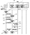
- FIG. 3 shows an outline of a data communication sequence for updating information between the vehicle 1 and the data server 2.
- a data server 2 an in-vehicle control device 11, other in-vehicle control devices a13, b14, and a battery.
- the vehicle-mounted control device 11, other vehicle-mounted control devices a13, b14, and a battery are included in the vehicle 1, and perform bidirectional communication with the data server 2 by radio.
- a program update of another vehicle-mounted control device a13 will be described as an example.
- the data server 2 searches for a vehicle to be updated based on the vehicle management data collectively managed by the server 21 (S302).
- the data server transmits a vehicle response request message to all the searched target vehicles (S303).
- the in-vehicle control device 11 that has received the vehicle response request message performs vehicle response determination processing (S304), and transmits a response message corresponding to the determination result to the data server (S305). Details of the vehicle response determination process (S304) will be described later.
- the data server 2 that has received the response message to the vehicle response request from the vehicle 1 (S305) checks the determination result included in the response message, and if the result is “specific success”, the data server 2 Then, the update program of the other in-vehicle control device a13 that is the update target is distributed (S306).
- the distributed update program is stored in the in-vehicle control device 11 (S307), and if it can be stored normally, the data server is notified of this (S308).
- the in-vehicle control device 11 transmits a Wakeup request via the in-vehicle communication network 15 in order to activate the other in-vehicle control device a13 that is an update target (S309).
- the other in-vehicle control device a13 that has received the Wakeup signal transmits a message to that effect to the in-vehicle control device 11 when the activation is completed (S310). Thereafter, the in-vehicle control device 11 updates the program of the other in-vehicle control device a13 (S311). If the program update is completed normally, the in-vehicle control device 11 notifies the data server 2 to that effect (S313). Finally, the in-vehicle control device 11 and the data server 2 update the management data (S314, S315).
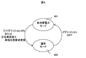
- FIG. 4 shows an operation mode provided in the in-vehicle control device 11 according to the present invention.
- the in-vehicle control device 11 has two operation modes. One is a low power consumption mode 401 in which only the communication unit outside the vehicle can operate, and the other is a normal mode 402 in which parts other than the communication unit outside the vehicle can also operate. When the ignition of the vehicle is turned off, the in-vehicle control device 11 transitions to the low power consumption mode 401 and can only communicate with the data server.
- the low power consumption mode when the ignition of the vehicle is turned on or when a vehicle response request addressed to the host vehicle is received, a transition to the normal mode 402 is made, in addition to communication with the data server, Communication with other in-vehicle control devices connected to the communication network 15 is also possible.
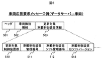
- FIG. 5 shows an example of a vehicle response request message transmitted from the data server 2 when an information update event occurs.
- the vehicle response request message includes a header 501, vehicle identification information 502, and update target in-vehicle control device information 503.
- the update target in-vehicle control device information 503 includes the number of update target control devices 510, the in-vehicle control device management number 511, the in-vehicle control device software management number 512, and the in-vehicle control device old software version 513.
- the update object vehicle-mounted control apparatus information 503 stores each vehicle-mounted control apparatus information in order, when there exist two or more update object vehicle-mounted control apparatuses.
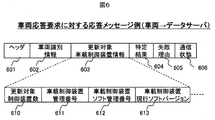
- FIG. 6 shows an example of a response message transmitted from the vehicle to the data server in response to the vehicle response request message.
- This response message includes a header 601, vehicle identification information 602, update target in-vehicle control device information 603, a specific result 604, a failure reason 605, and a communication state 606.
- the update target in-vehicle control device information 603 includes the number of update target control devices 610, the in-vehicle control device management number 611, the in-vehicle control device software management number 612, and the in-vehicle control device current software version 613.
- the determination result (“specific success” / “specific failure”) of the vehicle response determination process S304 in the in-vehicle control device 11 is stored in the specific result 604.
- the failure reason 605 stores the reason when the specific result is “failure”.
- the communication state 606 stores a radio wave state (strong / weak) received from the wireless antenna 1114 of the communication unit 111 outside the vehicle.
- the update target in-vehicle control device information 603 stores the respective in-vehicle control device information in order when there are a plurality of update target in-vehicle control devices.
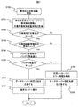
- FIG. 7 is an operation flow of vehicle response determination processing S304 executed when the in-vehicle control device 11 according to the present invention receives a vehicle response request from the data server.
- vehicle response determination processing S304 executed when the in-vehicle control device 11 according to the present invention receives a vehicle response request from the data server.
- Step S700 When receiving the vehicle response request from the data server 2, the outside-vehicle communication unit 111 of the in-vehicle control device 11 starts this flowchart and performs the vehicle response determination process S ⁇ b> 304.
- Step S701 The outside-vehicle communication unit 111 acquires the vehicle identification information 502 and the update target in-vehicle control device information 503 from the vehicle response request message received from the data server 2 via the wireless antenna 1114.
- Step S702 The outside-vehicle communication unit 111 compares the vehicle identification information 502 acquired in S701 with the in-vehicle identification information in the management information stored in advance in the storage unit 1111 in the determination unit 1112, and determines whether the request is directed to the own vehicle. Judging. As a result of the determination, if it is destined for the host vehicle, the process proceeds to step S702. If it is not addressed to the host vehicle, the process skips to step S708. Details of the management information stored in the storage unit 1111 will be described later.
- the outside-vehicle communication unit 111 uses the determination unit 1112 to store the in-vehicle control device management number 511, the in-vehicle control device software management number 512, and the in-vehicle control device old software version 513 stored in the update target in-vehicle control device information 503 acquired in S701. And the management number and software version of the in-vehicle control device information in the management information stored in advance in the storage unit 1111 are compared to determine whether the in-vehicle control device to be updated is correct. If the target in-vehicle control device is consistent as a result of the determination, the process proceeds to step S704. If not matched, the process skips to step S708. Details of the management information stored in the storage unit 1111 will be described later.
- the vehicle outside communication unit 111 acquires the state of the battery 12 in the battery monitoring unit 1113 and calculates the current remaining battery level (S704).
- the outside-vehicle communication unit 111 determines whether the calculated battery remaining capacity has a capacity necessary for downloading update information or updating (S705). As a result of the determination, if there is a remaining amount, the process proceeds to step S706. If there is no remaining amount, the process skips to step S708.
- the battery status acquisition process will be described later.
- the battery state acquisition process may be performed in advance before receiving the vehicle response request.
- Steps S706 to S707 The outside-vehicle communication unit 111 stores “success” in the response message identification result 604, and transmits the response message from the wireless antenna 1114 to the data server 2 (S706). Then, the mode of the outside-vehicle communication unit 111 is changed from the low power consumption mode to the normal mode (S707).
- a configuration example of the response message is shown in FIG.
- the outside-vehicle communication unit 111 stores “failure” and “reason for failure” in the response message specifying result 604 and the failure reason 605, respectively, and transmits a response from the wireless antenna 1114 to the data server (S709).
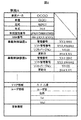
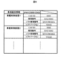
- FIG. 8 shows an example of the management information of the in-vehicle control device mounted on the host vehicle that the in-vehicle control device 11 according to the present invention stores in the storage unit 1111 of the outside-vehicle communication unit 111.
- the management information includes vehicle identification information that uniquely identifies the vehicle, an in-vehicle communication network ID (CAN ID in this case), a management number, a software management number, a software version, and the like of all the onboard control devices that are mounted.
- CAN ID in this case
- Pieces of management information may be stored in the storage unit 1111 when the vehicle is manufactured, or other in-vehicle control devices connected by the in-vehicle communication network 15 using the in-vehicle control device 11 as a trigger after the manufacture. In contrast, each piece of information may be collected in advance.
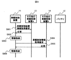
- FIG. 9 shows a sequence example when the in-vehicle control device 11 according to the present invention acquires management information of the in-vehicle control device of the own vehicle.
- the writing control unit 112 of the in-vehicle control device 11 transmits an in-vehicle control device information acquisition request to the other in-vehicle control device a13 via the in-vehicle communication unit 113 (S901).
- the other in-vehicle control device a13 receives the in-vehicle control device information acquisition request, it returns a response in which its own management information is set to the in-vehicle control device 11 (S902).
- the in-vehicle control device 11 stores the received data in the storage unit 1111 (S903).
- the write control unit 112 of the in-vehicle control device 11 transmits an in-vehicle control device information acquisition request to the other in-vehicle control device b14 via the in-vehicle communication unit 113 (S904).
- the other vehicle-mounted control device b14 receives the vehicle-mounted control device information acquisition request, it returns a response in which its own management information is set to the vehicle-mounted control device 11 (S905).
- the in-vehicle control device 11 stores the received data in the storage unit 1111 (S906).
- FIG. 10 shows a sequence example when the vehicle-mounted control device 11 according to the present invention collects or updates battery state information.
- the vehicle outside communication unit 111 of the in-vehicle control device 11 transmits a battery state acquisition request to the battery 12 by the battery monitoring unit 1113 (S1001).
- the battery 12 receives the battery state acquisition request, the battery 12 returns a response that sets the current battery state to the in-vehicle control device 11 (S1002).
- the vehicle-mounted control device 11 calculates the remaining battery level from the received battery state (S1003).
- the in-vehicle control device 11 receives the vehicle response request message from the data server in the low power consumption mode in which only the outside-vehicle communication unit 111 can operate, and is stored in the message.
- the vehicle identification information and in-vehicle control device information to be updated and the vehicle identification information and in-vehicle control device information stored in advance in the communication unit 111 outside the vehicle are checked, and the result is returned to the data server to wake up the vehicle. Therefore, it is possible to specify the vehicle to be updated and the presence or absence of the in-vehicle control device by a simple method. Further, by checking the remaining battery level with the same means, it is possible to avoid the possibility that update information can be normally received or cannot be updated due to a shortage of battery during information update.
- the vehicle response determination process has been described as being performed by the in-vehicle control device 11, but this can be realized even if the function is provided on the data server side.
- Vehicle 2 Data server 3: Internet line 4: Base station 11: In-vehicle control device 12: Battery 13: Other in-vehicle control device a 14: Other vehicle-mounted control device b 15: In-vehicle communication network 21: Server 22: Control unit 111: Outside-vehicle communication unit 112: Write control unit 113: In-vehicle communication unit 1111: Storage means 1112: Determination unit 1113: Battery monitoring unit 1114: Wireless antenna 401: Low Power consumption mode 402: Normal mode 501, 601: Header 502, 602: Vehicle identification information 503, 603: Update target in-vehicle control device information 510, 610: Number of update target control devices 511, 611: In-vehicle control device management number 512, 612 : Vehicle control device software management number 513: Vehicle control device old software version 604: Specific result 605: Reason for failure 606: Communication status 613: Current software version of vehicle control device
Landscapes
- Engineering & Computer Science (AREA)
- Signal Processing (AREA)
- Computer Networks & Wireless Communication (AREA)
- Theoretical Computer Science (AREA)
- Software Systems (AREA)
- General Engineering & Computer Science (AREA)
- Physics & Mathematics (AREA)
- General Physics & Mathematics (AREA)
- Computer Security & Cryptography (AREA)
- Automation & Control Theory (AREA)
- Mechanical Engineering (AREA)
- Stored Programmes (AREA)
- Information Transfer Between Computers (AREA)
- Devices For Checking Fares Or Tickets At Control Points (AREA)
- Traffic Control Systems (AREA)
- Electric Propulsion And Braking For Vehicles (AREA)
Abstract
Description
。また、失敗理由605には、特定結果が「失敗」であった場合の理由を格納する。また、通信状態606は、車両外通信部111の無線アンテナ1114から受信する電波状態(強弱)を格納する。なお、更新対象車載制御装置情報603は、更新対象の車載制御装置が複数ある場合、それぞれの車載制御装置情報を順番に格納する。
車載制御装置11の車両外通信部111は、データサーバ2から車両応答要求を受信すると、本フローチャートを開始して、車両応答判断処理S304を実施する。
車両外通信部111は、無線アンテナ1114を介し、データサーバ2から受信した車両応答要求メッセージから、車両識別情報502と更新対象車載制御装置情報503を取得する。
車両外通信部111は、判断部1112にて、S701で取得した車両識別情報502と、記憶手段1111にあらかじめ格納された管理情報の中の車載識別情報とを比較し、自車両宛ての要求かを判断する。判断の結果、自車両宛ての場合は、ステップS702へ進み。自車両宛てでない場合は、ステップS708へスキップする。なお、記憶手段1111に格納される管理情報の詳細は後述する。
車両外通信部111は、判断部1112にて、S701で取得した更新対象車載制御装置情報503に格納された車載制御装置管理番号511、車載制御装置ソフト管理番号512、車載制御装置旧ソフトバージョン513と、記憶手段1111にあらかじめ格納された管理情報の中の車載制御装置情報の管理番号やソフトバージョンを比較し、更新対象の車載制御装置が正しいかを判断する。判断の結果、対象車載制御装置の整合がとれている場合は、ステップS704へ進み。整合がとれていない場合は、ステップS708へスキップする。なお、記憶手段1111に格納される管理情報の詳細は後述する。
車両外通信部111は、バッテリ監視部1113にて、バッテリ12の状態を取得し、現在のバッテリ残量を算出する(S704)。車両外通信部111は、判断部1112にて、算出したバッテリ残量が、更新情報のダウンロードや、アップデートに必要な容量が残っているか判断する(S705)。判断の結果、残量がある場合は、ステップS706へ進み。残量がない場合は、ステップS708へスキップする。バッテリの状態の取得処理については、後述する。なお、バッテリの状態の取得処理は、車両応答要求を受信する前に事前に実施しておいても良い。
車両外通信部111は、「成功」を応答メッセージの特定結果604に格納し、無線アンテナ1114からデータサーバ2へ応答メッセージを送信する(S706)。そして、車両外通信部111のモードを低消費電力モードから通常モードへ遷移する(S707)。応答メッセージ構成例を図6に示す。
車両外通信部111は、「失敗」および「失敗理由」を応答メッセージの特定結果604と失敗理由605にそれぞれ格納し、無線アンテナ1114からデータサーバへ応答を送信する(S709)。
で構成される。
以上のように、本実施例に係る車載制御装置11は、車両外通信部111のみ動作可能な低消費電力モードで、データサーバからの車両応答要求メッセージを受信し、そのメッセージに格納されている更新対象の車両識別情報や車載制御装置情報と、車両外通信部111にあらかじめ記憶した車両識別情報や車載制御装置情報をチェックし、その結果をデータサーバへ応答することで、車両をウェイクアップすることなく、簡易な方法でアップデート対象の車両の特定や車載制御装置の有無の特定をすることができる。また、同様な手段において、バッテリ残量のチェックを行うことで、情報更新中のバッテリ不足により更新情報を正常に受信あるいは、更新できないおそれを未然に回避することができる。
本発明は上記した実施例に限定されるものではなく、様々な変形例が含まれる。上記実施例は、本発明を判りやすく説明するために詳細に説明したものであり、必ずしも説明した全ての構成を備えるものに限定されるものではない。
2:データサーバ
3:インターネット回線
4:基地局
11:車載制御装置
12:バッテリ
13:その他の車載制御装置a
14:その他の車載制御装置b
15:車両内通信ネットワーク
21:サーバ
22:制御部
111:車両外通信部
112:書込み制御部
113:車両内通信部
1111:記憶手段
1112:判断部
1113:バッテリ監視部
1114:無線アンテナ
401:低消費電力モード
402:通常モード
501,601:ヘッダ
502,602:車両識別情報
503,603:更新対象車載制御装置情報
510,610:更新対象制御装置数
511,611:車載制御装置管理番号
512,612:車載制御装置ソフト管理番号
513:車載制御装置旧ソフトバージョン
604:特定結果
605:失敗理由
606:通信状態
613:車載制御装置現行ソフトバージョン
Claims (17)
- 車両外のデータサーバと情報を送受信する車載制御装置であって、
前記データサーバとの送受信のみ可能な低消費電力モードと、その他の車載制御装置との通信も可能な通常モードを有し、
前記低消費電力モードにおいて、前記データサーバからの応答要求を受信した場合、前記応答要求が自車両宛ての応答要求であるかを判断し、
自車両宛ての応答要求と判断した場合、前記データサーバへ成功応答を送信し、前記通常モードへ遷移する
車載制御装置。 - 請求項1に記載の車載制御装置であって、
前記データサーバへの成功応答送信は、前記情報の書き込みが可能なバッテリ残量がある場合に行う
車載制御装置。 - 請求項1または2に記載の車載制御装置であって、
前記データサーバへの成功応答送信は、応答要求に格納される更新対象車載制御装置の管理情報と車載制御装置に記憶されるその他の車載制御装置の管理情報とが一致する場合に行う
車載制御装置。 - 請求項1乃至3のいずれかに記載の車載制御装置であって、
前記データサーバへ成功応答を送信し、前記通常モードへ遷移後、車両内通信ネットワークで接続された更新対象のその他の車載制御装置全てに対し、Wakeup要求を送信する
車載制御装置。 - 請求項1乃至4のいずれかに記載の車載制御装置であって、
前記データサーバへ送信される成功応答は、車両識別情報、車載制御装置の管理情報、判断結果のいずれかを含んでいる
車載制御装置。 - 請求項1乃至4のいずれかに記載の車載制御装置であって、
前記データサーバへ送信される失敗応答には、失敗理由を格納する
車載制御装置。 - 請求項1乃至4のいずれかに記載の車載制御装置であって、
前記自車両宛ての応答要求であるかの判断は、車両識別番号を用いる
車載制御装置。 - 請求項3に記載の車載制御装置であって、
前記その他の車載制御装置の管理情報は、あらかじめ車両内通信ネットワークで接続された他の車載制御装置から収集する
車載制御装置。 - 請求項1乃至8のいずれかに記載の車載制御装置であって、
前記データサーバから更新情報を正常に受信した場合、
当該車載制御装置自身、或いは、車両内通信ネットワークで接続されたその他の車載制御装置に対し、更新情報の書き込みを行う
車載制御装置。 - 請求項9に記載の車載制御装置であって、
前記更新情報の書き込みが正常に終了した場合、前記データサーバへ、更新が正常に完了した旨の通知を行う
車載制御装置。 - 請求項9または10に記載の車載制御装置であって、
前記更新情報の書き込みが正常に終了した場合、車両の電装装置を制御する
車載制御装置。 - 請求項1に記載の車載制御装置へ応答要求を送信する、車載制御装置の情報更新システムであって、
情報の更新イベントが発生した場合、データサーバから車両へ、車両識別情報を含む応答要求を送信し、
前記応答要求に対する前記車両からの応答に基づいて、前記情報の更新が可能な状態にある車両を特定する
車載制御装置の情報更新システム。 - 請求項12に記載の車載制御装置の情報更新システムであって、
データサーバは、特定のエリア情報と前記エリア情報が示すエリア内に在る車両の車両識別情報とを紐付けた車両管理データベースを有する
車載制御装置の情報更新システム。 - 請求項13に記載の車載制御装置の情報更新システムであって、
データサーバは、車両の車載制御装置の管理情報と車両の車両識別情報とを紐付けた車両管理データベースを有する
車載制御装置の情報更新システム。 - 請求項11乃至14のいずれかに記載の車載制御装置の情報更新システムであって、
前記応答要求に対する前記車両からの応答が成功応答であった場合、対象車両に対して更新情報の配信を実施する
車載制御装置の情報更新システム。 - 請求項11乃至15のいずれかに記載の車載制御装置の情報更新システムであって、
前記車両からの情報更新が正常に終了した旨の通知を受信したならば、前記データサーバは、前記車両管理データベースの当該車載制御装置の管理情報を最新の情報にアップデートする
車載制御装置の情報更新システム。 - 請求項11乃至16のいずれかに記載の車載制御装置の情報更新システムであって、
前記応答要求に対する前記車両からの応答の中に格納される無線通信状態が所定値以下の場合は、対象車両に対して更新情報の配信を行わない
車載制御装置の情報更新システム。
Priority Applications (4)
| Application Number | Priority Date | Filing Date | Title |
|---|---|---|---|
| DE112016004436.4T DE112016004436T5 (de) | 2015-09-29 | 2016-08-05 | Bordsteuerungsvorrichtung und Informationsaktualisierungssystemfür eine Bordsteuervorrichtung |
| US15/740,193 US10880404B2 (en) | 2015-09-29 | 2016-08-05 | On-vehicle control device and on-vehicle control device information update system |
| CN201680032669.6A CN108025684B (zh) | 2015-09-29 | 2016-08-05 | 车载控制装置以及车载控制装置的信息更新系统 |
| JP2017542987A JP6486484B2 (ja) | 2015-09-29 | 2016-08-05 | 車載制御装置、および車載制御装置の情報更新システム |
Applications Claiming Priority (2)
| Application Number | Priority Date | Filing Date | Title |
|---|---|---|---|
| JP2015190606 | 2015-09-29 | ||
| JP2015-190606 | 2015-09-29 |
Publications (1)
| Publication Number | Publication Date |
|---|---|
| WO2017056721A1 true WO2017056721A1 (ja) | 2017-04-06 |
Family
ID=58427359
Family Applications (1)
| Application Number | Title | Priority Date | Filing Date |
|---|---|---|---|
| PCT/JP2016/073025 Ceased WO2017056721A1 (ja) | 2015-09-29 | 2016-08-05 | 車載制御装置、および車載制御装置の情報更新システム |
Country Status (5)
| Country | Link |
|---|---|
| US (1) | US10880404B2 (ja) |
| JP (1) | JP6486484B2 (ja) |
| CN (1) | CN108025684B (ja) |
| DE (1) | DE112016004436T5 (ja) |
| WO (1) | WO2017056721A1 (ja) |
Cited By (5)
| Publication number | Priority date | Publication date | Assignee | Title |
|---|---|---|---|---|
| CN109005206A (zh) * | 2017-06-06 | 2018-12-14 | 通用汽车环球科技运作有限责任公司 | 用于通过无线进行车辆更新的处理器实施系统和方法 |
| JP2018202940A (ja) * | 2017-05-31 | 2018-12-27 | 株式会社アドヴィックス | ソフトウェア更新システム |
| CN112698851A (zh) * | 2019-10-07 | 2021-04-23 | 丰田自动车株式会社 | 程序更新系统、程序传送装置和程序传送方法 |
| JP2022157166A (ja) * | 2021-03-31 | 2022-10-14 | 三菱重工業株式会社 | 管理システム、管理方法、管理プログラム |
| JP2025065202A (ja) * | 2021-02-19 | 2025-04-17 | 日立Astemo株式会社 | 電池情報収集装置及び電池監視システム |
Families Citing this family (11)
| Publication number | Priority date | Publication date | Assignee | Title |
|---|---|---|---|---|
| US10140781B2 (en) * | 2009-04-15 | 2018-11-27 | Ford Global Technologies, Llc | Vehicle wireless information system |
| KR102123676B1 (ko) * | 2016-12-06 | 2020-06-29 | 주식회사 엘지화학 | 주택용 ESS에 탑재되는 직류변압기(DC-DC converter)와 배터리관리시스템(BMS) 소프트웨어의 통합관리 및 업데이트 방법 |
| US10416985B2 (en) * | 2017-02-16 | 2019-09-17 | Ford Global Technologies, Llc | Method and apparatus for multi cycle vehicle software update compliance handling |
| CN108810160A (zh) * | 2018-06-21 | 2018-11-13 | 珠海慧东方科技有限公司 | 一种平板电脑的系统更新方法及系统 |
| JP7003975B2 (ja) * | 2018-08-10 | 2022-01-21 | 株式会社デンソー | 車両情報通信システム,センター装置及びセンター装置のメッセージ送信方法 |
| JP7156192B2 (ja) * | 2018-08-10 | 2022-10-19 | 株式会社デンソー | 車両用マスタ装置、非書換え対象の電源管理方法及び非書換え対象の電源管理プログラム |
| KR102587084B1 (ko) | 2018-09-05 | 2023-10-11 | 현대자동차주식회사 | 차량의 업데이트 제공 장치 및 방법 |
| CN109532715A (zh) * | 2018-09-29 | 2019-03-29 | 上海博泰悦臻电子设备制造有限公司 | 车辆公用设置的同步方法、设置发起端及车辆 |
| JP7226047B2 (ja) * | 2019-04-09 | 2023-02-21 | 株式会社オートネットワーク技術研究所 | 車載コンピュータ、コンピュータ実行方法及びコンピュータプログラム |
| CN111935199B (zh) * | 2019-05-13 | 2023-07-25 | 广州汽车集团股份有限公司 | 一种车载软件版本信息同步方法、装置、系统及车辆 |
| JP7419287B2 (ja) * | 2021-03-26 | 2024-01-22 | 本田技研工業株式会社 | 車両プログラム更新管理システム、及び車両プログラム更新管理方法 |
Citations (3)
| Publication number | Priority date | Publication date | Assignee | Title |
|---|---|---|---|---|
| WO2005059862A1 (ja) * | 2003-12-15 | 2005-06-30 | Hitachi, Ltd. | 車載制御装置の情報更新方法と更新情報通信システム、および、車両搭載制御装置と情報管理基地局装置 |
| JP2009110529A (ja) * | 2008-11-14 | 2009-05-21 | Komatsu Ltd | 車載プログラムの書き換え制御システム |
| JP2011027962A (ja) * | 2009-07-24 | 2011-02-10 | Kyocera Mita Corp | 画像形成装置 |
Family Cites Families (16)
| Publication number | Priority date | Publication date | Assignee | Title |
|---|---|---|---|---|
| US6694235B2 (en) * | 2001-07-06 | 2004-02-17 | Denso Corporation | Vehicular relay device, in-vehicle communication system, failure diagnostic system, vehicle management device, server device and detection and diagnostic program |
| JP2004199490A (ja) * | 2002-12-19 | 2004-07-15 | Komatsu Ltd | 車載プログラムの書き換え制御装置 |
| JP2007011734A (ja) * | 2005-06-30 | 2007-01-18 | Denso Corp | 車載制御装置 |
| JP5138949B2 (ja) * | 2007-02-07 | 2013-02-06 | 日立オートモティブシステムズ株式会社 | 車載ゲートウェイ装置 |
| US8839356B2 (en) * | 2007-12-31 | 2014-09-16 | Intel Corporation | Methods and apparatuses for processing wake events of communication networks |
| JP5677811B2 (ja) * | 2010-06-11 | 2015-02-25 | 任天堂株式会社 | 携帯型情報端末、携帯情報システム、携帯型情報端末制御プログラム |
| US9543783B2 (en) * | 2011-04-12 | 2017-01-10 | Go-Tech Energy Co., Ltd. | Charging module and rechargeable battery assembly for electric vehicle |
| US9557981B2 (en) * | 2011-07-26 | 2017-01-31 | Ford Global Technologies, Llc | Method and apparatus for automatic module upgrade |
| KR101360705B1 (ko) * | 2011-09-22 | 2014-02-07 | 기아자동차주식회사 | 차량 업그레이드 시스템 및 그 방법 |
| JP5617875B2 (ja) * | 2012-08-10 | 2014-11-05 | 株式会社デンソー | 車載ネットワークシステム |
| US9858064B2 (en) * | 2012-08-16 | 2018-01-02 | Ford Global Technologies, Llc | Methods and apparatus for vehicle computing system software updates |
| KR20140066535A (ko) * | 2012-11-23 | 2014-06-02 | 삼성전자주식회사 | 전자 장치, 펌웨어 업데이트 방법 및 컴퓨터 판독가능 기록매체 |
| JP5900390B2 (ja) * | 2013-01-31 | 2016-04-06 | 株式会社オートネットワーク技術研究所 | アクセス制限装置、車載通信システム及び通信制限方法 |
| US9424047B2 (en) * | 2013-08-05 | 2016-08-23 | Harman International Industries, Incorporated | System and methods for an in-vehicle computing system |
| JP5975964B2 (ja) * | 2013-10-18 | 2016-08-23 | 富士通株式会社 | 情報処理プログラム、情報処理方法、情報処理装置、及び情報処理システム |
| DE102014008478B3 (de) * | 2014-06-07 | 2015-08-06 | Audi Ag | Fernsteuern eines Kraftfahrzeugs während einer Parkphase |
-
2016
- 2016-08-05 CN CN201680032669.6A patent/CN108025684B/zh active Active
- 2016-08-05 DE DE112016004436.4T patent/DE112016004436T5/de active Pending
- 2016-08-05 JP JP2017542987A patent/JP6486484B2/ja active Active
- 2016-08-05 WO PCT/JP2016/073025 patent/WO2017056721A1/ja not_active Ceased
- 2016-08-05 US US15/740,193 patent/US10880404B2/en active Active
Patent Citations (3)
| Publication number | Priority date | Publication date | Assignee | Title |
|---|---|---|---|---|
| WO2005059862A1 (ja) * | 2003-12-15 | 2005-06-30 | Hitachi, Ltd. | 車載制御装置の情報更新方法と更新情報通信システム、および、車両搭載制御装置と情報管理基地局装置 |
| JP2009110529A (ja) * | 2008-11-14 | 2009-05-21 | Komatsu Ltd | 車載プログラムの書き換え制御システム |
| JP2011027962A (ja) * | 2009-07-24 | 2011-02-10 | Kyocera Mita Corp | 画像形成装置 |
Cited By (7)
| Publication number | Priority date | Publication date | Assignee | Title |
|---|---|---|---|---|
| JP2018202940A (ja) * | 2017-05-31 | 2018-12-27 | 株式会社アドヴィックス | ソフトウェア更新システム |
| CN109005206A (zh) * | 2017-06-06 | 2018-12-14 | 通用汽车环球科技运作有限责任公司 | 用于通过无线进行车辆更新的处理器实施系统和方法 |
| CN112698851A (zh) * | 2019-10-07 | 2021-04-23 | 丰田自动车株式会社 | 程序更新系统、程序传送装置和程序传送方法 |
| CN112698851B (zh) * | 2019-10-07 | 2024-04-12 | 丰田自动车株式会社 | 程序更新系统、程序传送装置和程序传送方法 |
| JP2025065202A (ja) * | 2021-02-19 | 2025-04-17 | 日立Astemo株式会社 | 電池情報収集装置及び電池監視システム |
| JP2022157166A (ja) * | 2021-03-31 | 2022-10-14 | 三菱重工業株式会社 | 管理システム、管理方法、管理プログラム |
| JP7545924B2 (ja) | 2021-03-31 | 2024-09-05 | 三菱重工業株式会社 | 管理システム、管理方法、管理プログラム |
Also Published As
| Publication number | Publication date |
|---|---|
| DE112016004436T5 (de) | 2018-06-21 |
| US10880404B2 (en) | 2020-12-29 |
| CN108025684B (zh) | 2021-03-02 |
| JPWO2017056721A1 (ja) | 2018-05-24 |
| US20180191866A1 (en) | 2018-07-05 |
| JP6486484B2 (ja) | 2019-03-20 |
| CN108025684A (zh) | 2018-05-11 |
Similar Documents
| Publication | Publication Date | Title |
|---|---|---|
| JP6486484B2 (ja) | 車載制御装置、および車載制御装置の情報更新システム | |
| JP7852816B2 (ja) | プログラム更新システム、方法、およびプログラム | |
| US12030443B2 (en) | Vehicle electronic control system, distribution package download determination method and computer program product | |
| US9975504B2 (en) | Remote control of a motor vehicle during a parked phase | |
| US11467821B2 (en) | Vehicle master device, installation instruction determination method and computer program product | |
| US20210155176A1 (en) | Vehicle electronic control system, self-retention power execution control method and computer program product | |
| US20210167988A1 (en) | Vehicle master device, update data distribution control method, computer program product and data structure of specification data | |
| US20210405996A1 (en) | Server, managing method, non-transitory storage medium, software updating device, center, and over-the-air master | |
| CN110214308B (zh) | 控制装置、程序更新方法和计算机程序 | |
| US11928459B2 (en) | Electronic control unit, retry point specifying method and computer program product for specifying retry point | |
| CN111034132B (zh) | 控制设备、控制方法和计算机程序 | |
| CN104636150A (zh) | 车辆中软件的更新方法、系统和服务器 | |
| US11853742B2 (en) | Server, software update system, distribution method, and non-transitory storage medium | |
| CN110830267A (zh) | 网络节点的状态控制方法、装置及网关 | |
| CN114040360B (zh) | 服务器、更新管理方法、非临时存储介质、软件更新装置、带服务器及软件更新装置的系统 | |
| CN104951332A (zh) | 具有针对性的车辆远程特征更新 | |
| CN112165697B (zh) | Tbox休眠唤醒控制方法、装置及终端设备 | |
| WO2018079008A1 (ja) | 制御装置、プログラム更新方法、およびコンピュータプログラム | |
| JP2017157007A (ja) | プログラム更新システム、プログラム更新方法及びコンピュータプログラム | |
| JP2019159401A (ja) | 車両制御システム及び車両制御システムにおけるソフトウェアの整合性確認方法 | |
| US20210165644A1 (en) | Vehicle master device, rewrite target group administration method, computer program product and data structure of specification data | |
| JP2019105945A (ja) | 車載更新装置、プログラム及び、プログラム又はデータの更新方法 | |
| US11907697B2 (en) | Vehicle electronic control system, center device, vehicle master device, display control information transmission control method, display control information reception control method, display control information transmission control program, and display control information reception control program | |
| CN115904447A (zh) | 一种版本更新系统、方法、电子设备及存储介质 | |
| JP2016188017A (ja) | プログラム書換装置及びプログラム書換方法 |
Legal Events
| Date | Code | Title | Description |
|---|---|---|---|
| 121 | Ep: the epo has been informed by wipo that ep was designated in this application |
Ref document number: 16850898 Country of ref document: EP Kind code of ref document: A1 |
|
| ENP | Entry into the national phase |
Ref document number: 2017542987 Country of ref document: JP Kind code of ref document: A |
|
| WWE | Wipo information: entry into national phase |
Ref document number: 112016004436 Country of ref document: DE |
|
| 122 | Ep: pct application non-entry in european phase |
Ref document number: 16850898 Country of ref document: EP Kind code of ref document: A1 |