WO2017056519A1 - ロール及びその製造方法 - Google Patents
ロール及びその製造方法 Download PDFInfo
- Publication number
- WO2017056519A1 WO2017056519A1 PCT/JP2016/054701 JP2016054701W WO2017056519A1 WO 2017056519 A1 WO2017056519 A1 WO 2017056519A1 JP 2016054701 W JP2016054701 W JP 2016054701W WO 2017056519 A1 WO2017056519 A1 WO 2017056519A1
- Authority
- WO
- WIPO (PCT)
- Prior art keywords
- roll
- mass
- thermal spray
- roll body
- spray coating
- Prior art date
Links
Images
Classifications
-
- B—PERFORMING OPERATIONS; TRANSPORTING
- B21—MECHANICAL METAL-WORKING WITHOUT ESSENTIALLY REMOVING MATERIAL; PUNCHING METAL
- B21B—ROLLING OF METAL
- B21B27/00—Rolls, roll alloys or roll fabrication; Lubricating, cooling or heating rolls while in use
-
- B—PERFORMING OPERATIONS; TRANSPORTING
- B21—MECHANICAL METAL-WORKING WITHOUT ESSENTIALLY REMOVING MATERIAL; PUNCHING METAL
- B21B—ROLLING OF METAL
- B21B39/00—Arrangements for moving, supporting, or positioning work, or controlling its movement, combined with or arranged in, or specially adapted for use in connection with, metal-rolling mills
-
- C—CHEMISTRY; METALLURGY
- C23—COATING METALLIC MATERIAL; COATING MATERIAL WITH METALLIC MATERIAL; CHEMICAL SURFACE TREATMENT; DIFFUSION TREATMENT OF METALLIC MATERIAL; COATING BY VACUUM EVAPORATION, BY SPUTTERING, BY ION IMPLANTATION OR BY CHEMICAL VAPOUR DEPOSITION, IN GENERAL; INHIBITING CORROSION OF METALLIC MATERIAL OR INCRUSTATION IN GENERAL
- C23C—COATING METALLIC MATERIAL; COATING MATERIAL WITH METALLIC MATERIAL; SURFACE TREATMENT OF METALLIC MATERIAL BY DIFFUSION INTO THE SURFACE, BY CHEMICAL CONVERSION OR SUBSTITUTION; COATING BY VACUUM EVAPORATION, BY SPUTTERING, BY ION IMPLANTATION OR BY CHEMICAL VAPOUR DEPOSITION, IN GENERAL
- C23C4/00—Coating by spraying the coating material in the molten state, e.g. by flame, plasma or electric discharge
- C23C4/04—Coating by spraying the coating material in the molten state, e.g. by flame, plasma or electric discharge characterised by the coating material
-
- C—CHEMISTRY; METALLURGY
- C23—COATING METALLIC MATERIAL; COATING MATERIAL WITH METALLIC MATERIAL; CHEMICAL SURFACE TREATMENT; DIFFUSION TREATMENT OF METALLIC MATERIAL; COATING BY VACUUM EVAPORATION, BY SPUTTERING, BY ION IMPLANTATION OR BY CHEMICAL VAPOUR DEPOSITION, IN GENERAL; INHIBITING CORROSION OF METALLIC MATERIAL OR INCRUSTATION IN GENERAL
- C23C—COATING METALLIC MATERIAL; COATING MATERIAL WITH METALLIC MATERIAL; SURFACE TREATMENT OF METALLIC MATERIAL BY DIFFUSION INTO THE SURFACE, BY CHEMICAL CONVERSION OR SUBSTITUTION; COATING BY VACUUM EVAPORATION, BY SPUTTERING, BY ION IMPLANTATION OR BY CHEMICAL VAPOUR DEPOSITION, IN GENERAL
- C23C4/00—Coating by spraying the coating material in the molten state, e.g. by flame, plasma or electric discharge
- C23C4/18—After-treatment
Definitions
- the present invention relates to a roll suitable for transporting, for example, a steel plate and a manufacturing method thereof.
- the roll is used for lines such as steel plates, paper, synthetic resin sheets, for example, adamite rolls, alloy cast steel rolls, alloy chilled rolls.
- Anti-frouting roll, anti-tracking roll, applicator roll asu roll, backup roll, basket roll, bending roll, billy roll, block roll, breakdown roll, bridle roll, build-up roll, cage roll, carrier roll, cast steel Roll, centering roll, chilled roll, coating roll, composite roll, conductor roll, cradle roll, crown roll, dam roll, dancer roll, deflector roll, delivery Roll, Disc roll, Drive roll, Driven roll, Earth roll, Embossing roll, Entry roll, Exit roll, Fabricated roll, Finishing roll, Flap brush roll, Forged steel roll, Forming roll, Glen roll, Grinding roll, Guide roll, Gutter roll, Hearth roll, Herringbone roll, Hold down ball, Hollow roll, Horizontal roll, Idle roll, Intermediate roll, Intermediate mill roll, Caliber roll, Lateral adjust roll, Leveling roll, Lift roll, Lining roll , Looper roll, magnet roll, masher roll, measuring roll, metering roll, motor Roll, oiling roll, pass line roll, pickup roll,
- the present invention has been made in view of such circumstances, and provides a roll capable of extending the life compared to the prior art, suppressing the occurrence of wrinkles on an object in contact with the roll, and further preventing the same, and a method for manufacturing the roll. With the goal.
- the roll according to the first invention that meets the above-mentioned object is a roll having a roll body and support shafts that project on both sides of the roll body.
- the surface of the roll body that has been subjected to blasting treatment is subjected to shot blasting and has a surface roughness Ra in the range of 1 to 15 ⁇ m (more preferably 2.5 to 8 ⁇ m).
- the thermal spray coating includes 70 to 95% by mass of the thermal spray base material a, and 5 to 30% by mass of nickel powder as a blend material,
- the thermal spray base a includes 10 to 30% by mass of chromium carbide and 5 to 15% by mass of nickel, and 95% by mass or more of the balance is tungsten carbide.
- the roll according to the second invention that meets the above-mentioned object is a roll having a roll body and support shafts that project on both sides of the roll body.
- the surface of the roll body that has been subjected to blasting treatment is subjected to shot blasting and has a surface roughness Ra in the range of 1 to 15 ⁇ m (more preferably 2.5 to 8 ⁇ m).
- the thermal spray coating includes 70 to 95% by mass of the thermal spray base material a and 5 to 30% by mass of nickel chrome powder as a blend material,
- the thermal spray base a includes 10 to 30% by mass of chromium carbide and 5 to 15% by mass of nickel, and 95% by mass or more of the balance is tungsten carbide.
- the roll according to the third invention that meets the above-mentioned object is a roll having a roll main body and support shafts protruding on both sides of the roll main body.
- the surface of the roll body that has been subjected to blasting treatment is subjected to shot blasting and has a surface roughness Ra in the range of 1 to 15 ⁇ m (more preferably 2.5 to 8 ⁇ m).
- the thermal spray coating has a thermal spray base material b containing 5 to 25% by mass of cobalt and 95% by mass or more of the balance being tungsten carbide.
- the roll according to the fourth invention that meets the above-mentioned object is a roll having a roll body and support shafts protruding on both sides of the roll body.
- the surface of the roll body that has been subjected to blasting treatment is subjected to shot blasting and has a surface roughness Ra in the range of 1 to 15 ⁇ m (more preferably 2.5 to 8 ⁇ m).
- the thermal spray coating has a thermal spray base c containing 5 to 25 mass% of cobalt and chromium in total, and 95 mass% or more of the balance being tungsten carbide.
- a shot material containing alumina, steel, or glass beads is used for the shot blasting, and the particle size range of the shot material may be in the range of 38 to 425 ⁇ m. preferable.
- the roll has a roll body and support shafts projecting on both sides of the roll body.
- the surface of the roll body subjected to the blasting treatment includes 70 to 95% by mass of the thermal spray base material a and 5 to 30% by mass of nickel powder as a blend material, and the thermal spray base material a is carbonized.
- a second step of thermal spraying the coating material comprising 10 to 30% by mass of chromium and 5 to 15% by mass of nickel, and 95% by mass or more of the balance being tungsten carbide;
- the roll has a roll body and support shafts protruding on both sides of the roll body.
- a method for manufacturing a roll according to the third invention that meets the above-described object is a method for manufacturing a roll having a roll body and support shafts protruding on both sides of the roll body.
- the method for manufacturing a roll according to the fourth invention in accordance with the above object is a method for manufacturing a roll having a roll body and support shafts protruding on both sides of the roll body.
- the shot blasting process uses a projection material containing alumina, steel, or glass beads, and the particle size range of the projection material is in the range of 38 to 425 ⁇ m. It is preferable that it exists in.
- the roll body is made of metal, but the present invention is also applied to non-metal such as CFRP, for example.
- the surface roughness Ra is set to a range of 1 to 15 ⁇ m (more preferably 2.5 to 8 ⁇ m) by shot blasting on the surface of the roll body subjected to blasting. Since the sprayed coating of each composition is formed, it is possible to extend the life compared to the prior art by improving the wear resistance, and to suppress and further prevent generation of wrinkles on the object in contact with the roll.
- the surface roughness Ra of the sprayed coating is as described above. It can be easily adjusted in the range of 1 to 15 ⁇ m (more preferably 2.5 to 8 ⁇ m).
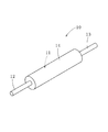
- a roll (hereinafter also simply referred to as a roll) 10 includes, for example, a metal roll body 11 and a support shaft that protrudes on both sides in the axial direction of the roll body 11. 12 and 13, and it is possible to extend the life compared to the conventional one by improving the wear resistance, and to suppress the occurrence of wrinkles on the steel plate (object in contact with the roll, here, an example of the conveyed product), Further, it can be prevented. This will be described in detail below.
- the roll 10 is installed in a cold rolling facility and conveys a steel plate.
- the usage of the roll is not limited to the conveyance of the steel plate.
- other metal plates for example, non-ferrous plates), strips, and the like, as well as resin plate materials (including films) and bar materials.
- the roll 10 has an axial length of the roll body 11 (body portion) of, for example, about 1000 to 1700 mm, a diameter of, for example, about 200 to 700 mm, and an axial total length including the support shafts 12 and 13.
- the thickness is about 1500 to 2500 mm.
- the dimension of a roll can be variously changed with a use application, and is not specifically limited.
- the roll body 11 is hollow, but may be solid. Further, the support shafts 12 and 13 are attached to the roll body 11 by shrink fitting, but the invention is not limited to this, and the roll body and the support shaft are integrally cut out from the metal lump. You can also.
- steel materials such as bearing steel (symbol: SUJ) having wear resistance can be used, but various changes can be made depending on the intended use, for example, high hardness steel, low carbon steel, etc. Can also be used, and Al (aluminum), Al alloy, Cu (copper), Cu alloy, etc. can also be used. Also good.
- the surface of the roll body 11 is blasted (roughened).
- This blasting process is a process performed to improve the adhesion between the roll body 11 and the thermal spray coating 14 formed on the surface thereof, and can be performed by, for example, sandblasting using a lump of metal, sand, or the like.
- the surface roughness Ra of the roll body 11 by the blasting process is not particularly limited, and can be appropriately set in consideration of the adhesion between the roll body 11 and the thermal spray coating 14.
- a sprayed coating 14 having a surface roughness Ra in the range of 1 to 15 ⁇ m (more preferably 2.5 to 8 ⁇ m) is formed on the surface of the roll body 11 subjected to the blasting treatment.
- the thickness (film thickness) of the thermal spray coating 14 is not particularly limited, but is preferably formed densely (with a filling rate of 90% or more, more preferably 95% or more) in the range of 20 to 100 ⁇ m, for example.
- the thickness of the sprayed coating is less than 20 ⁇ m, the thickness of the sprayed coating may be too thin to extend the life of the roll.
- the thickness of the sprayed coating 14 to be formed is preferably 20 to 100 ⁇ m, but the lower limit is preferably 40 ⁇ m, more preferably 60 ⁇ m, and the upper limit is more preferably 80 ⁇ m.
- the component composition of the thermal spray coating 14 is as shown in the following (1) to (4).
- the thermal spray coating A includes 70 to 95% by mass of the thermal spray base material a and 5 to 30% by mass of nickel powder (Ni powder) as a blend material. It contains 10 to 30% by mass of (Cr 3 C 2 ), 5 to 15% by mass of nickel (Ni), and the balance is tungsten carbide (WC).
- the thermal spray coating B includes 70 to 95% by mass of the thermal spray base material a and 5 to 30% by mass of nickel chrome powder (Ni—Cr powder) as a blend material.
- the thermal spray coating C has a thermal spray base material b containing 5 to 25% by mass of cobalt (Co) and the balance being tungsten carbide (WC).
- the thermal spray coating D has a thermal spray base c containing 5 to 25 mass% of cobalt (Co) and chromium (Cr) in total, and the balance being tungsten carbide (WC).
- the thermal spray coating A is composed of a granular thermal spray base material a, Ni powder, and unavoidable impurities.
- the thermal spray base material a has an amount of 70 to 95% by mass, and an amount of 30 to 5% by mass corresponding to this amount. It is formed by mixing Ni powder and spraying the mixed coating material (sprayed particles) on the surface of the roll body 11.
- another element may be contained if each quantity of the thermal spray base material a and Ni powder in a coating
- the amount of Ni powder in the coating material is less than 5% by mass, the amount of Ni present at the grain boundary of the thermal spray base material a is too small, and the effect of improving toughness cannot be obtained.
- the amount of Ni powder in the coating material exceeds 30% by mass, the amount of the thermal spray base material a contained in the thermal spray coating is too small, and the wear resistance of the thermal spray coating is reduced.
- Ni is preferably present at all grain boundaries of the thermal spray base material a, but may be partial. Therefore, the amount of Ni powder in the coating material is set to 5 to 30% by mass, but the lower limit is preferably 8% by mass, more preferably 10% by mass, and the upper limit is preferably 25% by mass and further preferably 20% by mass.
- the thermal spray base a is 10 to 30% by mass of Cr 3 C 2 (preferably, the lower limit is 13% by mass, further 15% by mass, the upper limit is 27% by mass, and further 25% by mass). And 5 to 15% by mass of Ni (preferably, the lower limit is 6% by mass, the upper limit is 12% by mass, and further 9% by mass), and the remainder is composed of WC.
- WC from spraying the substrate a, of the remainder, excluding the Cr 3 C 2 and Ni may be contained that 95 mass% or more, for example, include inevitable impurities as iron (Fe), etc. May be.
- the thermal spray coating B of (2) differs from the thermal spray coating A of (1) described above only in the type of blend material, and therefore the blend material will be described.
- the thermal spray coating B like Ni constituting the thermal spray coating A, can reduce the brittleness of the thermal spray coating and improve the toughness due to the presence of Ni—Cr at the grain boundaries of the granular thermal spray base material a.
- the blending ratio of the Ni—Cr powder in the coating material (sprayed particles) is also the same as that of the Ni powder of the sprayed coating A (5 to 30% by mass, preferably the lower limit is 8% by mass, further 10% by mass, The upper limit is 25% by mass, and further 20% by mass).
- the thermal spray coating C is composed of a granular thermal spray base b and unavoidable impurities, and is formed by thermal spraying the thermal spray base b (spray particles) on the surface of the roll body 11.
- the thermal spray base b has 5 to 25% by mass of Co (preferably, the lower limit is 7% by mass, further 9% by mass, the upper limit is 20% by mass, further 15% by mass), WC It consists of.
- WC should just be contained 95 mass% or more of the remainder except Co from the thermal spray base material b, for example, inevitable impurities, such as iron (Fe), may be contained.
- the thermal spray coating C does not contain a blend material like the above-mentioned thermal spray coating A and thermal spray coating B (Ni or Ni—Cr does not exist at the grain boundary of the granular thermal spray base material b). ) Compared with the thermal spray coating A and thermal spray coating B, the lifetime is shortened due to the brittleness of the thermal spray coating. However, the lifetime can be increased as compared with the roll on which the high-hard chromium plating is applied.
- the thermal spray coating D includes a granular thermal spray base c and unavoidable impurities, and is formed by thermal spraying the thermal spray base c (sprayed particles) on the surface of the roll body 11.
- the thermal spray base c has a total of 5 to 25% by mass of Co and Cr (preferably, the lower limit is 8% by mass, further 10% by mass, the upper limit is 20% by mass, and further 15% by mass. )
- WC preferably, Co is 4 to 15% by mass (preferably, the lower limit is 8% by mass, the upper limit is 10.5% by mass), and Cr is 1 to 10% by mass (preferably, the lower limit is 2% by mass and the upper limit is 4. 5 mass%).
- WC should just be contained 95 mass% or more of the remainder except Co and Cr from the thermal spray base material c, for example, inevitable impurities, such as iron (Fe), may be contained.
- inevitable impurities such as iron (Fe)
- the thermal spray coating D also does not contain a blend material like the above-described thermal spray coating C, but can have a longer life than a roll coated with the above-described high-hard chromium plating.
- the thermal spray coating 14 composed of any one of the thermal spray coatings A to D described above is formed by spraying the thermal spray particles with a flame sprayer.
- This flame sprayer is a high-speed flame sprayer that makes the velocity of spray particles 600 m / second or more (preferably 700 m / second) or more, but a flame sprayer that is usually used can also be used.
- the adhesive force of the spray coating 14 to the roll body 11 can be further increased.
- the upper limit of the velocity of the spray particles is not defined, but in reality, for example, it is about 1000 m / second.
- the surface roughness Ra of the thermal spray coating 14 is in the range of 1 to 15 ⁇ m (more preferably 2.5 to 8 ⁇ m).
- the surface roughness Ra is defined by the arithmetic average roughness in JIS B 0601 (1994).
- the surface roughness Ra of the sprayed coating is less than 2.5 ⁇ m, particularly when it is less than 1 ⁇ m, the unevenness formed on the sprayed coating is too small, so that the unevenness disappears in a short period of time when the roll is used (steel plate No longer gripping force), and the life of the roll cannot be extended.
- the surface roughness Ra of the thermal spray coating 14 is in the range of 1 to 15 ⁇ m (more preferably 2.5 to 8 ⁇ m), but the lower limit is preferably 3.0 ⁇ m and the upper limit is preferably 7 ⁇ m.
- the surface roughness Ra of the above-described sprayed coating 14 is obtained by subjecting the surface of the roll body 11 on which the sprayed particles are sprayed (sprayed) to shot blasting.
- This shot blasting process is a process for forming a sprayed coating 14 having wear resistance and anti-molding property (preventing generation of wrinkles on the conveyed product).
- alumina, steel, or A projection material containing glass beads is used, and the particle size range of the projection material is preferably in the range of 38 to 425 ⁇ m.
- the projection conditions in the case of using glass beads (for example, spherical glass particles mainly composed of SiO 2 : hardness Mohs 5.5) as the projection material, and the surface roughness Ra formed thereby are specifically described. I will explain it.
- the surface roughness Ra can be adjusted to 3.5 ⁇ 0.5 ⁇ m.
- glass beads having a particle size range of 63 to 125 ⁇ m are used, and the blast pressure is set to about 0.1 to 0.3 MPa (1 to 3 kg / cm 2 ). This can be realized more reliably.
- surface roughness Ra can be adjusted to 6.0 ⁇ 1.0 ⁇ m.
- This surface roughness Ra is more reliably realized by using glass beads with a particle size range of 150 to 300 ⁇ m (nominal number: 60 to 80) and a blast pressure of about 0.3 to 0.6 MPa. it can.
- the manufacturing method of the roll based on one Example of this invention is demonstrated, referring FIG. First, the roll body 11 is prepared. The surface of the roll body 11 is blasted.
- the blast treatment can be performed by the above-described sand blasting using, for example, massive metal or sand (the first step).
- Thermal spray particles are sprayed onto the surface of the roll body 11 that has been subjected to blasting.
- the thermal spray particles include a thermal spray base material a for forming the thermal spray coating A and the thermal spray coating B, a coating material composed of a blend material, a thermal spray base material b for forming the thermal spray coating C, and thermal spraying.
- a thermal spray base c for forming the coating D can be used.
- the particle size of the spray particles is, for example, about 50 to 70 ⁇ m. These spray particles are appropriately selected according to the intended use of the roll. Thereby, the surface of the roll main body 11 is sprayed (the second step).
- the surface of the sprayed roll body 11 is shot blasted.
- the above-mentioned projection material containing alumina, steel, or glass beads can be used, and the particle size range of the projection material is preferably in the range of 38 to 425 ⁇ m.
- the thermal spray coating 14 having a surface roughness Ra in the range of 1 to 15 ⁇ m (more preferably 2.5 to 8 ⁇ m) can be formed (the third step).
- the surface of the obtained roll main body 11 can be used as the roll 10 by performing peak cut processing (removal of protruding portions) as necessary and attaching the support shafts 12 and 13 to both sides of the roll main body 11.
- the above-described blast treatment, thermal spraying of spray particles, and shot blast treatment can be performed in a state where the support shafts 12 and 13 are attached to the roll body 11 in advance.
- the blasting, spraying of spray particles, and shot blasting are preferably performed while rotating the roll body 11 around its axis, but are not limited thereto.
- the length of the metal roll body (body) in the axial direction is about 1500 mm
- the diameter is about 500 mm
- the total length in the axial direction including the support shaft is about 2300 mm.
- the one formed with a thermal spray coating was used and installed in a cold rolling facility to convey the steel sheet, and the life of the roll was investigated.
- rolls subjected to highly hard chrome plating were used as the conventional examples 1 and 2, rolls subjected to highly hard chrome plating were used.
- the component composition and test results of this thermal spray coating are shown in Table 1 and Table 2, respectively.
- Table 1 shows the results when the surface roughness Ra of the thermal spray coating (high hardness chromium plating in the conventional example 1) is set to 3.5 ⁇ 0.5 ⁇ m.
- Table 2 shows the results of the thermal spray coating (in the conventional example 2). These are the results when the surface roughness Ra of high-hard chromium plating is set to 6.0 ⁇ 1.0 ⁇ m.
- Each of the thermal spray coatings of Experimental Examples 1 and 5, Experimental Examples 2 and 6, Experimental Examples 3 and 7, and Experimental Examples 4 and 8 shown in Tables 1 and 2 have the same component composition. This is a typical example of A to D.
- “Life extension” shown in Table 1 is an index obtained by dividing “roll life” in Experimental Examples 1 to 4 by “roll life” in Conventional Example 1 (the same applies to Table 2).
- the present invention has been described with reference to the embodiments. However, the present invention is not limited to the configurations described in the above-described embodiments, and is within the scope of the matters described in the claims. Other possible embodiments and modifications are also included. For example, the case where the roll of the present invention and the manufacturing method thereof are configured by combining some or all of the above-described embodiments and modifications are also included in the scope of the right of the present invention. Further, in the above embodiment, the case where a flame spraying machine is used for the thermal spraying process on the surface of the roll main body has been described, but if the thermal spraying process can be performed on the surface of the roll main body, it is not limited thereto.
- a HVOF (High Velocity Oxygen Fuel) spray gun, D-Gun (Detonation Gun), plasma spraying, or the like may be used.
- a thermal spray particle was directly sprayed on the surface of the roll main body by which the blasting process was made was demonstrated, it is not limited to this, For example, base plating is carried out on the surface of a roll main body.
- Thermal spray particles can also be sprayed through a layer (for example, Ni, Co, or Fe alone or an alloy).
- a thermal spray coating of each composition having wear resistance and anti-mold properties with a surface roughness Ra in the range of 1 to 15 ⁇ m is formed by shot blasting.
- a film adheres firmly, wear resistance improves, generation
Abstract
ロール10は、両側に支持軸12、13が設けられたロール本体11を有し、ブラスト処理されたロール本体11の表面に、ショットブラストによって表面粗度Raを1~15μmの範囲とした耐摩耗性及び防疵性を備えた溶射皮膜14が形成され、溶射皮膜14は、溶射基材aを70~95質量%と、ブレンド材としてのニッケル粉末を5~30質量%を含み、この溶射基材aは、炭化クロムを10~30質量%と、ニッケルを5~15質量%を含み、残部のうちの95質量%以上が炭化タングステンである。製造方法は、ロール本体11の表面をブラスト処理する第1工程と、この表面に被覆材を溶射する第2工程と、この表面をショットブラスト処理して表面粗度Raを1~15μmとする第3工程を有する。
Description
本発明は、例えば、鋼板等の搬送に適したロール及びその製造方法に関する。
なお、ここで、ロールには、鋼板等の搬送に適した搬送用ロールの他、鋼板、紙、合成樹脂シート等のラインに使用される例えば、アダマイトロール、アロイキャストスチールロール、アロイチルドロール、アンチフルーチングロール、アンチトラッキングロール、アブリケーターロール、アズユーロール、バックアップロール、バスケットロール、ベンディングロール、ビリーロール、ブロックロール、ブレークダウンロール、ブライドルロール、ビルドアップロール、ケージロール、キャリヤーロール、キャストスチールロール、センターリングロール、チルドロール、コーティングロール、コンポジットロール、コンダクターロール、クレードルロール、クラウンロール、ダムロール、ダンサーロール、デフレクターロール、デリバリーロール、ディスクロール、ドライブロール、ドリブンロール、アースロール、エンボシングロール、エントリーロール、エグジットロール、ファブリケーテッドロール、フィニッシングロール、フラップブラシロール、フォージドスチールロール、フォーミングロール、グレンロール、グラインディングロール、ガイドロール、ガッターロール、ハースロール、ヘリンボーンロール、ホールドダウンボール、ホローロール、ホリゾンタルロール、アイドルロール、インターメディエイトロール、インターメディエイトミルロール、カリバーロール、ラテラルアジャストロール、レベリングロール、リフトロール、ライニングロール、ルーパーロール、マグネットロール、マッシャーロール、メジャリングロール、メータリングロール、モーターロール、オイリングロール、パスラインロール、ピックアップロール、ピンチロール、プラネタリーロール、プリンターロール、プリングロール、レダクションロール、ローリングロール、ラフィングミルロール、スクラッピングロール、シールロール、シンクロール、スキューロール、スキンパスロール、スナバーロール、ソリッドロール、スクイズロール、スチールロール、ステアリングロール、ストレイトニングロール、サブマージングロール、サポートロール、テーブルロール、テークアップロール、テーパーロール、テンションロール、スレッディングロール、タッチロール、トランスファーロール、ターニングロール、アンフォールディングロール、バーチカルロール、ワイパーロール、ワークロール、ラッパーロール、リンガーロールと称されるものが含まれる。更に、ロールとして表面に金属めっき又は金属被覆したCFRP(カーボン繊維強化プラスチック)等であってもよい。
なお、ここで、ロールには、鋼板等の搬送に適した搬送用ロールの他、鋼板、紙、合成樹脂シート等のラインに使用される例えば、アダマイトロール、アロイキャストスチールロール、アロイチルドロール、アンチフルーチングロール、アンチトラッキングロール、アブリケーターロール、アズユーロール、バックアップロール、バスケットロール、ベンディングロール、ビリーロール、ブロックロール、ブレークダウンロール、ブライドルロール、ビルドアップロール、ケージロール、キャリヤーロール、キャストスチールロール、センターリングロール、チルドロール、コーティングロール、コンポジットロール、コンダクターロール、クレードルロール、クラウンロール、ダムロール、ダンサーロール、デフレクターロール、デリバリーロール、ディスクロール、ドライブロール、ドリブンロール、アースロール、エンボシングロール、エントリーロール、エグジットロール、ファブリケーテッドロール、フィニッシングロール、フラップブラシロール、フォージドスチールロール、フォーミングロール、グレンロール、グラインディングロール、ガイドロール、ガッターロール、ハースロール、ヘリンボーンロール、ホールドダウンボール、ホローロール、ホリゾンタルロール、アイドルロール、インターメディエイトロール、インターメディエイトミルロール、カリバーロール、ラテラルアジャストロール、レベリングロール、リフトロール、ライニングロール、ルーパーロール、マグネットロール、マッシャーロール、メジャリングロール、メータリングロール、モーターロール、オイリングロール、パスラインロール、ピックアップロール、ピンチロール、プラネタリーロール、プリンターロール、プリングロール、レダクションロール、ローリングロール、ラフィングミルロール、スクラッピングロール、シールロール、シンクロール、スキューロール、スキンパスロール、スナバーロール、ソリッドロール、スクイズロール、スチールロール、ステアリングロール、ストレイトニングロール、サブマージングロール、サポートロール、テーブルロール、テークアップロール、テーパーロール、テンションロール、スレッディングロール、タッチロール、トランスファーロール、ターニングロール、アンフォールディングロール、バーチカルロール、ワイパーロール、ワークロール、ラッパーロール、リンガーロールと称されるものが含まれる。更に、ロールとして表面に金属めっき又は金属被覆したCFRP(カーボン繊維強化プラスチック)等であってもよい。
従来、例えば、鋼板等の搬送においては、金属製のロール本体の表面に高硬質クロムめっきが施されたロールが使用されていた(例えば、特許文献1参照)。しかし、この搬送用ロールでは、十分な耐摩耗性が得られず、ロールの長寿命化を図ることができなかった。
そこで、ロール本体の表面に、めっきよりも耐摩耗性を良好にできるサーメット溶射を行うことで、ロールの耐摩耗性を向上させ、長寿命化を図っていた。
そこで、ロール本体の表面に、めっきよりも耐摩耗性を良好にできるサーメット溶射を行うことで、ロールの耐摩耗性を向上させ、長寿命化を図っていた。
しかしながら、上記したロールは、耐摩耗性を改善できるものの、この改善によって搬送する鋼板の表面に疵(傷)を発生させてしまうという問題があった。
本発明はかかる事情に鑑みてなされたもので、従来よりも長寿命化が図れると共に、ロールに接する対象物への疵の発生を抑制、更には防止可能なロール及びその製造方法を提供することを目的とする。
前記目的に沿う第1の発明に係るロールは、ロール本体と、該ロール本体の両側に突出する支持軸とを有するロールにおいて、
ブラスト処理がなされた前記ロール本体の表面に、ショットブラストによって表面粗度Raを1~15μm(より好ましくは、2.5~8μm)の範囲とした耐摩耗性及び防疵性を備えた溶射皮膜が形成され、
前記溶射皮膜は、溶射基材aを70~95質量%と、ブレンド材としてのニッケル粉末を5~30質量%とを含み、
しかも、前記溶射基材aは、炭化クロムを10~30質量%と、ニッケルを5~15質量%とを含み、残部のうちの95質量%以上が炭化タングステンである。
ブラスト処理がなされた前記ロール本体の表面に、ショットブラストによって表面粗度Raを1~15μm(より好ましくは、2.5~8μm)の範囲とした耐摩耗性及び防疵性を備えた溶射皮膜が形成され、
前記溶射皮膜は、溶射基材aを70~95質量%と、ブレンド材としてのニッケル粉末を5~30質量%とを含み、
しかも、前記溶射基材aは、炭化クロムを10~30質量%と、ニッケルを5~15質量%とを含み、残部のうちの95質量%以上が炭化タングステンである。
前記目的に沿う第2の発明に係るロールは、ロール本体と、該ロール本体の両側に突出する支持軸とを有するロールにおいて、
ブラスト処理がなされた前記ロール本体の表面に、ショットブラストによって表面粗度Raを1~15μm(より好ましくは、2.5~8μm)の範囲とした耐摩耗性及び防疵性を備えた溶射皮膜が形成され、
前記溶射皮膜は、溶射基材aを70~95質量%と、ブレンド材としてのニッケルクロム粉末を5~30質量%とを含み、
しかも、前記溶射基材aは、炭化クロムを10~30質量%と、ニッケルを5~15質量%とを含み、残部のうちの95質量%以上が炭化タングステンである。
ブラスト処理がなされた前記ロール本体の表面に、ショットブラストによって表面粗度Raを1~15μm(より好ましくは、2.5~8μm)の範囲とした耐摩耗性及び防疵性を備えた溶射皮膜が形成され、
前記溶射皮膜は、溶射基材aを70~95質量%と、ブレンド材としてのニッケルクロム粉末を5~30質量%とを含み、
しかも、前記溶射基材aは、炭化クロムを10~30質量%と、ニッケルを5~15質量%とを含み、残部のうちの95質量%以上が炭化タングステンである。
前記目的に沿う第3の発明に係るロールは、ロール本体と、該ロール本体の両側に突出する支持軸とを有するロールにおいて、
ブラスト処理がなされた前記ロール本体の表面に、ショットブラストによって表面粗度Raを1~15μm(より好ましくは、2.5~8μm)の範囲とした耐摩耗性及び防疵性を備えた溶射皮膜が形成され、
前記溶射皮膜は、コバルトを5~25質量%含み、残部のうちの95質量%以上が炭化タングステンである溶射基材bを有する。
ブラスト処理がなされた前記ロール本体の表面に、ショットブラストによって表面粗度Raを1~15μm(より好ましくは、2.5~8μm)の範囲とした耐摩耗性及び防疵性を備えた溶射皮膜が形成され、
前記溶射皮膜は、コバルトを5~25質量%含み、残部のうちの95質量%以上が炭化タングステンである溶射基材bを有する。
前記目的に沿う第4の発明に係るロールは、ロール本体と、該ロール本体の両側に突出する支持軸とを有するロールにおいて、
ブラスト処理がなされた前記ロール本体の表面に、ショットブラストによって表面粗度Raを1~15μm(より好ましくは、2.5~8μm)の範囲とした耐摩耗性及び防疵性を備えた溶射皮膜が形成され、
前記溶射皮膜は、コバルトとクロムを合計で5~25質量%含み、残部のうちの95質量%以上が炭化タングステンである溶射基材cを有する。
ブラスト処理がなされた前記ロール本体の表面に、ショットブラストによって表面粗度Raを1~15μm(より好ましくは、2.5~8μm)の範囲とした耐摩耗性及び防疵性を備えた溶射皮膜が形成され、
前記溶射皮膜は、コバルトとクロムを合計で5~25質量%含み、残部のうちの95質量%以上が炭化タングステンである溶射基材cを有する。
第1~第4の発明に係るロールにおいて、前記ショットブラストには、アルミナ、スチール、又は、ガラスビーズを含む投射材が使用され、該投射材の粒度範囲が38~425μmの範囲にあることが好ましい。
前記目的に沿う第1の発明に係るロールの製造方法は、ロール本体と、該ロール本体の両側に突出する支持軸とを有するロールの製造方法において、
前記ロール本体の表面をブラスト処理する第1工程と、
前記ブラスト処理された前記ロール本体の表面に、溶射基材aを70~95質量%と、ブレンド材としてのニッケル粉末を5~30質量%とを含み、しかも、前記溶射基材aが、炭化クロムを10~30質量%と、ニッケルを5~15質量%とを含み、残部のうちの95質量%以上が炭化タングステンである、被覆材を溶射する第2工程と、
前記溶射処理された前記ロール本体の表面をショットブラスト処理して、表面粗度Raを1~15μm(より好ましくは、2.5~8μm)の範囲とする溶射皮膜を形成する第3工程とを有する。
前記ロール本体の表面をブラスト処理する第1工程と、
前記ブラスト処理された前記ロール本体の表面に、溶射基材aを70~95質量%と、ブレンド材としてのニッケル粉末を5~30質量%とを含み、しかも、前記溶射基材aが、炭化クロムを10~30質量%と、ニッケルを5~15質量%とを含み、残部のうちの95質量%以上が炭化タングステンである、被覆材を溶射する第2工程と、
前記溶射処理された前記ロール本体の表面をショットブラスト処理して、表面粗度Raを1~15μm(より好ましくは、2.5~8μm)の範囲とする溶射皮膜を形成する第3工程とを有する。
前記目的に沿う第2の発明に係るロールの製造方法は、ロール本体と、該ロール本体の両側に突出する支持軸とを有するロールの製造方法において、
前記ロール本体の表面をブラスト処理する第1工程と、
前記ブラスト処理された前記ロール本体の表面に、溶射基材aを70~95質量%と、ブレンド材としてのニッケルクロム粉末を5~30質量%とを含み、しかも、前記溶射基材aが、炭化クロムを10~30質量%と、ニッケルを5~15質量%とを含み、残部のうちの95質量%以上が炭化タングステンである、被覆材を溶射する第2工程と、
前記溶射処理された前記ロール本体の表面をショットブラスト処理して、表面粗度Raを1~15μm(より好ましくは、2.5~8μm)の範囲とする溶射皮膜を形成する第3工程とを有する。
前記ロール本体の表面をブラスト処理する第1工程と、
前記ブラスト処理された前記ロール本体の表面に、溶射基材aを70~95質量%と、ブレンド材としてのニッケルクロム粉末を5~30質量%とを含み、しかも、前記溶射基材aが、炭化クロムを10~30質量%と、ニッケルを5~15質量%とを含み、残部のうちの95質量%以上が炭化タングステンである、被覆材を溶射する第2工程と、
前記溶射処理された前記ロール本体の表面をショットブラスト処理して、表面粗度Raを1~15μm(より好ましくは、2.5~8μm)の範囲とする溶射皮膜を形成する第3工程とを有する。
前記目的に沿う第3の発明に係るロールの製造方法は、ロール本体と、該ロール本体の両側に突出する支持軸とを有するロールの製造方法において、
前記ロール本体の表面をブラスト処理する第1工程と、
前記ブラスト処理された前記ロール本体の表面に、コバルトを5~25質量%含み、残部のうちの95質量%以上が炭化タングステンである、溶射基材bを溶射する第2工程と、
前記溶射処理された前記ロール本体の表面をショットブラスト処理して、表面粗度Raを1~15μm(より好ましくは、2.5~8μm)の範囲とする溶射皮膜を形成する第3工程とを有する。
前記ロール本体の表面をブラスト処理する第1工程と、
前記ブラスト処理された前記ロール本体の表面に、コバルトを5~25質量%含み、残部のうちの95質量%以上が炭化タングステンである、溶射基材bを溶射する第2工程と、
前記溶射処理された前記ロール本体の表面をショットブラスト処理して、表面粗度Raを1~15μm(より好ましくは、2.5~8μm)の範囲とする溶射皮膜を形成する第3工程とを有する。
前記目的に沿う第4の発明に係るロールの製造方法は、ロール本体と、該ロール本体の両側に突出する支持軸とを有するロールの製造方法において、
前記ロール本体の表面をブラスト処理する第1工程と、
前記ブラスト処理された前記ロール本体の表面に、コバルトとクロムを合計で5~25質量%含み、残部のうちの95質量%以上が炭化タングステンである、溶射基材cを溶射する第2工程と、
前記溶射処理された前記ロール本体の表面をショットブラスト処理して、表面粗度Raを1~15μm(より好ましくは、2.5~8μm)の範囲とする溶射皮膜を形成する第3工程とを有する。
前記ロール本体の表面をブラスト処理する第1工程と、
前記ブラスト処理された前記ロール本体の表面に、コバルトとクロムを合計で5~25質量%含み、残部のうちの95質量%以上が炭化タングステンである、溶射基材cを溶射する第2工程と、
前記溶射処理された前記ロール本体の表面をショットブラスト処理して、表面粗度Raを1~15μm(より好ましくは、2.5~8μm)の範囲とする溶射皮膜を形成する第3工程とを有する。
第1~第4の発明に係るロールの製造方法において、前記ショットブラスト処理には、アルミナ、スチール、又は、ガラスビーズを含む投射材が使用され、該投射材の粒度範囲が38~425μmの範囲にあることが好ましい。
以上の発明においては、ロール本体は金属製であることが好ましいが、例えば、CFRP等の非金属製であっても本発明は適用される。
以上の発明においては、ロール本体は金属製であることが好ましいが、例えば、CFRP等の非金属製であっても本発明は適用される。
本発明に係るロール及びその製造方法は、ブラスト処理がなされたロール本体の表面に、ショットブラストによって表面粗度Raを1~15μm(より好ましくは、2.5~8μm)の範囲とした、上記した各組成の溶射皮膜を形成するので、耐摩耗性の向上によって従来よりも長寿命化が図れると共に、ロールに接する対象物に疵が発生することを抑制、更には防止できる。
なお、ショットブラスト処理に、アルミナ、スチール、又は、ガラスビーズを含む投射材を使用し、この投射材の粒度範囲を38~425μmの範囲にする場合、溶射皮膜の表面粗度Raを、上記した1~15μm(より好ましくは、2.5~8μm)の範囲に容易に調整できる。
続いて、添付した図面を参照しつつ、本発明を具体化した実施例につき説明し、本発明の理解に供する。
図1に示すように、本発明の一実施例に係るロール(以下、単にロールともいう)10は、例えば、金属製のロール本体11と、このロール本体11の軸方向両側に突出する支持軸12、13とを有するものであり、耐摩耗性の向上によって従来よりも長寿命化が図れると共に、鋼板(ロールに接する対象物、ここでは搬送物の一例)に疵が発生することを抑制、更には防止可能なものである。以下、詳しく説明する。
図1に示すように、本発明の一実施例に係るロール(以下、単にロールともいう)10は、例えば、金属製のロール本体11と、このロール本体11の軸方向両側に突出する支持軸12、13とを有するものであり、耐摩耗性の向上によって従来よりも長寿命化が図れると共に、鋼板(ロールに接する対象物、ここでは搬送物の一例)に疵が発生することを抑制、更には防止可能なものである。以下、詳しく説明する。
ロール10は、冷間圧延設備に設置され、鋼板を搬送するものである。なお、ロールの使用用途は、鋼板の搬送に限定されるものではなく、例えば、他の金属板(例えば、非鉄板)や条鋼等、更には、樹脂製の板材(フィルムも含む)や棒材等の搬送に使用してもよいし、前述した搬送用以外のロールであってもよい。
ロール10は、ロール本体11(胴部)の軸方向の長さが、例えば、1000~1700mm程度、直径が、例えば、200~700mm程度、支持軸12、13も含めた軸方向の全長が、例えば、1500~2500mm程度、のものである。なお、ロールの寸法は、使用用途によって種々変更可能であり、特に限定されるものではない。
ロール10は、ロール本体11(胴部)の軸方向の長さが、例えば、1000~1700mm程度、直径が、例えば、200~700mm程度、支持軸12、13も含めた軸方向の全長が、例えば、1500~2500mm程度、のものである。なお、ロールの寸法は、使用用途によって種々変更可能であり、特に限定されるものではない。
ロール本体11は、中空状のものであるが、中実状のものでもよい。
また、ロール本体11への支持軸12、13の取付けは、焼きばめによって行っているが、これに限定されるものではなく、ロール本体と支持軸とを一体的に金属塊から削り出すこともできる。
ロール本体11を構成する金属としては、耐摩耗性を備えた軸受鋼(記号:SUJ)等の鋼材を使用できるが、使用用途によって種々変更可能であり、例えば、高硬度鋼や低炭素鋼等を使用することもでき、また、Al(アルミニウム)やAl合金、Cu(銅)やCu合金等を使用することもでき、場合によっては、表面に金属被覆加工等を行ったCFRPロールであってもよい。
また、ロール本体11への支持軸12、13の取付けは、焼きばめによって行っているが、これに限定されるものではなく、ロール本体と支持軸とを一体的に金属塊から削り出すこともできる。
ロール本体11を構成する金属としては、耐摩耗性を備えた軸受鋼(記号:SUJ)等の鋼材を使用できるが、使用用途によって種々変更可能であり、例えば、高硬度鋼や低炭素鋼等を使用することもでき、また、Al(アルミニウム)やAl合金、Cu(銅)やCu合金等を使用することもでき、場合によっては、表面に金属被覆加工等を行ったCFRPロールであってもよい。
ロール本体11の表面には、ブラスト処理(粗面化処理)がなされている。
このブラスト処理は、ロール本体11と、その表面に形成される溶射皮膜14との密着性を高めるために行う処理であり、例えば、塊状の金属や砂等を用いたサンドブラストにより実施できる。
なお、ブラスト処理によるロール本体11の表面粗度Raは、特に限定されるものではなく、ロール本体11と溶射皮膜14との密着性を考慮して、適宜設定できる。
このブラスト処理は、ロール本体11と、その表面に形成される溶射皮膜14との密着性を高めるために行う処理であり、例えば、塊状の金属や砂等を用いたサンドブラストにより実施できる。
なお、ブラスト処理によるロール本体11の表面粗度Raは、特に限定されるものではなく、ロール本体11と溶射皮膜14との密着性を考慮して、適宜設定できる。
ブラスト処理がなされたロール本体11の表面には、表面粗度Raが1~15μm(より好ましくは、2.5~8μm)の範囲にある溶射皮膜14が形成されている。
この溶射皮膜14の厚み(膜厚)は、特に限定しないが、例えば、20~100μmの範囲で、密に(充填率が90%以上、更には95%以上)形成されていることが好ましい。
ここで、溶射皮膜の厚みが20μm未満の場合、溶射皮膜の厚みが薄過ぎて、ロールの長寿命化が図れないおそれがある。一方、溶射皮膜の厚みが100μmを超える場合、溶射皮膜が厚過ぎて、溶射皮膜がロール本体の表面から剥がれ易くなる。
従って、形成する溶射皮膜14の厚みは、20~100μmとすることが好ましいが、下限を40μm、更には60μm、上限を80μmとするのが、更に好ましい。
この溶射皮膜14の厚み(膜厚)は、特に限定しないが、例えば、20~100μmの範囲で、密に(充填率が90%以上、更には95%以上)形成されていることが好ましい。
ここで、溶射皮膜の厚みが20μm未満の場合、溶射皮膜の厚みが薄過ぎて、ロールの長寿命化が図れないおそれがある。一方、溶射皮膜の厚みが100μmを超える場合、溶射皮膜が厚過ぎて、溶射皮膜がロール本体の表面から剥がれ易くなる。
従って、形成する溶射皮膜14の厚みは、20~100μmとすることが好ましいが、下限を40μm、更には60μm、上限を80μmとするのが、更に好ましい。
溶射皮膜14(溶射皮膜A~D)の成分組成は、以下の(1)~(4)に示す通りである。
(1)溶射皮膜Aは、溶射基材aを70~95質量%と、ブレンド材としてのニッケル粉末(Ni粉末)を5~30質量%とを含み、しかも、溶射基材aは、炭化クロム(Cr3C2)を10~30質量%と、ニッケル(Ni)を5~15質量%とを含み、残部が炭化タングステン(WC)である。
(2)溶射皮膜Bは、溶射基材aを70~95質量%と、ブレンド材としてのニッケルクロム粉末(Ni-Cr粉末)を5~30質量%とを含み、しかも、溶射基材aは、炭化クロム(Cr3C2)を10~30質量%と、ニッケル(Ni)を5~15質量%とを含み、残部が炭化タングステン(WC)である。
(3)溶射皮膜Cは、コバルト(Co)を5~25質量%含み、残部が炭化タングステン(WC)である溶射基材bを有する。
(4)溶射皮膜Dは、コバルト(Co)とクロム(Cr)を合計で5~25質量%含み、残部が炭化タングステン(WC)である溶射基材cを有する。
まず、上記した(1)の溶射皮膜Aについて説明する。
溶射皮膜Aは、粒状の溶射基材a、Ni粉末、及び、不可避的不純物からなり、70~95質量%の量の溶射基材aと、この量に対応した30~5質量%の量のNi粉末とを混合し、この混合した被覆材(溶射粒子)を、ロール本体11の表面に溶射することで形成される。なお、被覆材中の溶射基材aとNi粉末の各量が、上記した割合を満足すれば、他の元素が含まれてもよい。
上記した溶射皮膜Aは、粒状の溶射基材aの粒界に、Niが存在するため、溶射皮膜の脆さを低減でき、靱性の向上が図れる。
溶射皮膜Aは、粒状の溶射基材a、Ni粉末、及び、不可避的不純物からなり、70~95質量%の量の溶射基材aと、この量に対応した30~5質量%の量のNi粉末とを混合し、この混合した被覆材(溶射粒子)を、ロール本体11の表面に溶射することで形成される。なお、被覆材中の溶射基材aとNi粉末の各量が、上記した割合を満足すれば、他の元素が含まれてもよい。
上記した溶射皮膜Aは、粒状の溶射基材aの粒界に、Niが存在するため、溶射皮膜の脆さを低減でき、靱性の向上が図れる。
即ち、被覆材中のNi粉末の量が5質量%未満の場合、溶射基材aの粒界に存在するNiの量が少な過ぎて、靱性の改善効果が得られなくなる。一方、被覆材中のNi粉末の量が30質量%を超える場合、溶射皮膜中に含まれる溶射基材aの量が少な過ぎて、溶射皮膜の耐摩耗性の低下を招く。なお、Niは、溶射基材aの全ての粒界に存在することが好ましいが、部分的であってもよい。
従って、被覆材中のNi粉末の量を5~30質量%としたが、下限を8質量%、更には10質量%、上限を25質量%、更には20質量%とすることが好ましい。
従って、被覆材中のNi粉末の量を5~30質量%としたが、下限を8質量%、更には10質量%、上限を25質量%、更には20質量%とすることが好ましい。
溶射基材aは、前記したように、Cr3C2を10~30質量%(好ましくは、下限を13質量%、更には15質量%、上限を27質量%、更には25質量%)と、Niを5~15質量%(好ましくは、下限を6質量%、上限を12質量%、更には9質量%)とを含み、残部WCで構成されている。なお、WCは、溶射基材aから、Cr3C2とNiを除いた残部のうち、その95質量%以上含まれていればよく、例えば、鉄(Fe)等の不可避的不純物が含まれてもよい。
溶射基材aを、上記した構成にすることで、従来使用されていたロール、即ち高硬質クロムめっきが施されたロールと比較して、長寿命化が図れる。
溶射基材aを、上記した構成にすることで、従来使用されていたロール、即ち高硬質クロムめっきが施されたロールと比較して、長寿命化が図れる。
次に、上記した(2)の溶射皮膜Bについて説明する。
なお、(2)の溶射皮膜Bは、上記した(1)の溶射皮膜Aとは、ブレンド材の種類のみが異なるため、ブレンド材について説明する。
溶射皮膜Bは、溶射皮膜Aを構成するNiと同様、粒状の溶射基材aの粒界に、Ni-Crが存在することで、溶射皮膜の脆さを低減でき、靱性の向上が図れる。このため、被覆材(溶射粒子)中のNi-Cr粉末の配合割合も、溶射皮膜AのNi粉末と同様(5~30質量%:好ましくは、下限を8質量%、更には10質量%、上限を25質量%、更には20質量%)である。
なお、(2)の溶射皮膜Bは、上記した(1)の溶射皮膜Aとは、ブレンド材の種類のみが異なるため、ブレンド材について説明する。
溶射皮膜Bは、溶射皮膜Aを構成するNiと同様、粒状の溶射基材aの粒界に、Ni-Crが存在することで、溶射皮膜の脆さを低減でき、靱性の向上が図れる。このため、被覆材(溶射粒子)中のNi-Cr粉末の配合割合も、溶射皮膜AのNi粉末と同様(5~30質量%:好ましくは、下限を8質量%、更には10質量%、上限を25質量%、更には20質量%)である。
続いて、上記した(3)の溶射皮膜Cについて説明する。
溶射皮膜Cは、粒状の溶射基材b、及び、不可避的不純物からなり、この溶射基材b(溶射粒子)を、ロール本体11の表面に溶射することで形成される。
この溶射基材bは、前記したように、Coを5~25質量%(好ましくは、下限を7質量%、更には9質量%、上限を20質量%、更には15質量%)と、WCとからなる。なお、WCは、溶射基材bからCoを除いた残部のうち、その95質量%以上含まれていればよく、例えば、鉄(Fe)等の不可避的不純物が含まれてもよい。
溶射皮膜Cは、粒状の溶射基材b、及び、不可避的不純物からなり、この溶射基材b(溶射粒子)を、ロール本体11の表面に溶射することで形成される。
この溶射基材bは、前記したように、Coを5~25質量%(好ましくは、下限を7質量%、更には9質量%、上限を20質量%、更には15質量%)と、WCとからなる。なお、WCは、溶射基材bからCoを除いた残部のうち、その95質量%以上含まれていればよく、例えば、鉄(Fe)等の不可避的不純物が含まれてもよい。
溶射基材bを、上記した構成にすることで、前記した高硬質クロムめっきが施されたロールと比較して、長寿命化が図れる。
なお、溶射皮膜Cには、上記した溶射皮膜Aや溶射皮膜Bのように、ブレンド材は含まれておらず(粒状の溶射基材bの粒界に、NiやNi-Crが存在せず)、溶射皮膜Aや溶射皮膜Bと比較して、溶射皮膜の脆さに起因して寿命が短くなるが、前記した高硬質クロムめっきが施されたロールよりも、長寿命化が図れる。
なお、溶射皮膜Cには、上記した溶射皮膜Aや溶射皮膜Bのように、ブレンド材は含まれておらず(粒状の溶射基材bの粒界に、NiやNi-Crが存在せず)、溶射皮膜Aや溶射皮膜Bと比較して、溶射皮膜の脆さに起因して寿命が短くなるが、前記した高硬質クロムめっきが施されたロールよりも、長寿命化が図れる。
最後に、上記した(4)の溶射皮膜Dについて説明する。
溶射皮膜Dは、粒状の溶射基材c、及び、不可避的不純物からなり、この溶射基材c(溶射粒子)を、ロール本体11の表面に溶射することで形成される。
この溶射基材cは、前記したように、CoとCrを合計で5~25質量%(好ましくは、下限を8質量%、更には10質量%、上限を20質量%、更には15質量%)と、WCとからなる。ここで、Coを4~15質量%(好ましくは、下限を8質量%、上限を10.5質量%)、Crを1~10質量%(好ましくは、下限を2質量%、上限を4.5質量%)とするのがよい。
溶射皮膜Dは、粒状の溶射基材c、及び、不可避的不純物からなり、この溶射基材c(溶射粒子)を、ロール本体11の表面に溶射することで形成される。
この溶射基材cは、前記したように、CoとCrを合計で5~25質量%(好ましくは、下限を8質量%、更には10質量%、上限を20質量%、更には15質量%)と、WCとからなる。ここで、Coを4~15質量%(好ましくは、下限を8質量%、上限を10.5質量%)、Crを1~10質量%(好ましくは、下限を2質量%、上限を4.5質量%)とするのがよい。
なお、WCは、溶射基材cからCoとCrを除いた残部のうち、その95質量%以上含まれていればよく、例えば、鉄(Fe)等の不可避的不純物が含まれてもよい。
溶射基材cを、上記した構成にすることで、前記した高硬質クロムめっきが施されたロールと比較して、長寿命化が図れる。
なお、溶射皮膜Dも、上記した溶射皮膜Cのように、ブレンド材は含まれていないが、前記した高硬質クロムめっきが施されたロールよりも、長寿命化が図れる。
溶射基材cを、上記した構成にすることで、前記した高硬質クロムめっきが施されたロールと比較して、長寿命化が図れる。
なお、溶射皮膜Dも、上記した溶射皮膜Cのように、ブレンド材は含まれていないが、前記した高硬質クロムめっきが施されたロールよりも、長寿命化が図れる。
以上に示した溶射皮膜A~Dのいずれかからなる溶射皮膜14は、火炎溶射機で溶射粒子を溶射して形成される。
この火炎溶射機は、溶射粒子の速度を600m/秒(好ましくは700m/秒)以上にする高速火炎溶射機であるが、通常使用されている火炎溶射機を使用することもできる。なお、高速火炎溶射機を用いた場合には、溶射皮膜14のロール本体11への密着力を更に高めることもできる。
上記した理由により、溶射粒子の速度の上限については規定していないが、現実的には、例えば、1000m/秒程度である。
この火炎溶射機は、溶射粒子の速度を600m/秒(好ましくは700m/秒)以上にする高速火炎溶射機であるが、通常使用されている火炎溶射機を使用することもできる。なお、高速火炎溶射機を用いた場合には、溶射皮膜14のロール本体11への密着力を更に高めることもできる。
上記した理由により、溶射粒子の速度の上限については規定していないが、現実的には、例えば、1000m/秒程度である。
溶射皮膜14の表面粗度Raは、1~15μm(より好ましくは、2.5~8μm)の範囲である。なお、表面粗度Raは、JIS B 0601(1994)における算術平均粗さで規定する。
ここで、溶射皮膜の表面粗度Raが2.5μm未満の場合、特に1μm未満の場合、溶射皮膜に形成された凹凸が小さ過ぎるため、ロールの使用の際に短期間で凹凸がなくなり(鋼板に対するグリップ力がなくなり)、ロールの長寿命化が図れない。一方、溶射皮膜の表面粗度Raが8μmを超える場合、特に15μmを超える場合、溶射皮膜に形成された凹凸が大き過ぎるため、鋼板に疵を発生させるおそれがある。
従って、溶射皮膜14の表面粗度Raは、1~15μm(より好ましくは、2.5~8μm)の範囲としたが、下限を3.0μm、上限を7μmとすることが好ましい。
ここで、溶射皮膜の表面粗度Raが2.5μm未満の場合、特に1μm未満の場合、溶射皮膜に形成された凹凸が小さ過ぎるため、ロールの使用の際に短期間で凹凸がなくなり(鋼板に対するグリップ力がなくなり)、ロールの長寿命化が図れない。一方、溶射皮膜の表面粗度Raが8μmを超える場合、特に15μmを超える場合、溶射皮膜に形成された凹凸が大き過ぎるため、鋼板に疵を発生させるおそれがある。
従って、溶射皮膜14の表面粗度Raは、1~15μm(より好ましくは、2.5~8μm)の範囲としたが、下限を3.0μm、上限を7μmとすることが好ましい。
なお、上記した溶射皮膜14の表面粗度Raは、溶射粒子が溶射された(溶射処理された)ロール本体11の表面をショットブラスト処理することで得られる。
このショットブラスト処理は、耐摩耗性と防疵性(搬送物への疵の発生を防止)を備えた溶射皮膜14を形成するための処理であり、この処理には、アルミナ、スチール、又は、ガラスビーズを含む投射材が使用され、この投射材の粒度範囲が38~425μmの範囲にあることが好ましい。
ここで、投射材にガラスビーズ(例えば、SiO2を主成分とする球状のガラス粒子:硬度モース5.5)を使用する場合の投射条件と、これによって形成される表面粗度Raについて、具体的に説明する。
このショットブラスト処理は、耐摩耗性と防疵性(搬送物への疵の発生を防止)を備えた溶射皮膜14を形成するための処理であり、この処理には、アルミナ、スチール、又は、ガラスビーズを含む投射材が使用され、この投射材の粒度範囲が38~425μmの範囲にあることが好ましい。
ここで、投射材にガラスビーズ(例えば、SiO2を主成分とする球状のガラス粒子:硬度モース5.5)を使用する場合の投射条件と、これによって形成される表面粗度Raについて、具体的に説明する。
粒度範囲が38~150μm(呼び番号:100~320)のガラスビーズを、ブラスト圧力:約0.1~0.6MPa(1~6kg/cm2)で、溶射処理されたロール本体に投射することで、表面粗度Raを3.5±0.5μmに調整できる。この表面粗度Raは、粒度範囲が63~125μm(呼び番号:120~150)のガラスビーズを使用し、ブラスト圧力を約0.1~0.3MPa(1~3kg/cm2)にすることで、より確実に実現できる。
また、粒度範囲が125~425μm(呼び番号:46~90)のガラスビーズを、ブラスト圧力:約0.1~0.6MPaで、溶射処理されたロール本体に投射することで、表面粗度Raを6.0±1.0μmに調整できる。なお、この表面粗度Raは、粒度範囲が150~300μm(呼び番号:60~80)のガラスビーズを使用し、ブラスト圧力を約0.3~0.6MPaにすることで、より確実に実現できる。
また、粒度範囲が125~425μm(呼び番号:46~90)のガラスビーズを、ブラスト圧力:約0.1~0.6MPaで、溶射処理されたロール本体に投射することで、表面粗度Raを6.0±1.0μmに調整できる。なお、この表面粗度Raは、粒度範囲が150~300μm(呼び番号:60~80)のガラスビーズを使用し、ブラスト圧力を約0.3~0.6MPaにすることで、より確実に実現できる。
続いて、本発明の一実施例に係るロールの製造方法について、図1を参照しながら説明する。
まず、ロール本体11を準備する。
このロール本体11の表面に、ブラスト処理する。
ここで、ブラスト処理は、前記した、例えば、塊状の金属や砂等を用いたサンドブラストにより実施できる(以上、第1工程)。
まず、ロール本体11を準備する。
このロール本体11の表面に、ブラスト処理する。
ここで、ブラスト処理は、前記した、例えば、塊状の金属や砂等を用いたサンドブラストにより実施できる(以上、第1工程)。
ブラスト処理されたロール本体11の表面に、溶射粒子を溶射する。
ここで、溶射粒子には、前記した溶射皮膜Aや溶射皮膜Bを形成するための溶射基材aとブレンド材からなる被覆材、溶射皮膜Cを形成するための溶射基材b、また、溶射皮膜Dを形成するための溶射基材cを使用できる。なお、溶射粒子の粒度は、例えば、50~70μm程度である。
これらの溶射粒子は、ロールの使用用途に応じて適宜選択する。
これにより、ロール本体11の表面が溶射処理される(以上、第2工程)。
ここで、溶射粒子には、前記した溶射皮膜Aや溶射皮膜Bを形成するための溶射基材aとブレンド材からなる被覆材、溶射皮膜Cを形成するための溶射基材b、また、溶射皮膜Dを形成するための溶射基材cを使用できる。なお、溶射粒子の粒度は、例えば、50~70μm程度である。
これらの溶射粒子は、ロールの使用用途に応じて適宜選択する。
これにより、ロール本体11の表面が溶射処理される(以上、第2工程)。
溶射処理されたロール本体11の表面をショットブラスト処理する。
ここで、ショットブラスト処理には、前記したアルミナ、スチール、又は、ガラスビーズを含む投射材を使用でき、しかも、この投射材の粒度範囲が38~425μmの範囲にあるのが好ましい。
これにより、表面粗度Raを1~15μm(より好ましくは、2.5~8μm)の範囲とした溶射皮膜14が形成できる(以上、第3工程)。
ここで、ショットブラスト処理には、前記したアルミナ、スチール、又は、ガラスビーズを含む投射材を使用でき、しかも、この投射材の粒度範囲が38~425μmの範囲にあるのが好ましい。
これにより、表面粗度Raを1~15μm(より好ましくは、2.5~8μm)の範囲とした溶射皮膜14が形成できる(以上、第3工程)。
得られたロール本体11の表面に、必要に応じてピークカット処理(突出部分の除去)を行い、このロール本体11の両側に、支持軸12、13を取付けることで、ロール10として使用できる。なお、支持軸12、13を予めロール本体11に取付けた状態で、上記したブラスト処理、溶射粒子の溶射、及び、ショットブラスト処理を行うこともできる。
このブラスト処理、溶射粒子の溶射、及び、ショットブラスト処理は、ロール本体11を、その軸心を中心として回転させながら行うことが好ましいが、これに限定されるものではない。
このブラスト処理、溶射粒子の溶射、及び、ショットブラスト処理は、ロール本体11を、その軸心を中心として回転させながら行うことが好ましいが、これに限定されるものではない。
次に、本発明の作用効果を確認するために行った実験例について説明する。
ここでは、ロールとして、金属製のロール本体(胴部)の軸方向の長さが1500mm程度、直径が500mm程度、支持軸も含めた軸方向の全長が2300mm程度で、ロール本体の表面に種々の溶射皮膜を形成したものを使用し、これを冷間圧延設備に設置して鋼板を搬送し、ロールの寿命を調査した。なお、従来例1、2として、高硬質クロムめっきが施されたロールを用いた。
この溶射皮膜の成分組成と試験結果を、表1、表2にそれぞれ示す。
ここでは、ロールとして、金属製のロール本体(胴部)の軸方向の長さが1500mm程度、直径が500mm程度、支持軸も含めた軸方向の全長が2300mm程度で、ロール本体の表面に種々の溶射皮膜を形成したものを使用し、これを冷間圧延設備に設置して鋼板を搬送し、ロールの寿命を調査した。なお、従来例1、2として、高硬質クロムめっきが施されたロールを用いた。
この溶射皮膜の成分組成と試験結果を、表1、表2にそれぞれ示す。


表1は、溶射皮膜(従来例1においては高硬質クロムめっき)の表面粗度Raを3.5±0.5μmに設定した場合の結果であり、表2は、溶射皮膜(従来例2においては高硬質クロムめっき)の表面粗度Raを6.0±1.0μmに設定した場合の結果である。この表1、表2に記載の実験例1、5、実験例2、6、実験例3、7、実験例4、8の各溶射皮膜は、それぞれ同一の成分組成であり、前記した溶射皮膜A~Dの代表例である。
なお、表1に記載の「寿命の延長度合」とは、実験例1~4の「ロール寿命」を従来例1の「ロール寿命」で除した指数である(表2も同様)。
なお、表1に記載の「寿命の延長度合」とは、実験例1~4の「ロール寿命」を従来例1の「ロール寿命」で除した指数である(表2も同様)。
表1の実験例1~4に示すように、表面粗度Raを3.5±0.5μmに設定した溶射皮膜が形成されたロールを使用することで、従来例1の高硬質クロムめっきが施されたロールと比較して、ロールの寿命を2.8倍以上にできることを確認できた。この結果は、表2においても同様であった(ロールの寿命は3.0倍以上)。
特に、実験例1、2のように、ブレンド材としてNi粉末やNi-Cr粉末を用いることで、実験例3、4のように、ブレンド材を用いない場合と比較して、ロールの更なる長寿命化を図れることが分かった。この結果は、表2においても同様であった。
なお、実験例1~4、5~8のいずれも、鋼板の疵の発生はなかった。
特に、実験例1、2のように、ブレンド材としてNi粉末やNi-Cr粉末を用いることで、実験例3、4のように、ブレンド材を用いない場合と比較して、ロールの更なる長寿命化を図れることが分かった。この結果は、表2においても同様であった。
なお、実験例1~4、5~8のいずれも、鋼板の疵の発生はなかった。
以上のことから、本発明のロール及びその製造方法を用いることで、従来よりも長寿命化が図れると共に、搬送物(特に、鋼板)の疵の発生を抑制、更には防止できることを確認できた。
以上、本発明を、実施例を参照して説明してきたが、本発明は何ら上記した実施例に記載の構成に限定されるものではなく、請求の範囲に記載されている事項の範囲内で考えられるその他の実施例や変形例も含むものである。例えば、前記したそれぞれの実施例や変形例の一部又は全部を組合せて本発明のロール及びその製造方法を構成する場合も本発明の権利範囲に含まれる。
また、前記実施例においては、ロール本体の表面の溶射処理に火炎溶射機を用いた場合について説明したが、ロール本体の表面に溶射処理を行うことができれば、これに限定されるものではなく、密着性と緻密性の観点から、例えば、HVOF(High Velocity Oxigen Fuel)の溶射ガンや、D-Gun(Detonation Gun)、プラズマ溶射等を用いることもできる。
そして、前記実施例においては、ブラスト処理がなされたロール本体の表面に、溶射粒子を直接溶射した場合について説明したが、これに限定されるものではなく、ロール本体の表面に、例えば、下地めっき層(例えば、Ni、Co、若しくは、Feの単体又は合金)を介して、溶射粒子を溶射することもできる。
ブラスト処理がなされたロール本体の表面に、ショットブラストによって表面粗度Raを1~15μmの範囲とした耐摩耗性及び防疵性を備えた各組成の溶射皮膜を形成するので、ロール本体に溶射被膜が強固に付着し、耐磨耗性が向上し、ロールに接する対象物への疵の発生が抑制でき、搬送用ロール等各種のロールに適用でき、長寿命化を図ることができる。
10:ロール、11:ロール本体、12、13:支持軸、14:溶射皮膜
Claims (10)
- ロール本体と、該ロール本体の両側に突出する支持軸とを有するロールにおいて、
ブラスト処理がなされた前記ロール本体の表面に、ショットブラストによって表面粗度Raを1~15μmの範囲とした耐摩耗性及び防疵性を備えた溶射皮膜が形成され、
前記溶射皮膜は、溶射基材aを70~95質量%と、ブレンド材としてのニッケル粉末を5~30質量%とを含み、
しかも、前記溶射基材aは、炭化クロムを10~30質量%と、ニッケルを5~15質量%とを含み、残部のうちの95質量%以上が炭化タングステンであることを特徴とするロール。 - ロール本体と、該ロール本体の両側に突出する支持軸とを有するロールにおいて、
ブラスト処理がなされた前記ロール本体の表面に、ショットブラストによって表面粗度Raを1~15μmの範囲とした耐摩耗性及び防疵性を備えた溶射皮膜が形成され、
前記溶射皮膜は、溶射基材aを70~95質量%と、ブレンド材としてのニッケルクロム粉末を5~30質量%とを含み、
しかも、前記溶射基材aは、炭化クロムを10~30質量%と、ニッケルを5~15質量%とを含み、残部のうちの95質量%以上が炭化タングステンであることを特徴とするロール。 - ロール本体と、該ロール本体の両側に突出する支持軸とを有するロールにおいて、
ブラスト処理がなされた前記ロール本体の表面に、ショットブラストによって表面粗度Raを1~15μmの範囲とした耐摩耗性及び防疵性を備えた溶射皮膜が形成され、
前記溶射皮膜は、コバルトを5~25質量%含み、残部のうちの95質量%以上が炭化タングステンである溶射基材bを有することを特徴とするロール。 - ロール本体と、該ロール本体の両側に突出する支持軸とを有するロールにおいて、
ブラスト処理がなされた前記ロール本体の表面に、ショットブラストによって表面粗度Raを1~15μmの範囲とした耐摩耗性及び防疵性を備えた溶射皮膜が形成され、
前記溶射皮膜は、コバルトとクロムを合計で5~25質量%含み、残部のうちの95質量%以上が炭化タングステンである溶射基材cを有することを特徴とするロール。 - 請求項1~4のいずれか1項に記載のロールにおいて、前記ショットブラストには、アルミナ、スチール、又は、ガラスビーズを含む投射材が使用され、該投射材の粒度範囲が38~425μmの範囲にあることを特徴とするロール。
- ロール本体と、該ロール本体の両側に突出する支持軸とを有するロールの製造方法において、
前記ロール本体の表面をブラスト処理する第1工程と、
前記ブラスト処理された前記ロール本体の表面に、溶射基材aを70~95質量%と、ブレンド材としてのニッケル粉末を5~30質量%とを含み、しかも、前記溶射基材aが、炭化クロムを10~30質量%と、ニッケルを5~15質量%とを含み、残部のうちの95質量%以上が炭化タングステンである、被覆材を溶射する第2工程と、
前記溶射処理された前記ロール本体の表面をショットブラスト処理して、表面粗度Raを1~15μmの範囲とする溶射皮膜を形成する第3工程とを有することを特徴とするロールの製造方法。 - ロール本体と、該ロール本体の両側に突出する支持軸とを有するロールの製造方法において、
前記ロール本体の表面をブラスト処理する第1工程と、
前記ブラスト処理された前記ロール本体の表面に、溶射基材aを70~95質量%と、ブレンド材としてのニッケルクロム粉末を5~30質量%とを含み、しかも、前記溶射基材aが、炭化クロムを10~30質量%と、ニッケルを5~15質量%とを含み、残部のうちの95質量%以上が炭化タングステンである、被覆材を溶射する第2工程と、
前記溶射処理された前記ロール本体の表面をショットブラスト処理して、表面粗度Raを1~15μmの範囲とする溶射皮膜を形成する第3工程とを有することを特徴とするロールの製造方法。 - ロール本体と、該ロール本体の両側に突出する支持軸とを有するロールの製造方法において、
前記ロール本体の表面をブラスト処理する第1工程と、
前記ブラスト処理された前記ロール本体の表面に、コバルトを5~25質量%含み、残部のうちの95質量%以上が炭化タングステンである、溶射基材bを溶射する第2工程と、
前記溶射処理された前記ロール本体の表面をショットブラスト処理して、表面粗度Raを1~15μmの範囲とする溶射皮膜を形成する第3工程とを有することを特徴とするロールの製造方法。 - ロール本体と、該ロール本体の両側に突出する支持軸とを有するロールの製造方法において、
前記ロール本体の表面をブラスト処理する第1工程と、
前記ブラスト処理された前記ロール本体の表面に、コバルトとクロムを合計で5~25質量%含み、残部のうちの95質量%以上が炭化タングステンである、溶射基材cを溶射する第2工程と、
前記溶射処理された前記ロール本体の表面をショットブラスト処理して、表面粗度Raを1~15μmの範囲とする溶射皮膜を形成する第3工程とを有することを特徴とするロールの製造方法。 - 請求項6~9のいずれか1項に記載のロールの製造方法において、前記ショットブラスト処理には、アルミナ、スチール、又は、ガラスビーズを含む投射材が使用され、該投射材の粒度範囲が38~425μmの範囲にあることを特徴とするロールの製造方法。
Priority Applications (1)
| Application Number | Priority Date | Filing Date | Title |
|---|---|---|---|
| JP2016526371A JP6033991B1 (ja) | 2015-09-28 | 2016-02-18 | ロールの製造方法 |
Applications Claiming Priority (2)
| Application Number | Priority Date | Filing Date | Title |
|---|---|---|---|
| JP2015189755 | 2015-09-28 | ||
| JP2015-189755 | 2015-09-28 |
Publications (1)
| Publication Number | Publication Date |
|---|---|
| WO2017056519A1 true WO2017056519A1 (ja) | 2017-04-06 |
Family
ID=58423119
Family Applications (1)
| Application Number | Title | Priority Date | Filing Date |
|---|---|---|---|
| PCT/JP2016/054701 WO2017056519A1 (ja) | 2015-09-28 | 2016-02-18 | ロール及びその製造方法 |
Country Status (2)
| Country | Link |
|---|---|
| JP (1) | JP6402151B2 (ja) |
| WO (1) | WO2017056519A1 (ja) |
Cited By (3)
| Publication number | Priority date | Publication date | Assignee | Title |
|---|---|---|---|---|
| CN112281099A (zh) * | 2020-10-13 | 2021-01-29 | 江苏联捷冶金设备有限公司 | 钨钴合金沉没辊及其制备方法 |
| CN113716477A (zh) * | 2021-08-30 | 2021-11-30 | 贵州盘江精煤股份有限公司 | 一种耐磨型绞车道地辊 |
| ES2938132A1 (es) * | 2021-10-04 | 2023-04-04 | Mecanizacion Ind Astillero S A | Método de optimización de la rugosidad de un cilindro de laminación mediante proyección térmica a alta velocidad |
Citations (6)
| Publication number | Priority date | Publication date | Assignee | Title |
|---|---|---|---|---|
| JPS59126772A (ja) * | 1983-01-06 | 1984-07-21 | Kubota Ltd | 耐ビルドアツプ性溶射材料 |
| JPS61250160A (ja) * | 1985-04-26 | 1986-11-07 | Sumitomo Metal Ind Ltd | 耐摩耗部材およびその製造方法 |
| JPH09301518A (ja) * | 1996-05-08 | 1997-11-25 | Mishima Kosan Co Ltd | ベルトコンベア用ローラ |
| JP2001049419A (ja) * | 1999-08-11 | 2001-02-20 | Vacuum Metallurgical Co Ltd | 成膜装置用部品およびその製造方法 |
| JP2005105362A (ja) * | 2003-09-30 | 2005-04-21 | Jfe Steel Kk | 靱性に優れたプロセスロール |
| JP2008069386A (ja) * | 2006-09-12 | 2008-03-27 | Fujimi Inc | 溶射用粉末及び溶射皮膜 |
Family Cites Families (6)
| Publication number | Priority date | Publication date | Assignee | Title |
|---|---|---|---|---|
| JPH0714525B2 (ja) * | 1987-09-30 | 1995-02-22 | ト−カロ株式会社 | 軟質非鉄金属板搬送用ロール |
| JPH086166B2 (ja) * | 1991-07-31 | 1996-01-24 | トーカロ株式会社 | 耐溶融亜鉛性に優れる溶射用粉末材料および溶融亜鉛浴部材用溶射皮膜 |
| JPH05195177A (ja) * | 1992-01-21 | 1993-08-03 | Sumitomo Metal Ind Ltd | 溶融金属めっき浴中ロール |
| JP3952252B2 (ja) * | 2001-01-25 | 2007-08-01 | 株式会社フジミインコーポレーテッド | 溶射用粉末およびそれを用いた高速フレーム溶射方法 |
| JP4561359B2 (ja) * | 2004-12-28 | 2010-10-13 | Jfeスチール株式会社 | コンダクタロール |
| JP2009241146A (ja) * | 2008-03-31 | 2009-10-22 | Jfe Steel Corp | ステンレス鋼または高炭素鋼の冷間圧延方法 |
-
2016
- 2016-02-18 WO PCT/JP2016/054701 patent/WO2017056519A1/ja active Application Filing
- 2016-09-09 JP JP2016176361A patent/JP6402151B2/ja active Active
Patent Citations (6)
| Publication number | Priority date | Publication date | Assignee | Title |
|---|---|---|---|---|
| JPS59126772A (ja) * | 1983-01-06 | 1984-07-21 | Kubota Ltd | 耐ビルドアツプ性溶射材料 |
| JPS61250160A (ja) * | 1985-04-26 | 1986-11-07 | Sumitomo Metal Ind Ltd | 耐摩耗部材およびその製造方法 |
| JPH09301518A (ja) * | 1996-05-08 | 1997-11-25 | Mishima Kosan Co Ltd | ベルトコンベア用ローラ |
| JP2001049419A (ja) * | 1999-08-11 | 2001-02-20 | Vacuum Metallurgical Co Ltd | 成膜装置用部品およびその製造方法 |
| JP2005105362A (ja) * | 2003-09-30 | 2005-04-21 | Jfe Steel Kk | 靱性に優れたプロセスロール |
| JP2008069386A (ja) * | 2006-09-12 | 2008-03-27 | Fujimi Inc | 溶射用粉末及び溶射皮膜 |
Cited By (4)
| Publication number | Priority date | Publication date | Assignee | Title |
|---|---|---|---|---|
| CN112281099A (zh) * | 2020-10-13 | 2021-01-29 | 江苏联捷冶金设备有限公司 | 钨钴合金沉没辊及其制备方法 |
| CN113716477A (zh) * | 2021-08-30 | 2021-11-30 | 贵州盘江精煤股份有限公司 | 一种耐磨型绞车道地辊 |
| ES2938132A1 (es) * | 2021-10-04 | 2023-04-04 | Mecanizacion Ind Astillero S A | Método de optimización de la rugosidad de un cilindro de laminación mediante proyección térmica a alta velocidad |
| WO2023057674A1 (es) * | 2021-10-04 | 2023-04-13 | Mecanizacion Industrial Astillero, S.A. | Método de optimización de la rugosidad de un cilindro de laminación mediante proyección térmica a alta velocidad |
Also Published As
| Publication number | Publication date |
|---|---|
| JP6402151B2 (ja) | 2018-10-10 |
| JP2017066518A (ja) | 2017-04-06 |
Similar Documents
| Publication | Publication Date | Title |
|---|---|---|
| JP2601754B2 (ja) | 基板の耐食耐摩耗性の改善法 | |
| JP3376484B2 (ja) | 熱延工場巻取設備各ロール | |
| JP6402151B2 (ja) | ロール及びその製造方法 | |
| EP2413006B1 (en) | Piston ring | |
| CN201988569U (zh) | 复合耐磨轧钢导辊 | |
| CN101928910A (zh) | 冷轧机组工艺辊辊面耐磨涂层的喷涂方法 | |
| EP2402474B1 (en) | Piston ring | |
| CN107267909A (zh) | 一种等离子喷焊Ni基WC/TiC/LaAlO3耐磨涂层 | |
| CN105385978A (zh) | 一种电弧喷涂方法 | |
| JP6033991B1 (ja) | ロールの製造方法 | |
| CN112795916A (zh) | 轧辊阶梯垫的激光熔覆合金粉末及激光熔覆方法 | |
| CN104513939A (zh) | 一种热镀锌锌锅辊及其轴头 | |
| WO2014119212A1 (ja) | 軟質金属に対する耐凝着性を有する硬質皮膜 | |
| CN109898046A (zh) | 耐熔融金属腐蚀、磨损的轴套保护涂层的制备方法 | |
| DE102008001720A1 (de) | Verfahren zum Beschichten einer Werkstückoberfläche | |
| TW202129026A (zh) | 獲得具有碳化鎢合金塗層的軋製輥的方法和獲得的軋製輥 | |
| JP3475011B2 (ja) | ベルトコンベア用ローラ | |
| CN113529004A (zh) | 一种磨辊表面处理方法 | |
| CN113025947A (zh) | 一种石墨烯基硬质合金复合自润滑涂层的制备方法 | |
| JP2004169080A (ja) | Wcサーメット溶射ロールおよびその製造方法 | |
| JP4639317B2 (ja) | ロールの製造方法 | |
| EP2414106B1 (en) | Chromium-free metallic coating, method of forming thereof and composite wire | |
| US3088196A (en) | Metallizing wire | |
| RU2791269C1 (ru) | Способ нанесения покрытия из сплавов карбида вольфрама на валки прокатного стана и получаемый таким способом валок | |
| JP3133970B2 (ja) | ロープ車 |
Legal Events
| Date | Code | Title | Description |
|---|---|---|---|
| ENP | Entry into the national phase |
Ref document number: 2016526371 Country of ref document: JP Kind code of ref document: A |
|
| 121 | Ep: the epo has been informed by wipo that ep was designated in this application |
Ref document number: 16850697 Country of ref document: EP Kind code of ref document: A1 |
|
| NENP | Non-entry into the national phase |
Ref country code: DE |
|
| 122 | Ep: pct application non-entry in european phase |
Ref document number: 16850697 Country of ref document: EP Kind code of ref document: A1 |