WO2017051784A1 - モータ、および回転プロペラ装置 - Google Patents
モータ、および回転プロペラ装置 Download PDFInfo
- Publication number
- WO2017051784A1 WO2017051784A1 PCT/JP2016/077573 JP2016077573W WO2017051784A1 WO 2017051784 A1 WO2017051784 A1 WO 2017051784A1 JP 2016077573 W JP2016077573 W JP 2016077573W WO 2017051784 A1 WO2017051784 A1 WO 2017051784A1
- Authority
- WO
- WIPO (PCT)
- Prior art keywords
- stator
- impeller
- rotor
- base member
- hole
- Prior art date
- Legal status (The legal status is an assumption and is not a legal conclusion. Google has not performed a legal analysis and makes no representation as to the accuracy of the status listed.)
- Ceased
Links
Images

Classifications
-
- H—ELECTRICITY
- H02—GENERATION; CONVERSION OR DISTRIBUTION OF ELECTRIC POWER
- H02K—DYNAMO-ELECTRIC MACHINES
- H02K5/00—Casings; Enclosures; Supports
- H02K5/04—Casings or enclosures characterised by the shape, form or construction thereof
- H02K5/20—Casings or enclosures characterised by the shape, form or construction thereof with channels or ducts for flow of cooling medium
- H02K5/207—Casings or enclosures characterised by the shape, form or construction thereof with channels or ducts for flow of cooling medium with openings in the casing specially adapted for ambient air
-
- H—ELECTRICITY
- H02—GENERATION; CONVERSION OR DISTRIBUTION OF ELECTRIC POWER
- H02K—DYNAMO-ELECTRIC MACHINES
- H02K9/00—Arrangements for cooling or ventilating
- H02K9/02—Arrangements for cooling or ventilating by ambient air flowing through the machine
- H02K9/04—Arrangements for cooling or ventilating by ambient air flowing through the machine having means for generating a flow of cooling medium
- H02K9/06—Arrangements for cooling or ventilating by ambient air flowing through the machine having means for generating a flow of cooling medium with fans or impellers driven by the machine shaft
Definitions
- the present invention relates to a motor and a rotary propeller device.
- an aspect of the present invention is to provide a motor having an impeller and a structure capable of suppressing an increase in size in the axial direction, and a rotary propeller device including such a motor.
- a motor having an impeller and a structure capable of suppressing an increase in size in the axial direction, and a rotary propeller device including such a motor.
- a motor includes a shaft disposed around a central axis extending in the vertical direction, a rotor having a magnet disposed radially outward from the shaft, and a radial direction through the magnet and a gap. And at least part of the impeller is disposed radially inside the stator, and at least part of the impeller and the stator are arranged in the radial direction. Overlap.
- Rotating propeller device includes the motor and a propeller attached to the rotor.
- a motor having an impeller and a structure capable of suppressing an increase in size in the axial direction and a rotary propeller device including such a motor are provided.
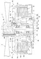
- FIG. 1 is a cross-sectional view showing the rotary propeller device of the first embodiment.
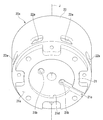
- FIG. 2 is a perspective view showing the stator holder of the first embodiment.
- FIG. 3 is a cross-sectional view showing the motor of the second embodiment.
- extending in the axial direction includes not only the case of extending in the axial direction but also the case of extending in a direction inclined by less than 45 ° with respect to the axial direction.
- “Extending in the radial direction” includes not only strictly extending in the radial direction, that is, in a direction perpendicular to the axial direction, but also extending in a direction inclined by less than 45 ° with respect to the radial direction. .
- the rotary propeller device 1 is, for example, a multicopter.
- the rotating propeller device 1 includes a motor 10 and a propeller 2.
- a propeller 2 is attached to the motor 10.
- the motor 10 includes a stationary shaft 33, a stator 30, a bearing 50, a rotor 40, an impeller 60, and a base member 20.
- the stationary shaft 33 is arranged around a central axis J extending in the vertical direction.
- the stationary shaft 33 is attached to the base member 20.
- the motor 10 is, for example, a fixed shaft type motor in which the stationary shaft 33 does not rotate.
- the stator 30 is opposed to a magnet 42b, which will be described later, in the radial direction through a gap.
- the stator 30 includes an annular stator core 31 and a plurality of coils 32.
- the bearing 50 is fixed to the stationary shaft 33.
- the bearing 50 rotatably supports the rotor 40 with respect to the stationary shaft 33.
- the bearing 50 includes, for example, an upper bearing 51 and a lower bearing 52 positioned below the upper bearing 51.
- the rotor 40 includes a bearing holding portion 43, a lid portion 41a, a magnet holding cylinder portion 41c, a magnet support member 42a, a magnet 42b, and a propeller mounting portion 44.
- the bearing holding portion 43 has a cylindrical shape that extends in the axial direction.
- the bearing holding portion 43 has a cylindrical shape centered on the central axis J.
- the bearing holding portion 43 is disposed on the outer side in the radial direction than the bearing 50.
- the bearing holding portion 43 is disposed on the radially inner side than the stator 30.
- the bearing holding part 43 holds the bearing 50 inside.
- the bearing holding portion 43 has a step portion 43a in which the outer diameter of the bearing holding portion 43 increases from the lower side toward the upper side.
- the lid portion 41a extends radially outward from the upper end portion of the bearing holding portion 43.
- the lid 41a is, for example, an annular shape, and the central axis J passes through the center of the lid 41a.
- the lid portion 41 a is disposed on the upper side of the stator 30.
- An end portion on the radially outer side of the lid portion 41 a is disposed on the radially outer side with respect to the stator 30.
- the magnet 42 b is disposed on the radially outer side of the stationary shaft 33, more specifically on the radially outer side of the stator 30.
- the propeller attachment portion 44 is a portion to which the propeller 2 is attached.
- the propeller attachment portion 44 has a columnar shape extending in the axial direction.
- the propeller mounting portion 44 is fixed to the upper end portion of the bearing holding portion 43 with, for example, screws.
- the rotor 40 has a rotor through hole 41 b that penetrates the rotor 40.
- the rotor through hole 41b is provided in the lid portion 41a.
- the rotor through hole 41b penetrates the lid portion 41a in the axial direction.
- the rotor through hole 41b is disposed above the impeller 60. At least a part of the rotor through-hole 41b is opposed to the stator 30 and the impeller 60 in the axial direction through a gap.
- the rotor 40 is provided with a plurality of rotor through holes 41b.
- the plurality of rotor through holes 41b may be arranged at equal intervals along the circumferential direction, or may not be at equal intervals.
- the shape of the rotor through-hole 41b is not particularly limited, and may be circular, elliptical, or polygonal.
- the impeller 60 is attached to the rotor 40. More specifically, the impeller 60 is fixed to the outer surface of the bearing holding portion 43. As shown in FIG. 1, in the shaft fixed type and outer rotor type motor 10, since the bearing holding portion 43 that holds the bearing 50 rotates, the impeller 60 can be fixed to the bearing holding portion 43. Therefore, the impeller 60 can be easily attached.
- the impeller 60 rotates together with the rotor 40 and causes the external air A to flow into the motor 10.
- the impeller 60 sends, for example, air A from above to below.
- the impeller 60 includes a blade support portion 61 and a plurality of impeller blades 62.
- the blade support 61 is, for example, a cylindrical shape centered on the central axis J.
- the blade support part 61 is fixed to the outer peripheral surface of the bearing holding part 43 with an adhesive or the like, for example.
- the blade support portion 61 may be fitted and fixed to the bearing holding portion 43.
- the upper end part of the blade support part 61 is in contact with the lower surface of the step part 43a, for example.
- the lower end portion of the blade support portion 61 is supported from below by a retaining ring fitted to the bearing holding portion 43, for example.
- the impeller 60 is positioned in the axial direction with respect to the bearing holding portion 43.
- the retaining ring fitted to the bearing holding portion 43 may have a protruding portion that protrudes upward and is inserted into a hole provided in the blade support portion 61. As a result, the protrusion is prevented from rotating, and the blade support 61 can be prevented from rotating relative to the bearing holder 43.
- the plurality of impeller blades 62 are arranged on the outer peripheral surface of the blade support portion 61.
- the plurality of impeller blades 62 are arranged along the circumferential direction. At least a part of the impeller 60 is disposed radially inward of the stator 30. At least a part of the impeller 60 and the stator 30 overlap in the radial direction. Therefore, the motor 10 can be reduced in size in the axial direction.
- the air A discharged downward from the impeller collides with the upper part of the stator. Therefore, the flow of the air A is easily disturbed, and the air A is not easily sent to the lower side of the stator. Thereby, there was a possibility that cooling of the stator might become insufficient. Moreover, since the flow of the air A is disturbed, there is a risk that noise will increase.
- the air A discharged downward from the impeller 60 can be prevented from colliding with the upper portion of the stator 30. . Thereby, it can suppress that the flow of the air A which flows in into the motor 10 is disturbed. As a result, the air A flowing into the motor 10 by the impeller 60 can be easily sent to the lower side of the stator 30 and the cooling of the stator 30 can be suppressed from being insufficient. Moreover, it can suppress that noise arises.
- the outer side in the radial direction of the impeller 60 is protected by the stator 30, for example, it is possible to suppress damage of the impeller 60 due to contact with other members or the like.
- the space inside the stator 30 in the radial direction can be used effectively.
- the space inside the stator 30 in the radial direction tends to be large when the number of poles of the stator 30 is relatively large. Therefore, the configuration of the present embodiment is particularly useful when the number of poles of the stator 30 is relatively large.
- the rotor 40 since the rotor 40 has the rotor through hole 41b above the impeller 60, the air A easily flows into the motor 10 from the external space above the impeller 60 through the rotor through hole 41b. Thereby, the flow of the air A can be easily generated in the motor 10, and the stator 30 can be cooled more easily.
- the rotor through-hole 41b is provided in the lid portion 41a, air A can be easily taken into the motor 10 from the upper side of the stator 30. Further, since at least a part of the rotor through-hole 41b faces the stator 30 and the impeller 60 in the axial direction through a gap, the upper portion of the stator 30 can be easily cooled by the air A, and the air A is introduced into the motor 10 by the impeller 60. It is easy to take in smoothly.
- the entire impeller 60 is disposed radially inward of the stator 30. Thereby, it can suppress more that the air A discharged
- the entire impeller 60 and the stator 30 overlap in the radial direction. Therefore, the motor 10 can be further downsized in the axial direction. Further, as shown in FIG. 1, the upper portion of the stator 30 can be cooled by the air A drawn to the upper side of the impeller 60, and the air A discharged downward from the impeller 60 can be easily sent to the lower side of the stator 30. Easy to cool the bottom. Thus, by easily cooling the stator 30 from both the upper side and the lower side, it is easy to efficiently cool the center in the axial direction of the stator 30 where the temperature tends to be high.
- the base member 20 has a stator holder 20a and a bracket 20b.
- the stator holder 20a extends in the axial direction. 1 and 2, the stator holder 20a has a bottomed cylindrical shape with the central axis J as the center.
- the stator holder 20a holds the stator 30.
- the stator holder 20 a has a bottom portion 21 and a stator holding cylinder portion 22. That is, the base member 20 has a bottom portion 21.
- the bottom 21 has a disk shape that expands in the radial direction. As shown in FIG. 1, the bottom 21 is disposed below the impeller 60.
- the bottom 21 covers the lower side of the impeller 60.
- the stator holding cylinder portion 22 has a cylindrical shape extending upward from the outer edge of the bottom portion 21.
- the inner peripheral surface of the stator core 31 is fixed to the outer peripheral surface of the stator holding cylinder portion 22. Thereby, the stator 30 is attached to the base member 20.
- the stator holder 20a has a first base member through hole 22a that penetrates the stator holder 20a in the radial direction.
- the first base member through hole 22 a is provided in the stator holding cylinder portion 22.
- the first base member through hole 22 a is disposed at the lower end portion of the stator holding cylinder portion 22.
- At least a part of the first base member through-hole 22 a is disposed below the impeller 60. Therefore, the air A sent by the impeller 60 is sent to the lower side of the stator 30 through the first base member through hole 22a. Thereby, the lower part of the stator 30 can be easily cooled, and the cooling efficiency of the stator 30 can be further improved.
- the entire first base member through-hole 22 a is disposed below the impeller 60.
- the first base member through hole 22a opens in a lower space of the stator 30, that is, a space between the stator 30 and the bracket 20b in the axial direction.
- the stator holder 20a has a plurality of first base member through holes 22a.
- the plurality of first base member through holes 22a are provided at equal intervals along the circumferential direction. Therefore, it is easy to cool the lower portion of the stator 30 uniformly over the entire circumferential direction.
- the shape of the first base member through-hole 22a is not particularly limited, and may be circular, elliptical, or polygonal.
- the shape of the first base member through hole 22 a is, for example, a rounded rectangular shape extending in the circumferential direction.
- the upper inner surface and the lower inner surface of the stator holder 20a that define the first base member through hole 22a are inclined surfaces that extend downward from the radially inner side toward the radially outer side. Therefore, it is easy to smoothly feed the air A discharged downward from the impeller 60 outward in the radial direction. This makes it easier to cool the lower portion of the stator 30.
- the inner surface of the stator holder 20a that defines the first base member through hole 22a is hereinafter referred to as the inner surface of the first base member through hole 22a.
- the lower inner surface of the first base member through-hole 22a is connected to the upper surface of the bottom portion 21. More specifically, it is connected to the inclined portion 21e on the upper surface of the bottom portion 21.
- the inclined portion 21e is disposed at the radially outer end of the upper surface of the bottom portion 21.
- the inclined portion 21e is provided in each of the plurality of first base member through holes 22a.
- the inclined portion 21e extends downward from the radially inner side toward the radially outer side. By the inclined portion 21e, the air A sent from the upper side of the bottom portion 21 can be smoothly sent to the first base member through hole 22a.
- the inclination of the inclined portion 21e with respect to the axial direction and the inclination of the lower surface of the first base member through hole 22a with respect to the axial direction are, for example, the same. Therefore, one continuous inclined surface is comprised by the inclined part 21e and the lower surface of the 1st base member through-hole 22a.
- the stator holder 20a has a plurality of second base member through holes 21b penetrating the stator holder 20a in the axial direction.
- the second base member through hole 21 b is provided in the bottom portion 21. That is, the bottom part 21 has the 2nd base member through-hole 21b which penetrates the bottom part 21 to an axial direction. Therefore, the water droplets W in the base member 20 (stator holder 20a) can be discharged to the outside through the second base member through hole 21b.
- the number of the second base member through-holes 21b is two, for example.
- the shape of the second base member through-hole 21b is not particularly limited, and may be circular, elliptical, or polygonal.
- the shape of the 2nd base member through-hole 21b is circular shape, for example. Further, the number of second base member through holes 21b may be one, or three or more.
- the groove 21c is connected to the second base member through hole 21b.
- the groove portion 21 c is recessed upward from the lower surface 21 a of the bottom portion 21.
- the groove 21c extends linearly in the radial direction.
- the groove portion 21c connects the second base member through-hole 21b and the outer edge on the radially outer side of the lower surface 21a. Therefore, as shown in FIG. 1, for example, when the rotary propeller device 1 is attached to the body BD of another member, even if the lower surface 21a is an attachment surface that contacts the body BD, Can be discharged to the outside of the rotary propeller device 1.
- FIG. 2 for example, only one groove portion 21c is provided, and is connected to one of the two second base member through holes 21b.
- the second base member through-hole 21b opens into a recess 21d provided in the lower surface 21a.
- the recess 21d is recessed upward from the lower surface 21a.
- the concave portion 21d has, for example, a circular shape, and the central axis J passes through the center thereof.
- a groove 21c is connected to the recess 21d. Therefore, the water droplet W passing through the second base member through hole 21b flows into the recess 21d and is discharged from the recess 21d to the outside of the rotary propeller device 1 through the groove 21c. Accordingly, when a plurality of second base member through holes 21b are provided, water droplets W passing through each second base member through hole 21b can be discharged to the outside of the rotary propeller device 1 even if there is one groove portion 21c.
- the opening area between the base member 20 and the body BD when the rotary propeller device 1 is fixed to the body BD can be reduced. Thereby, it can suppress that a foreign material enters into the inside of the rotation propeller apparatus 1 via the groove part 21c, for example. Further, since the water droplets W can be discharged from the plurality of second base member through holes 21b, the water droplets W in the base member 20 can be easily discharged.
- the bracket 20b is, for example, an annular plate member, and is disposed below the stator 30.
- the bracket 20b faces the stator 30 in the axial direction through a gap. Therefore, a flow path that extends in the radial direction and through which air A passes can be formed between the axial direction of the stator 30 and the bracket 20b.
- the air A that has flowed into the space below the stator 30 via the first base member through-hole 22a is sent in the radial direction and is easily brought into contact with the lower portion of the stator 30. Therefore, it is easier to cool the stator 30 with the air A.
- the upper surface of the bracket 20b is disposed below the lower inner surface of the first base member through hole 22a. Therefore, all of the air A discharged radially outward through the first base member through hole 22a can be easily sent to the space between the bracket 20b and the stator 30, and the stator 30 can be cooled more easily.
- the propeller 2 is, for example, a propeller for a multicopter.
- the propeller 2 is attached to the rotor 40. More specifically, the propeller 2 is attached to the propeller attachment portion 44.
- the propeller 2 includes an annular propeller fixing portion 2b and a plurality of propeller blades 2a.
- the propeller fixing portion 2b is fixed to the propeller mounting portion 44 with, for example, screws.
- the propeller blade 2a extends radially outward from the propeller fixing portion 2b.
- the present invention is not limited to the above-described embodiment, and other configurations can be adopted.
- the same configurations as those described above may be omitted by appropriately attaching the same reference numerals.
- a part of the impeller 60 may be disposed radially outside the inner edge of the stator 30.
- a part of the impeller 60 may be disposed at a position that does not overlap the stator 30 in the radial direction, that is, at a position different from the stator 30 in the axial direction.
- the rotor through hole 41b may be provided at a location other than the lid portion 41a in the rotor 40.
- the rotor through hole 41b may be provided in the magnet holding cylinder portion 41c.
- the rotor through hole 41b may penetrate the rotor 40 in the radial direction. Further, the entire rotor through hole 41b may face the stator 30 and / or the impeller 60 in the axial direction through a gap.
- the rotor through hole 41b may not be provided.
- the flow of the air A passing through the motor 10 by the impeller 60 may be opposite to the direction of the arrow shown in FIG. Specifically, for example, when the impeller 60 rotates, the air A flows from the gap between the bracket 20b and the rotor 40 through the axial gap between the stator 30 and the bracket 20b and the first base member through hole 22a. It flows into the motor 10. And the air A which flowed in in the motor 10 is discharged
- the flow direction of the air A in the motor 10 generated by the impeller 60 is the same as the flow direction of the air A generated in the motor 10 due to factors other than the impeller 60. This is because the flow of the air A flowing in the motor 10 can be made smoother and the cooling efficiency of the stator 30 can be further improved.
- the flow direction of the air A generated by the impeller 60 is changed to the air shown in FIG. 1.
- the direction of flow of A is preferably the same.
- the direction in which the air A flows in the motor 10 generated by the impeller 60 can be changed by changing the direction of the impeller blades 62.
- the first base member through hole 22a may not be provided.
- the second base member through hole 21b may not be provided.
- the bracket 20b may not be provided.
- the rotating shaft 133 is supported by the bearing 50 so as to be rotatable together with the rotor 140. That is, the motor 110 is a shaft rotation type motor. An upper end portion of the rotating shaft 133 is a propeller attachment portion 133a to which the propeller 2 is attached.
- the lid 141a is attached to the rotary shaft 133. More specifically, the lid 141a is fitted and fixed to the outer peripheral surface of the rotating shaft 133, for example.
- the impeller 160 is fixed to the lower surface of the lid 141a.
- wing support part 161 is fixed to the cover part 141a with a screw
- the impeller blade 162 is disposed on the lower surface of the blade support portion 161.
- the lower part of the impeller 160 and the stator 30 overlap in the radial direction.
- the upper part of the impeller 160 is disposed above the stator 30.
- the entire impeller 160 is disposed radially inward of the stator 30.
- the stator holder 120a has a bearing holding portion 143.
- the bearing holding portion 143 extends upward from the bottom portion 121.
- the inclined portion 121e of the bottom portion 121 extends in the radial direction from the bearing holding portion 143 to the first base member through hole 22a. Therefore, it is easy to send the air A discharged downward from the impeller 160 to the first base member through hole 22a more smoothly.
- the motor to which the present invention can be applied is not limited to an outer rotor type motor, but also includes an inner rotor type motor in which a rotor magnet is arranged radially inside the stator. Further, the motor to which the present invention is applied may be used in any device other than the rotating propeller device, such as a blower, an electric automobile, an electric airplane, and a robot.
- the configurations of the first embodiment and the second embodiment can be combined as appropriate within a range that does not contradict each other.
Landscapes
- Engineering & Computer Science (AREA)
- Power Engineering (AREA)
- Structures Of Non-Positive Displacement Pumps (AREA)
- Connection Of Motors, Electrical Generators, Mechanical Devices, And The Like (AREA)
Abstract
本発明の一つの態様のモータは、上下方向に延びる中心軸を中心として配置されるシャフトと、シャフトよりも径方向外側に配置されるマグネットを有するロータと、マグネットと隙間を介し径方向に対向するステータと、ロータに取り付けられるインペラと、を備える。インペラの少なくとも一部は、ステータよりも径方向内側に配置される。インペラの少なくとも一部とステータとは、径方向において重なる。本発明の一つの態様の回転プロペラ装置は、上記モータと、前記ロータに取り付けられるプロペラと、を備える。
Description
本発明は、モータ、および回転プロペラ装置に関する。
従来、回転子の回転に伴って外気を内部に吸入する羽根を有する直流モータが提案されている(例えば、特許文献1参照)。
しかし、上記のようなモータにおいては、羽根が固定子と軸方向に重なって設けられるため、モータが軸方向に大型化しやすい問題があった。
本発明の一つの態様は、上記問題点に鑑みて、インペラを有し、軸方向に大型化することを抑制できる構造を有するモータ、およびそのようなモータを備える回転プロペラ装置を提供することを目的の一つとする。
本発明の一つの態様のモータは、上下方向に延びる中心軸を中心として配置されるシャフトと、前記シャフトよりも径方向外側に配置されるマグネットを有するロータと、前記マグネットと隙間を介し径方向に対向するステータと、前記ロータに取り付けられるインペラと、を備え、前記インペラの少なくとも一部は、前記ステータの径方向内側に配置され、前記インペラの少なくとも一部と前記ステータとは、径方向において重なる。
本発明の一つの態様の回転プロペラ装置は、上記モータと、前記ロータに取り付けられるプロペラと、を備える。
本発明の一つの態様によれば、インペラを有し、軸方向に大型化することを抑制できる構造を有するモータ、およびそのようなモータを備える回転プロペラ装置が提供される。
以下、図面を参照しながら、本発明の実施形態に係るモータ、および回転プロペラ装置について説明する。以下の説明においては、図1の中心軸Jの延びる方向を上下方向とする。中心軸Jの軸方向の上側を単に「上側」と呼び、下側を単に「下側」と呼ぶ。
なお、上下方向は、単に説明のために用いられる名称であって、実際の位置関係や方向を限定しない。また、中心軸Jに平行な方向を単に「軸方向」と呼び、中心軸Jを中心とする径方向を単に「径方向」と呼び、中心軸Jを中心とする周方向を単に「周方向」と呼ぶ。
なお、上下方向は、単に説明のために用いられる名称であって、実際の位置関係や方向を限定しない。また、中心軸Jに平行な方向を単に「軸方向」と呼び、中心軸Jを中心とする径方向を単に「径方向」と呼び、中心軸Jを中心とする周方向を単に「周方向」と呼ぶ。
本明細書において、軸方向に延びる、とは、厳密に軸方向に延びる場合に加えて、軸方向に対して、45°未満の範囲で傾いた方向に延びる場合も含む。径方向に延びる、とは、厳密に径方向、すなわち、軸方向に対して垂直な方向に延びる場合に加えて、径方向に対して、45°未満の範囲で傾いた方向に延びる場合も含む。
図1に示す第1実施形態の回転プロペラ装置1は、例えば、マルチコプターである。回転プロペラ装置1は、モータ10と、プロペラ2と、を備える。モータ10には、プロペラ2が取り付けられる。モータ10は、静止シャフト33と、ステータ30と、ベアリング50と、ロータ40と、インペラ60と、ベース部材20と、を有する。
静止シャフト33は、上下方向に延びる中心軸Jを中心として配置される。静止シャフト33は、ベース部材20に取り付けられる。すなわち、モータ10は、例えば、静止シャフト33が回転しない軸固定型のモータである。ステータ30は、後述するマグネット42bと隙間を介し径方向に対向する。ステータ30は、環状のステータコア31と、複数のコイル32と、を有する。
ベアリング50は、静止シャフト33に固定される。ベアリング50は、ロータ40を静止シャフト33に対して回転可能に支持する。ベアリング50は、例えば、上ベアリング51と、上ベアリング51よりも下側に位置する下ベアリング52と、を有する。
ロータ40は、ベアリング保持部43と、蓋部41aと、マグネット保持筒部41cと、マグネット支持部材42aと、マグネット42bと、プロペラ取付部44と、を有する。ベアリング保持部43は、軸方向に延びる筒状である。ベアリング保持部43は、例えば、中心軸Jを中心とする円筒状である。ベアリング保持部43は、ベアリング50よりも径方向外側に配置される。ベアリング保持部43は、ステータ30よりも径方向内側に配置される。ベアリング保持部43は、内部にベアリング50を保持する。ベアリング保持部43は、下側から上側に向かってベアリング保持部43の外径が大きくなる段差部43aを有する。
蓋部41aは、ベアリング保持部43の上端部から径方向外側に拡がる。蓋部41aは、例えば、円環状であり、蓋部41aの中心を中心軸Jが通る。蓋部41aは、ステータ30の上側に配置される。蓋部41aの径方向外側の端部は、ステータ30よりも径方向外側に配置される。マグネット42bは、静止シャフト33よりも径方向外側、より詳細にはステータ30の径方向外側に配置される。
プロペラ取付部44は、プロペラ2が取り付けられる部分である。プロペラ取付部44は、軸方向に延びる柱状である。プロペラ取付部44は、例えば、ネジ等によってベアリング保持部43の上端部に固定される。
ロータ40は、ロータ40を貫通するロータ貫通孔41bを有する。ロータ貫通孔41bは、蓋部41aに設けられる。ロータ貫通孔41bは、例えば、蓋部41aを軸方向に貫通する。ロータ貫通孔41bは、インペラ60よりも上側に配置される。ロータ貫通孔41bの少なくとも一部は、ステータ30およびインペラ60と隙間を介し軸方向に対向する。
ロータ40には、複数のロータ貫通孔41bが配置される。複数のロータ貫通孔41bは、周方向に沿って等間隔に配置されてもよいし、等間隔でなくてもよい。ロータ貫通孔41bの形状は、特に限定されず、円形状であってもよいし、楕円形状であってもよいし、多角形状であってもよい。
インペラ60は、ロータ40に取り付けられる。より詳細には、インペラ60は、ベアリング保持部43の外側面に固定される。図1に示すように、軸固定型で、かつ、アウターロータ型のモータ10では、ベアリング50を保持するベアリング保持部43が回転するため、ベアリング保持部43にインペラ60を固定できる。したがって、インペラ60の取り付けが容易である。
インペラ60は、ロータ40と共に回転し、モータ10の内部に外部の空気Aを流入させる。図1では、インペラ60は、例えば、空気Aを上方から下方へと送る。インペラ60は、羽根支持部61と、複数のインペラ羽根62と、を有する。羽根支持部61は、例えば、中心軸Jを中心とする円筒状である。羽根支持部61は、例えば、ベアリング保持部43の外周面に接着剤等によって固定される。なお、羽根支持部61は、ベアリング保持部43に嵌め合わされて固定されてもよい。
羽根支持部61の上端部は、例えば、段差部43aの下面に接触する。図示は省略するが、羽根支持部61の下端部は、例えば、ベアリング保持部43に嵌められた止め輪によって下側から支持される。これにより、インペラ60は、ベアリング保持部43に対して、軸方向に位置決めされる。このとき、ベアリング保持部43に嵌められた止め輪は、上側に突出し羽根支持部61に設けられた穴に挿入される突出部を有してもよい。これにより、突出部が回り止めとなって、羽根支持部61がベアリング保持部43に対して相対的に回転することを抑制できる。
複数のインペラ羽根62は、羽根支持部61の外周面に配置される。複数のインペラ羽根62は、周方向に沿って配置される。インペラ60の少なくとも一部は、ステータ30よりも径方向内側に配置される。インペラ60の少なくとも一部とステータ30とは、径方向において重なる。そのため、モータ10を軸方向に小型化できる。
また、例えば、ステータの直上にインペラが設けられる場合、インペラから下向きに排出される空気Aがステータの上部と衝突する。そのため、空気Aの流れが乱れやすく、空気Aがステータの下側に送られにくい。これにより、ステータの冷却が不十分になる虞があった。また、空気Aの流れが乱れるため、騒音が大きくなる虞もあった。
これに対して、本実施形態によれば、インペラ60の少なくとも一部がステータ30と径方向に重なるため、インペラ60から下向きに排出される空気Aがステータ30の上部に衝突することを抑制できる。これにより、モータ10内部に流入される空気Aの流れが乱れることを抑制できる。その結果、インペラ60によってモータ10内に流入される空気Aをステータ30の下側に送りやすく、ステータ30の冷却が不十分になることを抑制できる。また、騒音が生じることを抑制できる。
また、インペラ60の径方向外側がステータ30によって保護されるため、例えば、他の部材等が接触してインペラ60が破損することを抑制できる。
また、インペラ60の少なくとも一部がステータ30の径方向内側の空間に配置されることで、ステータ30の径方向内側の空間を有効に活用できる。ステータ30の径方向内側の空間は、ステータ30の極数が比較的多い場合に大きくなりやすい。そのため、ステータ30の極数が比較的大きい場合に、本実施形態の構成は特に有用である。
また、ロータ40はインペラ60よりも上側にロータ貫通孔41bを有するため、インペラ60よりも上側の外部空間から、ロータ貫通孔41bを介してモータ10内に空気Aが流入しやすい。これにより、モータ10内に空気Aの流れを生じやすくでき、ステータ30をより冷却しやすい。
また、ロータ貫通孔41bは、蓋部41aに設けられるため、ステータ30の上側から空気Aをモータ10内に取り入れやすい。また、ロータ貫通孔41bの少なくとも一部は、ステータ30およびインペラ60と隙間を介し軸方向に対向するため、空気Aによってステータ30の上部を冷却しやすいと共に、インペラ60によってモータ10内に空気Aを滑らかに取り入れやすい。
図1では、インペラ60の全体は、ステータ30よりも径方向内側に配置される。これにより、インペラ60から下向きに排出される空気Aがステータ30の上部に衝突することをより抑制できる。そのため、モータ10内部の空気Aの流れをより滑らかにできると共に、騒音が生じることをより抑制できる。
図1では、インペラ60の全体とステータ30とは、径方向において重なる。そのため、モータ10をより軸方向に小型化できる。また、図1に示すように、インペラ60の上側に引き込まれる空気Aによってステータ30の上部を冷却できると共に、インペラ60から下向きに排出される空気Aをステータ30の下側に送りやすくステータ30の下部を冷却しやすい。このように、ステータ30を上側と下側との両方から冷却しやすいことで、温度が高温となりやすいステータ30の軸方向の中心を効率的に冷却しやすい。
ベース部材20は、ステータホルダ20aと、ブラケット20bと、を有する。ステータホルダ20aは、軸方向に延びる。図1および図2では、ステータホルダ20aは、中心軸Jを中心とする有底の円筒状である。ステータホルダ20aは、ステータ30を保持する。ステータホルダ20aは、底部21と、ステータ保持筒部22と、を有する。すなわち、ベース部材20は、底部21を有する。底部21は、径方向に拡がる円板状である。図1に示すように、底部21は、インペラ60の下側に配置される。底部21は、インペラ60の下側を覆う。
ステータ保持筒部22は、底部21の外縁から上側に延びる円筒状である。ステータ保持筒部22の外周面には、ステータコア31の内周面が固定される。これにより、ステータ30は、ベース部材20に取り付けられる。
ステータホルダ20aは、ステータホルダ20aを径方向に貫通する第1ベース部材貫通孔22aを有する。第1ベース部材貫通孔22aは、ステータ保持筒部22に設けられる。第1ベース部材貫通孔22aは、ステータ保持筒部22の下端部に配置される。第1ベース部材貫通孔22aは、少なくとも一部がインペラ60よりも下側に配置される。そのため、インペラ60によって送られる空気Aが第1ベース部材貫通孔22aを介して、ステータ30の下側に送られる。これにより、ステータ30の下部を冷却しやすく、ステータ30の冷却効率をより向上できる。
図1では、第1ベース部材貫通孔22aの全体は、インペラ60よりも下側に配置される。第1ベース部材貫通孔22aは、ステータ30の下側の空間、すなわちステータ30とブラケット20bとの軸方向の間の空間に開口する。
図2に示すように、ステータホルダ20aは、複数の第1ベース部材貫通孔22aを有する。複数の第1ベース部材貫通孔22aは、周方向に沿って等間隔に設けられる。そのため、ステータ30の下部を周方向の全体に亘って均等に冷却しやすい。
第1ベース部材貫通孔22aの形状は、特に限定されず、円形状であっても、楕円形状であっても、多角形状であってもよい。図2では、第1ベース部材貫通孔22aの形状は、例えば、周方向に延びる角丸の長方形状である。
図1に示すように、第1ベース部材貫通孔22aを規定するステータホルダ20aの上内側面および下内側面は、径方向内側から径方向外側に向かうに従って下側に延びる傾斜面である。そのため、インペラ60から下向きに排出される空気Aを、径方向外側に滑らかに送りやすい。これにより、ステータ30の下部をより冷却しやすい。第1ベース部材貫通孔22aを規定するステータホルダ20aの内側面は、以下、第1ベース部材貫通孔22aの内側面と記す。
第1ベース部材貫通孔22aの下内側面は、底部21の上面と接続される。より詳細には、底部21の上面のうちの傾斜部21eと接続される。傾斜部21eは、底部21の上面の径方向外側の端部に配置される。傾斜部21eは、複数の第1ベース部材貫通孔22aのそれぞれに設けられる。傾斜部21eは、径方向内側から径方向外側に向かうに従って下側に延びる。傾斜部21eによって、底部21の上側から送られてくる空気Aを第1ベース部材貫通孔22aに滑らかに送ることができる。
傾斜部21eの軸方向に対する傾きと第1ベース部材貫通孔22aの下面の軸方向に対する傾きとは、例えば、互いに同じである。そのため、傾斜部21eと第1ベース部材貫通孔22aの下面とによって、1つの連続した傾斜面が構成される。
ステータホルダ20aは、ステータホルダ20aを軸方向に貫通する複数の第2ベース部材貫通孔21bを有する。第2ベース部材貫通孔21bは、底部21に設けられる。すなわち、底部21は、底部21を軸方向に貫通する第2ベース部材貫通孔21bを有する。そのため、第2ベース部材貫通孔21bを介して、ベース部材20(ステータホルダ20a)内の水滴Wを外部に排出することができる。
図2では、第2ベース部材貫通孔21bの数は、例えば、2つである。第2ベース部材貫通孔21bの形状は、特に限定されず、円形状であっても、楕円形状であっても、多角形状であってもよい。図2では、第2ベース部材貫通孔21bの形状は、例えば、円形状である。また、第2ベース部材貫通孔21bの数は、1つ、または3つ以上であってもよい。
第2ベース部材貫通孔21bには、溝部21cが接続される。溝部21cは、底部21の下面21aから上側に窪む。溝部21cは、例えば、径方向に直線状に延びる。溝部21cは、第2ベース部材貫通孔21bと下面21aの径方向外側の外縁とを繋ぐ。そのため、図1に示すように、例えば、回転プロペラ装置1が他の部材のボディBDに取り付けられる際、下面21aがボディBDと接触する取付面であっても、溝部21cを介して、水滴Wを回転プロペラ装置1の外部に排出できる。図2では、溝部21cは、例えば、1つのみ設けられ、2つの第2ベース部材貫通孔21bのうちの一方と接続される。
第2ベース部材貫通孔21bは、下面21aに設けられた凹部21dに開口する。凹部21dは、下面21aから上側に窪む。凹部21dは、例えば、円形状であり、その中心を中心軸Jが通る。凹部21dには、溝部21cが接続される。そのため、第2ベース部材貫通孔21bを通る水滴Wは、凹部21dに流入し、凹部21dから溝部21cを介して、回転プロペラ装置1の外部に排出される。これにより、第2ベース部材貫通孔21bが複数設けられる場合に、溝部21cが1つであっても、各第2ベース部材貫通孔21bを通る水滴Wを回転プロペラ装置1の外部に排出できる。
溝部21cを1つとすることで、回転プロペラ装置1をボディBDに固定した際におけるベース部材20とボディBDとの間の開口面積を小さくできる。これにより、例えば、溝部21cを介して回転プロペラ装置1の内部に異物が入り込むことを抑制できる。また、複数の第2ベース部材貫通孔21bから水滴Wを排出できるため、ベース部材20内の水滴Wを排出しやすくできる。
回転プロペラ装置1を屋外で使用する場合、モータ10内に水滴Wが浸入しやすい。そのため、上述したベース部材20内の水滴Wを排出できる効果は、例えば、マルチコプター等のように、回転プロペラ装置1を屋外で使用する場合に、特に大きく得られる。
ブラケット20bは、例えば、円環板状の部材であり、ステータ30よりも下側に配置される。ブラケット20bは、ステータ30と隙間を介し軸方向に対向する。そのため、ステータ30とブラケット20bとの軸方向の間に、径方向に延び空気Aが通る流路を構成することができる。これにより、第1ベース部材貫通孔22aを介して、ステータ30の下側の空間に流入した空気Aを、径方向に送って、ステータ30の下部に接触させやすい。したがって、ステータ30を空気Aによって、より冷却しやすい。
ブラケット20bの上面は、第1ベース部材貫通孔22aの下内側面よりも下側に配置される。そのため、第1ベース部材貫通孔22aを介して径方向外側に排出される空気Aのすべてをブラケット20bとステータ30との間の空間に送りやすく、ステータ30をより冷却しやすい。
プロペラ2は、例えば、マルチコプター用のプロペラである。プロペラ2は、ロータ40に取り付けられる。より詳細には、プロペラ2は、プロペラ取付部44に取り付けられる。プロペラ2は、環状のプロペラ固定部2bと、複数のプロペラ羽根2aと、を有する。プロペラ固定部2bは、例えばネジ等によってプロペラ取付部44に固定される。プロペラ羽根2aは、プロペラ固定部2bから径方向外側に延びる。
本発明は上述の実施形態に限られず、他の構成を採用することもできる。以下の説明において上記説明と同様の構成については、適宜同一の符号を付す等により説明を省略する場合がある。
インペラ60の一部は、ステータ30の内縁よりも径方向外側に配置されてもよい。インペラ60の一部は、ステータ30と径方向において重ならない位置、すなわち、軸方向においてステータ30と異なる位置に配置されてもよい。
ロータ貫通孔41bは、ロータ40における蓋部41a以外の箇所に設けられてもよい。例えば、ロータ貫通孔41bは、マグネット保持筒部41cに設けられてもよい。ロータ貫通孔41bは、ロータ40を径方向に貫通してもよい。また、ロータ貫通孔41bの全体が、ステータ30および/またはインペラ60と隙間を介し軸方向に対向してもよい。ロータ貫通孔41bは、設けられなくてもよい。
インペラ60によってモータ10内を通る空気Aの流れは、図1に示す矢印の向きと逆向きであってもよい。具体的には、例えば、インペラ60が回転することで、ブラケット20bとロータ40との隙間からステータ30とブラケット20bとの軸方向の隙間および第1ベース部材貫通孔22aを介して、空気Aがモータ10内に流入される。そして、モータ10内に流入された空気Aは、インペラ60から上向きに排出され、ロータ貫通孔41bを介して、モータ10の外部に排出される。
インペラ60によって生じるモータ10内の空気Aの流れる向きは、インペラ60以外の要因でモータ10内に生じる空気Aの流れる向きと同じ向きとすることが好ましい。モータ10内において流れる空気Aの流れをより滑らかにでき、ステータ30の冷却効率をより向上できるためである。
具体的には、例えば、プロペラ2が回転することで、モータ10内に上方から下方に流れる空気Aの流れが生じる場合には、インペラ60によって生じる空気Aの流れる向きを、図1に示す空気Aの流れの向きと同じにすることが好ましい。インペラ60によって生じるモータ10内の空気Aの流れる向きは、インペラ羽根62の向きを変更することで、変更できる。
第1ベース部材貫通孔22aは、設けられなくてもよい。第2ベース部材貫通孔21bは、設けられなくてもよい。ブラケット20bは、設けられてなくてもよい。
図3に示すように、第2実施形態のモータ110では、回転シャフト133は、ベアリング50によって、ロータ140と共に回転可能に支持される。すなわち、モータ110は、軸回転型のモータである。回転シャフト133の上端部は、プロペラ2が取り付けられるプロペラ取付部133aである。
蓋部141aは、回転シャフト133に取り付けられる。より詳細には、蓋部141aは、例えば、回転シャフト133の外周面に嵌め合わされて固定される。
インペラ160は、蓋部141aの下面に固定される。より詳細には、羽根支持部161は、例えば、ネジ等によって蓋部141aに固定される。インペラ羽根162は、羽根支持部161の下面に配置される。インペラ160の下部とステータ30とは、径方向において重なる。インペラ160の上部は、ステータ30よりも上側に配置される。インペラ160の全体は、ステータ30よりも径方向内側に配置される。
ベース部材120において、ステータホルダ120aは、ベアリング保持部143を有する。ベアリング保持部143は、底部121から上側に延びる。底部121の傾斜部121eは、ベアリング保持部143から第1ベース部材貫通孔22aまで径方向に延びる。そのため、インペラ160から下向きに排出される空気Aを、より滑らかに第1ベース部材貫通孔22aに送りやすい。
本発明が適用できるモータは、アウターロータ型のモータに限られず、ステータの径方向内側にロータのマグネットが配置されるインナーロータ型のモータも含む。また、本発明が適用されたモータは、例えば、送風装置、電動自動車、電動飛行機およびロボット等、回転プロペラ装置以外のいかなる機器に用いられてもよい。
上記第1実施形態および第2実施形態の各構成は、相互に矛盾しない範囲内において、適宜組み合わせることができる。
1…回転プロペラ装置、2…プロペラ、10,110…モータ、20,120…ベース部材、20a,120a…ステータホルダ、20b…ブラケット、21,121…底部、21a…下面、21b…第2ベース部材貫通孔、22a…第1ベース部材貫通孔、30…ステータ、33…静止シャフト(シャフト)、40,140…ロータ、41a,141a…蓋部、41b…ロータ貫通孔、42b…マグネット、43…ベアリング保持部、50…ベアリング、60,160…インペラ、133…回転シャフト(シャフト)、J…中心軸
Claims (12)
- 上下方向に延びる中心軸を中心として配置されるシャフトと、
前記シャフトよりも径方向外側に配置されるマグネットを有するロータと、
前記マグネットと隙間を介し径方向に対向するステータと、
前記ロータに取り付けられるインペラと、
を備え、
前記インペラの少なくとも一部は、前記ステータよりも径方向内側に配置され、
前記インペラの少なくとも一部と前記ステータとは、径方向において重なる、モータ。 - 前記インペラの全体は、前記ステータよりも径方向内側に配置される、請求項1に記載のモータ。
- 前記インペラの全体と前記ステータとは、径方向において重なる、請求項2に記載のモータ。
- 前記マグネットは、前記ステータの径方向外側に配置され、
前記ロータは、前記ロータを貫通するロータ貫通孔を有し、
前記ロータ貫通孔は、インペラよりも上側に配置される、請求項1から3のいずれか一項に記載のモータ。 - 前記ロータは、前記ステータの上側に配置される蓋部を有し、
前記ロータ貫通孔は、前記蓋部に設けられる、請求項4に記載のモータ。 - 前記ロータ貫通孔の少なくとも一部は、前記ステータおよび前記インペラと隙間を介し軸方向に対向する、請求項5に記載のモータ。
- 前記ステータが取り付けられるベース部材をさらに備え、
前記ベース部材は、軸方向に延び前記ステータを保持するステータホルダを有し、
前記ステータホルダは、前記ステータホルダを径方向に貫通する第1ベース部材貫通孔を有し、
前記第1ベース部材貫通孔の少なくとも一部が、前記インペラよりも下側に配置される、請求項1から6のいずれか一項に記載のモータ。 - 前記ベース部材は、前記ステータと隙間を介し軸方向に対向するブラケットを有し、
前記ブラケットは、前記ステータよりも下側に配置される、請求項7に記載のモータ。 - 前記ステータおよび前記シャフトが取り付けられるベース部材と、
前記ロータを前記シャフトに対して回転可能に支持するベアリングと、
をさらに備え、
前記ロータは、前記ベアリングを保持する筒状のベアリング保持部を有し、
前記ベアリング保持部は、前記ベアリングよりも径方向外側に配置され、
前記インペラは、前記ベアリング保持部の外側面に固定される、請求項1から8のいずれか一項に記載のモータ。 - 前記シャフトは、前記ロータと共に回転可能に支持され、
前記ロータは、前記シャフトに取り付けられる蓋部を有し、
前記蓋部は、前記ステータの上側に配置され、
前記インペラは、前記蓋部の下面に固定される、請求項1から8のいずれか一項に記載のモータ。 - 前記ステータが取り付けられるベース部材をさらに備え、
前記ベース部材は、前記インペラの下側に配置される底部を有し、
前記底部は、前記底部を軸方向に貫通する第2ベース部材貫通孔を有する、請求項1から10のいずれか一項に記載のモータ。 - 請求項1から11のいずれか一項に記載のモータと、
前記ロータに取り付けられるプロペラと、
を備える、回転プロペラ装置。
Priority Applications (1)
| Application Number | Priority Date | Filing Date | Title |
|---|---|---|---|
| CN201690001183.1U CN208522602U (zh) | 2015-09-25 | 2016-09-16 | 马达和旋转螺旋桨装置 |
Applications Claiming Priority (2)
| Application Number | Priority Date | Filing Date | Title |
|---|---|---|---|
| JP2015187823 | 2015-09-25 | ||
| JP2015-187823 | 2015-09-25 |
Publications (1)
| Publication Number | Publication Date |
|---|---|
| WO2017051784A1 true WO2017051784A1 (ja) | 2017-03-30 |
Family
ID=58386684
Family Applications (1)
| Application Number | Title | Priority Date | Filing Date |
|---|---|---|---|
| PCT/JP2016/077573 Ceased WO2017051784A1 (ja) | 2015-09-25 | 2016-09-16 | モータ、および回転プロペラ装置 |
Country Status (2)
| Country | Link |
|---|---|
| CN (1) | CN208522602U (ja) |
| WO (1) | WO2017051784A1 (ja) |
Cited By (6)
| Publication number | Priority date | Publication date | Assignee | Title |
|---|---|---|---|---|
| CN107154706A (zh) * | 2017-05-24 | 2017-09-12 | 河南师范大学 | 一种电机散热结构 |
| WO2018216599A1 (ja) * | 2017-05-23 | 2018-11-29 | 澤藤電機株式会社 | アウターロータ型電動機におけるロータ構造 |
| JP2020099148A (ja) * | 2018-12-19 | 2020-06-25 | Thk株式会社 | アクチュエータ |
| JP2021170861A (ja) * | 2020-04-14 | 2021-10-28 | 株式会社エクセディ | モータ |
| JP2023035186A (ja) * | 2021-08-31 | 2023-03-13 | 日本電産株式会社 | モータ及び航空機 |
| WO2023079844A1 (ja) * | 2021-11-05 | 2023-05-11 | パナソニックIpマネジメント株式会社 | モータ、ブロア、及び、車両 |
Citations (7)
| Publication number | Priority date | Publication date | Assignee | Title |
|---|---|---|---|---|
| JPS59159168U (ja) * | 1983-04-07 | 1984-10-25 | 本田技研工業株式会社 | 発電機の冷却装置 |
| JPH01159568U (ja) * | 1988-04-21 | 1989-11-06 | ||
| JP2000324757A (ja) * | 1999-05-07 | 2000-11-24 | Toshiba Corp | アウターロータ形モータ |
| JP2002354751A (ja) * | 2001-05-18 | 2002-12-06 | Fujitsu General Ltd | 電動機 |
| JP2003047197A (ja) * | 2001-07-31 | 2003-02-14 | Nidec Shibaura Corp | 電動機 |
| JP2009171751A (ja) * | 2008-01-17 | 2009-07-30 | Calsonic Kansei Corp | ファンモータ |
| JP2015095997A (ja) * | 2013-11-13 | 2015-05-18 | 日本電産株式会社 | モータ |
-
2016
- 2016-09-16 CN CN201690001183.1U patent/CN208522602U/zh not_active Expired - Fee Related
- 2016-09-16 WO PCT/JP2016/077573 patent/WO2017051784A1/ja not_active Ceased
Patent Citations (7)
| Publication number | Priority date | Publication date | Assignee | Title |
|---|---|---|---|---|
| JPS59159168U (ja) * | 1983-04-07 | 1984-10-25 | 本田技研工業株式会社 | 発電機の冷却装置 |
| JPH01159568U (ja) * | 1988-04-21 | 1989-11-06 | ||
| JP2000324757A (ja) * | 1999-05-07 | 2000-11-24 | Toshiba Corp | アウターロータ形モータ |
| JP2002354751A (ja) * | 2001-05-18 | 2002-12-06 | Fujitsu General Ltd | 電動機 |
| JP2003047197A (ja) * | 2001-07-31 | 2003-02-14 | Nidec Shibaura Corp | 電動機 |
| JP2009171751A (ja) * | 2008-01-17 | 2009-07-30 | Calsonic Kansei Corp | ファンモータ |
| JP2015095997A (ja) * | 2013-11-13 | 2015-05-18 | 日本電産株式会社 | モータ |
Cited By (12)
| Publication number | Priority date | Publication date | Assignee | Title |
|---|---|---|---|---|
| WO2018216599A1 (ja) * | 2017-05-23 | 2018-11-29 | 澤藤電機株式会社 | アウターロータ型電動機におけるロータ構造 |
| JP2020145766A (ja) * | 2017-05-23 | 2020-09-10 | 澤藤電機株式会社 | アウターロータ型電動機におけるロータ構造 |
| US11088595B2 (en) | 2017-05-23 | 2021-08-10 | Sawafuji Electric Co., Ltd. | Rotor structure for outer rotor electric motor |
| CN107154706A (zh) * | 2017-05-24 | 2017-09-12 | 河南师范大学 | 一种电机散热结构 |
| JP2020099148A (ja) * | 2018-12-19 | 2020-06-25 | Thk株式会社 | アクチュエータ |
| WO2020129678A1 (ja) * | 2018-12-19 | 2020-06-25 | Thk株式会社 | アクチュエータ |
| JP7465624B2 (ja) | 2018-12-19 | 2024-04-11 | Thk株式会社 | アクチュエータ |
| JP2021170861A (ja) * | 2020-04-14 | 2021-10-28 | 株式会社エクセディ | モータ |
| JP7490434B2 (ja) | 2020-04-14 | 2024-05-27 | 株式会社エクセディ | モータ |
| JP2023035186A (ja) * | 2021-08-31 | 2023-03-13 | 日本電産株式会社 | モータ及び航空機 |
| JP7727449B2 (ja) | 2021-08-31 | 2025-08-21 | ニデック株式会社 | モータ及び航空機 |
| WO2023079844A1 (ja) * | 2021-11-05 | 2023-05-11 | パナソニックIpマネジメント株式会社 | モータ、ブロア、及び、車両 |
Also Published As
| Publication number | Publication date |
|---|---|
| CN208522602U (zh) | 2019-02-19 |
Similar Documents
| Publication | Publication Date | Title |
|---|---|---|
| WO2017051784A1 (ja) | モータ、および回転プロペラ装置 | |
| US11078926B2 (en) | Blower | |
| US7946804B2 (en) | Axial fan unit having reduced noise generation | |
| US8899946B2 (en) | Fan having a balance correction portion | |
| US12009724B2 (en) | Motor and rotor blade apparatus | |
| US10184492B2 (en) | Axial flow fan | |
| US11682933B2 (en) | Motor and fan motor | |
| KR102104565B1 (ko) | 드론용 모터의 방열 구조 | |
| JP2011052684A (ja) | 送風ファン | |
| US11215185B2 (en) | Axial fan | |
| JP2013122193A (ja) | ファン | |
| CN111379715A (zh) | 送风装置 | |
| US10224777B2 (en) | Brushless motor with water stopping walls creating labyrinth structure | |
| JP2020167806A (ja) | モータ、回転翼装置、および無人飛行体 | |
| KR20160078184A (ko) | 회전자 | |
| JP2012163021A (ja) | 送風ファン | |
| US20070264123A1 (en) | Counter-rotating fan | |
| JP2019178656A (ja) | 二重反転式ファン | |
| US20230066950A1 (en) | Motor and aircraft | |
| JP2025175103A (ja) | モータ | |
| JP2010216280A (ja) | 遠心ファン | |
| US11339795B2 (en) | Air blower | |
| JP2012127361A (ja) | ファン装置 | |
| JP2018519471A (ja) | ファン及びファンを備える換気ユニット | |
| JP5892122B2 (ja) | ファン装置及び電子機器 |
Legal Events
| Date | Code | Title | Description |
|---|---|---|---|
| 121 | Ep: the epo has been informed by wipo that ep was designated in this application |
Ref document number: 16848572 Country of ref document: EP Kind code of ref document: A1 |
|
| NENP | Non-entry into the national phase |
Ref country code: DE |
|
| 122 | Ep: pct application non-entry in european phase |
Ref document number: 16848572 Country of ref document: EP Kind code of ref document: A1 |
|
| NENP | Non-entry into the national phase |
Ref country code: JP |