WO2017051697A1 - 車載用電源装置 - Google Patents
車載用電源装置 Download PDFInfo
- Publication number
- WO2017051697A1 WO2017051697A1 PCT/JP2016/076063 JP2016076063W WO2017051697A1 WO 2017051697 A1 WO2017051697 A1 WO 2017051697A1 JP 2016076063 W JP2016076063 W JP 2016076063W WO 2017051697 A1 WO2017051697 A1 WO 2017051697A1
- Authority
- WO
- WIPO (PCT)
- Prior art keywords
- load
- storage device
- power storage
- wiring
- resistance value
- Prior art date
- Legal status (The legal status is an assumption and is not a legal conclusion. Google has not performed a legal analysis and makes no representation as to the accuracy of the status listed.)
- Ceased
Links
Images

Classifications
-
- B—PERFORMING OPERATIONS; TRANSPORTING
- B60—VEHICLES IN GENERAL
- B60R—VEHICLES, VEHICLE FITTINGS, OR VEHICLE PARTS, NOT OTHERWISE PROVIDED FOR
- B60R16/00—Electric or fluid circuits specially adapted for vehicles and not otherwise provided for; Arrangement of elements of electric or fluid circuits specially adapted for vehicles and not otherwise provided for
- B60R16/02—Electric or fluid circuits specially adapted for vehicles and not otherwise provided for; Arrangement of elements of electric or fluid circuits specially adapted for vehicles and not otherwise provided for electric constitutive elements
- B60R16/03—Electric or fluid circuits specially adapted for vehicles and not otherwise provided for; Arrangement of elements of electric or fluid circuits specially adapted for vehicles and not otherwise provided for electric constitutive elements for supply of electrical power to vehicle subsystems or for
- B60R16/033—Electric or fluid circuits specially adapted for vehicles and not otherwise provided for; Arrangement of elements of electric or fluid circuits specially adapted for vehicles and not otherwise provided for electric constitutive elements for supply of electrical power to vehicle subsystems or for characterised by the use of electrical cells or batteries
-
- B—PERFORMING OPERATIONS; TRANSPORTING
- B60—VEHICLES IN GENERAL
- B60R—VEHICLES, VEHICLE FITTINGS, OR VEHICLE PARTS, NOT OTHERWISE PROVIDED FOR
- B60R16/00—Electric or fluid circuits specially adapted for vehicles and not otherwise provided for; Arrangement of elements of electric or fluid circuits specially adapted for vehicles and not otherwise provided for
- B60R16/02—Electric or fluid circuits specially adapted for vehicles and not otherwise provided for; Arrangement of elements of electric or fluid circuits specially adapted for vehicles and not otherwise provided for electric constitutive elements
- B60R16/0207—Wire harnesses
-
- H—ELECTRICITY
- H01—ELECTRIC ELEMENTS
- H01M—PROCESSES OR MEANS, e.g. BATTERIES, FOR THE DIRECT CONVERSION OF CHEMICAL ENERGY INTO ELECTRICAL ENERGY
- H01M10/00—Secondary cells; Manufacture thereof
- H01M10/42—Methods or arrangements for servicing or maintenance of secondary cells or secondary half-cells
- H01M10/44—Methods for charging or discharging
- H01M10/441—Methods for charging or discharging for several batteries or cells simultaneously or sequentially
-
- H—ELECTRICITY
- H02—GENERATION; CONVERSION OR DISTRIBUTION OF ELECTRIC POWER
- H02J—ELECTRIC POWER NETWORKS; CIRCUIT ARRANGEMENTS OR SYSTEMS FOR SUPPLYING OR DISTRIBUTING ELECTRIC POWER; SYSTEMS FOR STORING ELECTRIC ENERGY
- H02J7/00—Circuit arrangements for charging or discharging batteries or for supplying loads from batteries
- H02J7/34—Parallel operation in networks using both storage and other DC sources, e.g. providing buffering
-
- H—ELECTRICITY
- H02—GENERATION; CONVERSION OR DISTRIBUTION OF ELECTRIC POWER
- H02J—ELECTRIC POWER NETWORKS; CIRCUIT ARRANGEMENTS OR SYSTEMS FOR SUPPLYING OR DISTRIBUTING ELECTRIC POWER; SYSTEMS FOR STORING ELECTRIC ENERGY
- H02J7/00—Circuit arrangements for charging or discharging batteries or for supplying loads from batteries
- H02J7/855—Circuit arrangements for charging or discharging batteries or for supplying loads from batteries with circuits adapted for supplying loads from the battery
-
- H—ELECTRICITY
- H02—GENERATION; CONVERSION OR DISTRIBUTION OF ELECTRIC POWER
- H02J—ELECTRIC POWER NETWORKS; CIRCUIT ARRANGEMENTS OR SYSTEMS FOR SUPPLYING OR DISTRIBUTING ELECTRIC POWER; SYSTEMS FOR STORING ELECTRIC ENERGY
- H02J7/00—Circuit arrangements for charging or discharging batteries or for supplying loads from batteries
- H02J7/90—Regulation of charging or discharging current or voltage
- H02J7/94—Regulation of charging or discharging current or voltage in response to battery current
-
- H—ELECTRICITY
- H01—ELECTRIC ELEMENTS
- H01M—PROCESSES OR MEANS, e.g. BATTERIES, FOR THE DIRECT CONVERSION OF CHEMICAL ENERGY INTO ELECTRICAL ENERGY
- H01M2220/00—Batteries for particular applications
- H01M2220/20—Batteries in motive systems, e.g. vehicle, ship, plane
-
- H—ELECTRICITY
- H02—GENERATION; CONVERSION OR DISTRIBUTION OF ELECTRIC POWER
- H02J—ELECTRIC POWER NETWORKS; CIRCUIT ARRANGEMENTS OR SYSTEMS FOR SUPPLYING OR DISTRIBUTING ELECTRIC POWER; SYSTEMS FOR STORING ELECTRIC ENERGY
- H02J2105/00—Networks for supplying or distributing electric power characterised by their spatial reach or by the load
- H02J2105/30—Networks for supplying or distributing electric power characterised by their spatial reach or by the load the load networks being external to vehicles, i.e. exchanging power with vehicles
- H02J2105/33—Networks for supplying or distributing electric power characterised by their spatial reach or by the load the load networks being external to vehicles, i.e. exchanging power with vehicles exchanging power with road vehicles
-
- H—ELECTRICITY
- H02—GENERATION; CONVERSION OR DISTRIBUTION OF ELECTRIC POWER
- H02J—ELECTRIC POWER NETWORKS; CIRCUIT ARRANGEMENTS OR SYSTEMS FOR SUPPLYING OR DISTRIBUTING ELECTRIC POWER; SYSTEMS FOR STORING ELECTRIC ENERGY
- H02J2105/00—Networks for supplying or distributing electric power characterised by their spatial reach or by the load
- H02J2105/30—Networks for supplying or distributing electric power characterised by their spatial reach or by the load the load networks being external to vehicles, i.e. exchanging power with vehicles
- H02J2105/33—Networks for supplying or distributing electric power characterised by their spatial reach or by the load the load networks being external to vehicles, i.e. exchanging power with vehicles exchanging power with road vehicles
- H02J2105/37—Networks for supplying or distributing electric power characterised by their spatial reach or by the load the load networks being external to vehicles, i.e. exchanging power with vehicles exchanging power with road vehicles exchanging power with electric vehicles [EV] or with hybrid electric vehicles [HEV]
-
- H—ELECTRICITY
- H02—GENERATION; CONVERSION OR DISTRIBUTION OF ELECTRIC POWER
- H02J—ELECTRIC POWER NETWORKS; CIRCUIT ARRANGEMENTS OR SYSTEMS FOR SUPPLYING OR DISTRIBUTING ELECTRIC POWER; SYSTEMS FOR STORING ELECTRIC ENERGY
- H02J7/00—Circuit arrangements for charging or discharging batteries or for supplying loads from batteries
- H02J7/14—Circuit arrangements for charging or discharging batteries or for supplying loads from batteries for charging batteries from dynamo-electric generators driven at varying speed, e.g. on vehicle
-
- Y—GENERAL TAGGING OF NEW TECHNOLOGICAL DEVELOPMENTS; GENERAL TAGGING OF CROSS-SECTIONAL TECHNOLOGIES SPANNING OVER SEVERAL SECTIONS OF THE IPC; TECHNICAL SUBJECTS COVERED BY FORMER USPC CROSS-REFERENCE ART COLLECTIONS [XRACs] AND DIGESTS
- Y02—TECHNOLOGIES OR APPLICATIONS FOR MITIGATION OR ADAPTATION AGAINST CLIMATE CHANGE
- Y02E—REDUCTION OF GREENHOUSE GAS [GHG] EMISSIONS, RELATED TO ENERGY GENERATION, TRANSMISSION OR DISTRIBUTION
- Y02E60/00—Enabling technologies; Technologies with a potential or indirect contribution to GHG emissions mitigation
- Y02E60/10—Energy storage using batteries
Definitions
- the present invention relates to an in-vehicle power supply device.
- Patent Document 1 describes a vehicle power supply device having a battery and a power storage unit.
- the battery and the power storage unit are charged by the generator and supply power to the load.
- a switch is provided between the battery and the load.
- a control circuit for controlling this switch is also provided.
- an object of the present application is to provide an in-vehicle power supply device that suppresses a decrease in power supply voltage to the first load due to a current to the second load.
- the in-vehicle power supply device connects a first wiring connecting the first load and the first power storage device, and connects the first load and the second power storage device, and has a second resistance value smaller than that of the first wiring.
- the in-vehicle power supply device it is possible to suppress a decrease in the power supply voltage of the first load due to the current to the second load.
- FIG. 1 is a diagram schematically showing an example of the configuration of an in-vehicle power supply device 100 mounted on a vehicle.
- the generator 1 and the starter 11 are provided.
- the starter 11 is a motor for starting an engine (not shown), and “ST” is displayed in FIG.
- the generator 1 is an alternator, for example, and is displayed as “ALT” in FIG.
- the generator 1 generates electric power based on the driving force that drives the vehicle and outputs a DC voltage. This driving force can be obtained by an engine, for example.
- the generator 1 and the starter 11 are connected to the main power storage device 31 through a relay box 41, for example.
- the relay box 41 appropriately selects connection / disconnection between the components connected to itself.
- the relay box 41 is displayed as “R / B”.
- the relay box 41 is also connected to the relay box 42 and the second load 22, and the generator 1, the starter 11, the main power storage device 31, the second load 22, and the relay box 42 are mutually connected. Select connection / disconnection as appropriate.
- Main power storage device 31 is charged by generator 1 via relay box 41.
- a lead storage battery is employed for the main power storage device 31.
- the sub power storage device 32 is connected to the generator 1 via, for example, relay boxes 41 and 42.
- the relay box 42 selects connection / disconnection between components connected to itself, and “R / B” is displayed in FIG.
- the relay box 42 is also connected to the sub power storage device 32 and selects connection / disconnection among the relay box 41, the sub power storage device 32, and the junction box 43.
- a lithium ion battery, a nickel metal hydride battery, or a capacitor can be adopted as the sub power storage device 32.
- the sub power storage device 32 is charged by the generator 1 and the main power storage device 31 via the relay boxes 41 and 42.
- the main power storage device 31 is also connected to the first load 21 via, for example, relay boxes 41 and 42 and a junction box 43.
- the first load 21 is, for example, an in-vehicle ECU (Electronic Control Unit).
- the junction box 43 appropriately selects connection / disconnection between components connected to itself, and is displayed as “J / B” in FIG.
- the junction box 43 appropriately selects connection / disconnection between the relay box 42 and the first load 21.
- the relay boxes 41 and 42 and the junction box 43 are appropriately provided with relays, and may further be provided with fuses.
- the main power storage device 31 supplies power to the first load 21 via the relay boxes 41 and 42 and the junction box 43
- the sub power storage device 32 supplies power to the first load 21 via the relay box 42 and the junction box 43.
- a second load 22 is connected to the main power storage device 31 via a relay box 41, for example.
- the second load 22 is, for example, a steering motor.
- the starter 11 is shown as a configuration different from the second load 22, but the starter 11 may be adopted as the second load 22.
- Main power storage device 31 supplies power to second load 22 via relay box 41
- sub power storage device 32 supplies power to second load 22 via relay boxes 41, 42.
- the relay box 41 and the main power storage device 31 are connected to each other by a wiring L11
- the relay boxes 41 and 42 are connected to each other by a wiring L12
- the relay box 42 and the junction box 43 are connected to each other by a wiring L13.
- the junction box 43 and the first load 21 are connected to each other by the wiring L14.
- the wirings L11 to L14 are collectively referred to as a wiring L1.
- the wiring L1 connects the first load 21 and the main power storage device 31 to each other.
- Relay box 42 and sub power storage device 32 are connected by wiring L15.
- the wirings L13 to L15 are collectively referred to as a wiring L2.
- the wiring L2 connects the sub power storage device 32 and the first load 21 to each other.
- the relay box 41 and the second load 22 are connected to each other by a wiring L16.
- the wirings L11 and L16 are collectively referred to as a wiring L3.
- the wiring L3 connects the main power storage device 31 and the second load 22 to each other.
- the wirings L12, L15, and L16 are collectively referred to as a wiring L4.
- the wiring L4 connects the sub power storage device 32 and the second load 22 to each other.
- Wiring L1 to L4 form a wiring group for in-vehicle power supply.
- These wirings L1 to L4 are, for example, wire harnesses, and their resistance values are larger than the resistance values of the relay boxes 41 and 42 and the junction box 43.
- the resistance values of the wirings L1 to L4 are about 10 to 100 times that of the relay boxes 41 and 42 and the junction box 43. Therefore, the resistance values of the wirings L1 to L4 are mainly considered as the resistance values of the respective paths.
- the resistance value of the wiring L2 (L13 to L15) that connects the first load 21 and the sub power storage device 32 to each other is the wiring L1 (L11) that connects the first load 21 and the main power storage device 31 to each other. Is smaller than the resistance value of L14).
- the resistance values of the wirings L1 and L2 Is determined by the combined resistance value of the wirings L11 and L12 and the resistance value of the wiring L15. Therefore, by setting the resistance value of the wiring L15 to be smaller than the combined resistance value of the wirings L11 and L12, the resistance value of the wiring L2 can be made smaller than the resistance value of the wiring L1.
- the resistance value of the wiring L4 (L12, L15, L16) connecting the second load 22 and the sub power storage device 32 to each other is the wiring L3 (L11, L16) connecting the second load 22 and the main power storage device 31 to each other. ) Is greater than the resistance value.
- the wiring L16 from the second load 22 to the relay box 41 is included in both the wirings L3 (L11, L16) and L4 (L12, L15, L16), so the resistance values of the wirings L3 and L4 Is determined by the resistance value of the wiring L11 and the combined resistance value of the wirings L12 and L15. Therefore, by setting the combined resistance value of the wirings L12 and L15 to be larger than the resistance value of the wiring L11, the resistance value of the wiring L4 can be made larger than the resistance value of the wiring L3.
- the wirings L11, L12, and L15 satisfy the above-described conditions.
- the above condition is also satisfied when the resistance value of the wiring L12 >> the resistance value of the wiring L11 and the resistance value of the wiring L12 >> the resistance value of the wiring L15 are satisfied.
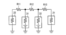
- FIG. 2 is a diagram schematically showing an example of an equivalent circuit of a vehicle power supply device.
- FIG. 2 an example of a connection relationship between the main power storage device 31, the sub power storage device 32, the first load 21, and the second load 22 is shown.
- wirings connecting the main power storage device 31, the sub power storage device 32, the first load 21 and the second load 22 are indicated by resistors R11 to R13, and the generator 1, the starter 11, and the relay boxes 41 and 42 are connected.
- the junction box 43 is not shown. 2
- the internal resistance of the main power storage device 31 and the sub power storage device 32 is also shown, and the first load 21 and the second load 22 are also shown by resistance.
- the resistor R11 is connected between the other end of the main power storage device 31 and the other end of the second load 22, and the resistor R12 is connected between the other end of the main power storage device 31 and the other end of the sub power storage device 32,
- the resistor R ⁇ b> 13 is connected between the other end of the sub power storage device 32 and the other end of the first load 21.
- the resistors R12 and R13 correspond to the wiring L1
- the resistor R13 corresponds to the wiring L2
- the resistor R11 corresponds to the wiring L3
- the resistors R11 and R12 correspond to the wiring L4.
- the resistance value of the wiring L2 (resistance value of the resistor R13) is smaller than the resistance value of the wiring L1 (the combined resistance value of the resistors R12 and R13). That is, the sub power storage device 32 is connected to the first load 21 by a wire having a smaller resistance value than the wire between the main power storage device 31 and the first load 21.
- the resistance value of the wiring L4 (the combined resistance value of the resistors R11 and R12) is larger than the resistance value of the wiring L3 (the resistance value of the resistor R11). That is, the sub power storage device 32 is connected to the second load 22 by a wire having a resistance value larger than that of the wire between the main power storage device 31 and the second load 22.
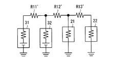
- FIG. 3 is shown as a comparative example.
- the resistor R11 ′ is connected between the other end of the main power storage device 31 and the other end of the sub power storage device 32, and the resistor R12 ′ is connected to the other end of the sub power storage device 32 and the other end of the first load 21.
- the resistor R 13 ′ is connected between the other end of the first load 21 and the other end of the second load 22.
- the voltage drop caused by the internal resistance of the main power storage device 31 and the sub power storage device 32 due to the current flowing through the second load 22 is considered.
- the main power storage device 31 is connected to the second load 22 by wires having a large resistance value (resistances R11 ′ to R13 ′), and the sub power storage device 32 is a wire having a small resistance value (resistance R12 ′). , R13 ′) to the second load 22. Therefore, from the viewpoint of the magnitude relation of the resistance value of the wiring, the current flowing from the sub power storage device 32 to the second load 22 is larger than the current flowing from the main power storage device 31 to the second load 22. Therefore, a voltage drop generated in sub power storage device 32 is large.
- the main power storage device 31 is connected to the first load 21 by wires having a large resistance value (resistances R11 ′ and R12 ′), and the sub power storage device is connected by a wire having a small resistance value (resistance R12 ′). Connected. Therefore, first load 21 is more susceptible to voltage fluctuations in sub power storage device 32 than voltage fluctuations in main power storage device 31.
- the first load 21 is susceptible to voltage fluctuations of the sub power storage device 32 in which the voltage drop due to the current to the second load 22 is large. Therefore, according to the comparative example, the power supply voltage applied to the first load 21 is greatly reduced.
- main power storage device 31 is connected to second load 22 with a small resistance value wiring (resistance R11), and sub power storage device 32 is a large resistance value wiring (resistance R11). , R12) and connected to the second load 22. Therefore, from the viewpoint of the magnitude relation of the resistance value of the wiring, the current flowing from the sub power storage device 32 to the second load 22 is smaller than the current flowing from the main power storage device 31 to the second load 22. Therefore, the voltage drop generated in sub power storage device 32 is small.
- the main power storage device 31 is connected to the first load 21 by a large resistance value wiring (resistances R12, R13), and the sub power storage device is connected by a small resistance value wiring (resistance R13). Is done. Therefore, first load 21 is more susceptible to voltage fluctuations in sub power storage device 32 than voltage fluctuations in main power storage device 31.
- the first load 21 is susceptible to the voltage fluctuation of the sub power storage device 32 in which the voltage drop due to the current to the second load 22 is small. Therefore, a drop in the power supply voltage applied to the first load 21 can be suppressed as compared with the comparative example. According to this, a load having a small allowable value for a decrease in the power supply voltage can be adopted as the first load 21.
- the in-vehicle ECU has a small allowable value for a decrease in the power supply voltage, and thus the in-vehicle ECU can be used as the first load 21.
- the starter 11 is employed as the second load 22. Even after the engine is stopped to perform idling stop, power is supplied to the first load 21 (vehicle-mounted ECU). When power is supplied to the second load 22 (starter 11) to start the engine, a relatively large current flows through the second load 22. In this case, although a voltage drop occurs in main power storage device 31 and sub power storage device 32, as described above, a decrease in power supply voltage applied to first load 21 can be suppressed. Therefore, it is possible to prevent the operation of the first load 21 from being interrupted when the engine is started from the idling stop state.
- the internal resistance value of the sub power storage device 32 is desirably smaller than the internal resistance value of the main power storage device 31.
- the voltage drop caused by the same current is smaller than that of the main power storage device 31 having a large internal resistance value. Therefore, the voltage drop in sub power storage device 32 is smaller than the voltage drop in main power storage device 31.
- the voltage drop in the sub power storage device 32 due to the current to the second load 22 can be further reduced. Therefore, it is possible to further suppress a decrease in the power supply voltage to the first load 21 due to the current to the second load 22.
- ⁇ Current of first load 21 and second load 22> The maximum value of the current flowing through the second load 22 is larger than the maximum value of the current flowing through the first load 21. That is, the secondary power storage device 32 having a small internal resistance is connected to the second load 22 through which a large current can flow with a larger resistance value.
- an in-vehicle ECU is employed as the first load 21, and a steering motor or starter 11 is employed as the second load 22.
- the voltage drop generated in the main power storage device 31 and the sub power storage device 32 increases as the current flowing through each increases. That is, the voltage drop generated in main power storage device 31 and sub power storage device 32 is larger when current flows through second load 22.
- the sub power storage device 32 having a small internal resistance is connected to the second load 22, and the wiring between the main power storage device 31 and the second load 22 is used. It is desirable to connect with a wiring having a larger resistance value. This is because the current flowing through the sub power storage device 32 can be reduced. Therefore, the voltage drop generated in the sub power storage device 32 can be reduced, and the voltage drop to the first load 21 can be suppressed.
- the first load 21 connected to the sub power storage device 32 with a small internal resistance by a wiring having a small resistance value is a small current load
- the main power storage device 31 with a large internal resistance has a small resistance value.
- the main power storage device 31, the second load 22, and the relay box 41 are disposed on the engine room ER ⁇ b> 1 side in front of the vehicle, and the sub power storage device 32, the first load 21, the relay box 42, and the junction box 43. Is disposed on the side of the passenger compartment CR1 behind the engine room ER1.
- the relay box 41 connects the main power storage device 31 to the second load 22 on the engine room ER1 side, and the relay box 42 connects the sub power storage device 32 to the junction box 43 and thus the second load 22 on the vehicle cabin CR1 side. .
- the main power storage device 31 is connected to the second load 22 on the same engine room ER1 side as the second load 22, and therefore it is easy to connect them with a short wiring.
- the sub power storage device 32 is connected to the first load 21 on the same cabin CR1 side as the first load 21, it is easy to connect them with a short wiring.
- the relay boxes 41 and 42 are provided on the engine room ER1 side and the vehicle compartment CR1 side, respectively, and are connected to each other by the wiring L12. Although engine room ER1 and vehicle compartment CR1 are partitioned by a partition plate, wiring L12 passes through the partition plate.
- the main power storage device 31 and the first load 21 are connected to each other while being positioned on the engine room ER1 side and the vehicle compartment CR1 side, respectively. Therefore, they are connected by a relatively long wiring.
- the sub power storage device 32 and the second load 22 are also connected by a relatively long wiring.
Landscapes
- Engineering & Computer Science (AREA)
- Power Engineering (AREA)
- Mechanical Engineering (AREA)
- Manufacturing & Machinery (AREA)
- Chemical & Material Sciences (AREA)
- Chemical Kinetics & Catalysis (AREA)
- Electrochemistry (AREA)
- General Chemical & Material Sciences (AREA)
- Charge And Discharge Circuits For Batteries Or The Like (AREA)
Abstract
第2負荷への電流に起因した第1負荷への電源電圧の低下を抑制する車載用電源装置を提供する。第1配線は第1負荷と主蓄電装置とを接続する。第2配線は第1負荷と副蓄電装置とを接続する。第2配線の抵抗値は第1配線の抵抗値よりも小さい。第3配線は第2負荷と主蓄電装置とを接続する。第4配線は第2負荷と副蓄電装置とを接続する。第4配線の抵抗値は第3配線の抵抗値よりも大きい。
Description
この発明は、車載用電源装置に関する。
特許文献1には、バッテリと蓄電部とを有する車両用電源装置が記載されている。バッテリおよび蓄電部は発電機によって充電され、負荷へと電源を供給する。バッテリと負荷との間にはスイッチが設けられている。また、このスイッチを制御する制御回路も設けられている。
制御回路にも、バッテリおよび蓄電部から給電することが考えらえる。この構造において、負荷に電流が流れることによってバッテリおよび蓄電部の電圧が低下すると、制御回路へ与えられる電源電圧も低下する。この電源電圧が、制御回路の電圧下限値を下回ると、制御回路が動作不能となる。よって、このような電源電圧の低下は望ましくない。
より一般化して説明すると、2つの蓄電装置から第1負荷および第2負荷へ給電する構造において、第2負荷への電流に起因して第1負荷の電源電圧が大きく低下することは望ましくない。
そこで本願は、第2負荷への電流に起因した第1負荷への電源電圧の低下を抑制する車載用電源装置を提供することを目的とする。
車載用電源装置は、第1負荷と第1蓄電装置とを接続する第1配線と、前記第1負荷と第2蓄電装置とを接続し、前記第1配線よりも小さい抵抗値を有する第2配線と、第2負荷と、前記第1蓄電装置とを接続する第3配線と、前記第2負荷と前記第2蓄電装置とを接続し、前記第3配線よりも大きい抵抗値を有する第4配線とを備える。
車載用電源装置によれば、第2負荷への電流に起因した第1負荷の電源電圧の低下を抑制することができる。
<車載用電源装置の構成>
図1は、車両に搭載される車載用電源装置100の構成の一例を概略的に示す図である。図1の例示では、発電機1およびスタータ11が設けられている。スタータ11は不図示のエンジンを始動するためのモータであり、図1では「ST」と表示されている。発電機1は例えばオルタネータであり、図1では「ALT」と表示されている。発電機1は、車両を駆動させる駆動力に基づいて発電して、直流電圧を出力する。この駆動力は例えばエンジンによって得ることができる。
図1は、車両に搭載される車載用電源装置100の構成の一例を概略的に示す図である。図1の例示では、発電機1およびスタータ11が設けられている。スタータ11は不図示のエンジンを始動するためのモータであり、図1では「ST」と表示されている。発電機1は例えばオルタネータであり、図1では「ALT」と表示されている。発電機1は、車両を駆動させる駆動力に基づいて発電して、直流電圧を出力する。この駆動力は例えばエンジンによって得ることができる。
図1の例示では、発電機1およびスタータ11は、例えばリレーボックス41を介して主蓄電装置31に接続されている。リレーボックス41は、自身に接続される構成の相互間の接続/非接続を適宜に選択する。図1ではリレーボックス41は「R/B」と表示されている。図1の例示では、リレーボックス41は、リレーボックス42および第2負荷22にも接続されており、発電機1、スタータ11、主蓄電装置31、第2負荷22およびリレーボックス42の相互間の接続/非接続を適宜に選択する。主蓄電装置31は、リレーボックス41を介して発電機1によって充電される。主蓄電装置31には例えば鉛蓄電池が採用される。
図1の例示では、発電機1には、例えばリレーボックス41,42を介して、副蓄電装置32が接続される。リレーボックス42は自身に接続される構成の相互間の接続/非接続を選択し、図1では「R/B」と表示されている。リレーボックス42は副蓄電装置32にも接続されており、リレーボックス41、副蓄電装置32およびジャンクションボックス43の相互間の接続/非接続を選択する。副蓄電装置32には例えばリチウムイオン電池、ニッケル水素電池またはキャパシタを採用できる。この副蓄電装置32は、リレーボックス41,42を介して、発電機1および主蓄電装置31によって充電される。
主蓄電装置31は、例えばリレーボックス41,42およびジャンクションボックス43を介して、第1負荷21とも接続される。第1負荷21は例えば車載ECU(Electronic Control Unit)である。ジャンクションボックス43は自身に接続される構成の相互間の接続/非接続を適宜に選択し、図1では「J/B」と表示されている。ジャンクションボックス43はリレーボックス42と第1負荷21との間の接続/非接続を適宜に選択する。なおリレーボックス41,42およびジャンクションボックス43には、適宜にリレーが設けられており、さらに、ヒューズが設けられていてもよい。
主蓄電装置31はリレーボックス41,42およびジャンクションボックス43を介して第1負荷21に給電し、副蓄電装置32はリレーボックス42およびジャンクションボックス43を介して第1負荷21に給電する。
主蓄電装置31には、例えばリレーボックス41を介して、第2負荷22が接続されている。第2負荷22は例えばステアリング用モータである。なお図1の例示では、スタータ11は第2負荷22とは別の構成として示されているものの、第2負荷22として、スタータ11を採用しても構わない。主蓄電装置31はリレーボックス41を介して第2負荷22に給電し、副蓄電装置32はリレーボックス41,42を介して第2負荷22に給電する。
図1の例示では、リレーボックス41と主蓄電装置31とは配線L11によって互いに接続され、リレーボックス41,42は配線L12によって互いに接続され、リレーボックス42とジャンクションボックス43とは配線L13によって互いに接続され、ジャンクションボックス43と第1負荷21とは配線L14によって互いに接続される。以下では、配線L11~L14を纏めて配線L1とも呼ぶ。この配線L1は第1負荷21と主蓄電装置31とを互いに接続する。
リレーボックス42と副蓄電装置32は配線L15によって接続される。以下では、配線L13~L15を纏めて配線L2とも呼ぶ。この配線L2は副蓄電装置32と第1負荷21とを互いに接続する。
リレーボックス41と第2負荷22とは配線L16によって互いに接続される。以下では、配線L11,L16を纏めて配線L3とも呼ぶ。この配線L3は主蓄電装置31と第2負荷22とを互いに接続する。また以下では、配線L12,L15,L16を纏めて配線L4とも呼ぶ。この配線L4は副蓄電装置32と第2負荷22とを互いに接続する。
配線L1~L4は車載電源用の配線群を形成する。これらの配線L1~L4は例えばワイヤーハーネスであり、その抵抗値はリレーボックス41,42およびジャンクションボックス43の抵抗値に比べて大きい。例えば配線L1~L4の抵抗値はリレーボックス41,42およびジャンクションボックス43の10~100倍程度である。したがって、各経路の抵抗値としては、主として配線L1~L4の抵抗値を考慮すればよい。
本実施の形態では、第1負荷21と副蓄電装置32とを互いに接続する配線L2(L13~L15)の抵抗値は、第1負荷21と主蓄電装置31とを互いに接続する配線L1(L11~L14)の抵抗値よりも小さい。図1の例示では、第1負荷21からリレーボックス42までの配線L13,L14は、配線L1(L11~L14),L2(L13~L15)の両方に含まれるので、配線L1,L2の抵抗値の大小関係は、配線L11,L12の合成抵抗値と、配線L15の抵抗値とで決定される。したがって、配線L15の抵抗値を配線L11,L12の合成抵抗値よりも小さく設定することで、配線L2の抵抗値を配線L1の抵抗値よりも小さくできる。
また、第2負荷22と副蓄電装置32とを互いに接続する配線L4(L12,L15,L16)の抵抗値は、第2負荷22と主蓄電装置31とを互いに接続する配線L3(L11,L16)の抵抗値よりも大きい。図1の例示では、第2負荷22からリレーボックス41までの配線L16は、配線L3(L11,L16),L4(L12,L15,L16)の両方に含まれるので、配線L3,L4の抵抗値の大小関係は、配線L11の抵抗値と、配線L12,L15の合成抵抗値とで決定される。したがって、配線L12,L15の合成抵抗値を配線L11の抵抗値よりも大きく設定することで、配線L4の抵抗値を配線L3の抵抗値よりも大きくできる。
配線L11,L12,L15の抵抗値を長さで把握すると、例えば、各抵抗値を一辺とする三角形を描ける場合、配線L11,L12,L15は上述の条件を満足する。また例えば、配線L12の抵抗値>>配線L11の抵抗値、および、配線L12の抵抗値>>配線L15の抵抗値が成立するときにも、上述の条件は満足する。
図2は、車両用電源装置の等価回路の一例を概略的に示す図である。図2の例示では、主蓄電装置31、副蓄電装置32、第1負荷21および第2負荷22の接続関係の一例が示される。図2では、主蓄電装置31、副蓄電装置32、第1負荷21および第2負荷22を相互に接続する配線を抵抗R11~R13で示し、また発電機1、スタータ11、リレーボックス41,42およびジャンクションボックス43は図示を省略している。また図2の例示では、主蓄電装置31および副蓄電装置32の内部抵抗も示し、第1負荷21および第2負荷22も抵抗で示している。
図2の例示では、第1負荷21、第2負荷22、主蓄電装置31および副蓄電装置32の各々の一端は接地されている。抵抗R11は主蓄電装置31の他端と第2負荷22の他端との間に接続され、抵抗R12は主蓄電装置31の他端と副蓄電装置32の他端との間に接続され、抵抗R13は副蓄電装置32の他端と第1負荷21の他端との間に接続されている。抵抗R12,R13は配線L1に相当し、抵抗R13は配線L2に相当し、抵抗R11は配線L3に相当し、抵抗R11,R12は配線L4に相当する。
図2の例示では、配線L2の抵抗値(抵抗R13の抵抗値)は配線L1の抵抗値(抵抗R12,R13の合成抵抗値)よりも小さい。つまり、副蓄電装置32は、主蓄電装置31と第1負荷21との間の配線よりも小さい抵抗値を有する配線で、第1負荷21と接続されている。
また配線L4の抵抗値(抵抗R11,R12の合成抵抗値)は配線L3の抵抗値(抵抗R11の抵抗値)よりも大きい。つまり、副蓄電装置32は、主蓄電装置31と第2負荷22との間の配線よりも大きい抵抗値を有する配線で、第2負荷22と接続されている。
かかる構造の利点を説明するために、比較例として図3を示す。比較例では、抵抗R11’は主蓄電装置31の他端と副蓄電装置32の他端との間に接続され、抵抗R12’は副蓄電装置32の他端と第1負荷21の他端との間に接続され、抵抗R13’は第1負荷21の他端と第2負荷22の他端との間に接続されている。
これによれば、実施の形態と同様に、第1負荷21と副蓄電装置32との間の抵抗値(=抵抗R12’の抵抗値)は、第1負荷21と主蓄電装置31との間の抵抗値(=抵抗R11’,R12’の合成抵抗値)よりも小さい。しかしながら、本実施の形態とは異なって、第2負荷22と副蓄電装置32との間の抵抗値(=抵抗R12’,R13’の合成抵抗値)も、第2負荷22と主蓄電装置31との間の抵抗値(抵抗R11~R13’の合成抵抗値)よりも小さくなっている。
次に、本実施の形態および比較例において、第2負荷22に流れる電流に起因して、主蓄電装置31および副蓄電装置32の内部抵抗で生じる電圧降下について考慮する。比較例(図3参照)では、主蓄電装置31は大きい抵抗値の配線(抵抗R11’~R13’)で第2負荷22に接続され、副蓄電装置32は小さい抵抗値の配線(抵抗R12’,R13’)で第2負荷22に接続される。よって配線の抵抗値の大小関係という観点では、副蓄電装置32から第2負荷22へと流れる電流は、主蓄電装置31から第2負荷22へと流れる電流に対して、大きくなる。したがって、副蓄電装置32に生じる電圧降下は大きい。
しかも比較例では、第1負荷21に対して、主蓄電装置31は大きな抵抗値の配線(抵抗R11’,R12’)で接続され、副蓄電装置は小さい抵抗値の配線(抵抗R12’)で接続される。よって第1負荷21は、主蓄電装置31の電圧変動よりも副蓄電装置32の電圧変動を受けやすい。
以上のように、比較例においては、第1負荷21は、第2負荷22への電流による電圧降下が大きい副蓄電装置32の電圧変動を受けやすい。よって、比較例によれば、第1負荷21へ印加する電源電圧の低下が大きい。
一方で、本実施の形態(図2参照)では、主蓄電装置31は小さい抵抗値の配線(抵抗R11)で第2負荷22に接続され、副蓄電装置32は大きい抵抗値の配線(抵抗R11,R12)で第2負荷22に接続される。よって配線の抵抗値の大小関係という観点では、副蓄電装置32から第2負荷22へと流れる電流は、主蓄電装置31から第2負荷22へと流れる電流に対して、小さくなる。したがって、副蓄電装置32に生じる電圧降下は小さい。
また本実施の形態でも、第1負荷21に対して、主蓄電装置31は大きな抵抗値の配線(抵抗R12,R13)で接続され、副蓄電装置は小さい抵抗値の配線(抵抗R13)で接続される。よって第1負荷21は、主蓄電装置31の電圧変動よりも副蓄電装置32の電圧変動を受けやすい。
以上のように、本実施の形態によれば比較例とは異なって、第1負荷21は、第2負荷22への電流による電圧降下が小さい副蓄電装置32の電圧変動を受けやすい。よって、比較例に比べて、第1負荷21へ印加する電源電圧の低下を抑制できる。これによれば、電源電圧の低下についての許容値が小さい負荷を第1負荷21として採用することができる。例えば、車載ECUは電源電圧の低下についての許容値が小さいところ、このような車載ECUを第1負荷21として採用することができるのである。
一例として、第2電流に大きな電流が流れる場合を説明する。例えば第2負荷22としてスタータ11を採用する。アイドリングストップを行うためにエンジンを停止した後にも、第1負荷21(車載ECU)には給電が行われている。そして、エンジンを始動すべく、第2負荷22(スタータ11)への給電を行うと、第2負荷22に比較的大きな電流が流れる。この場合、主蓄電装置31および副蓄電装置32には電圧降下が発生するものの、上述の通り、第1負荷21へ印加される電源電圧の低下は抑制できる。よって、アイドリングストップ状態からエンジンを始動するときに、第1負荷21の動作が中断されることを抑制できる。
<蓄電装置の内部抵抗>
例えば副蓄電装置32の内部抵抗値は主蓄電装置31の内部抵抗値よりも小さいことが望ましい。内部抵抗値の小さな副蓄電装置32においては、内部抵抗値の大きな主蓄電装置31に比べて、同じ電流に起因する電圧降下が小さい。よって、副蓄電装置32における電圧降下は主蓄電装置31の電圧降下に比べて小さい。
例えば副蓄電装置32の内部抵抗値は主蓄電装置31の内部抵抗値よりも小さいことが望ましい。内部抵抗値の小さな副蓄電装置32においては、内部抵抗値の大きな主蓄電装置31に比べて、同じ電流に起因する電圧降下が小さい。よって、副蓄電装置32における電圧降下は主蓄電装置31の電圧降下に比べて小さい。
したがって、第2負荷22への電流に起因した副蓄電装置32における電圧降下を更に低減することができる。したがって、第2負荷22への電流に起因した第1負荷21への電源電圧の低下を更に抑制できる。
<第1負荷21および第2負荷22の電流>
第2負荷22を流れる電流の最大値は、第1負荷21に流れる電流の最大値よりも大きい。つまり、大きな電流が流れ得る第2負荷22に対して、内部抵抗の小さい副蓄電装置32がより大きい抵抗値で接続される。例えば第1負荷21として車載ECUを採用し、第2負荷22としてステアリング用モータまたはスタータ11を採用する。
第2負荷22を流れる電流の最大値は、第1負荷21に流れる電流の最大値よりも大きい。つまり、大きな電流が流れ得る第2負荷22に対して、内部抵抗の小さい副蓄電装置32がより大きい抵抗値で接続される。例えば第1負荷21として車載ECUを採用し、第2負荷22としてステアリング用モータまたはスタータ11を採用する。
さて、主蓄電装置31および副蓄電装置32に生じる電圧降下は、それぞれに流れる電流が大きいほど大きい。つまり、第2負荷22に電流が流れた方が、主蓄電装置31および副蓄電装置32に生じる電圧降下は大きい。そして第1負荷21への電圧低下を抑制するには、このような第2負荷22に対して、内部抵抗の小さな副蓄電装置32を、主蓄電装置31と第2負荷22との間の配線よりも大きな抵抗値の配線で接続することが望ましい。これにより、副蓄電装置32に流れる電流を小さくできるからである。よって、副蓄電装置32に生じる電圧降下を低減でき、第1負荷21への電圧低下を抑制できるのである。
以上のように、内部抵抗の小さい副蓄電装置32に対して小さい抵抗値の配線で接続される第1負荷21を小電流負荷とし、内部抵抗の大きい主蓄電装置31に対して小さい抵抗値の配線で接続される第2負荷22を大電流負荷とすることによって、その逆に比べて、第1負荷21への電源電圧の低下を抑制するのである。
<配置>
図1の例示では、主蓄電装置31、第2負荷22およびリレーボックス41は、車両の前方のエンジンルームER1側に配置され、副蓄電装置32、第1負荷21、リレーボックス42およびジャンクションボックス43は、エンジンルームER1の後方の車室CR1側に配置される。
図1の例示では、主蓄電装置31、第2負荷22およびリレーボックス41は、車両の前方のエンジンルームER1側に配置され、副蓄電装置32、第1負荷21、リレーボックス42およびジャンクションボックス43は、エンジンルームER1の後方の車室CR1側に配置される。
そして、リレーボックス41はエンジンルームER1側において主蓄電装置31を第2負荷22に接続し、リレーボックス42は車室CR1側において副蓄電装置32をジャンクションボックス43、ひいては第2負荷22に接続する。このように、主蓄電装置31は第2負荷22と同じエンジンルームER1側で第2負荷22に接続されるので、これらを短い配線で接続しやすい。同様に、副蓄電装置32は第1負荷21と同じ車室CR1側で第1負荷21に接続されるので、これらを短い配線で接続しやすい。
また、リレーボックス41,42はそれぞれエンジンルームER1側および車室CR1側に設けられつつ、配線L12によって互いに接続されている。なおエンジンルームER1および車室CR1は仕切り板によって区画されているものの、配線L12はこの仕切り板を貫通する。
リレーボックス41,42が互いに接続されることにより、主蓄電装置31と第1負荷21とは、それぞれエンジンルームER1側および車室CR1側に位置しつつ、互いに接続される。よって、これらは比較的に長い配線で接続される。同様に、副蓄電装置32および第2負荷22も比較的に長い配線で接続される。
したがって、図1の配置によれば、上述の抵抗値の関係を満足しやすいのである。
上記各実施形態及び各変形例で説明した各構成は、相互に矛盾しない限り適宜組み合わせることができる。
以上のようにこの発明は詳細に説明されたが、上記した説明は、すべての局面において、例示であって、この発明がそれに限定されるものではない。例示されていない無数の変形例が、この発明の範囲から外れることなく想定され得るものと解される。
21 第1負荷
22 第2負荷
31 主蓄電装置
32 副蓄電装置
L11~L16 配線
100 車載用電源装置
22 第2負荷
31 主蓄電装置
32 副蓄電装置
L11~L16 配線
100 車載用電源装置
Claims (3)
- 車載用電源装置であって、
第1負荷と第1蓄電装置とを接続する第1配線と、
前記第1負荷と第2蓄電装置とを接続し、前記第1配線よりも小さい抵抗値を有する第2配線と、
第2負荷と前記第1蓄電装置とを接続する第3配線と、
前記第2負荷と前記第2蓄電装置とを接続し、前記第3配線よりも大きい抵抗値を有する第4配線と
を備える、車載用電源装置。 - 請求項1に記載の車載用電源装置であって、
前記第2蓄電装置の内部抵抗は前記第1蓄電装置の内部抵抗よりも小さい、車載用電源装置。 - 請求項2に記載の車載用電源装置であって、
前記第2負荷に流れる電流の最大値は、前記第1負荷に流れる電流の最大値よりも大きい、車載用電源装置。
Priority Applications (2)
| Application Number | Priority Date | Filing Date | Title |
|---|---|---|---|
| US15/762,770 US20180265022A1 (en) | 2015-09-25 | 2016-09-06 | In-vehicle power supply device |
| CN201680053298.XA CN108028540A (zh) | 2015-09-25 | 2016-09-06 | 车载用电源装置 |
Applications Claiming Priority (2)
| Application Number | Priority Date | Filing Date | Title |
|---|---|---|---|
| JP2015-188201 | 2015-09-25 | ||
| JP2015188201A JP2017061261A (ja) | 2015-09-25 | 2015-09-25 | 車載用電源装置 |
Publications (1)
| Publication Number | Publication Date |
|---|---|
| WO2017051697A1 true WO2017051697A1 (ja) | 2017-03-30 |
Family
ID=58386530
Family Applications (1)
| Application Number | Title | Priority Date | Filing Date |
|---|---|---|---|
| PCT/JP2016/076063 Ceased WO2017051697A1 (ja) | 2015-09-25 | 2016-09-06 | 車載用電源装置 |
Country Status (4)
| Country | Link |
|---|---|
| US (1) | US20180265022A1 (ja) |
| JP (1) | JP2017061261A (ja) |
| CN (1) | CN108028540A (ja) |
| WO (1) | WO2017051697A1 (ja) |
Citations (4)
| Publication number | Priority date | Publication date | Assignee | Title |
|---|---|---|---|---|
| JP2010184538A (ja) * | 2009-02-10 | 2010-08-26 | Kawasaki Heavy Ind Ltd | 低床式電気車両 |
| JP2010247556A (ja) * | 2009-04-10 | 2010-11-04 | Fujitsu Ten Ltd | エコラン制御装置 |
| JP2014110709A (ja) * | 2012-12-03 | 2014-06-12 | Sanyo Electric Co Ltd | 車両用電源装置 |
| JP2015012684A (ja) * | 2013-06-28 | 2015-01-19 | 三洋電機株式会社 | 電源装置 |
Family Cites Families (15)
| Publication number | Priority date | Publication date | Assignee | Title |
|---|---|---|---|---|
| JP3578656B2 (ja) * | 1999-03-04 | 2004-10-20 | 矢崎総業株式会社 | 電源供給装置 |
| JP2004338577A (ja) * | 2003-05-16 | 2004-12-02 | Hitachi Ltd | 車両用電力供給装置及び電力供給方法 |
| US7235898B1 (en) * | 2003-10-23 | 2007-06-26 | Yazaki North America, Inc. | Vehicle power distribution node with redundant power supply |
| JP4575069B2 (ja) * | 2004-07-30 | 2010-11-04 | 矢崎総業株式会社 | 車両用電源重畳多重通信システム |
| US7267090B2 (en) * | 2005-11-21 | 2007-09-11 | Gm Global Technology Operations, Inc. | Method of starting a hybrid vehicle |
| JP2010207061A (ja) * | 2009-03-06 | 2010-09-16 | Denso Corp | 車両用電源システム |
| EP2272722B1 (en) * | 2009-07-01 | 2015-04-08 | Denso Corporation | Power source apparatus for vehicle |
| JP5460727B2 (ja) * | 2009-10-16 | 2014-04-02 | 三菱電機株式会社 | 車両用電源システム |
| JP5494498B2 (ja) * | 2010-02-03 | 2014-05-14 | 株式会社デンソー | 車載電源装置 |
| JP5605320B2 (ja) * | 2011-06-28 | 2014-10-15 | 株式会社オートネットワーク技術研究所 | 車両用電源装置 |
| US20130266826A1 (en) * | 2012-03-13 | 2013-10-10 | Maxwell Technologies, Inc. | Ultracapacitor/battery combination and bus bar system |
| JP2015076957A (ja) * | 2013-10-08 | 2015-04-20 | 株式会社オートネットワーク技術研究所 | 電源装置 |
| JP6111967B2 (ja) * | 2013-10-08 | 2017-04-12 | 株式会社オートネットワーク技術研究所 | 電源システム |
| JP2015074310A (ja) * | 2013-10-08 | 2015-04-20 | 株式会社オートネットワーク技術研究所 | 車両用電源装置 |
| JP2015104277A (ja) * | 2013-11-27 | 2015-06-04 | 株式会社オートネットワーク技術研究所 | 変圧装置 |
-
2015
- 2015-09-25 JP JP2015188201A patent/JP2017061261A/ja active Pending
-
2016
- 2016-09-06 WO PCT/JP2016/076063 patent/WO2017051697A1/ja not_active Ceased
- 2016-09-06 US US15/762,770 patent/US20180265022A1/en not_active Abandoned
- 2016-09-06 CN CN201680053298.XA patent/CN108028540A/zh active Pending
Patent Citations (4)
| Publication number | Priority date | Publication date | Assignee | Title |
|---|---|---|---|---|
| JP2010184538A (ja) * | 2009-02-10 | 2010-08-26 | Kawasaki Heavy Ind Ltd | 低床式電気車両 |
| JP2010247556A (ja) * | 2009-04-10 | 2010-11-04 | Fujitsu Ten Ltd | エコラン制御装置 |
| JP2014110709A (ja) * | 2012-12-03 | 2014-06-12 | Sanyo Electric Co Ltd | 車両用電源装置 |
| JP2015012684A (ja) * | 2013-06-28 | 2015-01-19 | 三洋電機株式会社 | 電源装置 |
Also Published As
| Publication number | Publication date |
|---|---|
| JP2017061261A (ja) | 2017-03-30 |
| US20180265022A1 (en) | 2018-09-20 |
| CN108028540A (zh) | 2018-05-11 |
Similar Documents
| Publication | Publication Date | Title |
|---|---|---|
| CN103874927B (zh) | 用于多电压车载电网的诊断装置、多电压车载电网以及用于运行多电压车载电网的方法 | |
| JP6662178B2 (ja) | 車載電源用のスイッチ装置 | |
| JP5655720B2 (ja) | 絶縁不良診断装置 | |
| JP5776678B2 (ja) | 電力制御部を備える車両 | |
| JP6623937B2 (ja) | リレー装置及び電源装置 | |
| CN105392985B (zh) | 汽车电路网络中的开关系统 | |
| JP6844611B2 (ja) | 電源システム及びその制御方法 | |
| JP2017516442A (ja) | 基準搭載電源回路網を特に安全関連サブ回路網に接続する装置 | |
| CN104349931B (zh) | 用于汽车的车载电网 | |
| DE102011005729A1 (de) | Fahrzeugenergiesystem | |
| WO2016009614A1 (ja) | 車両用電源システム | |
| JP2016107879A (ja) | 自動車用電源装置 | |
| JP2014015133A (ja) | 車両用電源装置 | |
| JP2016107877A (ja) | 車両用電源システム | |
| JP2016007994A (ja) | 車両用電源システム | |
| JP6263615B2 (ja) | 端子窪みに組み込まれた始動電流制限器 | |
| JP4799641B2 (ja) | エンジン始動装置 | |
| WO2017051697A1 (ja) | 車載用電源装置 | |
| JP2015042509A (ja) | ハイブリッド車用電源装置 | |
| WO2017183512A1 (ja) | 車載電源用のスイッチ装置および車載用電源システム | |
| JP2017177824A (ja) | 車両用電源装置 | |
| JP2016174475A (ja) | 蓄電システム | |
| JP2016213968A (ja) | 電源供給装置 | |
| US9688149B2 (en) | Voltage stabilization apparatus | |
| JP2017074900A (ja) | 車載用電源装置および車載用電源システム |
Legal Events
| Date | Code | Title | Description |
|---|---|---|---|
| 121 | Ep: the epo has been informed by wipo that ep was designated in this application |
Ref document number: 16848485 Country of ref document: EP Kind code of ref document: A1 |
|
| WWE | Wipo information: entry into national phase |
Ref document number: 15762770 Country of ref document: US |
|
| NENP | Non-entry into the national phase |
Ref country code: DE |
|
| 122 | Ep: pct application non-entry in european phase |
Ref document number: 16848485 Country of ref document: EP Kind code of ref document: A1 |