WO2017047294A1 - 動力伝達装置 - Google Patents
動力伝達装置 Download PDFInfo
- Publication number
- WO2017047294A1 WO2017047294A1 PCT/JP2016/073550 JP2016073550W WO2017047294A1 WO 2017047294 A1 WO2017047294 A1 WO 2017047294A1 JP 2016073550 W JP2016073550 W JP 2016073550W WO 2017047294 A1 WO2017047294 A1 WO 2017047294A1
- Authority
- WO
- WIPO (PCT)
- Prior art keywords
- power transmission
- elastic
- transmission device
- torsion springs
- flywheel
- Prior art date
- Legal status (The legal status is an assumption and is not a legal conclusion. Google has not performed a legal analysis and makes no representation as to the accuracy of the status listed.)
- Ceased
Links
Images


Classifications
-
- F—MECHANICAL ENGINEERING; LIGHTING; HEATING; WEAPONS; BLASTING
- F16—ENGINEERING ELEMENTS AND UNITS; GENERAL MEASURES FOR PRODUCING AND MAINTAINING EFFECTIVE FUNCTIONING OF MACHINES OR INSTALLATIONS; THERMAL INSULATION IN GENERAL
- F16F—SPRINGS; SHOCK-ABSORBERS; MEANS FOR DAMPING VIBRATION
- F16F15/00—Suppression of vibrations in systems; Means or arrangements for avoiding or reducing out-of-balance forces, e.g. due to motion
- F16F15/10—Suppression of vibrations in rotating systems by making use of members moving with the system
- F16F15/12—Suppression of vibrations in rotating systems by making use of members moving with the system using elastic members or friction-damping members, e.g. between a rotating shaft and a gyratory mass mounted thereon
- F16F15/131—Suppression of vibrations in rotating systems by making use of members moving with the system using elastic members or friction-damping members, e.g. between a rotating shaft and a gyratory mass mounted thereon the rotating system comprising two or more gyratory masses
- F16F15/133—Suppression of vibrations in rotating systems by making use of members moving with the system using elastic members or friction-damping members, e.g. between a rotating shaft and a gyratory mass mounted thereon the rotating system comprising two or more gyratory masses using springs as elastic members, e.g. metallic springs
- F16F15/134—Wound springs
-
- F—MECHANICAL ENGINEERING; LIGHTING; HEATING; WEAPONS; BLASTING
- F16—ENGINEERING ELEMENTS AND UNITS; GENERAL MEASURES FOR PRODUCING AND MAINTAINING EFFECTIVE FUNCTIONING OF MACHINES OR INSTALLATIONS; THERMAL INSULATION IN GENERAL
- F16F—SPRINGS; SHOCK-ABSORBERS; MEANS FOR DAMPING VIBRATION
- F16F15/00—Suppression of vibrations in systems; Means or arrangements for avoiding or reducing out-of-balance forces, e.g. due to motion
- F16F15/10—Suppression of vibrations in rotating systems by making use of members moving with the system
- F16F15/12—Suppression of vibrations in rotating systems by making use of members moving with the system using elastic members or friction-damping members, e.g. between a rotating shaft and a gyratory mass mounted thereon
- F16F15/131—Suppression of vibrations in rotating systems by making use of members moving with the system using elastic members or friction-damping members, e.g. between a rotating shaft and a gyratory mass mounted thereon the rotating system comprising two or more gyratory masses
- F16F15/133—Suppression of vibrations in rotating systems by making use of members moving with the system using elastic members or friction-damping members, e.g. between a rotating shaft and a gyratory mass mounted thereon the rotating system comprising two or more gyratory masses using springs as elastic members, e.g. metallic springs
- F16F15/134—Wound springs
- F16F15/1343—Wound springs characterised by the spring mounting
-
- F—MECHANICAL ENGINEERING; LIGHTING; HEATING; WEAPONS; BLASTING
- F16—ENGINEERING ELEMENTS AND UNITS; GENERAL MEASURES FOR PRODUCING AND MAINTAINING EFFECTIVE FUNCTIONING OF MACHINES OR INSTALLATIONS; THERMAL INSULATION IN GENERAL
- F16F—SPRINGS; SHOCK-ABSORBERS; MEANS FOR DAMPING VIBRATION
- F16F15/00—Suppression of vibrations in systems; Means or arrangements for avoiding or reducing out-of-balance forces, e.g. due to motion
- F16F15/10—Suppression of vibrations in rotating systems by making use of members moving with the system
- F16F15/12—Suppression of vibrations in rotating systems by making use of members moving with the system using elastic members or friction-damping members, e.g. between a rotating shaft and a gyratory mass mounted thereon
- F16F15/131—Suppression of vibrations in rotating systems by making use of members moving with the system using elastic members or friction-damping members, e.g. between a rotating shaft and a gyratory mass mounted thereon the rotating system comprising two or more gyratory masses
- F16F15/139—Suppression of vibrations in rotating systems by making use of members moving with the system using elastic members or friction-damping members, e.g. between a rotating shaft and a gyratory mass mounted thereon the rotating system comprising two or more gyratory masses characterised by friction-damping means
-
- F—MECHANICAL ENGINEERING; LIGHTING; HEATING; WEAPONS; BLASTING
- F16—ENGINEERING ELEMENTS AND UNITS; GENERAL MEASURES FOR PRODUCING AND MAINTAINING EFFECTIVE FUNCTIONING OF MACHINES OR INSTALLATIONS; THERMAL INSULATION IN GENERAL
- F16F—SPRINGS; SHOCK-ABSORBERS; MEANS FOR DAMPING VIBRATION
- F16F15/00—Suppression of vibrations in systems; Means or arrangements for avoiding or reducing out-of-balance forces, e.g. due to motion
- F16F15/30—Flywheels
-
- Y—GENERAL TAGGING OF NEW TECHNOLOGICAL DEVELOPMENTS; GENERAL TAGGING OF CROSS-SECTIONAL TECHNOLOGIES SPANNING OVER SEVERAL SECTIONS OF THE IPC; TECHNICAL SUBJECTS COVERED BY FORMER USPC CROSS-REFERENCE ART COLLECTIONS [XRACs] AND DIGESTS
- Y10—TECHNICAL SUBJECTS COVERED BY FORMER USPC
- Y10T—TECHNICAL SUBJECTS COVERED BY FORMER US CLASSIFICATION
- Y10T74/00—Machine element or mechanism
- Y10T74/21—Elements
- Y10T74/2121—Flywheel, motion smoothing-type
- Y10T74/2128—Damping using swinging masses, e.g., pendulum type, etc.
-
- Y—GENERAL TAGGING OF NEW TECHNOLOGICAL DEVELOPMENTS; GENERAL TAGGING OF CROSS-SECTIONAL TECHNOLOGIES SPANNING OVER SEVERAL SECTIONS OF THE IPC; TECHNICAL SUBJECTS COVERED BY FORMER USPC CROSS-REFERENCE ART COLLECTIONS [XRACs] AND DIGESTS
- Y10—TECHNICAL SUBJECTS COVERED BY FORMER USPC
- Y10T—TECHNICAL SUBJECTS COVERED BY FORMER US CLASSIFICATION
- Y10T74/00—Machine element or mechanism
- Y10T74/21—Elements
- Y10T74/2121—Flywheel, motion smoothing-type
- Y10T74/2131—Damping by absorbing vibration force [via rubber, elastomeric material, etc.]
Definitions
- the present invention relates to a power transmission device, and more particularly to a power transmission device capable of attenuating torque fluctuation between an engine and a transmission.
- the conventional power transmission device includes an input rotating portion (28), an output rotating portion (33), a first elastic portion (29, 32), an intermediate member (31), and an inertia mass portion (53, 54). And a second elastic portion (55).
- the first elastic portion elastically connects the input rotation portion and the output rotation portion in the rotation direction.
- the intermediate member connects the first elastic portions in series.
- the second elastic part connects the intermediate member and the inertial mass part.
- the inertia mass part (53, 54) and the second elastic part (55) function as a dynamic damper device (34).
- the first elastic part is an elastic part for torque transmission
- the second elastic part is an elastic part for a dynamic damper.
- the power transmission device can attenuate torque fluctuations between the engine and the transmission.
- the power transmission device includes an input rotation unit, an output rotation unit, an elastic unit, an inertia mass unit, and an engagement unit. Torque is input to the input rotating unit.
- the output rotating unit can rotate relative to the input rotating unit.
- the elastic portion elastically connects the input rotation portion and the output rotation portion in the rotation direction.
- the inertial mass part is movable in the rotation direction.
- the engaging part engages with the elastic part and the inertial mass part. The engaging part operates the elastic part by relative rotation of the input rotating part and the output rotating part and movement of the inertial mass part.
- torque fluctuation can be attenuated when the engaging portion operates the elastic portion by the relative rotation of the input rotating portion and the output rotating portion. Further, torque fluctuation can be attenuated even when the engaging portion operates the elastic portion by the movement of the inertial mass portion.
- torque fluctuations can be attenuated without specially preparing an elastic part for operating the inertial mass part. That is, in this power transmission device, torque fluctuation can be attenuated even when the inertial mass unit is moved by only the elastic part that elastically connects the input rotary part and the output rotary part. That is, in this power transmission device, the inertial mass body can be operated with a simple configuration, and downsizing can be achieved.
- the engaging portion can compress the elastic portion by relative rotation between the input rotating portion and the output rotating portion. Further, the engaging portion can bend the elastic portion by movement of the inertial mass portion.
- the engaging portion can compress the elastic portion by the relative rotation of the input rotating portion and the output rotating portion, torque fluctuation can be attenuated by compressive deformation of the elastic portion.
- the engaging part can bend the elastic part by the movement of the inertial mass part, the torque fluctuation can be attenuated by the bending deformation of the elastic part.
- torque fluctuations can be attenuated by utilizing the compressive deformation and bending deformation of the elastic portion.
- torque fluctuation can be attenuated even when the inertial mass unit is moved by only the elastic part that elastically connects the input rotary part and the output rotary part. That is, in this power transmission device, the inertial mass body can be operated with a simple configuration, and downsizing can be achieved.
- the engaging portion is slidably engaged with the inertia mass portion.
- the engaging part swings with respect to the inertial mass part.
- the elastic portion can be bent and deformed by the swinging of the engaging portion.
- the engaging portion is in contact with the elastic portion. For this reason, an elastic part can be reliably pressed and compressed and deformed by an engaging part. Further, the elastic portion can be stably bent and deformed by the engaging portion.
- the power transmission device further includes a positioning portion.
- the positioning portion positions the engaging portion in the radial direction. In this case, since the radial movement of the engaging portion can be restricted by the positioning portion, the elastic portion can be reliably compressed and deformed, and can be stably bent and deformed.
- the positioning portion further positions the elastic portion in the radial direction.
- the elastic portion in a state where the elastic portion is held in the radial direction by the positioning portion, the elastic portion can be reliably compressed and deformed, and can be stably bent and deformed.
- the inertial mass portion is disposed on the radially inner side of the engagement portion. Therefore, a power transmission device can be further reduced in size.
- the inertial mass portion is formed in an annular shape. Thereby, an inertial mass part can be stably operated in a rotation direction.
- the elastic part includes a first elastic part and a second elastic part.
- the second elastic part operates in series with the first elastic part.
- the engaging portion is disposed between the first elastic portion and the second elastic portion.
- the inertial mass body can be operated with a simple configuration, and downsizing can be achieved.
- the inertial mass body can be operated with a simple configuration in the power transmission device. Moreover, in this invention, a power transmission device can be reduced in size.
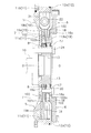
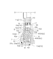
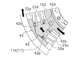
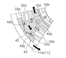
- the partial front view (except for the 2nd flywheel) of the power transmission device by one embodiment of the present invention Sectional drawing of the power transmission device in a cutting line AOB. Sectional drawing of the power transmission device in cutting line OC. The figure for demonstrating the operation
- [overall structure] 1, 2A, and 2B are a front view and a cross-sectional view of a flywheel assembly 2 according to an embodiment of the present invention.
- the flywheel assembly 2 is an example of a power transmission device.
- the OO line is the rotation axis.
- the engine is disposed on the left side of FIGS. 2A and 2B, and the transmission is disposed on the right side of FIGS. 2A and 2B.
- the engine is arranged on the left side of FIGS. 2A and 2B, and the clutch device is arranged on the right side of FIGS. 2A and 2B.
- the engine, transmission, and clutch device are not shown.
- the flywheel assembly 2 is disposed between the engine and the transmission. Torque is input to the flywheel assembly 2 from the engine. Torque output from the flywheel assembly 2 is transmitted to the clutch device.
- the flywheel assembly 2 can attenuate torque fluctuations between the engine and the transmission. As shown in FIGS. 1, 2A, and 2B, the flywheel assembly 2 includes a first flywheel 5 (an example of an input rotation unit), a second flywheel 6 (an example of an output rotation unit), a damper, A mechanism 7 and a hysteresis torque generating mechanism 8 are provided.
- the first flywheel 5 is a member to which power from the engine is input. Power from the engine is input to the first flywheel 5.
- the first flywheel 5 is fixed to the crankshaft 10 of the engine.
- the first flywheel 5 includes a first plate 11, a second plate 12, and a support member 13.
- the first plate 11 has a disc part 11a having a hole at the center of rotation, and a first cylindrical part 11b extending from the outer peripheral end of the disc part 11a to the transmission side.
- the inner peripheral portion of the first plate 11 is fixed to the crankshaft 10 together with the support member 13 by a fixing member such as a bolt 24.
- a power transmission portion 11 c is provided on the outer peripheral portion of the first plate 11.
- the power transmission unit 11 c is a part that transmits power from the engine to the damper mechanism 7.
- the power transmission unit 11c can press the spring seat 21 (first spring seat 31 described later) of the damper mechanism 7.
- the power transmission unit 11c is formed in a stepped shape.
- the first spring seat 31 can come into contact with the wall portion of the power transmission portion 11c.
- the first spring seat 31 is pressed by the wall portion of the power transmission portion 11 c, and power from the engine is transmitted from the first plate 11 to the damper mechanism 7.
- the first spring seat 31 that comes into contact with the wall portion of the step-shaped power transmission portion 11c is the first spring seat 31 that can come into contact with a protruding portion 19b (described later) of the second flywheel 6.
- the second plate 12 is an annular member and has a disk portion 12a having a hole at the center of rotation.
- the disc portion 12a of the second plate 12 is disposed so as to face the disc portion 11a of the first plate 11 in the axial direction.
- the outer peripheral end portion of the disc portion 12 a is welded to the axial tip portion of the first cylindrical portion 11 b of the first plate 11.
- the support member 13 is a cylindrical member. As described above, the support member 13 is fixed to the crankshaft 10 together with the first plate 11 by a fixing member such as a bolt 24.
- the second flywheel 6 is disposed so as to be rotatable relative to the first flywheel 5. Specifically, as shown in FIGS. 2A and 2B, the second flywheel 6 is rotatably supported by the support member 13 via a bearing 17 disposed on the outer periphery of the support member 13.
- the second flywheel 6 has a main body plate 18 and a flange plate 19.
- the main body plate 18 is an annular member.
- the main body plate 18 is disposed on the transmission side (clutch device side) of the second plate 12.
- the main body plate 18 is provided with a second cylindrical portion 18a extending from the inner peripheral end to the engine side.
- the second cylindrical portion 18a is fixed to the flange plate 19 by a fixing member such as a bolt 20.
- the bearing 17 is arrange
- the main body plate 18 is rotatably supported by the support member 13 by the bearing 17.
- the flange plate 19 is disposed between the first plate and the second plate in the axial direction.
- the flange plate 19 is formed in an annular shape.
- the flange plate 19 includes an annular portion 19a, a plurality of (for example, two) protruding portions 19b, and a plurality of (for example, two) cutout portions 19c. is doing.
- FIG. 1 shows only one of the two notches 19c.
- the annular portion 19 a is a portion formed in an annular shape on the inner peripheral side of the flange plate 19.
- the annular portion 19 a is fixed to the main body plate 18 by a fixing member such as a bolt 20.
- the protruding portion 19b is a portion protruding radially outward from the annular portion 19a.
- the protruding portion 19b is provided on the annular portion 19a.
- the protrusion part 19b is integrally formed in the outer peripheral part of the cyclic
- the protruding portions 19b are integrally formed on the outer peripheral portion of the annular portion 19a with an interval of substantially 180 degrees in the circumferential direction.
- the notch portion 19c is a portion provided between the protruding portions 19b adjacent in the circumferential direction.
- the notch portion 19c is provided in the annular portion 19a.
- the notch 19c is comprised from the circumferential direction side part of the protrusion part 19b, and the outer peripheral part of the cyclic
- a plurality of torsion springs 22 and a plurality of spring seats 21 are arranged in the notch 19c.
- the damper mechanism 7 is a mechanism that elastically connects the first flywheel 5 and the second flywheel 6. Specifically, the damper mechanism 7 is a mechanism that elastically connects the first plate 11 and the second plate 12 in the rotation direction.
- the damper mechanism 7 is disposed between the first flywheel 5 and the second flywheel 6. As shown in FIG. Specifically, the damper mechanism 7 is disposed between the first plate 11 and the second plate 12 in the axial direction.
- the damper mechanism 7 includes a plurality (for example, eight) of torsion springs 22 (an example of an elastic portion), a plurality (for example, ten) of spring seats 21, and an inertia. And a member 23 (an example of an inertial mass unit).
- FIG. 2A and 2B show four torsion springs 22 in eight torsion springs 22 and five spring seats 21 in ten spring seats 21.
- FIG. 2A and 2B show four torsion springs 22 in eight torsion springs 22 and five spring seats 21 in ten spring seats 21.
- the plurality of torsion springs 22 are for elastically operating the first flywheel 5 and the second flywheel 6 in the rotational direction. As shown in FIGS. 1, 2A, and 2B, a plurality of torsion springs 22, for example, six torsion springs 22 are accommodated in a notch 19c of the second flywheel 6 (flange plate 19). The six torsion springs 22 are arranged side by side in the circumferential direction at the notch 19c (see FIG. 1). The four torsion springs 22 (22a, 22b, 22c) in the six torsion springs 22 are arranged in series. The two torsion springs 22 (22d, 22e) in the six torsion springs 22 are arranged on the inner periphery of the torsion springs 22 (22a, 22b).
- the four torsion springs 22 among the six torsion springs 22 include a first torsion spring 22a (an example of a first elastic portion) and a second torsion spring 22b ( An example of the second elastic portion) and two third torsion springs 22c are included.
- the first to third torsion springs 22a, 22b, 22c are arranged in series and operate in series.
- a fourth torsion spring 22d (an example of a first elastic portion) is disposed on the inner periphery of the first torsion spring 22a. Further, a fifth torsion spring 22e (an example of a second elastic portion) is disposed on the inner peripheral portion of the second torsion spring 22b.
- the first torsion spring 22a and the second torsion spring 22b are a pair of torsion springs arranged on both sides of a second spring seat 41 (described later) in the circumferential direction.
- the fourth torsion spring 22d and the fifth torsion spring 22e are a pair of torsion springs disposed on both sides of a second spring seat 41 (described later) in the circumferential direction.
- the two third torsion springs 22c are other torsion springs in the six torsion springs 22 except for the first and second torsion springs 22a and 22b and the fourth and fifth torsion springs 22d and 22e.
- the six torsion springs 22 are provided in each notch. It arranges in part 19c.
- the six torsion springs 22 are a pair of protrusions adjacent in the circumferential direction in the second flywheel 6 (flange plate 19). 19b.
- spring seat 21 connects each of a plurality of torsion springs 22 arranged in the peripheral direction in each notch 19c.
- the spring seat 21 holds both ends of the torsion spring 22 so that the torsion spring 22 can be pressed.
- the spring seat 21 is restricted from moving radially outward by the first flywheel 5. Specifically, the spring seat 21 is slidable on the inner peripheral portion of the first cylindrical portion 11 b of the first plate 11 and is radially outwardly moved by the first cylindrical portion 11 b of the first plate 11. Movement is restricted.
- the plurality of spring seats 21 are arranged in the notch 19c of the second flywheel 6 (flange plate 19). Further, the spring seat 21 is disposed at both ends of each torsion spring 22 (both ends of the first to fifth torsion springs 22a, 22b, 22c, 22d, and 22e).
- the plurality of spring seats 21 include a plurality (for example, eight) of first spring seats 31 and a plurality (for example, two) of second spring seats 41.
- the four first spring seats 31 and the one second spring seat 41 are disposed in each notch 19c.
- four first spring seats 31 and one second spring seat 41 are arranged between a pair of protrusions 19b adjacent in the circumferential direction on the second flywheel 6 (flange plate 19).
- the first spring seat 31 is disposed between the third torsion springs 22c adjacent in the circumferential direction and between the third torsion spring 22c and the first torsion spring 22a (fourth torsion spring 22d) adjacent in the circumferential direction. Is done.
- the first spring seat 31 is disposed between the protruding portion 19b of the second flywheel 6 (flange plate 19) and the third torsion spring 22c, which are adjacent in the circumferential direction.
- the 1st spring seat 31 is arrange
- the first spring seat 31 arranged in this way holds the end portions of the first to fifth torsion springs 22a, 22b, 22c, 22d, and 22e, and the first to fourth torsion springs 22a, 22b, 22c, Each of 22d and 22e can be pressed.
- the second spring seat 41 is disposed between the first and fourth torsion springs 22 a and 22 d and the second and fifth torsion springs 22 b and 22 e that are adjacent in the circumferential direction.
- the spring seat at the 8 o'clock position of the timepiece corresponds to the second spring seat 41.
- the second spring seat 41 arranged in this way holds the end portions of the first and fourth torsion springs 22a and 22d and the end portions of the second and fifth torsion springs 22b and 22e.
- the second spring seat 41 can press the first and fourth torsion springs 22a and 22d and the second and fifth torsion springs 22b and 22e, respectively.
- the second spring seat 41 has an engaging portion 42 and a positioning portion 43.
- the engaging portion 42 engages with the torsion spring 22 (first and second torsion springs 22a and 22b, fourth and fifth torsion springs 22d and 22e) and the inertia member 23.
- the engaging portion 42 can operate the first and fourth torsion springs 22a and 22d and the second and fifth torsion springs 22b and 22e by the relative rotation of the first flywheel 5 and the second flywheel 6. is there.
- the engaging portion 42 can operate the first and fourth torsion springs 22a and 22d and the second and fifth torsion springs 22b and 22e by the movement of the inertia member 23 in the rotation direction.
- the engaging portion 42 causes the first and fourth torsion springs 22a and 22d and the second and fifth torsion springs 22b and 22e to be rotated by the relative rotation of the first flywheel 5 and the second flywheel 6. Compressible.
- the engaging portion 42 can bend the first and fourth torsion springs 22a and 22d and the second and fifth torsion springs 22b and 22e by the movement of the inertia member 23 in the rotation direction.
- the engaging portion 42 is engaged with the end portions of the first and fourth torsion springs 22a and 22d and the end portions of the second and fifth torsion springs 22b and 22e. Further, the engaging portion 42 is engaged with the inertia member 23 so as to be swingable.
- the engaging portion 42 includes a first main body portion 42a, a first contact portion 42b, a first spring holding portion 42c, a first bending portion 42d, and a connecting portion 42e. Yes.
- the first main body portion 42a is disposed between the first torsion spring 22a and the second torsion spring 22b.
- the first contact portion 42b is provided in the first main body portion 42a.
- the first contact portion 42b contacts the end portions of the first and fourth torsion springs 22a and 22d and the end portions of the second and fifth torsion springs 22b and 22e.
- the 1st contact part 42b can press the 1st and 4th torsion springs 22a and 22d and the 2nd and 5th torsion springs 22b and 22e.
- the first spring holding portion 42c engages with the first and fourth torsion springs 22a and 22d and the second and fifth torsion springs 22b and 22e. Accordingly, the first spring holding portion 42c holds the first and fourth torsion springs 22a and 22d and the second and fifth torsion springs 22b and 22e.
- the first spring holding portion 42c has a pair of shaft portions 42f and a pair of flange portions 42g.
- Each of the pair of shaft portions 42f is provided on the first contact portion 42b so as to protrude from the first contact portion 42b.
- One of the pair of shaft portions 42f is disposed on the inner peripheral portion of the fourth torsion spring 22d.
- the other of the pair of shaft portions 42f is disposed on the inner peripheral portion of the fifth torsion spring 22e.
- the pair of flange portions 42g are provided on the first main body portion 42a so as to protrude from the first main body portion 42a on the inner peripheral side of the first main body portion 42a.
- One of the pair of flange portions 42g holds the inner peripheral side of the first torsion spring 22a.
- the other of the pair of flange portions 42g holds the inner peripheral side of the second torsion spring 22b.
- the first curved portion 42 d is a portion that engages with the positioning portion 43.
- 42 d of 1st curved parts are provided in the outer peripheral part of the 1st main-body part 42a.
- 42 d of 1st curved parts are formed in the outer peripheral part of the 1st main-body part 42a in convex shape to radial direction outward.
- the connecting portion 42e is a portion connected to the inertia member 23.
- the connection part 42e is provided in the inner peripheral part of the 1st main-body part 42a.
- the connecting portion 42e has an arm portion 42h.
- the arm portion 42h is provided on the first main body portion 42a so as to protrude radially inward from the first main body portion 42a.
- a first connection hole 42i is provided at the tip of the arm portion 42h.
- the first connecting hole portion 42i is for connecting the engaging portion 42 to the inertia member 23 so as to be swingable.
- the first connection hole 42i is disposed to face the second connection hole 102d (described later) of the inertia member 23. In this state, the swing shaft portion 26 is disposed in the first connection hole portion 42i and the second connection hole portion 102d. Thereby, the engaging part 42 is attached to the inertia member 23 so as to be swingable.
- the positioning part 43 positions the engaging part 42 and the torsion spring 22 (first and fourth torsion springs 22a and 22d and second and fifth torsion springs 22b and 22e) in the radial direction.
- the positioning portion 43 positions the engaging portion 42 in the radial direction so that the engaging portion 42 can swing with respect to the inertia member 23.
- the positioning portion 43 positions the engaging portion 42 in the radial direction so that the engaging portion 42 can press the first and fourth torsion springs 22a and 22d and the second and fifth torsion springs 22b and 22e. .
- the positioning portion 43 is restricted from moving radially outward by the first flywheel 5 (the first cylindrical portion 11b of the first plate 11).
- the positioning portion 43 is disposed between the first tubular portion 11b of the first plate 11 and the engaging portion 42 in the radial direction.
- the positioning part 43 is arrange
- the positioning portion 43 includes a second main body portion 43a, a concave portion 43b, and a second spring holding portion 43c.
- the second main body portion 43 a is restricted from moving radially outward by the first cylindrical portion 11 b of the first plate 11.
- the recess 43b is provided in the second main body 43a.
- the concave portion 43b is formed in a concave shape so as to correspond to the shape of the first curved portion 42d of the engaging portion 42.
- the first curved portion 42d of the engaging portion 42 is disposed in the concave portion 43b.
- the second spring holding portion 43c holds the outer peripheral side of the end portion of the first torsion spring 22a and the outer peripheral side of the end portion of the second torsion spring 22b.
- the inertia member 23 is arrange
- the inertia member 23 is formed in an annular shape. As shown in FIGS. 2A and 2B, the inertia member 23 includes a pair of inertia rings 102. Each of the pair of inertia rings 102 is disposed to face each other in the axial direction. The pair of inertia rings 102 have the same configuration.
- each of the pair of inertia rings 102 includes a second contact portion 102a (see the upper view of the line OO in FIG. 2A) and a step portion 102b (upper view of the line OO in FIG. 2A). ), A facing portion 102c (see the lower view of the line OO in FIG. 2A), and a second connecting hole portion 102d (see FIG. 2B).
- the pair of second contact portions 102a contact each other in the axial direction.
- the pair of stepped portions 102b form a recess in a state where the pair of second contact portions 102a are in contact with each other.
- the bottom part of the notch part 19c of the flange plate 19 is arrange
- the pair of opposed portions 102c are arranged at a predetermined interval in the axial direction in a state where the pair of second contact portions 102a are in contact with each other.
- a protruding portion 19b of the flange plate 19 is disposed between the pair of opposed portions 102c.
- the pair of second connection holes 102d are for connecting the engaging portions 42 to the pair of inertia rings 102 in a swingable manner.
- the pair of second connecting hole portions 102d are provided separately for the pair of opposed portions 102c.
- a connecting portion 42e of the engaging portion 42 is disposed between the pair of facing portions 102c in the axial direction. In this state, the engaging portion 42 is inserted into the first connecting hole portion 42i and the pair of second connecting hole portions 102d and fixed to the second connecting hole portion 102d.
- a pair of inertia rings 102 are swingably mounted.
- the pair of inertia rings 102 are positioned in the radial direction by the second flywheel 6. Specifically, as shown in FIG. 2A, a pair of inertias are obtained by bringing the inner peripheral part of one inertia ring 102 into contact with the second cylindrical part 18 a of the second flywheel 6 (main body plate 18). The ring 102 is positioned in the radial direction.
- the hysteresis torque generating mechanism 8 is disposed between the inner peripheral portion of the first plate 11 and the axial direction of the flange portion 13 a formed on the outer peripheral portion of the support member 13.
- the hysteresis torque generating mechanism 8 includes a plurality of annular plate members and a cone spring. In this hysteresis torque generating mechanism 8, frictional resistance (hysteresis torque) is generated in the rotational direction by the relative rotation of the first flywheel 5 and the second flywheel 6.
- the damper mechanism 7 is operated by the relative rotation of the first flywheel 5 and the second flywheel 6. Specifically, when power is transmitted from the power transmission unit 11 c of the first flywheel 5 to the damper mechanism 7, the plurality of torsion springs 22 are pressed via the plurality of spring seats 21. As a result, the plurality of torsion springs 22 are compressed and deformed.
- a plurality of torsion springs 22 expand and contract. Thereby, it is possible to attenuate torsional vibration when torque fluctuation occurs.
- the inertia member 23 can be operated.
- the engagement portion 42 of the second spring seat 41 swings with respect to the inertia member 23 due to the movement of the inertia member 23. (See FIGS. 3A and 3B).
- the first and fourth torsion springs 22a and 22d and the second and fifth torsion springs 22b and 22e with which the engaging part 42 engages are bent by the swinging of the engaging part 42.
- the engaging portion 42 of the second spring seat 41 is in relation to the end portions of the first and fourth torsion springs 22a and 22d and the end portions of the second and fifth torsion springs 22b and 22e. It works as follows.
- the outer peripheral side of one of the first and fourth torsion springs 22a and 22d and the second and fifth torsion springs 22b and 22e is connected to the engaging portion 42 (first contact spring).
- the first and fourth torsion springs 22a and 22d and the inner peripheral side of the other end of the second and fifth torsion springs 22b and 22e are pressed by the contact portion 42b). It is pressed by the contact part 42b).
- the first and fourth torsion springs 22a and 22d and the inner peripheral side of one end of the second and fifth torsion springs 22b and 22e press the engaging portion 42 (first contact portion 42b). To do. At this time, the first and fourth torsion springs 22a and 22d and the other outer peripheral side of the second and fifth torsion springs 22b and 22e are connected to the engaging portion 42 (first contact portion 42b). ). As described above, the engaging portion 42 acts on the first and fourth torsion springs 22a and 22d and the second and fifth torsion springs 22b and 22e, whereby the first and fourth torsion springs 22a and 22d. Then, the second and fifth torsion springs 22b and 22e are bent and deformed.
- the engaging portion 42 of the second spring seat 41 is engaged so that the first and fourth torsion springs 22a and 22d and the second and fifth torsion springs 22b and 22e can be pressed, and the inertia member. This is realized by connecting to 23 in a swingable manner.
- the torsional vibration at the time of torque fluctuation can be attenuated.
- the inertia member 23 is operated and the first and fourth torsion springs 22a and 22d and the second and fifth torsion springs 22b and 22e are bent and deformed, the torsional vibration at the time of occurrence of torque fluctuation can be further damped.
- FIG. 4 is a diagram showing the relationship between the input rotational speed input from the engine to the first flywheel 5 and the rotational speed fluctuation of the second flywheel 6.
- a solid line is the case where the flywheel assembly 2 has the inertia member 23.
- the broken line is the case where the flywheel assembly 2 does not have the inertia member 23.
- the flywheel assembly 2 can effectively attenuate torsional vibration when torque fluctuation occurs.
- 4 is a portion where the torsional vibration at the time of torque fluctuation is most effectively damped by the operation of the inertia member 23.
- the first and fourth torsion springs 22a and 22d, the second and the second torsion springs for operating the inertia member 23 as in the prior art are not prepared. Only the fifth torsion springs 22b and 22e can attenuate torsional vibrations when torque fluctuation occurs. Thus, in this flywheel assembly 2, the inertia member 23 can be operated with a simple configuration. Moreover, the flywheel assembly 2 can be reduced in size by this structure.
- the clutch device includes, for example, a lockup device and a torque converter.
- the torsion springs with which the second spring seat 41 is engaged are the first and fourth torsion springs 22a and 22d and the second and fifth torsion springs 22b and 22e. It was.
- the first and second torsion springs 22a and 22b may be the only torsion springs with which the second spring seat is engaged. In this case, the fourth and fifth torsion springs 22d and 22e are not used. Even if comprised in this way, the effect similar to the above can be acquired.
Landscapes
- Engineering & Computer Science (AREA)
- General Engineering & Computer Science (AREA)
- Physics & Mathematics (AREA)
- Acoustics & Sound (AREA)
- Aviation & Aerospace Engineering (AREA)
- Mechanical Engineering (AREA)
- Mechanical Operated Clutches (AREA)
Abstract
簡単な構成で慣性質量体を作動させることができる動力伝達装置を、提供する。本動力伝達装置(2)は、入力回転部(5)と、出力回転部(6)と、弾性部(22a,22b)と、慣性質量部(23)と、係合部(42)とを、備えている。弾性部(22a,22b)は、入力回転部(5)と出力回転部(6)とを回転方向に弾性的に連結する。慣性質量部(23)は、回転方向に移動可能である。係合部(42)は、弾性部(22a,22b)及び慣性質量部(23)に係合する。係合部(42)は、入力回転部(5)及び出力回転部(6)の相対回転と、慣性質量部(23)の移動によって、弾性部(22a,22b)を作動させる。
Description
本発明は、動力伝達装置、特に、エンジン及びトランスミッションの間においてトルクの変動を減衰可能な動力伝達装置に関する。
従来、エンジン及びトランスミッションの間においてトルクの変動を減衰可能な動力伝達装置が、開示されている(特許文献1を参照)。従来の動力伝達装置は、入力回転部(28)と、出力回転部(33)と、第1弾性部(29,32)と、中間部材(31)と、慣性質量部(53,54)と、第2弾性部(55)とを、有している。第1弾性部は、入力回転部と出力回転部とを回転方向に弾性的に連結する。中間部材は、第1弾性部を直列に連結する。第2弾性部は、中間部材及び慣性質量部を連結する。この場合、慣性質量部(53,54)及び第2弾性部(55)が、ダイナミックダンパ装置(34)として機能する。
従来の動力伝達装置では、第1弾性部がトルク伝達用の弾性部であり、第2弾性部がダイナミックダンパ用の弾性部となっている。このように動力伝達装置を構成する場合、ダイナミックダンパ装置を機能させるためには、慣性質量部だけでなく、第2弾性部も用意する必要がある。このため、動力伝達装置の構成が複雑になったり、動力伝達装置が大型化したりするという問題がある。
本発明は、上記の問題に鑑みてなされたものであって、本発明の目的は、簡単な構成で慣性質量体を作動させることができる動力伝達装置を、提供することにある。また、本発明の別の目的は、小型化できる動力伝達装置を、提供することにある。
本発明の一側面に係る動力伝達装置は、エンジン及びトランスミッションの間においてトルクの変動を減衰可能である。本動力伝達装置は、入力回転部と、出力回転部と、弾性部と、慣性質量部と、係合部とを、備えている。入力回転部には、トルクが入力される。出力回転部は、入力回転部と相対回転可能である。弾性部は、入力回転部と出力回転部とを回転方向に弾性的に連結する。慣性質量部は、回転方向に移動可能である。係合部は、弾性部及び慣性質量部に係合する。係合部は、入力回転部及び出力回転部の相対回転と、慣性質量部の移動とによって、弾性部を作動させる。
本動力伝達装置では、入力回転部及び出力回転部の相対回転によって係合部が弾性部を作動させた場合に、トルク変動を減衰できる。また、慣性質量部の移動によって係合部が弾性部を作動させた場合にも、トルク変動を減衰できる。このように、本動力伝達装置では、慣性質量部を作動させるための弾性部を特別に用意することなく、トルク変動を減衰できる。すなわち、本動力伝達装置では、入力回転部と出力回転部とを弾性的に連結する弾性部だけで、慣性質量部の移動時にもトルク変動を減衰できる。すなわち、本動力伝達装置では、簡単な構成で慣性質量体を作動させることができ、小型化を図ることができる。
本発明の別の側面に係る動力伝達装置では、係合部は、入力回転部と出力回転部との相対回転によって弾性部を圧縮可能である。また、係合部は、慣性質量部の移動によって、弾性部を曲げ可能である。
この場合、入力回転部と出力回転部との相対回転によって係合部が弾性部を圧縮可能であるので、弾性部の圧縮変形によってトルク変動を減衰できる。また、慣性質量部の移動によって係合部が弾性部を曲げ可能であるので、弾性部の曲げ変形によってトルク変動を減衰できる。このように、本動力伝達装置では、弾性部の圧縮変形及び曲げ変形を利用することによって、トルク変動を減衰できる。このように、本動力伝達装置では、入力回転部と出力回転部とを弾性的に連結する弾性部だけで、慣性質量部の移動時にもトルク変動を減衰できる。すなわち、本動力伝達装置では、簡単な構成で慣性質量体を作動させることができ、小型化を図ることができる。
本発明のさらに別の側面に係る動力伝達装置では、係合部が、慣性質量部に揺動可能に係合している。この場合、慣性質量部が回転方向に移動すると、係合部が、慣性質量部に対して揺動する。この係合部の揺動によって、弾性部を曲げ変形させることができる。
本発明のさらに別の側面に係る動力伝達装置では、係合部が、弾性部に当接している。このため、係合部によって弾性部を確実に押圧し圧縮変形させることができる。また、係合部によって弾性部を安定的に曲げ変形させることができる。
本発明のさらに別の側面に係る動力伝達装置は、位置決め部を、さらに備えている。位置決め部は、係合部を径方向に位置決めする。この場合、位置決め部によって、係合部の径方向移動を規制することができるので、弾性部を、確実に圧縮変形させることができ、且つ安定的に曲げ変形させることができる。
本発明のさらに別の側面に係る動力伝達装置では、位置決め部が、弾性部を径方向にさらに位置決めする。この場合、位置決め部によって弾性部を径方向に保持した状態で、弾性部を、確実に圧縮変形させることができ、且つ安定的に曲げ変形させることができる。
本発明のさらに別の側面に係る動力伝達装置では、慣性質量部が、係合部の径方向内側に配置される。これにより、動力伝達装置をさらに小型化できる。
本発明のさらに別の側面に係る動力伝達装置では、慣性質量部が、環状に形成されている。これにより、慣性質量部を回転方向に安定的に動作させることができる。
本発明のさらに別の側面に係る動力伝達装置では、弾性部が、第1弾性部と、第2弾性部とを、含んでいる。第2弾性部は、第1弾性部と直列に作動する。係合部は、第1弾性部及び第2弾性部の間に配置される。
このように構成しても、慣性質量部を作動させるための弾性部を特別に用意することなく、入力回転部と出力回転部とを弾性的に連結する弾性部だけで、トルク変動を減衰できる。すなわち、本動力伝達装置では、簡単な構成で慣性質量体を作動させることができ、小型化を図ることができる。
本発明では、動力伝達装置において、簡単な構成で慣性質量体を作動させることができる。また、本発明では、動力伝達装置を小型化できる。
[全体構成]
図1、図2A、及び図2Bは、本発明の一実施形態によるフライホイール組立体2の正面図及び断面図である。フライホイール組立体2は、動力伝達装置の一例である。
図1、図2A、及び図2Bは、本発明の一実施形態によるフライホイール組立体2の正面図及び断面図である。フライホイール組立体2は、動力伝達装置の一例である。
図2A及び図2Bにおいて、O-O線が回転軸線である。図2A及び図2Bの左側にエンジンが配置され、図2A及び図2Bの右側にトランスミッションが配置されている。詳細には、図2A及び図2Bの左側にエンジンが配置され、図2A及び図2Bの右側にクラッチ装置が配置されている。エンジン、トランスミッション、及びクラッチ装置は、図示していない。
[フライホイール組立体]
フライホイール組立体2は、エンジンとトランスミッションとの間に配置されている。フライホイール組立体2には、エンジンからトルクが入力される。フライホイール組立体2から出力されるトルクは、クラッチ装置に伝達される。
フライホイール組立体2は、エンジンとトランスミッションとの間に配置されている。フライホイール組立体2には、エンジンからトルクが入力される。フライホイール組立体2から出力されるトルクは、クラッチ装置に伝達される。
フライホイール組立体2は、エンジン及びトランスミッションの間においてトルクの変動を減衰可能である。図1、図2A、及び図2Bに示すように、フライホイール組立体2は、第1フライホイール5(入力回転部の一例)と、第2フライホイール6(出力回転部の一例)と、ダンパ機構7と、ヒステリシストルク発生機構8とを、備えている。
<第1フライホイール>
第1フライホイール5は、エンジンからの動力が入力される部材である。第1フライホイール5には、エンジンからの動力が入力される。第1フライホイール5は、エンジンのクランクシャフト10に固定されている。
第1フライホイール5は、エンジンからの動力が入力される部材である。第1フライホイール5には、エンジンからの動力が入力される。第1フライホイール5は、エンジンのクランクシャフト10に固定されている。
図1、図2A、及び図2Bに示すように、第1フライホイール5は、第1プレート11と、第2プレート12と、支持部材13と、を有している。
第1プレート11は、回転中心部に孔部を有する円板部11aと、円板部11aの外周端からトランスミッション側に延びる第1筒状部11bとを、有している。第1プレート11の内周部は、固定部材例えばボルト24によって、支持部材13とともに、クランクシャフト10に固定される。
第1プレート11の外周部には、動力伝達部11cが設けられている。動力伝達部11cは、エンジンからの動力をダンパ機構7に伝達する部分である。動力伝達部11cは、ダンパ機構7のスプリングシート21(後述する第1スプリングシート31)を押圧可能である。詳細には、動力伝達部11cは、動力伝達部11cは、段差状に形成されている。動力伝達部11cの壁部には、第1スプリングシート31が当接可能である。この動力伝達部11cの壁部によって第1スプリングシート31が押圧され、エンジンからの動力が、第1プレート11からダンパ機構7へと伝達される。
ここで、段差状の動力伝達部11cの壁部に当接する第1スプリングシート31は、第2フライホイール6の突出部19b(後述する)に当接可能な第1スプリングシート31である。
第2プレート12は、環状の部材であり、回転中心部に孔部を有する円板部12aを、有している。第2プレート12の円板部12aは、第1プレート11の円板部11aと軸方向に対向して配置されている。円板部12aの外周端部は、第1プレート11の第1筒状部11bの軸方向先端部に溶接されている。
支持部材13は、筒状の部材である。支持部材13は、上述したように、固定部材例えばボルト24によって、第1プレート11とともに、クランクシャフト10に固定される。
<第2フライホイール>
第2フライホイール6は、第1フライホイール5に対して相対回転可能に配置されている。具体的には、図2A及び図2Bに示すように、第2フライホイール6は、支持部材13の外周に配置された軸受17を介して、支持部材13に回転自在に支持されている。第2フライホイール6は、本体プレート18と、フランジプレート19と、を有している。
第2フライホイール6は、第1フライホイール5に対して相対回転可能に配置されている。具体的には、図2A及び図2Bに示すように、第2フライホイール6は、支持部材13の外周に配置された軸受17を介して、支持部材13に回転自在に支持されている。第2フライホイール6は、本体プレート18と、フランジプレート19と、を有している。
本体プレート18は、環状の部材である。本体プレート18は、第2プレート12のトランスミッション側(クラッチ装置側)に配置される。本体プレート18には、内周端からエンジン側に延びる第2筒状部18aが、設けられている。第2筒状部18aは、固定部材例えばボルト20によって、フランジプレート19に固定されている。第2筒状部18aの内周側には、軸受17が配置されている。この軸受17によって、本体プレート18は、支持部材13に回転自在に支持される。
フランジプレート19は、軸方向において、第1プレート及び第2プレートの間に配置されている。フランジプレート19は、環状に形成されている。
図1、図2A、及び図2Bに示すように、フランジプレート19は、環状部19aと、複数(例えば2個)の突出部19bと、複数(例えば2個)の切欠部19cとを、有している。なお、図1には、2個の切欠部19cの一方だけを示している。
環状部19aは、フランジプレート19の内周側において環状に形成された部分である。環状部19aは、固定部材例えばボルト20によって、本体プレート18に固定されている。突出部19bは、環状部19aから径方向外方に突出した部分である。突出部19bは、環状部19aに設けられている。詳細には、突出部19bは、周方向において間隔を隔てて、環状部19aの外周部に一体に形成されている。ここでは、突出部19bは、周方向に実質的に180度の間隔を隔てて、環状部19aの外周部に一体に形成されている。
切欠部19cは、周方向において隣接する突出部19bの間に設けられた部分である。切欠部19cは、環状部19aに設けられている。詳細には、切欠部19cは、突出部19bの周方向側部及び環状部19aの外周部から、構成されている。切欠部19cには、複数のトーションスプリング22及び複数のスプリングシート21(後述する)が、配置される。
<ダンパ機構>
ダンパ機構7は、第1フライホイール5及び第2フライホイール6を、弾性的に連結する機構である。詳細には、ダンパ機構7は、第1プレート11及び第2プレート12を、回転方向に弾性的に連結する機構である。
ダンパ機構7は、第1フライホイール5及び第2フライホイール6を、弾性的に連結する機構である。詳細には、ダンパ機構7は、第1プレート11及び第2プレート12を、回転方向に弾性的に連結する機構である。
図2A及び図2Bに示すように、ダンパ機構7は、第1フライホイール5及び第2フライホイール6の間に配置される。詳細には、ダンパ機構7は、軸方向において、第1プレート11及び第2プレート12の間に配置される。
図1、図2A、及び図2Bに示すように、ダンパ機構7は、複数(例えば8個)のトーションスプリング22(弾性部の一例)と、複数(例えば10個)のスプリングシート21と、イナーシャ部材23(慣性質量部の一例)とを、有している。
なお、図2A及び図2Bには、8個のトーションスプリング22の中の4個のトーションスプリング22と、10個のスプリングシート21の中の5個のスプリングシート21とを、示している。
・トーションスプリング
複数のトーションスプリング22は、第1フライホイール5及び第2フライホイール6を回転方向に弾性的に作動させるためのものである。図1、図2A、及び図2Bに示すように、複数のトーションスプリング22、例えば6個のトーションスプリング22は、第2フライホイール6(フランジプレート19)の切欠部19cに、収容される。6個のトーションスプリング22は、切欠部19cにおいて周方向に並べて配置される(図1を参照)。6個のトーションスプリング22における4個のトーションスプリング22(22a,22b,22c)は、直列に配置される。6個のトーションスプリング22における2個のトーションスプリング22(22d,22e)は、トーションスプリング22(22a,22b)の内周部に配置される。
複数のトーションスプリング22は、第1フライホイール5及び第2フライホイール6を回転方向に弾性的に作動させるためのものである。図1、図2A、及び図2Bに示すように、複数のトーションスプリング22、例えば6個のトーションスプリング22は、第2フライホイール6(フランジプレート19)の切欠部19cに、収容される。6個のトーションスプリング22は、切欠部19cにおいて周方向に並べて配置される(図1を参照)。6個のトーションスプリング22における4個のトーションスプリング22(22a,22b,22c)は、直列に配置される。6個のトーションスプリング22における2個のトーションスプリング22(22d,22e)は、トーションスプリング22(22a,22b)の内周部に配置される。
具体的には、図1に示すように、6個のトーションスプリング22の中の4個のトーションスプリング22は、第1トーションスプリング22a(第1弾性部の一例)と、第2トーションスプリング22b(第2弾性部の一例)と、2個の第3トーションスプリング22cとを、含んでいる。第1から第3トーションスプリング22a,22b,22cは、直列に配置され、直列に作動する。
第1トーションスプリング22aの内周部には、第4トーションスプリング22d(第1弾性部の一例)が配置されている。また、第2トーションスプリング22bの内周部には、第5トーションスプリング22e(第2弾性部の一例)が配置されている。
第1トーションスプリング22aと、第2トーションスプリング22bとは、周方向において第2スプリングシート41(後述する)の両側に配置される1対のトーションスプリングである。同様に、第4トーションスプリング22dと、第5トーションスプリング22eとは、周方向において第2スプリングシート41(後述する)の両側に配置される1対のトーションスプリングである。
2個の第3トーションスプリング22cは、6個のトーションスプリング22において、第1及び第2トーションスプリング22a,22b及び第4及び第5トーションスプリング22d,22eを除く他のトーションスプリングである。
本実施形態では、2個の切欠部19cがフランジプレート19に設けられているので、6個のトーションスプリング22(第1から第5トーションスプリング22a,22b,22c,22d,22e)が、各切欠部19cに配置される。言い換えると、6個のトーションスプリング22(第1から第5トーションスプリング22a,22b,22c,22d,22e)は、第2フライホイール6(フランジプレート19)において周方向に隣接する1対の突出部19bの間に、配置される。
・スプリングシート
図1に示すように、スプリングシート21は、各切欠部19cにおいて周方向に並べて配置された複数のトーションスプリング22それぞれを、連結する。スプリングシート21は、トーションスプリング22を押圧可能なように、トーションスプリング22の両端部それぞれを保持する。スプリングシート21は、第1フライホイール5によって径方向外方への移動が規制されている。詳細には、スプリングシート21は、第1プレート11の第1筒状部11bの内周部に摺動可能であり、且つ第1プレート11の第1筒状部11bによって径方向外方への移動が規制されている。
図1に示すように、スプリングシート21は、各切欠部19cにおいて周方向に並べて配置された複数のトーションスプリング22それぞれを、連結する。スプリングシート21は、トーションスプリング22を押圧可能なように、トーションスプリング22の両端部それぞれを保持する。スプリングシート21は、第1フライホイール5によって径方向外方への移動が規制されている。詳細には、スプリングシート21は、第1プレート11の第1筒状部11bの内周部に摺動可能であり、且つ第1プレート11の第1筒状部11bによって径方向外方への移動が規制されている。
複数のスプリングシート21は、第2フライホイール6(フランジプレート19)の切欠部19cに配置される。また、スプリングシート21は、各トーションスプリング22の両端部(第1から第5トーションスプリング22a,22b,22c,22d,22eの両端部)に、配置される。
複数のスプリングシート21は、複数(例えば8個)の第1スプリングシート31と、複数(例えば2個)の第2スプリングシート41とを、含んでいる。
本実施形態では、2個の切欠部19cがフランジプレート19に設けられているので、4個の第1スプリングシート31及び1個の第2スプリングシート41が、各切欠部19cに配置される。言い換えると、4個の第1スプリングシート31及び1個の第2スプリングシート41が、第2フライホイール6(フランジプレート19)において周方向に隣接する1対の突出部19bの間に、配置される。
第1スプリングシート31は、周方向において隣接する第3トーションスプリング22cの間と、周方向において隣接する第3トーションスプリング22c及び第1トーションスプリング22a(第4トーションスプリング22d)との間に、配置される。また、第1スプリングシート31は、周方向において隣接する、第2フライホイール6(フランジプレート19)の突出部19bと、第3トーションスプリング22cとの間に、配置される。さらに、第1スプリングシート31は、周方向において隣接する、第2フライホイール6(フランジプレート19)の突出部19bと、第2トーションスプリング22b(第5トーションスプリング22e)との間に、配置される。
このように配置された第1スプリングシート31は、第1から第5トーションスプリング22a,22b,22c,22d,22eそれぞれの端部を保持し、第1から第4トーションスプリング22a,22b,22c,22d,22eそれぞれを、押圧可能である。
図1に示すように、第2スプリングシート41は、周方向において隣接する第1及び第4トーションスプリング22a,22dと、第2及び第5トーションスプリング22b,22eとの間に、配置される。図1では、時計の8時の位置のスプリングシートが、第2スプリングシート41に対応している。
このように配置された第2スプリングシート41は、第1及び第4トーションスプリング22a,22dの端部と、第2及び第5トーションスプリング22b,22eの端部とを、保持する。また、第2スプリングシート41は、第1及び第4トーションスプリング22a,22dと、第2及び第5トーションスプリング22b,22eそれぞれを、押圧可能である。
第2スプリングシート41は、係合部42と、位置決め部43とを、有している。係合部42は、トーションスプリング22(第1及び第2トーションスプリング22a,22b、第4及び第5トーションスプリング22d,22e)と、イナーシャ部材23とに、係合する。
係合部42は、第1フライホイール5及び第2フライホイール6の相対回転によって、第1及び第4トーションスプリング22a,22dと、第2及び第5トーションスプリング22b,22eとを、作動可能である。また、係合部42は、イナーシャ部材23の回転方向の移動によって、第1及び第4トーションスプリング22a,22dと、第2及び第5トーションスプリング22b,22eとを、作動可能である。
詳細には、係合部42は、第1フライホイール5及び第2フライホイール6の相対回転によって、第1及び第4トーションスプリング22a,22dと、第2及び第5トーションスプリング22b,22eとを、圧縮可能である。また、係合部42は、イナーシャ部材23の回転方向の移動によって、第1及び第4トーションスプリング22a,22dと、第2及び第5トーションスプリング22b,22eを曲げ可能である。
係合部42は、第1及び第4トーションスプリング22a,22dの端部、及び第2及び第5トーションスプリング22b,22eの端部に係合している。また、係合部42は、イナーシャ部材23に対して揺動可能に係合している。
具体的には、係合部42は、第1本体部42aと、第1当接部42bと、第1スプリング保持部42cと、第1湾曲部42dと、連結部42eとを、有している。第1本体部42aは、第1トーションスプリング22a及び第2トーションスプリング22bの間に配置される。
第1当接部42bは、第1本体部42aに設けられる。第1当接部42bは、第1及び第4トーションスプリング22a,22dの端部と、第2及び第5トーションスプリング22b,22eの端部に、当接する。これにより、第1当接部42bは、第1及び第4トーションスプリング22a,22dと、第2及び第5トーションスプリング22b,22eを、押圧可能である。
第1スプリング保持部42cは、第1及び第4トーションスプリング22a,22dと、第2及び第5トーションスプリング22b,22eとに、係合する。これにより、第1スプリング保持部42cは、第1及び第4トーションスプリング22a,22dと、第2及び第5トーションスプリング22b,22eを、保持する。
具体的には、第1スプリング保持部42cは、1対の軸部42fと、1対の鍔部42gとを、有している。1対の軸部42fそれぞれは、第1当接部42bから突出するように、第1当接部42bに設けられている。1対の軸部42fの一方は、第4トーションスプリング22dの内周部に配置される。1対の軸部42fの他方は、第5トーションスプリング22eの内周部に配置される。
1対の鍔部42gは、第1本体部42aの内周側において第1本体部42aから突出するように、第1本体部42aに設けられている。1対の鍔部42gの一方は、第1トーションスプリング22aの内周側を保持する。1対の鍔部42gの他方は、第2トーションスプリング22bの内周側を保持する。
第1湾曲部42dは、位置決め部43に係合する部分である。第1湾曲部42dは、第1本体部42aの外周部に設けられている。第1湾曲部42dは、第1本体部42aの外周部において、径方向外方に凸状に形成されている。
連結部42eは、イナーシャ部材23に連結される部分である。連結部42eは、第1本体部42aの内周部に設けられている。具体的には、連結部42eは、アーム部42hを、有している。アーム部42hは、第1本体部42aから径方向内方に突出するように、第1本体部42aに設けられている。アーム部42hの先端部には、第1連結孔部42iが設けられている。第1連結孔部42iは、係合部42をイナーシャ部材23に揺動可能に連結するためのものである。第1連結孔部42iは、イナーシャ部材23の第2連結孔部102d(後述する)に対向配置される。この状態で、第1連結孔部42i及び第2連結孔部102dには、揺動軸部26が配置される。これにより、係合部42は、イナーシャ部材23に対して揺動可能に装着される。
位置決め部43は、係合部42及びトーションスプリング22(第1及び第4トーションスプリング22a,22d及び第2及び第5トーションスプリング22b,22e)を、径方向に位置決めする。
詳細には、位置決め部43は、係合部42がイナーシャ部材23に対して揺動可能なように、係合部42を径方向に位置決めする。また、位置決め部43は、係合部42が第1及び第4トーションスプリング22a,22d及び第2及び第5トーションスプリング22b,22eを押圧可能なように、係合部42を径方向に位置決めする。
図1に示すように、位置決め部43は、第1フライホイール5(第1プレート11の第1筒状部11b)によって、径方向外方への移動が規制されている。位置決め部43は、径方向において、第1プレート11の第1筒状部11bと係合部42との間に、配置されている。また、位置決め部43は、径方向において、第1プレート11の第1筒状部11bと、第1トーションスプリング22aの端部及び第2トーションスプリング22bの端部との間に、配置されている。
位置決め部43は、第2本体部43aと、凹部43bと、第2スプリング保持部43cとを、有している。第2本体部43aは、第1プレート11の第1筒状部11bによって、径方向外方への移動が規制されている。凹部43bは、第2本体部43aに設けられている。凹部43bは、係合部42の第1湾曲部42dの形状に対応するように、凹状に形成されている。凹部43bには、係合部42の第1湾曲部42dが配置される。イナーシャ部材23の移動によって係合部42が揺動すると、第1湾曲部42dは凹部43bに沿って摺動する。第2スプリング保持部43cは、第1トーションスプリング22aの端部外周側及び第2トーションスプリング22bの端部外周側を、保持する。
・イナーシャ部材
イナーシャ部材23は、回転方向に移動可能に配置されている。図1、図2A、及び図2Bに示すように、イナーシャ部材23は、複数のトーションスプリング22(第1から第5トーションスプリング22a,22b,22c,22d,22e)の径方向内方に、配置される。また、イナーシャ部材23は、複数のスプリングシート21の径方向内方に、配置される。さらに、イナーシャ部材23は、支持部材13の径方向外方に配置されている。
イナーシャ部材23は、回転方向に移動可能に配置されている。図1、図2A、及び図2Bに示すように、イナーシャ部材23は、複数のトーションスプリング22(第1から第5トーションスプリング22a,22b,22c,22d,22e)の径方向内方に、配置される。また、イナーシャ部材23は、複数のスプリングシート21の径方向内方に、配置される。さらに、イナーシャ部材23は、支持部材13の径方向外方に配置されている。
図1に示すように、イナーシャ部材23は、環状に形成されている。図2A及び図2Bに示すように、イナーシャ部材23は、1対のイナーシャリング102を含んでいる。1対のイナーシャリング102それぞれは、軸方向に互いに対向して配置される。1対のイナーシャリング102は、同じ構成である。
具体的には、1対のイナーシャリング102それぞれは、第2当接部102a(図2AにおけるO-O線の上図を参照)と、段差部102b(図2AにおけるO-O線の上図を参照)と、対向部102c(図2AにおけるO-O線の下図を参照)と、第2連結孔部102d(図2Bを参照)とを、有している。
図2Aに示すように、1対の第2当接部102aは、軸方向に互いに当接する。1対の段差部102bは、1対の第2当接部102aが当接した状態において、凹部を形成する。1対の段差部102b(凹部)には、フランジプレート19の切欠部19cの底部が、配置される。1対の対向部102cは、1対の第2当接部102aが当接した状態において、軸方向に所定の間隔を隔てて配置される。1対の対向部102cの間には、フランジプレート19の突出部19bが、配置される。
図2Bに示すように、1対の第2連結孔部102dは、係合部42を1対のイナーシャリング102に揺動可能に連結するためのものである。1対の第2連結孔部102dは、1対の対向部102cに各別に設けられている。1対の対向部102cの軸方向間には、係合部42の連結部42eが配置される。この状態において、揺動軸部26を、第1連結孔部42i及び1対の第2連結孔部102dに挿通し、且つ第2連結孔部102dに固定することによって、係合部42は、1対のイナーシャリング102に対して揺動可能に装着される。
また、1対のイナーシャリング102は、第2フライホイール6によって、径方向に位置決めされている。詳細には、図2Aに示すように、一方のイナーシャリング102の内周部を、第2フライホイール6(本体プレート18)の第2筒状部18aに当接させることによって、1対のイナーシャリング102が径方向に位置決めされている。
<ヒステリシストルク発生機構>
ヒステリシストルク発生機構8は、第1プレート11の内周部と、支持部材13の外周部に形成されたフランジ部13aとの軸方向間に、配置されている。ヒステリシストルク発生機構8は、環状の複数のプレート部材と、コーンスプリングとから構成されている。このヒステリシストルク発生機構8では、第1フライホイール5及び第2フライホイール6の相対回転によって、回転方向に摩擦抵抗(ヒステリシストルク)が発生する。
ヒステリシストルク発生機構8は、第1プレート11の内周部と、支持部材13の外周部に形成されたフランジ部13aとの軸方向間に、配置されている。ヒステリシストルク発生機構8は、環状の複数のプレート部材と、コーンスプリングとから構成されている。このヒステリシストルク発生機構8では、第1フライホイール5及び第2フライホイール6の相対回転によって、回転方向に摩擦抵抗(ヒステリシストルク)が発生する。
[動作及び特徴]
まず、エンジンからの動力が第1フライホイール5に伝達され、第1フライホイール5及び第2フライホイール6が相対回転すると、ヒステリシストルク発生機構8において摩擦抵抗(ヒステリシストルク)が発生する。
まず、エンジンからの動力が第1フライホイール5に伝達され、第1フライホイール5及び第2フライホイール6が相対回転すると、ヒステリシストルク発生機構8において摩擦抵抗(ヒステリシストルク)が発生する。
次に、第1フライホイール5及び第2フライホイール6の相対回転によって、ダンパ機構7が作動する。具体的には、第1フライホイール5の動力伝達部11cからダンパ機構7へと、動力が伝達されると、複数のスプリングシート21を介して、複数のトーションスプリング22が押圧される。これにより、複数のトーションスプリング22が、圧縮変形する。ここで、ダンパ機構7には、第1フライホイール5及び第2フライホイール6の相対回転時のトルク変動が入力されるので、複数のトーションスプリング22は、伸び縮みする。これにより、トルク変動発生時の捩り振動を減衰できる。
続いて、複数のトーションスプリング22が作動している状態において、イナーシャ部材23は作動可能である。例えば、イナーシャ部材23が第1フライホイール5の回転方向とは反対の回転方向に移動すると、イナーシャ部材23の移動によって、第2スプリングシート41の係合部42がイナーシャ部材23に対して揺動する(図3A及び図3Bを参照)。すると、この係合部42の揺動によって、係合部42が係合する第1及び第4トーションスプリング22a,22dと、第2及び第5トーションスプリング22b,22eが、曲げられる。
より具体的には、第2スプリングシート41の係合部42は、第1及び第4トーションスプリング22a,22dの端部と、第2及び第5トーションスプリング22b,22eの端部に対して、次のように作用する。
図3A及び図3Bに示すように、第1及び第4トーションスプリング22a,22dと、第2及び第5トーションスプリング22b,22eのいずれか一方の端部外周側が、係合部42(第1当接部42b)によって押圧され、且つ第1及び第4トーションスプリング22a,22dと、第2及び第5トーションスプリング22b,22eのいずれか他方の端部内周側とが、係合部42(第1当接部42b)によって押圧される。
また、第1及び第4トーションスプリング22a,22dと、第2及び第5トーションスプリング22b,22eのいずれか一方の端部内周側とが、係合部42(第1当接部42b)を押圧する。この際には、第1及び第4トーションスプリング22a,22dと、第2及び第5トーションスプリング22b,22eのいずれか他方の端部外周側とが、係合部42(第1当接部42b)を押圧する。このように、第1及び第4トーションスプリング22a,22dと、第2及び第5トーションスプリング22b,22eとに対して係合部42が作用することによって、第1及び第4トーションスプリング22a,22dと、第2及び第5トーションスプリング22b,22eとが、曲げ変形する。
上述した動作は、第2スプリングシート41の係合部42を、第1及び第4トーションスプリング22a,22dと、第2及び第5トーションスプリング22b,22eを押圧可能に係合し、且つイナーシャ部材23に揺動可能に連結することによって、実現される。
また、上述した動作時において、複数のトーションスプリング22(第1から第5トーションスプリング22a,22b,22c,22d,22e)が圧縮変形した場合、トルク変動発生時の捩り振動を減衰できる。また、イナーシャ部材23が作動し、第1及び第4トーションスプリング22a,22dと、第2及び第5トーションスプリング22b,22eが曲げ変形した場合に、トルク変動発生時の捩り振動をさらに減衰できる。
例えば、図4は、エンジンから第1フライホイール5へと入力された入力回転速度と、第2フライホイール6の回転速度変動との関係を示した図である。実線が、フライホイール組立体2が、イナーシャ部材23を有する場合のものである。一方で、破線が、フライホイール組立体2が、イナーシャ部材23を有しない場合のものである。
図4から明らかなように、本フライホイール組立体2では、トルク変動発生時の捩り振動を効果的に減衰できる。なお、図4の谷部が、イナーシャ部材23の作動によって、トルク変動発生時の捩り振動が、最も効果的に減衰されている部分である。
このように、本フライホイール組立体2では、従来技術のようにイナーシャ部材23を作動させるためのトーションスプリングを特別に用意することなく、第1及び第4トーションスプリング22a,22dと、第2及び第5トーションスプリング22b,22eだけで、トルク変動発生時の捩り振動を減衰できる。このように、本フライホイール組立体2では、簡単な構成でイナーシャ部材23を作動させることができる。また、この構成によって、フライホイール組立体2を小型化できる。
[他の実施形態]
本発明は、上述した実施形態に限定されるものではなく、本発明の範囲を逸脱することなく種々の変形又は修正が可能である。
本発明は、上述した実施形態に限定されるものではなく、本発明の範囲を逸脱することなく種々の変形又は修正が可能である。
(a)前記実施形態では、動力伝達装置の一例として、フライホイール組立体2を用いて説明を行ったが、動力伝達装置の構成は、前記実施形態に限定されるものではなく、種々の装置に適用可能である。
(b)前記実施形態では、フライホイール組立体2から出力される動力が、クラッチ装置に伝達される場合の例を示した。クラッチ装置には、例えば、ロックアップ装置及びトルクコンバータ等が、含まれる。
(c)前記実施形態では、第2スプリングシート41が係合するトーションスプリングが、第1及び第4トーションスプリング22a,22dと、第2及び第5トーションスプリング22b,22eである場合の例を示した。これに代えて、第2スプリングシートが係合するトーションスプリングが、第1及び第2トーションスプリング22a,22bだけであってもよい。この場合は、第4及び第5トーションスプリング22d,22eは、用いられない。このように構成しても、上記と同様の効果を得ることができる。
2 フライホイール組立体
5 第1フライホイール
6 第2フライホイール
7 ダンパ機構
21 スプリングシート
22 トーションスプリング
22a 第1トーションスプリング
22b 第2トーションスプリング
22d 第4トーションスプリング
22e 第5トーションスプリング
23 イナーシャ部材
41 第2スプリングシート
42 係合部
43 位置決め部
5 第1フライホイール
6 第2フライホイール
7 ダンパ機構
21 スプリングシート
22 トーションスプリング
22a 第1トーションスプリング
22b 第2トーションスプリング
22d 第4トーションスプリング
22e 第5トーションスプリング
23 イナーシャ部材
41 第2スプリングシート
42 係合部
43 位置決め部
Claims (9)
- エンジン及びトランスミッションの間においてトルクの変動を減衰可能な動力伝達装置であって、
トルクが入力される入力回転部と、
前記入力回転部と相対回転可能である出力回転部と、
前記入力回転部と前記出力回転部とを回転方向に弾性的に連結する弾性部と、
前記回転方向に移動可能な慣性質量部と、
前記弾性部及び前記慣性質量部に係合し、前記入力回転部及び前記出力回転部の相対回転と、前記慣性質量部の移動とによって、前記弾性部を作動させる係合部と、
を備える動力伝達装置。 - 前記係合部は、前記入力回転部と前記出力回転部との相対回転によって前記弾性部を圧縮可能であり、前記慣性質量部の移動によって前記弾性部を曲げ可能である、
請求項1に記載の動力伝達装置。 - 前記係合部は、前記慣性質量部に揺動可能に係合している、
請求項1又は2に記載の動力伝達装置。 - 前記係合部は、前記弾性部に当接する、
請求項1から3のいずれか1項に記載の動力伝達装置。 - 前記係合部を径方向に位置決めする位置決め部、
をさらに備える請求項1から4のいずれか1項に記載の動力伝達装置。 - 前記位置決め部は、前記弾性部を径方向にさらに位置決めする、
請求項5に記載の動力伝達装置。 - 前記慣性質量部は、前記係合部の径方向内側に配置される、
請求項1から6のいずれか1項に記載の動力伝達装置。 - 前記慣性質量部は、環状に形成されている、
請求項1から7のいずれか1項に記載の動力伝達装置。 - 前記弾性部は、第1弾性部と、前記第1弾性部と直列に作動する第2弾性部とを、含み、
前記係合部は、前記第1弾性部及び前記第2弾性部の間に配置される、
請求項1から8のいずれか1項に記載の動力伝達装置。
Priority Applications (3)
| Application Number | Priority Date | Filing Date | Title |
|---|---|---|---|
| US15/580,164 US20180142761A1 (en) | 2015-09-18 | 2016-08-10 | Power transmission device |
| CN201680050725.9A CN107923488A (zh) | 2015-09-18 | 2016-08-10 | 动力传递装置 |
| DE112016003336.2T DE112016003336T5 (de) | 2015-09-18 | 2016-08-10 | Kraftübertragungsvorrichtung |
Applications Claiming Priority (2)
| Application Number | Priority Date | Filing Date | Title |
|---|---|---|---|
| JP2015-185062 | 2015-09-18 | ||
| JP2015185062A JP6616988B2 (ja) | 2015-09-18 | 2015-09-18 | 動力伝達装置 |
Publications (1)
| Publication Number | Publication Date |
|---|---|
| WO2017047294A1 true WO2017047294A1 (ja) | 2017-03-23 |
Family
ID=58289028
Family Applications (1)
| Application Number | Title | Priority Date | Filing Date |
|---|---|---|---|
| PCT/JP2016/073550 Ceased WO2017047294A1 (ja) | 2015-09-18 | 2016-08-10 | 動力伝達装置 |
Country Status (5)
| Country | Link |
|---|---|
| US (1) | US20180142761A1 (ja) |
| JP (1) | JP6616988B2 (ja) |
| CN (1) | CN107923488A (ja) |
| DE (1) | DE112016003336T5 (ja) |
| WO (1) | WO2017047294A1 (ja) |
Citations (2)
| Publication number | Priority date | Publication date | Assignee | Title |
|---|---|---|---|---|
| JP2012117571A (ja) * | 2010-11-30 | 2012-06-21 | Aisin Aw Industries Co Ltd | ダンパスプリング及びダンパ装置 |
| JP2014206244A (ja) * | 2013-04-15 | 2014-10-30 | 株式会社エクセディ | トルクコンバータのロックアップ装置 |
Family Cites Families (4)
| Publication number | Priority date | Publication date | Assignee | Title |
|---|---|---|---|---|
| JPH11101267A (ja) * | 1997-09-29 | 1999-04-13 | Exedy Corp | ダンパー機構 |
| US7343832B2 (en) * | 2003-02-14 | 2008-03-18 | Luk Lamellen Und Kupplungsbau Beteiligungs Kg | Torsional vibration damper |
| JP5716645B2 (ja) * | 2011-11-28 | 2015-05-13 | トヨタ自動車株式会社 | 捩り振動低減装置 |
| JP6245871B2 (ja) * | 2013-06-04 | 2017-12-13 | 株式会社エクセディ | トルクコンバータのロックアップ装置 |
-
2015
- 2015-09-18 JP JP2015185062A patent/JP6616988B2/ja active Active
-
2016
- 2016-08-10 DE DE112016003336.2T patent/DE112016003336T5/de not_active Withdrawn
- 2016-08-10 WO PCT/JP2016/073550 patent/WO2017047294A1/ja not_active Ceased
- 2016-08-10 US US15/580,164 patent/US20180142761A1/en not_active Abandoned
- 2016-08-10 CN CN201680050725.9A patent/CN107923488A/zh active Pending
Patent Citations (2)
| Publication number | Priority date | Publication date | Assignee | Title |
|---|---|---|---|---|
| JP2012117571A (ja) * | 2010-11-30 | 2012-06-21 | Aisin Aw Industries Co Ltd | ダンパスプリング及びダンパ装置 |
| JP2014206244A (ja) * | 2013-04-15 | 2014-10-30 | 株式会社エクセディ | トルクコンバータのロックアップ装置 |
Also Published As
| Publication number | Publication date |
|---|---|
| US20180142761A1 (en) | 2018-05-24 |
| CN107923488A (zh) | 2018-04-17 |
| JP2017057974A (ja) | 2017-03-23 |
| JP6616988B2 (ja) | 2019-12-04 |
| DE112016003336T5 (de) | 2018-04-05 |
Similar Documents
| Publication | Publication Date | Title |
|---|---|---|
| JP6274796B2 (ja) | 自動車用のトルク伝達装置 | |
| JP6334284B2 (ja) | 動力伝達装置及びトルクコンバータのロックアップ装置 | |
| JP5705935B2 (ja) | ダンパディスク組立体 | |
| JP6653538B2 (ja) | トルク変動抑制装置、トルクコンバータ、及び動力伝達装置 | |
| JP6616662B2 (ja) | ダンパ装置 | |
| JP6541969B2 (ja) | 動力伝達装置及びトルクコンバータのロックアップ装置 | |
| JP6361644B2 (ja) | 捩り振動低減装置 | |
| JP6501295B2 (ja) | ダンパーディスク組立体 | |
| JP6714420B2 (ja) | ダンパ装置 | |
| JP6616988B2 (ja) | 動力伝達装置 | |
| JP6301158B2 (ja) | ダンパー装置 | |
| JP2008039113A (ja) | スプリングシート及びスプリング組立体 | |
| JP2018091407A (ja) | 捩り振動低減装置 | |
| JP2019090428A (ja) | ダンパディスク組立体 | |
| JP2019090428A5 (ja) | ||
| JP6387870B2 (ja) | 捩り振動低減装置 | |
| JP6587388B2 (ja) | 自動車用の動吸振装置、及びトルクコンバータのロックアップ装置 | |
| JP2018031426A (ja) | 振動低減装置 | |
| WO2018037826A1 (ja) | 振動低減装置 | |
| JP6587715B2 (ja) | 動力伝達装置及びトルクコンバータのロックアップ装置 | |
| JP4402934B2 (ja) | フレキシブルフライホイール | |
| JP2018150955A (ja) | ダンパディスク組立体 | |
| JP2005163948A (ja) | フライホイール組立体 | |
| JP2021085450A (ja) | ダンパ装置 | |
| JP2018150957A (ja) | ダンパディスク組立体 |
Legal Events
| Date | Code | Title | Description |
|---|---|---|---|
| 121 | Ep: the epo has been informed by wipo that ep was designated in this application |
Ref document number: 16846167 Country of ref document: EP Kind code of ref document: A1 |
|
| WWE | Wipo information: entry into national phase |
Ref document number: 15580164 Country of ref document: US |
|
| WWE | Wipo information: entry into national phase |
Ref document number: 112016003336 Country of ref document: DE |
|
| 122 | Ep: pct application non-entry in european phase |
Ref document number: 16846167 Country of ref document: EP Kind code of ref document: A1 |