WO2017043641A1 - 電源装置 - Google Patents
電源装置 Download PDFInfo
- Publication number
- WO2017043641A1 WO2017043641A1 PCT/JP2016/076661 JP2016076661W WO2017043641A1 WO 2017043641 A1 WO2017043641 A1 WO 2017043641A1 JP 2016076661 W JP2016076661 W JP 2016076661W WO 2017043641 A1 WO2017043641 A1 WO 2017043641A1
- Authority
- WO
- WIPO (PCT)
- Prior art keywords
- storage battery
- switch
- power supply
- power
- diode
- Prior art date
- Legal status (The legal status is an assumption and is not a legal conclusion. Google has not performed a legal analysis and makes no representation as to the accuracy of the status listed.)
- Ceased
Links
Images


Classifications
-
- B—PERFORMING OPERATIONS; TRANSPORTING
- B60—VEHICLES IN GENERAL
- B60R—VEHICLES, VEHICLE FITTINGS, OR VEHICLE PARTS, NOT OTHERWISE PROVIDED FOR
- B60R16/00—Electric or fluid circuits specially adapted for vehicles and not otherwise provided for; Arrangement of elements of electric or fluid circuits specially adapted for vehicles and not otherwise provided for
- B60R16/02—Electric or fluid circuits specially adapted for vehicles and not otherwise provided for; Arrangement of elements of electric or fluid circuits specially adapted for vehicles and not otherwise provided for electric constitutive elements
- B60R16/03—Electric or fluid circuits specially adapted for vehicles and not otherwise provided for; Arrangement of elements of electric or fluid circuits specially adapted for vehicles and not otherwise provided for electric constitutive elements for supply of electrical power to vehicle subsystems or for
- B60R16/033—Electric or fluid circuits specially adapted for vehicles and not otherwise provided for; Arrangement of elements of electric or fluid circuits specially adapted for vehicles and not otherwise provided for electric constitutive elements for supply of electrical power to vehicle subsystems or for characterised by the use of electrical cells or batteries
-
- H—ELECTRICITY
- H02—GENERATION; CONVERSION OR DISTRIBUTION OF ELECTRIC POWER
- H02J—ELECTRIC POWER NETWORKS; CIRCUIT ARRANGEMENTS OR SYSTEMS FOR SUPPLYING OR DISTRIBUTING ELECTRIC POWER; SYSTEMS FOR STORING ELECTRIC ENERGY
- H02J7/00—Circuit arrangements for charging or discharging batteries or for supplying loads from batteries
-
- Y—GENERAL TAGGING OF NEW TECHNOLOGICAL DEVELOPMENTS; GENERAL TAGGING OF CROSS-SECTIONAL TECHNOLOGIES SPANNING OVER SEVERAL SECTIONS OF THE IPC; TECHNICAL SUBJECTS COVERED BY FORMER USPC CROSS-REFERENCE ART COLLECTIONS [XRACs] AND DIGESTS
- Y02—TECHNOLOGIES OR APPLICATIONS FOR MITIGATION OR ADAPTATION AGAINST CLIMATE CHANGE
- Y02T—CLIMATE CHANGE MITIGATION TECHNOLOGIES RELATED TO TRANSPORTATION
- Y02T10/00—Road transport of goods or passengers
- Y02T10/60—Other road transportation technologies with climate change mitigation effect
- Y02T10/70—Energy storage systems for electromobility, e.g. batteries
Definitions
- This disclosure relates to a power supply device mounted on a vehicle or the like.
- a configuration is known in which a plurality of storage batteries (lead storage battery, lithium ion storage battery, etc.) are used and electric power is supplied to various in-vehicle electric loads while using each storage battery properly.
- a switch is provided in each power supply path from the generator to each storage battery, and any one of the plurality of switches is turned on based on the storage rate of each storage battery. Charge the storage battery.
- a first load and a second load are connected in parallel to each storage battery, and power can be supplied from each storage battery to the first load and the second load.
- power is supplied from the first storage battery and the second storage battery to the first load via each switch.
- power is supplied from the first storage battery to the second load via a diode, and from the second storage battery to the second load, via a switch (protection switch) and another diode, It is configured to supply power.
- the present disclosure is intended to provide a power supply device capable of appropriately supplying power from each storage battery to an electric load.
- a power supply device having a first configuration which is an example of a technical aspect of the present disclosure, A first storage battery (11) and a second storage battery (12) are provided, and at least one of the first storage battery and the second storage battery with respect to the first electrical load (15) and the second electrical load (16).
- a first switch (21) provided in a first path (L1) for supplying power from the first storage battery to the second electrical load;
- a connection path (L3, L4) connecting the first branch point (N1) between the first storage battery and the first switch and the second branch point (N2) between the second storage battery and the second switch.
- the first diode (D1) and the second diode (D2) connected in series with the forward direction facing each other; With At least one of the first diode and the second diode is provided in parallel between the input / output terminals of the semiconductor switch (23, 24) in the connection path, A power supply path (L5) for supplying power to the first electric load is connected to an intermediate point (N3) between the cathodes of the first diode and the second diode.
- the power supply from the first storage battery and the power supply from the second storage battery can be selectively performed with respect to the second electric load.
- the first diode and the second diode are connected in series with the forward direction facing each other in the connection path for supplying power from each storage battery to the first electric load. Further, at least one of the first diode and the second diode is connected in parallel between the input / output terminals of the semiconductor switch. Therefore, for the first electrical load, it is possible to supply power from the first storage battery via a path passing through the first diode and to supply power from the second storage battery via a path passing through the second diode. It becomes. In this case, in particular, since at least one of the first diode and the second diode is provided in parallel between the input and output terminals of the semiconductor switch, the power supply is continued even when the storage battery of the power supply source for the first electric load is switched.
- the power supply device having the first configuration can appropriately supply power from each storage battery to the electric load.
- the first electric load is required to have a constant supply power voltage or stable so that the supply power voltage fluctuates at least within a predetermined range. It is a load.
- the first configuration it is possible to supply power to the first electric load in a stable state, and the requirement for constant voltage driving of the first electric load is suitably satisfied.
- control part (30) which controls ON / OFF of the said semiconductor switch based on the priority of the discharge in a said 1st storage battery and a said 2nd storage battery at the time of the electric power supply to a said 1st electric load is provided.
- the path resistance value of the connection path differs between the on state and the off state of the semiconductor switch. That is, in the OFF state of the semiconductor switch, the path resistance value is increased by the resistance of the diode.
- the first electrical load is discharged with priority given to one of the first storage battery and the second storage battery by giving a difference to the path resistance value by the on / off control of the semiconductor switch.
- the first diode is provided in parallel between the input and output terminals of the first semiconductor switch (23) on the first storage battery side with respect to the intermediate point, and the second diode. Is connected in parallel between the input and output terminals of the second semiconductor switch (24) on the second storage battery side with respect to the intermediate point, and the control unit has the first switch on, When the second switch is off, the first semiconductor switch is turned off and the second semiconductor switch is turned on. When the first switch is off and the second switch is on, the first semiconductor is turned on. The switch is turned on and the second semiconductor switch is turned off.
- the on / off of the first semiconductor switch and the second semiconductor switch is controlled in accordance with the on / off of the first switch and the second switch being alternately switched.
- the state in which power is preferentially supplied from the first storage battery to the first electric load and the state in which electric power supply is preferentially performed from the second storage battery to the first electric load are switched.
- priority is given to either the first storage battery or the second storage battery.
- the first electric load can be discharged.
- the first diode is provided in parallel with the input / output terminal of the first semiconductor switch (23) on the first storage battery side with respect to the intermediate point, and the second diode. Is connected in parallel between the input / output terminals of the second semiconductor switch (24) on the second storage battery side with respect to the intermediate point, and the first storage battery and the second storage battery are:
- the correlation of the open-circuit voltage with respect to the storage state is different, and the control unit controls on / off of the first semiconductor switch and the second semiconductor switch based on the difference of the open-circuit voltage in each storage battery.
- Each storage battery has a correlation of an open circuit voltage with respect to a storage state, and it is desirable that charge / discharge be managed according to each open circuit voltage.
- on-off of a 1st semiconductor switch and a 2nd semiconductor switch is controlled based on the difference of the open circuit voltage in each storage battery. Therefore, it is possible to appropriately determine which storage battery should supply power to the first electric load in consideration of the difference in the storage state of each storage battery.
- each diode can continuously supply power to the first electric load. .
- the second storage battery is a storage battery having higher energy efficiency during charging / discharging than the first storage battery, and the intermediate point of the first diode and the second diode is Only the second diode on the second storage battery side is provided in parallel between the input and output terminals of the semiconductor switch.
- the path resistance on the second diode side (second storage battery side) can be made smaller than that on the first diode side. Therefore, it is possible to supply power to the first electric load by preferentially using the second storage battery having higher energy efficiency than the first storage battery.
- the semiconductor switches only one of the semiconductor switches is connected in parallel, which is advantageous in simplifying the configuration.
- a power supply switch (25) is provided in the power supply path.
- the first electricity is output regardless of the on / off state of the semiconductor switch connected in parallel to these diodes. Continuous power supply to the load becomes possible.
- a power supply switch is provided in the power supply path (middle point between the first diode and the second diode to the path of the first electric load).
- connection path has diodes (D3, D4) connected in parallel between the input and output terminals on one side of the intermediate point, and the directions of the diodes are opposite to each other.
- a pair of semiconductor switches (51, 52) connected in series in an orientation state are provided, and the diodes on either side of the pair of semiconductor switches are used to connect the first diode and the second diode. Either is configured.
- a series connection body of a pair of semiconductor switches is provided on one side of the connection path with the intermediate point interposed therebetween.
- diodes are provided in parallel between the input and output terminals, and the diodes are provided with their forward directions reversed from each other.
- the semiconductor switch a pair of semiconductor switches.
- the second storage battery is a storage battery having higher energy efficiency during charging / discharging than the first storage battery, and the second of the two sides on both sides of the intermediate point in the connection path.
- the pair of semiconductor switches are provided on the storage battery side.
- the path resistance on the second storage battery side in the connection path can be made smaller than that on the first storage battery side. Therefore, it is possible to supply power to the first electric load by preferentially using the second storage battery having higher energy efficiency than the first storage battery.
- the tenth configuration includes a generator (17) that supplies electric power for charging to the first storage battery and the second storage battery, and from the generator to the first storage battery via the first path. Charging is possible, and charging from the generator to the second storage battery is enabled via the second path, and the first path and the second path are for generating power from the generator.
- the connection path and the power supply path are small power paths having a smaller maximum allowable power than the first path and the second path.
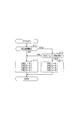
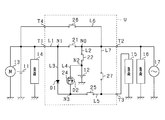
- FIG. 1 is an electric circuit diagram illustrating a power supply system according to the embodiment.
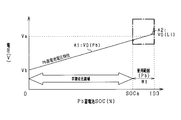
- FIG. 2A is a diagram showing an SOC usage range of a lead storage battery.
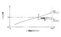
- FIG. 2B is a diagram illustrating an SOC usage range of the lithium ion storage battery.
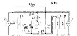
- FIG. 3A is a diagram showing a vehicle state and a state of each switch in the battery unit.
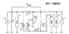
- FIG. 3B is a diagram illustrating a vehicle state and a state of each switch in the battery unit.
- FIG. 3C is a diagram illustrating a vehicle state and a state of each switch in the battery unit.
- FIG. 4A is a diagram illustrating a vehicle state and a state of each switch in the battery unit.
- FIG. 4B is a diagram illustrating a vehicle state and a state of each switch in the battery unit.
- FIG. 4C is a diagram illustrating a vehicle state and a state of each switch in the battery unit.
- FIG. 5 is a flowchart showing a processing procedure for switch switching control.
- FIG. 6 is an electric circuit diagram showing a power supply system according to a modification.
- FIG. 7 is an electric circuit diagram showing a power supply system according to a modification.
- FIG. 8 is an electric circuit diagram showing a power supply system according to a modification.
- FIG. 9 is an electric circuit diagram showing a power supply system according to a modification.
- a vehicle on which the in-vehicle power supply device of the present embodiment is mounted travels using an engine (internal combustion engine) as a drive source and has an idling stop function.
- engine internal combustion engine
- the power supply system (power supply device) according to the present embodiment is a power supply system having a lead storage battery 11 as a first power supply and a lithium ion storage battery 12 as a second power supply.
- Each storage battery 11, 12 can supply power to the starter motor 13 and various electric loads 14 to 16. Further, the storage batteries 11 and 12 can be charged by the generator 17.
- the lithium ion storage battery 12 among the storage batteries 11 and 12 is configured as a battery unit U by being accommodated in a housing (accommodating case) (not shown). The detailed configuration of the battery unit U will be described later.
- the lead storage battery 11 is a well-known general-purpose storage battery.
- the lithium ion storage battery 12 is a high-density storage battery that has less power loss in charge / discharge and higher output density and energy density than the lead storage battery 11.
- the lithium ion storage battery 12 may be a storage battery having higher energy efficiency during charging / discharging than the lead storage battery 11.
- the battery unit U is provided with a first terminal T1, a second terminal T2, and a third terminal T3 as external terminals.
- a lead storage battery 11, a starter motor 13, and an electric load 14 are connected to the first terminal T1.
- An electric load 16 and a generator 17 are connected to the second terminal T2.
- An electrical load 15 is connected to the third terminal T3.
- the electric loads 14 to 16 have different requirements for the power supply voltage supplied from the storage batteries 11 and 12.
- the electric load 15 connected to the third terminal T3 is required to have a constant supply power voltage or stable so that the supply power voltage varies within a predetermined range.
- a constant voltage demanded load is included.
- the electric loads 14 and 16 connected to the first terminal T1 and the second terminal T2 are general electric loads other than the constant voltage request load.
- the electric load 15 can also be said to be a protected load. Further, it can be said that the electric load 15 is a load that does not allow a power supply failure, and the electric load 16 is a load that allows a power supply failure.
- Specific examples of the electric load 15 that is a constant voltage required load include various electronic devices such as a navigation device, an audio device, and a meter device, and various ECUs such as an engine ECU. In this case, since the voltage fluctuation of the supplied power is suppressed, the occurrence of an unnecessary reset or the like is suppressed in each of the above devices, and a stable operation can be realized. Further, specific examples of the electric load 16 include a seat heater and a defroster heater for a rear windshield. Specific examples of the electric load 14 include wipers such as a headlight and a front windshield, a blower fan of an air conditioner, and the like.
- the electric load 15 corresponds to a “first electric load”, and the electric load 16 corresponds to a “second electric load”.
- the electrical load 15 is also referred to as a first load 15 and the electrical load 16 is also referred to as a second load 16.
- the generator 17 is an alternator (alternator) that is drivingly connected to the output shaft of the engine, and generates power using the rotation of the engine output shaft as power.
- the storage batteries 11 and 12 are charged by the power generated by the generator 17.
- the battery unit U is provided with electrical paths L1 and L2 for connecting the terminals T1 and T2 and the lithium ion storage battery 12 to each other as an in-unit electrical path.
- the battery unit U includes a first path for supplying power from the lead storage battery 11 to the second load 16 and a second path for supplying power from the lithium ion storage battery 12 to the second load 16 by the electrical paths L1 and L2.
- the 1st switch 21 is provided in the 1st path
- a second switch 22 is provided in the second path L2 that connects the connection point N0 and the lithium ion storage battery 12 on the first path L1.
- Each of the switches 21 and 22 is configured by a semiconductor switch such as a MOSFET.
- Each of the switches 21 and 22 is preferably composed of a pair of MOSFETs, and the parasitic diodes of each pair of MOSFETs are preferably connected in series so as to be opposite to each other. The parasitic diodes that are opposite to each other completely cut off the current flowing through the path in which the switches 21 and 22 are turned off when the switches 21 and 22 are turned off.
- the power supply from the lead storage battery 11 and the power supply from the lithium ion storage battery 12 can be selectively performed with respect to the second load 16.
- power supply from the lead storage battery 11 to the second load 16 can be performed by turning on the first switch 21 and turning off the second switch 22.
- the power supply from the lithium ion storage battery 12 to the second load 16 can be performed by turning off the first switch 21 and turning on the second switch 22.
- one end of the branch path L3 is connected to the branch point N1 (first branch point) between the first terminal T1 and the first switch 21.
- one end of the branch path L4 is connected to the branch point N2 (second branch point) between the lithium ion storage battery 12 and the second switch 22.
- the other ends of the branch paths L3 and L4 are connected at an intermediate point N3. That is, the branch paths L3 and L4 correspond to connection paths that connect the branch points N1 and N2. Further, the intermediate point N3 and the third terminal T3 are connected by a power feeding path L5.
- the third switch 23 is provided on the branch path L3.
- a fourth switch 24 is provided on the branch path L4.
- the third switch 23 and the fourth switch 24 each have a semiconductor switch such as a MOSFET, and diodes D1 and D2 are connected in parallel between the input and output terminals.
- the diodes D1 and D2 are connected in series with the forward direction facing each other. In other words, the diodes D1 and D2 are connected in series with the intermediate point N3 as the cathode side.
- the diode D1 corresponds to a “first diode”
- the diode D2 corresponds to a “second diode”.
- the third switch 23 corresponds to a “first semiconductor switch”
- the fourth switch 24 corresponds to a “second semiconductor switch”.
- Each switch 23, 24 is provided with a diode D1 with the first load 15 side forward from the lead storage battery 11 side, and with a diode D2 with the first load 15 side forward from the lithium ion storage battery 12 side. Is provided. Therefore, even if each switch 23 and 24 is in an OFF state, power can be supplied from any one of the storage batteries 11 and 12 to the first load 15. Further, when any of the switches 23 and 24 is in the on state, the path resistance of the branch path on the switch side in the on state is smaller than the path resistance of the branch path on the switch side in the off state. That is, in one branch path, the path resistance depends on the ON resistance of the semiconductor switch, and in the other branch path, the path resistance depends on the resistance of the diode. In this case, the ease of discharge from each storage battery 11, 12 to the first load 15 is different due to the difference in path resistance, and the power supply from either of the storage batteries 11, 12 to the first load 15 is selected. Can be done automatically.
- a relay switch 25 as a power supply switch is provided.
- the relay switch 25 is configured by, for example, a normally open latch relay circuit, and is turned on (closed) by energization accompanying power-on (IG on) to the vehicle system. The state of the relay switch 25 is maintained until the power to the vehicle system is turned off (IG off).
- IG on energization accompanying power-on
- the state of the relay switch 25 is maintained until the power to the vehicle system is turned off (IG off).
- the first path L1 and the second path L2 are high power paths through which relatively large power flows, including the power generated by the generator 17.
- the branch paths L3 and L4 and the power supply path L5 are small power paths through which smaller power flows than the paths L1 and L2.
- the battery unit U has a control unit 30 constituting battery control means. Each of the switches 21 to 25 and the control unit 30 are housed in the casing in a state of being mounted on the same substrate.
- An ECU 40 is connected to the control unit 30 from the outside of the battery unit U. That is, the control unit 30 and the ECU 40 are connected by a communication network such as CAN and can communicate with each other, and various data stored in the control unit 30 and the ECU 40 can be shared with each other.
- the ECU 40 is an electronic control device having a function of performing idling stop control.
- the idling stop control is a well-known control function that automatically stops the engine when a predetermined automatic stop condition is satisfied, and restarts the engine when the predetermined restart condition is satisfied under the automatic stop state.
- the control unit 30 switches each of the switches 21 to 25 on and off (open / close). In this case, the control unit 30 controls on / off of the switches 21 to 25 based on the running state of the vehicle and the storage states of the storage batteries 11 and 12. Thereby, in the said structure, charging / discharging is implemented using the lead storage battery 11 and the lithium ion storage battery 12 selectively.
- the charge / discharge control based on the storage state of each of the storage batteries 11 and 12 will be briefly described.
- the control unit 30 sequentially acquires the detected values of the terminal voltage or open circuit voltage of the lead storage battery 11 and the lithium ion storage battery 12.
- control part 30 acquires sequentially the detected value of the energization current of the lead storage battery 11 and the lithium ion storage battery 12 detected by the current detection means (not shown). And the control part 30 calculates SOC (residual capacity) of the lead storage battery 11 and the lithium ion storage battery 12 based on these acquired values. Based on the calculation result, the control unit 30 controls the amount of charge and the amount of discharge to the lithium ion storage battery 12 so that the SOC is maintained within a predetermined use range.
- FIG. 2A and 2B show the correlation between the open-circuit voltage (OCV) and the storage state (SOC) of the lead storage battery 11 and the lithium ion storage battery 12.
- FIG. 2A shows the correlation between the open-circuit voltage of the lead storage battery 11 and the storage state, and the SOC usage range of the lead storage battery 11 is W1.
- FIG. 2B shows a correlation between the open-circuit voltage of the lithium ion storage battery 12 and the storage state, and the SOC usage range of the lithium ion storage battery 12 is W2.
- FIG. 2B is also an enlarged view of a range corresponding to an alternate long and short dash line portion (portion indicating the SOC usage range W1 (Pb)) in FIG. 2A.
- the position of the SOC of the lithium ion storage battery 12 shown on the horizontal axis in FIG. 2 is 0%
- the SOC usage range W1 (Pb) of the lead storage battery 11 shown in FIG. 2A is the position of SOCa. It corresponds.
- the voltages Va and Vb have the same voltage value.
- the horizontal axis in FIG. 2A indicates the SOC of the lead storage battery 11, and the solid line A1 in the figure is a voltage characteristic line indicating the relationship between the SOC of the lead storage battery 11 and the open circuit voltage V0 (Pb).
- the open circuit voltage V0 (Pb) also increases in proportion to the increase in the charge amount and the increase in SOC.
- the horizontal axis in FIG. 2B shows the SOC of the lithium ion storage battery 12, and the solid line A2 in the figure is a voltage characteristic line showing the relationship between the SOC of the lithium ion storage battery 12 and the open circuit voltage V0 (Li).
- the open circuit voltage V0 (Li) increases as the amount of charge increases and the SOC increases.
- the lead storage battery 11 and the lithium ion storage battery 12 have different open-circuit voltage correlations with respect to the SOC.
- the open voltage of the lithium ion storage battery 12 is determined to be higher than the open voltage of the lead storage battery 11.
- Storage batteries 11 and 12 are concerned about early deterioration when they are overcharged or overdischarged. Therefore, the amount of charge / discharge of each storage battery 11, 12 is regulated so that the SOC of each storage battery 11, 12 falls within a range (SOC usage range) between a lower limit value and an upper limit value of a predetermined SOC that does not cause overcharge / discharge.
- the control unit 30 controls the SOC of the lead storage battery 11 within the SOC usage range W1 and the SOC of the lithium ion storage battery 12 within the SOC usage range W2. Specifically, the control unit 30 performs overcharge protection by limiting the amount of charge to each storage battery 11, 12, and further limits the amount of discharge from each storage battery 11, 12 to provide overdischarge protection. Implement the protection control to be performed.
- the battery unit U is provided with bypass paths L6 and L7 that allow the lead storage battery 11 to be connected to the electric loads 15 and 16 without using the switches 21 to 25.
- the battery unit U is provided with a fourth terminal T4, and the lead storage battery 11 is connected to the fourth terminal T4.
- the battery unit U is provided with a bypass path L6 that connects the fourth terminal T4 and the connection point N0 on the first path L1, and has a bypass path L7 that connects the connection point N0 and the third terminal T3. It has been.
- a first bypass switch 26 is provided on the bypass path L6, and a second bypass switch 27 is provided on the bypass path L7.
- the bypass switches 26 and 27 are, for example, normally closed relay switches, and are turned off (opened) by energization accompanying power-on (IG on) to the vehicle system.
- the lead storage battery 11 and the second load 16 are electrically connected even if the first switch 21 is off. Further, when both bypass switches 26 and 27 are in the on state, the lead storage battery 11 and the first load 15 are electrically connected even if the relay switch 25 is off.
- FIG. 3A shows the regenerative state.
- FIG. 3B shows a state in which the vehicle is in a normal traveling state and an engine automatic stop state by idling stop control.
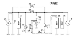
- FIG. 3C shows a state in which the vehicle is in an engine restart state.
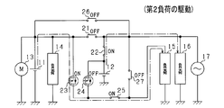
- FIG. 4A shows a state in which the second load 16 is driven.
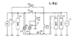
- FIG. 4B shows the lithium ion storage battery 12 in a use stop state.
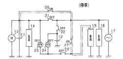
- FIG. 4C shows the time when the vehicle is stopped.
- the vehicle system is in the power-on state (IG on state), and the bypass switches 26 and 27 are off.
- each of the above states is appropriately switched.
- the switches 21 and 22 are performed.
- ON / OFF inversion and ON / OFF inversion of the switches 23 and 24 are performed.
- the first load 15 that is a constant voltage required load needs to be stably supplied continuously without interruption of the supplied power.
- diodes D1 and D2 are provided with their forward directions facing each other. Therefore, it is possible to supply power to the first load 15 via the diodes D1 and D2. Therefore, even if both of the switches 23 and 24 are temporarily turned off during the reversal switching of the switches 21 to 24, the power supply to the first load 15 is continued. Thereby, for example, in order to avoid that both the switches 23 and 24 are turned off, it is not necessary to provide a period during which both the switches 23 and 24 are turned on. As a result, a delay with respect to the drive request of the second load 16 can be suppressed.
- the control unit 30 determines whether or not the second load 16 is currently being driven (step S11). Moreover, the control part 30 determines whether SOC of the lithium ion storage battery 12 is in SOC use range W2 (step S12). In other words, the control unit 30 determines whether or not the open voltage of the lithium ion storage battery 12 is higher than the open voltage of the lead storage battery 11. And the control part 30 transfers to the process of step S13, when the determination result is NO in either determination process of step S11, S12. As a result, the control unit 30 controls the first switch 21 to be on, the second switch 22 to be off, the third switch 23 to be off, and the fourth switch 24 to be on (step S13). In this way, in the control unit 30, as shown in FIG.
- the first switch 21 is on, the second switch 22 is off, and no power is supplied from the lithium ion storage battery 12 to the second load 16.
- the third switch 23 is turned off and the fourth switch 24 is turned on. Thereby, electric power is supplied from the lithium ion storage battery 12 to the first load 15.
- step S14 the control unit 30 controls the first switch 21 to be turned off, the second switch 22 to be turned on, the third switch 23 to be turned on, and the fourth switch 24 to be turned off (step S14).
- the control unit 30 controls the first switch 21 to be turned off, the second switch 22 to be turned on, the third switch 23 to be turned on, and the fourth switch 24 to be turned off (step S14).
- the second load 16 (the electric power in the high power path) is supplied from the lithium ion storage battery 12 on the condition that there is a drive request for the second load 16 and the SOC of the lithium ion storage battery 12 is within the SOC usage range W2. Power is supplied to the load. Specifically, in the control unit 30, when both the determination results in steps S11 and S12 are YES, a switch switching process in step S14 is performed. Thereby, electric power is supplied from the lithium ion storage battery 12 to the second load 16. On the other hand, when there is a drive request for the second load 16 and the SOC of the lithium ion storage battery 12 is not within the SOC use range W2, power supply from the lead storage battery 11 to the second load 16 is performed. Specifically, in the control unit 30, when the determination result in step S11 is YES and the determination result in step S12 is NO, the switch switching process in step S13 is performed. Thereby, electric power is supplied from the lead storage battery 11 to the second load 16.
- the power system (power supply device) according to the present embodiment has the following excellent effects.
- the diodes D1 and D2 face each other forward in the branch paths L3 and L4 that supply power from the storage batteries 11 and 12 to the first load 15 (constant voltage request load).
- the diode D ⁇ b> 2 is configured to be connected in parallel between the input / output terminals of the fourth switch 24. Therefore, for the first load 15, it is possible to supply power from the lead storage battery 11 via a path passing through the diode D1 and to supply power from the lithium ion storage battery 12 via a path passing through the diode D2. Become.
- the diode D2 is provided in parallel between the input and output terminals of the fourth switch 24, the power supply is continuously performed even when the storage battery of the power supply source for the first load 15 is switched. it can. Furthermore, in this power supply system, it is possible to selectively implement power supply via a diode and power supply via a semiconductor switch. That is, in this power supply system, the power supply from the lead storage battery 11 and the lithium ion storage battery 12 are based on the state of each of the storage batteries 11 and 12 and which storage battery is the storage battery of the power supply source to the second load 16. The power supply can be selectively performed.
- the first load 15 is a constant voltage request load, and power can be supplied to the first load 15 in a stable state. Further, in this power supply system, power loss can be reduced by supplying power via an on-state semiconductor switch as compared to supplying power via a diode. As described above, in the power supply system according to the present embodiment, it is possible to appropriately supply power from the storage batteries 11 and 12 to the electric loads 15 and 16.
- the control unit 30 controls on / off of the switches 23 and 24 based on the discharge priority of the storage batteries 11 and 12 when supplying power to the first load 15. It was. Thereby, in this power supply system, it discharges with respect to the 1st load 15, giving priority to either of each storage battery 11 and 12.
- the control unit 30 included in the power supply system turns on and off the switches 21 to 24 so that the storage battery of the power supply source for the first load 15 and the storage battery of the power supply source for the second load 16 are different. It was set as the structure controlled. In other words, the control unit 30 can cause the first load 15 to discharge with priority given to one of the plurality of storage batteries in consideration of the state of power supply to the second load 16. Thereby, in this power supply system, even if the voltage of the storage battery of the power supply source fluctuates due to the power supply to the second load 16, the first load 15 (constant voltage request load) is not affected by the voltage fluctuation. ) Can be supplied. Further, when each switch is switched as described above, power can be continuously supplied to the first load 15 by the diodes D1 and D2.
- the control unit 30 is configured to control the on / off of each of the switches 21 to 24 based on the difference (high / low) of the open circuit voltage in each of the storage batteries 11 and 12.
- the control unit 30 can be judged suitably from which storage battery electric power should be supplied with respect to the 1st load 15, considering the difference in the electrical storage state of each storage battery 11 and 12.
- FIG. 1 when the power supply source to each electric load 15, 16 is switched because the open / close voltage of each storage battery 11, 12 is reversed, the diode D 1, D 2 causes the first load 15 to be changed. Power can be supplied continuously.
- diodes D1 and D2 are provided in the branch paths L3 and L4.
- the relay switch 25 is provided in the electric power feeding path
- power is supplied to the second load 16 via the large power paths (L1, L2), and the small power path (L3 to L3) is supplied to the first load 15.
- Power is supplied via L5).
- the first load 15 has a greater concern about voltage fluctuation of the supplied power.
- this power supply system by adopting a configuration including the switches 23 and 24 and the diodes D1 and D2, it is possible to avoid the concern about voltage fluctuations in the first load 15.
- the power supply system may be configured as shown in FIG.
- the semiconductor switch of the branch path L3 is omitted, and the diode D1 is provided in the branch path L3. That is, in the power supply system of this modification, only the diode D2 on the side of the lithium ion storage battery 12 with respect to the intermediate point N3 among the diodes D1 and D2 is connected in parallel between the input / output terminals of the fourth switch 24. Is provided.
- the path resistance of the branch path L4 (diode D2 side) can be made smaller than the path resistance of the branch path L3 (diode D1 side).
- the lithium ion storage battery 12 having higher energy efficiency than the lead storage battery 11 can be preferentially used to supply power to the first load 15.
- the diode D1 and the diode D2 only one of the semiconductor switches is connected in parallel, which is advantageous in simplifying the configuration.
- the power supply system may be configured as shown in FIG.
- the semiconductor switch of the branch path L3 is omitted, and the diode D1 is provided in the branch path L3.
- the branch path L4 has diodes D3 and D4 connected in parallel between the input and output terminals, and the diodes D3 and D4 are connected in series with their directions being opposite to each other.
- a pair of semiconductor switches 51 and 52 are provided. That is, in the power supply system of this modification, a series connection body of a pair of semiconductor switches 51 and 52 is provided on the branch path L4.
- diodes D3 and D4 are provided in parallel between the input and output terminals, and the diodes D3 and D4 are provided with their forward directions opposite to each other.
- the diode D3 of the semiconductor switch 51 corresponds to a “second diode”.
- the relay switch 25 of the power feeding path L5 is omitted.
- the path resistance of the branch path L4 on the lithium ion storage battery 12 side can be made smaller than that of the branch path L3 on the lead storage battery 11 side by turning on the pair of semiconductor switches 51 and 52.
- the lithium ion storage battery 12 having higher energy efficiency than the lead storage battery 11 can be preferentially used to supply power to the first load 15.
- the pair of semiconductor switches 51 and 52 are back-to-back connections in which the anodes of the diodes D3 and D4 are connected to each other, but are not limited thereto.
- the pair of semiconductor switches 51 and 52 may be configured such that the cathodes of the diodes D3 and D4 are connected to each other.
- a configuration in which a series connection body of a pair of semiconductor switches 51 and 52 provided in the branch path L4 is provided in the branch path L3 may be employed.
- the pair of semiconductor switches provided in the branch path L3 is preferably provided with diodes in parallel between the input / output terminals and with the forward directions reversed from each other.
- the power supply system may be configured as shown in FIGS. 8 and 9, only the configuration in the branch path L3 is different from that in FIG.
- a plurality of diodes D11 and D12 are provided in series in the same direction on the branch path L3. That is, in the power supply system of this modification, the diodes D11 and D12 are provided in a direction facing the diode D3 of the branch path L4, which corresponds to the “first diode”. In this case, energization is performed through the diodes D11 and D12 in the branch path L3. Therefore, in the above configuration, the voltage drop is larger than when a single diode (one diode) is provided, and discharge from the lithium ion storage battery 12 can be preferentially performed.
- a plurality (two in the figure) of semiconductor switches 23a and 23b including diodes D11 and D12 of the same direction are provided in series on the branch path L3.
- the semiconductor switches 23a and 23b correspond to “first semiconductor switches”.
- the control unit 30 can individually control the semiconductor switches 23a and 23b to turn on both of the semiconductor switches 23a and 23b, and to turn on one of the semiconductor switches 23a and 23b. To do.
- the voltage drop amount in the branch path L3 can be changed by the on / off pattern of the semiconductor switches 23a and 23b, and the discharge of the lithium ion storage battery 12 can be adjusted more finely.
- a diode switch in a direction facing the diode D3 (or the diode D2 in FIG. 1) on the branch path L4 side in the branch path L3, and a semiconductor switch including a diode in the same direction as the diode D3 The structure provided in series may be sufficient.
- a plurality of diodes (corresponding to the first diode) are provided in series in the same direction on the branch path L3, and at least one of them is preferably connected in parallel between the input / output terminals of the semiconductor switch.
- the control unit 30 may be configured to perform the following switch switching control. Specifically, when the open voltage of the lithium ion storage battery 12 is high among the storage batteries 11 and 12, the control unit 30 turns on the first switch 21, turns off the second switch 22, turns off the third switch 23, The fourth switch 24 is controlled to be turned on (the same control as in the state of FIG. 3B is performed). When the open voltage of the lead storage battery 11 is high among the storage batteries 11 and 12, the control unit 30 turns off the first switch 21, turns on the second switch 22, turns on the third switch 23, and turns on the fourth switch 24. Is turned off (the same control as in the state of FIG. 4A is performed). In this case, in the above-described configuration, the storage battery 11 or 12 can be discharged to the first load 15 with priority given to the storage battery having a high open circuit voltage.
- the second load 16 may include a driving device that outputs assist power for assisting vehicle travel.
- the rotation shaft of the drive device is drivingly connected to the engine output shaft, and the engine output shaft rotates by the rotation of the rotation shaft of the drive device.
- the driving device for example, an ISG (Integrated Starter Generator) having a power generation function and a power output function can be used.
- the combination of the first load 15 and the second load 16 may be other than the combination shown in the above embodiment.
- the first load 15 may be an electric load that does not include a constant voltage request load.
- the technology of the present disclosure is not limited to the embodiment realized by including the battery unit U. That is, the technology of the present disclosure is not limited to the configuration shown in the above embodiment.
- the power supply system of the present disclosure may be realized by a configuration other than the configuration in which the lithium ion storage battery 12 and the switches 21 to 25 are integrated and provided as one unit.
- the power supply system includes the lead storage battery 11 as the first storage battery and the lithium ion storage battery 12 as the second storage battery, but is not limited thereto.
- the second storage battery another secondary battery such as a nickel hydride storage battery may be used.
- a 1st storage battery and a 2nd storage battery can also use both storage batteries as a lead storage battery or a lithium ion storage battery.
- SYMBOLS 11 Lead storage battery (1st storage battery), 12 ... Lithium ion storage battery (2nd storage battery), 15, 16 ... Electric load, 21 ... 1st switch, 22 ... 2nd switch, 23 ... 3rd switch, 24 ... 4th Switch, D1, D2 ... Diode, U ... Battery unit.
Landscapes
- Engineering & Computer Science (AREA)
- Mechanical Engineering (AREA)
- Power Engineering (AREA)
- Charge And Discharge Circuits For Batteries Or The Like (AREA)
- Control Of Charge By Means Of Generators (AREA)
Applications Claiming Priority (2)
| Application Number | Priority Date | Filing Date | Title |
|---|---|---|---|
| JP2015-178792 | 2015-09-10 | ||
| JP2015178792A JP6468138B2 (ja) | 2015-09-10 | 2015-09-10 | 電源装置 |
Publications (1)
| Publication Number | Publication Date |
|---|---|
| WO2017043641A1 true WO2017043641A1 (ja) | 2017-03-16 |
Family
ID=58239987
Family Applications (1)
| Application Number | Title | Priority Date | Filing Date |
|---|---|---|---|
| PCT/JP2016/076661 Ceased WO2017043641A1 (ja) | 2015-09-10 | 2016-09-09 | 電源装置 |
Country Status (2)
| Country | Link |
|---|---|
| JP (1) | JP6468138B2 (enExample) |
| WO (1) | WO2017043641A1 (enExample) |
Cited By (3)
| Publication number | Priority date | Publication date | Assignee | Title |
|---|---|---|---|---|
| US20190036374A1 (en) * | 2016-03-16 | 2019-01-31 | Autonetworks Technologies, Ltd. | Vehicle power supply system and vehicle drive system |
| CN111193299A (zh) * | 2018-11-15 | 2020-05-22 | 丰田自动车株式会社 | 充电装置 |
| JP2021535874A (ja) * | 2018-09-18 | 2021-12-23 | クノル−ブレムゼ ジステーメ フューア ヌッツファールツォイゲ ゲゼルシャフト ミット ベシュレンクテル ハフツングKnorr−Bremse Systeme fuer Nutzfahrzeuge GmbH | 冗長電力を供給するためのシステムおよび方法 |
Families Citing this family (3)
| Publication number | Priority date | Publication date | Assignee | Title |
|---|---|---|---|---|
| JP6904051B2 (ja) * | 2017-05-17 | 2021-07-14 | 株式会社オートネットワーク技術研究所 | 車両用電源装置 |
| JP7013745B2 (ja) * | 2017-09-12 | 2022-02-15 | 株式会社デンソー | 電池パック |
| JP7098911B2 (ja) * | 2017-11-06 | 2022-07-12 | 株式会社デンソー | 電源システム |
Citations (3)
| Publication number | Priority date | Publication date | Assignee | Title |
|---|---|---|---|---|
| US20110012424A1 (en) * | 2007-12-21 | 2011-01-20 | Lisa Draexlmaier Gmbh | Circuit for voltage stabilization in an onboard power supply |
| JP2015076959A (ja) * | 2013-10-08 | 2015-04-20 | 株式会社オートネットワーク技術研究所 | 電源システム |
| JP2015154618A (ja) * | 2014-02-14 | 2015-08-24 | 株式会社デンソー | 電池ユニット |
Family Cites Families (3)
| Publication number | Priority date | Publication date | Assignee | Title |
|---|---|---|---|---|
| JP5488046B2 (ja) * | 2010-02-25 | 2014-05-14 | 株式会社デンソー | 車載電源装置 |
| JP5488169B2 (ja) * | 2010-04-27 | 2014-05-14 | 株式会社デンソー | 電源装置 |
| DE102014201348A1 (de) * | 2014-01-27 | 2015-07-30 | Robert Bosch Gmbh | Verfahren zum Betrieb eines Bordnetzes |
-
2015
- 2015-09-10 JP JP2015178792A patent/JP6468138B2/ja active Active
-
2016
- 2016-09-09 WO PCT/JP2016/076661 patent/WO2017043641A1/ja not_active Ceased
Patent Citations (3)
| Publication number | Priority date | Publication date | Assignee | Title |
|---|---|---|---|---|
| US20110012424A1 (en) * | 2007-12-21 | 2011-01-20 | Lisa Draexlmaier Gmbh | Circuit for voltage stabilization in an onboard power supply |
| JP2015076959A (ja) * | 2013-10-08 | 2015-04-20 | 株式会社オートネットワーク技術研究所 | 電源システム |
| JP2015154618A (ja) * | 2014-02-14 | 2015-08-24 | 株式会社デンソー | 電池ユニット |
Cited By (7)
| Publication number | Priority date | Publication date | Assignee | Title |
|---|---|---|---|---|
| US20190036374A1 (en) * | 2016-03-16 | 2019-01-31 | Autonetworks Technologies, Ltd. | Vehicle power supply system and vehicle drive system |
| US10916962B2 (en) * | 2016-03-16 | 2021-02-09 | Autonetworks Technologies, Ltd. | Dual energy store and dual charging source vehicle power supply system and vehicle drive system |
| JP2021535874A (ja) * | 2018-09-18 | 2021-12-23 | クノル−ブレムゼ ジステーメ フューア ヌッツファールツォイゲ ゲゼルシャフト ミット ベシュレンクテル ハフツングKnorr−Bremse Systeme fuer Nutzfahrzeuge GmbH | 冗長電力を供給するためのシステムおよび方法 |
| JP7293364B2 (ja) | 2018-09-18 | 2023-06-19 | クノル-ブレムゼ ジステーメ フューア ヌッツファールツォイゲ ゲゼルシャフト ミット ベシュレンクテル ハフツング | 冗長電力を供給するためのシステムおよび方法 |
| US11804727B2 (en) | 2018-09-18 | 2023-10-31 | Knorr-Bremse Systeme Fuer Nutzfahrzeuge Gmbh | System and method for providing redundant electric power |
| CN111193299A (zh) * | 2018-11-15 | 2020-05-22 | 丰田自动车株式会社 | 充电装置 |
| CN111193299B (zh) * | 2018-11-15 | 2023-09-05 | 丰田自动车株式会社 | 充电装置 |
Also Published As
| Publication number | Publication date |
|---|---|
| JP6468138B2 (ja) | 2019-02-13 |
| JP2017052446A (ja) | 2017-03-16 |
Similar Documents
| Publication | Publication Date | Title |
|---|---|---|
| JP6380171B2 (ja) | 電源システム | |
| JP6665757B2 (ja) | 電源制御装置、及び電池ユニット | |
| JP6221796B2 (ja) | 電池ユニット及び電源システム | |
| JP6468138B2 (ja) | 電源装置 | |
| JP6090195B2 (ja) | 電池ユニット | |
| JP2014030281A (ja) | 電源システム | |
| JP2016203969A (ja) | 電源装置 | |
| CN110192320B (zh) | 电源装置和电源系统 | |
| JP2015204699A (ja) | 電池ユニット | |
| JP6406328B2 (ja) | 電源装置及び電池ユニット | |
| JP2014033571A (ja) | 電源システム | |
| JP2016187235A (ja) | バッテリシステム制御装置 | |
| WO2018061681A1 (ja) | 電源システム、及び電池ユニット | |
| CN110832729B (zh) | 电源控制装置和电池单元 | |
| JP2016203792A (ja) | 電源装置 | |
| JP6724675B2 (ja) | スイッチ制御装置、電源ユニット及び電源システム | |
| WO2019151113A1 (ja) | 電源システム | |
| JP6673179B2 (ja) | 電池ユニット、及び電源システム | |
| JP2018139462A (ja) | 電源装置 | |
| JP6406205B2 (ja) | 電源装置 | |
| WO2018074545A1 (ja) | 電源装置 | |
| WO2017065161A1 (ja) | 電源装置及び電池ユニット | |
| JP7073619B2 (ja) | 電源制御装置、電池ユニット及び電源システム | |
| JP6260728B2 (ja) | 電池ユニット | |
| WO2018131367A1 (ja) | 電源装置及び電源システム |
Legal Events
| Date | Code | Title | Description |
|---|---|---|---|
| 121 | Ep: the epo has been informed by wipo that ep was designated in this application |
Ref document number: 16844502 Country of ref document: EP Kind code of ref document: A1 |
|
| NENP | Non-entry into the national phase |
Ref country code: DE |
|
| 122 | Ep: pct application non-entry in european phase |
Ref document number: 16844502 Country of ref document: EP Kind code of ref document: A1 |