WO2017043641A1 - 電源装置 - Google Patents
電源装置 Download PDFInfo
- Publication number
- WO2017043641A1 WO2017043641A1 PCT/JP2016/076661 JP2016076661W WO2017043641A1 WO 2017043641 A1 WO2017043641 A1 WO 2017043641A1 JP 2016076661 W JP2016076661 W JP 2016076661W WO 2017043641 A1 WO2017043641 A1 WO 2017043641A1
- Authority
- WO
- WIPO (PCT)
- Prior art keywords
- storage battery
- switch
- power supply
- power
- diode
- Prior art date
- Legal status (The legal status is an assumption and is not a legal conclusion. Google has not performed a legal analysis and makes no representation as to the accuracy of the status listed.)
- Ceased
Links
Images



Classifications
-
- B—PERFORMING OPERATIONS; TRANSPORTING
- B60—VEHICLES IN GENERAL
- B60R—VEHICLES, VEHICLE FITTINGS, OR VEHICLE PARTS, NOT OTHERWISE PROVIDED FOR
- B60R16/00—Electric or fluid circuits specially adapted for vehicles and not otherwise provided for; Arrangement of elements of electric or fluid circuits specially adapted for vehicles and not otherwise provided for
- B60R16/02—Electric or fluid circuits specially adapted for vehicles and not otherwise provided for; Arrangement of elements of electric or fluid circuits specially adapted for vehicles and not otherwise provided for electric constitutive elements
- B60R16/03—Electric or fluid circuits specially adapted for vehicles and not otherwise provided for; Arrangement of elements of electric or fluid circuits specially adapted for vehicles and not otherwise provided for electric constitutive elements for supply of electrical power to vehicle subsystems or for
-
- B—PERFORMING OPERATIONS; TRANSPORTING
- B60—VEHICLES IN GENERAL
- B60R—VEHICLES, VEHICLE FITTINGS, OR VEHICLE PARTS, NOT OTHERWISE PROVIDED FOR
- B60R16/00—Electric or fluid circuits specially adapted for vehicles and not otherwise provided for; Arrangement of elements of electric or fluid circuits specially adapted for vehicles and not otherwise provided for
- B60R16/02—Electric or fluid circuits specially adapted for vehicles and not otherwise provided for; Arrangement of elements of electric or fluid circuits specially adapted for vehicles and not otherwise provided for electric constitutive elements
- B60R16/03—Electric or fluid circuits specially adapted for vehicles and not otherwise provided for; Arrangement of elements of electric or fluid circuits specially adapted for vehicles and not otherwise provided for electric constitutive elements for supply of electrical power to vehicle subsystems or for
- B60R16/033—Electric or fluid circuits specially adapted for vehicles and not otherwise provided for; Arrangement of elements of electric or fluid circuits specially adapted for vehicles and not otherwise provided for electric constitutive elements for supply of electrical power to vehicle subsystems or for characterised by the use of electrical cells or batteries
-
- H—ELECTRICITY
- H02—GENERATION; CONVERSION OR DISTRIBUTION OF ELECTRIC POWER
- H02J—ELECTRIC POWER NETWORKS; CIRCUIT ARRANGEMENTS OR SYSTEMS FOR SUPPLYING OR DISTRIBUTING ELECTRIC POWER; SYSTEMS FOR STORING ELECTRIC ENERGY
- H02J7/00—Circuit arrangements for charging or discharging batteries or for supplying loads from batteries
-
- Y—GENERAL TAGGING OF NEW TECHNOLOGICAL DEVELOPMENTS; GENERAL TAGGING OF CROSS-SECTIONAL TECHNOLOGIES SPANNING OVER SEVERAL SECTIONS OF THE IPC; TECHNICAL SUBJECTS COVERED BY FORMER USPC CROSS-REFERENCE ART COLLECTIONS [XRACs] AND DIGESTS
- Y02—TECHNOLOGIES OR APPLICATIONS FOR MITIGATION OR ADAPTATION AGAINST CLIMATE CHANGE
- Y02T—CLIMATE CHANGE MITIGATION TECHNOLOGIES RELATED TO TRANSPORTATION
- Y02T10/00—Road transport of goods or passengers
- Y02T10/60—Other road transportation technologies with climate change mitigation effect
- Y02T10/70—Energy storage systems for electromobility, e.g. batteries
Definitions
- This disclosure relates to a power supply device mounted on a vehicle or the like.
- a configuration is known in which a plurality of storage batteries (lead storage battery, lithium ion storage battery, etc.) are used and electric power is supplied to various in-vehicle electric loads while using each storage battery properly.
- a switch is provided in each power supply path from the generator to each storage battery, and any one of the plurality of switches is turned on based on the storage rate of each storage battery. Charge the storage battery.
- a first load and a second load are connected in parallel to each storage battery, and power can be supplied from each storage battery to the first load and the second load.
- power is supplied from the first storage battery and the second storage battery to the first load via each switch.
- power is supplied from the first storage battery to the second load via a diode, and from the second storage battery to the second load, via a switch (protection switch) and another diode, It is configured to supply power.
- the present disclosure is intended to provide a power supply device capable of appropriately supplying power from each storage battery to an electric load.
- a power supply device having a first configuration which is an example of a technical aspect of the present disclosure, A first storage battery (11) and a second storage battery (12) are provided, and at least one of the first storage battery and the second storage battery with respect to the first electrical load (15) and the second electrical load (16).
- a first switch (21) provided in a first path (L1) for supplying power from the first storage battery to the second electrical load;
- a connection path (L3, L4) connecting the first branch point (N1) between the first storage battery and the first switch and the second branch point (N2) between the second storage battery and the second switch.
- the first diode (D1) and the second diode (D2) connected in series with the forward direction facing each other; With At least one of the first diode and the second diode is provided in parallel between the input / output terminals of the semiconductor switch (23, 24) in the connection path, A power supply path (L5) for supplying power to the first electric load is connected to an intermediate point (N3) between the cathodes of the first diode and the second diode.
- the power supply from the first storage battery and the power supply from the second storage battery can be selectively performed with respect to the second electric load.
- the first diode and the second diode are connected in series with the forward direction facing each other in the connection path for supplying power from each storage battery to the first electric load. Further, at least one of the first diode and the second diode is connected in parallel between the input / output terminals of the semiconductor switch. Therefore, for the first electrical load, it is possible to supply power from the first storage battery via a path passing through the first diode and to supply power from the second storage battery via a path passing through the second diode. It becomes. In this case, in particular, since at least one of the first diode and the second diode is provided in parallel between the input and output terminals of the semiconductor switch, the power supply is continued even when the storage battery of the power supply source for the first electric load is switched.
- the power supply device having the first configuration can appropriately supply power from each storage battery to the electric load.
- the first electric load is required to have a constant supply power voltage or stable so that the supply power voltage fluctuates at least within a predetermined range. It is a load.
- the first configuration it is possible to supply power to the first electric load in a stable state, and the requirement for constant voltage driving of the first electric load is suitably satisfied.
- control part (30) which controls ON / OFF of the said semiconductor switch based on the priority of the discharge in a said 1st storage battery and a said 2nd storage battery at the time of the electric power supply to a said 1st electric load is provided.
- the path resistance value of the connection path differs between the on state and the off state of the semiconductor switch. That is, in the OFF state of the semiconductor switch, the path resistance value is increased by the resistance of the diode.
- the first electrical load is discharged with priority given to one of the first storage battery and the second storage battery by giving a difference to the path resistance value by the on / off control of the semiconductor switch.
- the first diode is provided in parallel between the input and output terminals of the first semiconductor switch (23) on the first storage battery side with respect to the intermediate point, and the second diode. Is connected in parallel between the input and output terminals of the second semiconductor switch (24) on the second storage battery side with respect to the intermediate point, and the control unit has the first switch on, When the second switch is off, the first semiconductor switch is turned off and the second semiconductor switch is turned on. When the first switch is off and the second switch is on, the first semiconductor is turned on. The switch is turned on and the second semiconductor switch is turned off.
- the on / off of the first semiconductor switch and the second semiconductor switch is controlled in accordance with the on / off of the first switch and the second switch being alternately switched.
- the state in which power is preferentially supplied from the first storage battery to the first electric load and the state in which electric power supply is preferentially performed from the second storage battery to the first electric load are switched.
- priority is given to either the first storage battery or the second storage battery.
- the first electric load can be discharged.
- the first diode is provided in parallel with the input / output terminal of the first semiconductor switch (23) on the first storage battery side with respect to the intermediate point, and the second diode. Is connected in parallel between the input / output terminals of the second semiconductor switch (24) on the second storage battery side with respect to the intermediate point, and the first storage battery and the second storage battery are:
- the correlation of the open-circuit voltage with respect to the storage state is different, and the control unit controls on / off of the first semiconductor switch and the second semiconductor switch based on the difference of the open-circuit voltage in each storage battery.
- Each storage battery has a correlation of an open circuit voltage with respect to a storage state, and it is desirable that charge / discharge be managed according to each open circuit voltage.
- on-off of a 1st semiconductor switch and a 2nd semiconductor switch is controlled based on the difference of the open circuit voltage in each storage battery. Therefore, it is possible to appropriately determine which storage battery should supply power to the first electric load in consideration of the difference in the storage state of each storage battery.
- each diode can continuously supply power to the first electric load. .
- the second storage battery is a storage battery having higher energy efficiency during charging / discharging than the first storage battery, and the intermediate point of the first diode and the second diode is Only the second diode on the second storage battery side is provided in parallel between the input and output terminals of the semiconductor switch.
- the path resistance on the second diode side (second storage battery side) can be made smaller than that on the first diode side. Therefore, it is possible to supply power to the first electric load by preferentially using the second storage battery having higher energy efficiency than the first storage battery.
- the semiconductor switches only one of the semiconductor switches is connected in parallel, which is advantageous in simplifying the configuration.
- a power supply switch (25) is provided in the power supply path.
- the first electricity is output regardless of the on / off state of the semiconductor switch connected in parallel to these diodes. Continuous power supply to the load becomes possible.
- a power supply switch is provided in the power supply path (middle point between the first diode and the second diode to the path of the first electric load).
- connection path has diodes (D3, D4) connected in parallel between the input and output terminals on one side of the intermediate point, and the directions of the diodes are opposite to each other.
- a pair of semiconductor switches (51, 52) connected in series in an orientation state are provided, and the diodes on either side of the pair of semiconductor switches are used to connect the first diode and the second diode. Either is configured.
- a series connection body of a pair of semiconductor switches is provided on one side of the connection path with the intermediate point interposed therebetween.
- diodes are provided in parallel between the input and output terminals, and the diodes are provided with their forward directions reversed from each other.
- the semiconductor switch a pair of semiconductor switches.
- the second storage battery is a storage battery having higher energy efficiency during charging / discharging than the first storage battery, and the second of the two sides on both sides of the intermediate point in the connection path.
- the pair of semiconductor switches are provided on the storage battery side.
- the path resistance on the second storage battery side in the connection path can be made smaller than that on the first storage battery side. Therefore, it is possible to supply power to the first electric load by preferentially using the second storage battery having higher energy efficiency than the first storage battery.
- the tenth configuration includes a generator (17) that supplies electric power for charging to the first storage battery and the second storage battery, and from the generator to the first storage battery via the first path. Charging is possible, and charging from the generator to the second storage battery is enabled via the second path, and the first path and the second path are for generating power from the generator.
- the connection path and the power supply path are small power paths having a smaller maximum allowable power than the first path and the second path.
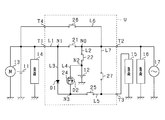
- FIG. 1 is an electric circuit diagram illustrating a power supply system according to the embodiment.
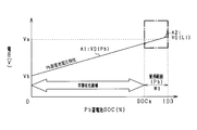
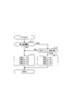
- FIG. 2A is a diagram showing an SOC usage range of a lead storage battery.
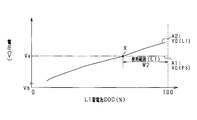
- FIG. 2B is a diagram illustrating an SOC usage range of the lithium ion storage battery.
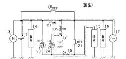
- FIG. 3A is a diagram showing a vehicle state and a state of each switch in the battery unit.
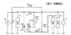
- FIG. 3B is a diagram illustrating a vehicle state and a state of each switch in the battery unit.
- FIG. 3C is a diagram illustrating a vehicle state and a state of each switch in the battery unit.
- FIG. 4A is a diagram illustrating a vehicle state and a state of each switch in the battery unit.
- FIG. 4B is a diagram illustrating a vehicle state and a state of each switch in the battery unit.
- FIG. 4C is a diagram illustrating a vehicle state and a state of each switch in the battery unit.
- FIG. 5 is a flowchart showing a processing procedure for switch switching control.
- FIG. 6 is an electric circuit diagram showing a power supply system according to a modification.
- FIG. 7 is an electric circuit diagram showing a power supply system according to a modification.
- FIG. 8 is an electric circuit diagram showing a power supply system according to a modification.
- FIG. 9 is an electric circuit diagram showing a power supply system according to a modification.
- a vehicle on which the in-vehicle power supply device of the present embodiment is mounted travels using an engine (internal combustion engine) as a drive source and has an idling stop function.
- engine internal combustion engine
- the power supply system (power supply device) according to the present embodiment is a power supply system having a lead storage battery 11 as a first power supply and a lithium ion storage battery 12 as a second power supply.
- Each storage battery 11, 12 can supply power to the starter motor 13 and various electric loads 14 to 16. Further, the storage batteries 11 and 12 can be charged by the generator 17.
- the lithium ion storage battery 12 among the storage batteries 11 and 12 is configured as a battery unit U by being accommodated in a housing (accommodating case) (not shown). The detailed configuration of the battery unit U will be described later.
- the lead storage battery 11 is a well-known general-purpose storage battery.
- the lithium ion storage battery 12 is a high-density storage battery that has less power loss in charge / discharge and higher output density and energy density than the lead storage battery 11.
- the lithium ion storage battery 12 may be a storage battery having higher energy efficiency during charging / discharging than the lead storage battery 11.
- the battery unit U is provided with a first terminal T1, a second terminal T2, and a third terminal T3 as external terminals.
- a lead storage battery 11, a starter motor 13, and an electric load 14 are connected to the first terminal T1.
- An electric load 16 and a generator 17 are connected to the second terminal T2.
- An electrical load 15 is connected to the third terminal T3.
- the electric loads 14 to 16 have different requirements for the power supply voltage supplied from the storage batteries 11 and 12.
- the electric load 15 connected to the third terminal T3 is required to have a constant supply power voltage or stable so that the supply power voltage varies within a predetermined range.
- a constant voltage demanded load is included.
- the electric loads 14 and 16 connected to the first terminal T1 and the second terminal T2 are general electric loads other than the constant voltage request load.
- the electric load 15 can also be said to be a protected load. Further, it can be said that the electric load 15 is a load that does not allow a power supply failure, and the electric load 16 is a load that allows a power supply failure.
- Specific examples of the electric load 15 that is a constant voltage required load include various electronic devices such as a navigation device, an audio device, and a meter device, and various ECUs such as an engine ECU. In this case, since the voltage fluctuation of the supplied power is suppressed, the occurrence of an unnecessary reset or the like is suppressed in each of the above devices, and a stable operation can be realized. Further, specific examples of the electric load 16 include a seat heater and a defroster heater for a rear windshield. Specific examples of the electric load 14 include wipers such as a headlight and a front windshield, a blower fan of an air conditioner, and the like.
- the electric load 15 corresponds to a “first electric load”, and the electric load 16 corresponds to a “second electric load”.
- the electrical load 15 is also referred to as a first load 15 and the electrical load 16 is also referred to as a second load 16.
- the generator 17 is an alternator (alternator) that is drivingly connected to the output shaft of the engine, and generates power using the rotation of the engine output shaft as power.
- the storage batteries 11 and 12 are charged by the power generated by the generator 17.
- the battery unit U is provided with electrical paths L1 and L2 for connecting the terminals T1 and T2 and the lithium ion storage battery 12 to each other as an in-unit electrical path.
- the battery unit U includes a first path for supplying power from the lead storage battery 11 to the second load 16 and a second path for supplying power from the lithium ion storage battery 12 to the second load 16 by the electrical paths L1 and L2.
- the 1st switch 21 is provided in the 1st path
- a second switch 22 is provided in the second path L2 that connects the connection point N0 and the lithium ion storage battery 12 on the first path L1.
- Each of the switches 21 and 22 is configured by a semiconductor switch such as a MOSFET.
- Each of the switches 21 and 22 is preferably composed of a pair of MOSFETs, and the parasitic diodes of each pair of MOSFETs are preferably connected in series so as to be opposite to each other. The parasitic diodes that are opposite to each other completely cut off the current flowing through the path in which the switches 21 and 22 are turned off when the switches 21 and 22 are turned off.
- the power supply from the lead storage battery 11 and the power supply from the lithium ion storage battery 12 can be selectively performed with respect to the second load 16.
- power supply from the lead storage battery 11 to the second load 16 can be performed by turning on the first switch 21 and turning off the second switch 22.
- the power supply from the lithium ion storage battery 12 to the second load 16 can be performed by turning off the first switch 21 and turning on the second switch 22.
- one end of the branch path L3 is connected to the branch point N1 (first branch point) between the first terminal T1 and the first switch 21.
- one end of the branch path L4 is connected to the branch point N2 (second branch point) between the lithium ion storage battery 12 and the second switch 22.
- the other ends of the branch paths L3 and L4 are connected at an intermediate point N3. That is, the branch paths L3 and L4 correspond to connection paths that connect the branch points N1 and N2. Further, the intermediate point N3 and the third terminal T3 are connected by a power feeding path L5.
- the third switch 23 is provided on the branch path L3.
- a fourth switch 24 is provided on the branch path L4.
- the third switch 23 and the fourth switch 24 each have a semiconductor switch such as a MOSFET, and diodes D1 and D2 are connected in parallel between the input and output terminals.
- the diodes D1 and D2 are connected in series with the forward direction facing each other. In other words, the diodes D1 and D2 are connected in series with the intermediate point N3 as the cathode side.
- the diode D1 corresponds to a “first diode”
- the diode D2 corresponds to a “second diode”.
- the third switch 23 corresponds to a “first semiconductor switch”
- the fourth switch 24 corresponds to a “second semiconductor switch”.
- Each switch 23, 24 is provided with a diode D1 with the first load 15 side forward from the lead storage battery 11 side, and with a diode D2 with the first load 15 side forward from the lithium ion storage battery 12 side. Is provided. Therefore, even if each switch 23 and 24 is in an OFF state, power can be supplied from any one of the storage batteries 11 and 12 to the first load 15. Further, when any of the switches 23 and 24 is in the on state, the path resistance of the branch path on the switch side in the on state is smaller than the path resistance of the branch path on the switch side in the off state. That is, in one branch path, the path resistance depends on the ON resistance of the semiconductor switch, and in the other branch path, the path resistance depends on the resistance of the diode. In this case, the ease of discharge from each storage battery 11, 12 to the first load 15 is different due to the difference in path resistance, and the power supply from either of the storage batteries 11, 12 to the first load 15 is selected. Can be done automatically.
- a relay switch 25 as a power supply switch is provided.
- the relay switch 25 is configured by, for example, a normally open latch relay circuit, and is turned on (closed) by energization accompanying power-on (IG on) to the vehicle system. The state of the relay switch 25 is maintained until the power to the vehicle system is turned off (IG off).
- IG on energization accompanying power-on
- the state of the relay switch 25 is maintained until the power to the vehicle system is turned off (IG off).
- the first path L1 and the second path L2 are high power paths through which relatively large power flows, including the power generated by the generator 17.
- the branch paths L3 and L4 and the power supply path L5 are small power paths through which smaller power flows than the paths L1 and L2.
- the battery unit U has a control unit 30 constituting battery control means. Each of the switches 21 to 25 and the control unit 30 are housed in the casing in a state of being mounted on the same substrate.
- An ECU 40 is connected to the control unit 30 from the outside of the battery unit U. That is, the control unit 30 and the ECU 40 are connected by a communication network such as CAN and can communicate with each other, and various data stored in the control unit 30 and the ECU 40 can be shared with each other.
- the ECU 40 is an electronic control device having a function of performing idling stop control.
- the idling stop control is a well-known control function that automatically stops the engine when a predetermined automatic stop condition is satisfied, and restarts the engine when the predetermined restart condition is satisfied under the automatic stop state.
- the control unit 30 switches each of the switches 21 to 25 on and off (open / close). In this case, the control unit 30 controls on / off of the switches 21 to 25 based on the running state of the vehicle and the storage states of the storage batteries 11 and 12. Thereby, in the said structure, charging / discharging is implemented using the lead storage battery 11 and the lithium ion storage battery 12 selectively.
- the charge / discharge control based on the storage state of each of the storage batteries 11 and 12 will be briefly described.
- the control unit 30 sequentially acquires the detected values of the terminal voltage or open circuit voltage of the lead storage battery 11 and the lithium ion storage battery 12.
- control part 30 acquires sequentially the detected value of the energization current of the lead storage battery 11 and the lithium ion storage battery 12 detected by the current detection means (not shown). And the control part 30 calculates SOC (residual capacity) of the lead storage battery 11 and the lithium ion storage battery 12 based on these acquired values. Based on the calculation result, the control unit 30 controls the amount of charge and the amount of discharge to the lithium ion storage battery 12 so that the SOC is maintained within a predetermined use range.
- FIG. 2A and 2B show the correlation between the open-circuit voltage (OCV) and the storage state (SOC) of the lead storage battery 11 and the lithium ion storage battery 12.
- FIG. 2A shows the correlation between the open-circuit voltage of the lead storage battery 11 and the storage state, and the SOC usage range of the lead storage battery 11 is W1.
- FIG. 2B shows a correlation between the open-circuit voltage of the lithium ion storage battery 12 and the storage state, and the SOC usage range of the lithium ion storage battery 12 is W2.
- FIG. 2B is also an enlarged view of a range corresponding to an alternate long and short dash line portion (portion indicating the SOC usage range W1 (Pb)) in FIG. 2A.
- the position of the SOC of the lithium ion storage battery 12 shown on the horizontal axis in FIG. 2 is 0%
- the SOC usage range W1 (Pb) of the lead storage battery 11 shown in FIG. 2A is the position of SOCa. It corresponds.
- the voltages Va and Vb have the same voltage value.
- the horizontal axis in FIG. 2A indicates the SOC of the lead storage battery 11, and the solid line A1 in the figure is a voltage characteristic line indicating the relationship between the SOC of the lead storage battery 11 and the open circuit voltage V0 (Pb).
- the open circuit voltage V0 (Pb) also increases in proportion to the increase in the charge amount and the increase in SOC.
- the horizontal axis in FIG. 2B shows the SOC of the lithium ion storage battery 12, and the solid line A2 in the figure is a voltage characteristic line showing the relationship between the SOC of the lithium ion storage battery 12 and the open circuit voltage V0 (Li).
- the open circuit voltage V0 (Li) increases as the amount of charge increases and the SOC increases.
- the lead storage battery 11 and the lithium ion storage battery 12 have different open-circuit voltage correlations with respect to the SOC.
- the open voltage of the lithium ion storage battery 12 is determined to be higher than the open voltage of the lead storage battery 11.
- Storage batteries 11 and 12 are concerned about early deterioration when they are overcharged or overdischarged. Therefore, the amount of charge / discharge of each storage battery 11, 12 is regulated so that the SOC of each storage battery 11, 12 falls within a range (SOC usage range) between a lower limit value and an upper limit value of a predetermined SOC that does not cause overcharge / discharge.
- the control unit 30 controls the SOC of the lead storage battery 11 within the SOC usage range W1 and the SOC of the lithium ion storage battery 12 within the SOC usage range W2. Specifically, the control unit 30 performs overcharge protection by limiting the amount of charge to each storage battery 11, 12, and further limits the amount of discharge from each storage battery 11, 12 to provide overdischarge protection. Implement the protection control to be performed.
- the battery unit U is provided with bypass paths L6 and L7 that allow the lead storage battery 11 to be connected to the electric loads 15 and 16 without using the switches 21 to 25.
- the battery unit U is provided with a fourth terminal T4, and the lead storage battery 11 is connected to the fourth terminal T4.
- the battery unit U is provided with a bypass path L6 that connects the fourth terminal T4 and the connection point N0 on the first path L1, and has a bypass path L7 that connects the connection point N0 and the third terminal T3. It has been.
- a first bypass switch 26 is provided on the bypass path L6, and a second bypass switch 27 is provided on the bypass path L7.
- the bypass switches 26 and 27 are, for example, normally closed relay switches, and are turned off (opened) by energization accompanying power-on (IG on) to the vehicle system.
- the lead storage battery 11 and the second load 16 are electrically connected even if the first switch 21 is off. Further, when both bypass switches 26 and 27 are in the on state, the lead storage battery 11 and the first load 15 are electrically connected even if the relay switch 25 is off.
- FIG. 3A shows the regenerative state.
- FIG. 3B shows a state in which the vehicle is in a normal traveling state and an engine automatic stop state by idling stop control.
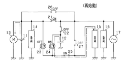
- FIG. 3C shows a state in which the vehicle is in an engine restart state.
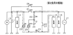
- FIG. 4A shows a state in which the second load 16 is driven.
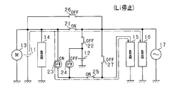
- FIG. 4B shows the lithium ion storage battery 12 in a use stop state.
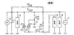
- FIG. 4C shows the time when the vehicle is stopped.
- the vehicle system is in the power-on state (IG on state), and the bypass switches 26 and 27 are off.
- each of the above states is appropriately switched.
- the switches 21 and 22 are performed.
- ON / OFF inversion and ON / OFF inversion of the switches 23 and 24 are performed.
- the first load 15 that is a constant voltage required load needs to be stably supplied continuously without interruption of the supplied power.
- diodes D1 and D2 are provided with their forward directions facing each other. Therefore, it is possible to supply power to the first load 15 via the diodes D1 and D2. Therefore, even if both of the switches 23 and 24 are temporarily turned off during the reversal switching of the switches 21 to 24, the power supply to the first load 15 is continued. Thereby, for example, in order to avoid that both the switches 23 and 24 are turned off, it is not necessary to provide a period during which both the switches 23 and 24 are turned on. As a result, a delay with respect to the drive request of the second load 16 can be suppressed.
- the control unit 30 determines whether or not the second load 16 is currently being driven (step S11). Moreover, the control part 30 determines whether SOC of the lithium ion storage battery 12 is in SOC use range W2 (step S12). In other words, the control unit 30 determines whether or not the open voltage of the lithium ion storage battery 12 is higher than the open voltage of the lead storage battery 11. And the control part 30 transfers to the process of step S13, when the determination result is NO in either determination process of step S11, S12. As a result, the control unit 30 controls the first switch 21 to be on, the second switch 22 to be off, the third switch 23 to be off, and the fourth switch 24 to be on (step S13). In this way, in the control unit 30, as shown in FIG.
- the first switch 21 is on, the second switch 22 is off, and no power is supplied from the lithium ion storage battery 12 to the second load 16.
- the third switch 23 is turned off and the fourth switch 24 is turned on. Thereby, electric power is supplied from the lithium ion storage battery 12 to the first load 15.
- step S14 the control unit 30 controls the first switch 21 to be turned off, the second switch 22 to be turned on, the third switch 23 to be turned on, and the fourth switch 24 to be turned off (step S14).
- the control unit 30 controls the first switch 21 to be turned off, the second switch 22 to be turned on, the third switch 23 to be turned on, and the fourth switch 24 to be turned off (step S14).
- the second load 16 (the electric power in the high power path) is supplied from the lithium ion storage battery 12 on the condition that there is a drive request for the second load 16 and the SOC of the lithium ion storage battery 12 is within the SOC usage range W2. Power is supplied to the load. Specifically, in the control unit 30, when both the determination results in steps S11 and S12 are YES, a switch switching process in step S14 is performed. Thereby, electric power is supplied from the lithium ion storage battery 12 to the second load 16. On the other hand, when there is a drive request for the second load 16 and the SOC of the lithium ion storage battery 12 is not within the SOC use range W2, power supply from the lead storage battery 11 to the second load 16 is performed. Specifically, in the control unit 30, when the determination result in step S11 is YES and the determination result in step S12 is NO, the switch switching process in step S13 is performed. Thereby, electric power is supplied from the lead storage battery 11 to the second load 16.
- the power system (power supply device) according to the present embodiment has the following excellent effects.
- the diodes D1 and D2 face each other forward in the branch paths L3 and L4 that supply power from the storage batteries 11 and 12 to the first load 15 (constant voltage request load).
- the diode D ⁇ b> 2 is configured to be connected in parallel between the input / output terminals of the fourth switch 24. Therefore, for the first load 15, it is possible to supply power from the lead storage battery 11 via a path passing through the diode D1 and to supply power from the lithium ion storage battery 12 via a path passing through the diode D2. Become.
- the diode D2 is provided in parallel between the input and output terminals of the fourth switch 24, the power supply is continuously performed even when the storage battery of the power supply source for the first load 15 is switched. it can. Furthermore, in this power supply system, it is possible to selectively implement power supply via a diode and power supply via a semiconductor switch. That is, in this power supply system, the power supply from the lead storage battery 11 and the lithium ion storage battery 12 are based on the state of each of the storage batteries 11 and 12 and which storage battery is the storage battery of the power supply source to the second load 16. The power supply can be selectively performed.
- the first load 15 is a constant voltage request load, and power can be supplied to the first load 15 in a stable state. Further, in this power supply system, power loss can be reduced by supplying power via an on-state semiconductor switch as compared to supplying power via a diode. As described above, in the power supply system according to the present embodiment, it is possible to appropriately supply power from the storage batteries 11 and 12 to the electric loads 15 and 16.
- the control unit 30 controls on / off of the switches 23 and 24 based on the discharge priority of the storage batteries 11 and 12 when supplying power to the first load 15. It was. Thereby, in this power supply system, it discharges with respect to the 1st load 15, giving priority to either of each storage battery 11 and 12.
- the control unit 30 included in the power supply system turns on and off the switches 21 to 24 so that the storage battery of the power supply source for the first load 15 and the storage battery of the power supply source for the second load 16 are different. It was set as the structure controlled. In other words, the control unit 30 can cause the first load 15 to discharge with priority given to one of the plurality of storage batteries in consideration of the state of power supply to the second load 16. Thereby, in this power supply system, even if the voltage of the storage battery of the power supply source fluctuates due to the power supply to the second load 16, the first load 15 (constant voltage request load) is not affected by the voltage fluctuation. ) Can be supplied. Further, when each switch is switched as described above, power can be continuously supplied to the first load 15 by the diodes D1 and D2.
- the control unit 30 is configured to control the on / off of each of the switches 21 to 24 based on the difference (high / low) of the open circuit voltage in each of the storage batteries 11 and 12.
- the control unit 30 can be judged suitably from which storage battery electric power should be supplied with respect to the 1st load 15, considering the difference in the electrical storage state of each storage battery 11 and 12.
- FIG. 1 when the power supply source to each electric load 15, 16 is switched because the open / close voltage of each storage battery 11, 12 is reversed, the diode D 1, D 2 causes the first load 15 to be changed. Power can be supplied continuously.
- diodes D1 and D2 are provided in the branch paths L3 and L4.
- the relay switch 25 is provided in the electric power feeding path
- power is supplied to the second load 16 via the large power paths (L1, L2), and the small power path (L3 to L3) is supplied to the first load 15.
- Power is supplied via L5).
- the first load 15 has a greater concern about voltage fluctuation of the supplied power.
- this power supply system by adopting a configuration including the switches 23 and 24 and the diodes D1 and D2, it is possible to avoid the concern about voltage fluctuations in the first load 15.
- the power supply system may be configured as shown in FIG.
- the semiconductor switch of the branch path L3 is omitted, and the diode D1 is provided in the branch path L3. That is, in the power supply system of this modification, only the diode D2 on the side of the lithium ion storage battery 12 with respect to the intermediate point N3 among the diodes D1 and D2 is connected in parallel between the input / output terminals of the fourth switch 24. Is provided.
- the path resistance of the branch path L4 (diode D2 side) can be made smaller than the path resistance of the branch path L3 (diode D1 side).
- the lithium ion storage battery 12 having higher energy efficiency than the lead storage battery 11 can be preferentially used to supply power to the first load 15.
- the diode D1 and the diode D2 only one of the semiconductor switches is connected in parallel, which is advantageous in simplifying the configuration.
- the power supply system may be configured as shown in FIG.
- the semiconductor switch of the branch path L3 is omitted, and the diode D1 is provided in the branch path L3.
- the branch path L4 has diodes D3 and D4 connected in parallel between the input and output terminals, and the diodes D3 and D4 are connected in series with their directions being opposite to each other.
- a pair of semiconductor switches 51 and 52 are provided. That is, in the power supply system of this modification, a series connection body of a pair of semiconductor switches 51 and 52 is provided on the branch path L4.
- diodes D3 and D4 are provided in parallel between the input and output terminals, and the diodes D3 and D4 are provided with their forward directions opposite to each other.
- the diode D3 of the semiconductor switch 51 corresponds to a “second diode”.
- the relay switch 25 of the power feeding path L5 is omitted.
- the path resistance of the branch path L4 on the lithium ion storage battery 12 side can be made smaller than that of the branch path L3 on the lead storage battery 11 side by turning on the pair of semiconductor switches 51 and 52.
- the lithium ion storage battery 12 having higher energy efficiency than the lead storage battery 11 can be preferentially used to supply power to the first load 15.
- the pair of semiconductor switches 51 and 52 are back-to-back connections in which the anodes of the diodes D3 and D4 are connected to each other, but are not limited thereto.
- the pair of semiconductor switches 51 and 52 may be configured such that the cathodes of the diodes D3 and D4 are connected to each other.
- a configuration in which a series connection body of a pair of semiconductor switches 51 and 52 provided in the branch path L4 is provided in the branch path L3 may be employed.
- the pair of semiconductor switches provided in the branch path L3 is preferably provided with diodes in parallel between the input / output terminals and with the forward directions reversed from each other.
- the power supply system may be configured as shown in FIGS. 8 and 9, only the configuration in the branch path L3 is different from that in FIG.
- a plurality of diodes D11 and D12 are provided in series in the same direction on the branch path L3. That is, in the power supply system of this modification, the diodes D11 and D12 are provided in a direction facing the diode D3 of the branch path L4, which corresponds to the “first diode”. In this case, energization is performed through the diodes D11 and D12 in the branch path L3. Therefore, in the above configuration, the voltage drop is larger than when a single diode (one diode) is provided, and discharge from the lithium ion storage battery 12 can be preferentially performed.
- a plurality (two in the figure) of semiconductor switches 23a and 23b including diodes D11 and D12 of the same direction are provided in series on the branch path L3.
- the semiconductor switches 23a and 23b correspond to “first semiconductor switches”.
- the control unit 30 can individually control the semiconductor switches 23a and 23b to turn on both of the semiconductor switches 23a and 23b, and to turn on one of the semiconductor switches 23a and 23b. To do.
- the voltage drop amount in the branch path L3 can be changed by the on / off pattern of the semiconductor switches 23a and 23b, and the discharge of the lithium ion storage battery 12 can be adjusted more finely.
- a diode switch in a direction facing the diode D3 (or the diode D2 in FIG. 1) on the branch path L4 side in the branch path L3, and a semiconductor switch including a diode in the same direction as the diode D3 The structure provided in series may be sufficient.
- a plurality of diodes (corresponding to the first diode) are provided in series in the same direction on the branch path L3, and at least one of them is preferably connected in parallel between the input / output terminals of the semiconductor switch.
- the control unit 30 may be configured to perform the following switch switching control. Specifically, when the open voltage of the lithium ion storage battery 12 is high among the storage batteries 11 and 12, the control unit 30 turns on the first switch 21, turns off the second switch 22, turns off the third switch 23, The fourth switch 24 is controlled to be turned on (the same control as in the state of FIG. 3B is performed). When the open voltage of the lead storage battery 11 is high among the storage batteries 11 and 12, the control unit 30 turns off the first switch 21, turns on the second switch 22, turns on the third switch 23, and turns on the fourth switch 24. Is turned off (the same control as in the state of FIG. 4A is performed). In this case, in the above-described configuration, the storage battery 11 or 12 can be discharged to the first load 15 with priority given to the storage battery having a high open circuit voltage.
- the second load 16 may include a driving device that outputs assist power for assisting vehicle travel.
- the rotation shaft of the drive device is drivingly connected to the engine output shaft, and the engine output shaft rotates by the rotation of the rotation shaft of the drive device.
- the driving device for example, an ISG (Integrated Starter Generator) having a power generation function and a power output function can be used.
- the combination of the first load 15 and the second load 16 may be other than the combination shown in the above embodiment.
- the first load 15 may be an electric load that does not include a constant voltage request load.
- the technology of the present disclosure is not limited to the embodiment realized by including the battery unit U. That is, the technology of the present disclosure is not limited to the configuration shown in the above embodiment.
- the power supply system of the present disclosure may be realized by a configuration other than the configuration in which the lithium ion storage battery 12 and the switches 21 to 25 are integrated and provided as one unit.
- the power supply system includes the lead storage battery 11 as the first storage battery and the lithium ion storage battery 12 as the second storage battery, but is not limited thereto.
- the second storage battery another secondary battery such as a nickel hydride storage battery may be used.
- a 1st storage battery and a 2nd storage battery can also use both storage batteries as a lead storage battery or a lithium ion storage battery.
- SYMBOLS 11 Lead storage battery (1st storage battery), 12 ... Lithium ion storage battery (2nd storage battery), 15, 16 ... Electric load, 21 ... 1st switch, 22 ... 2nd switch, 23 ... 3rd switch, 24 ... 4th Switch, D1, D2 ... Diode, U ... Battery unit.
Landscapes
- Engineering & Computer Science (AREA)
- Mechanical Engineering (AREA)
- Power Engineering (AREA)
- Charge And Discharge Circuits For Batteries Or The Like (AREA)
- Control Of Charge By Means Of Generators (AREA)
Abstract
鉛蓄電池11から負荷16に電力供給する経路L1に設けられたスイッチ21と、リチウムイオン蓄電池12から負荷16に電力供給する経路L2に設けられたスイッチ22と、鉛蓄電池11及びスイッチ21の間の分岐点N1と、リチウムイオン蓄電池12及びスイッチ22の間の分岐点N2とを接続する経路L3,L4において、順方向を向かい合わせにして直列に接続されたダイオードD1,D2と、を備えている。ダイオードD1,D2は、経路L3,L4において、各スイッチ23,24の入出力端子間に並列に接続されて設けられており、ダイオードD1,D2の各カソードの間となる中間点N3に、第1負荷15に電力供給する給電経路L5が接続される構成となっている。
Description
本開示は、車両等に搭載される電源装置に関する。
例えば車両に搭載される車載電源システムとしては、複数の蓄電池(鉛蓄電池やリチウムイオン蓄電池等)を用い、各蓄電池を使い分けながら車載の各種電気負荷に対して電力を供給する構成が知られている。例えば特許文献1に記載の技術では、発電機から各蓄電池への給電経路にスイッチをそれぞれ設け、各蓄電池の蓄電率に基づいて、複数のスイッチのいずれかをオンにし、発電機からいずれかの蓄電池に対して充電を行う。また、特許文献1に記載の技術では、各蓄電池に対して並列に第1負荷及び第2負荷を接続し、各蓄電池から第1負荷及び第2負荷に対して給電できる。この場合、第1蓄電池及び第2蓄電池から第1負荷に対しては、各スイッチを介して、電力を供給する構成としている。また、第1蓄電池から第2負荷に対しては、ダイオードを介して電力を供給し、第2蓄電池から第2負荷に対しては、スイッチ(保護スイッチ)と、別のダイオードとを介して、電力を供給する構成としている。
しかしながら、上記従来の構成では、電気負荷に対して各蓄電池から電力を供給する場合に、一対のダイオードのいずれかを介して、いずれかの蓄電池から電力供給が行われるが、どの蓄電池から電力供給が行われるかを適正に管理できない。この場合、各蓄電池においては、給電対象や蓄電状態に応じて、電気負荷に対する電力供給の状態を管理することが望ましく、かかる点において改善の余地があると考えられる。なお、特許文献1には、第2蓄電池の出力側にスイッチが設けられた構成が示されているが、このスイッチは、オフすることで第2蓄電池の電力の入出力を遮断する保護スイッチの機能を有している。よって、スイッチがオフ状態では、2つの電気負荷(第1負荷及び第2負荷)のどちらにも電力を供給できない。そのため、特許文献1に記載の技術には、第1負荷及び第2負荷に対する電力供給を適正に行う上で改善の余地があると考えられる。
本開示は、各蓄電池から電気負荷に対して適正な電力供給を実施できる電源装置を提供することを目的とする。
本開示の技術態様の一例である第1の構成の電源装置は、
第1蓄電池(11)と第2蓄電池(12)とを備え、第1電気負荷(15)と第2電気負荷(16)とに対して、前記第1蓄電池及び前記第2蓄電池の少なくとも一方から電力を供給する電源システムに適用され、
前記第1蓄電池から前記第2電気負荷に電力供給する第1経路(L1)に設けられた第1スイッチ(21)と、
前記第2蓄電池から前記第2電気負荷に電力供給する第2経路(L2)に設けられた第2スイッチ(22)と、
前記第1蓄電池及び前記第1スイッチの間の第1分岐点(N1)と、前記第2蓄電池及び前記第2スイッチの間の第2分岐点(N2)とを接続する接続経路(L3,L4)において、順方向を向かい合わせにして直列に接続された第1ダイオード(D1)及び第2ダイオード(D2)と、
を備え、
前記第1ダイオード及び前記第2ダイオードの少なくともいずれかは、前記接続経路において半導体スイッチ(23,24)の入出力端子間に並列に接続されて設けられており、
前記第1ダイオード及び前記第2ダイオードの各カソードの間となる中間点(N3)に、前記第1電気負荷に電力供給する給電経路(L5)が接続される構成となっている。
第1蓄電池(11)と第2蓄電池(12)とを備え、第1電気負荷(15)と第2電気負荷(16)とに対して、前記第1蓄電池及び前記第2蓄電池の少なくとも一方から電力を供給する電源システムに適用され、
前記第1蓄電池から前記第2電気負荷に電力供給する第1経路(L1)に設けられた第1スイッチ(21)と、
前記第2蓄電池から前記第2電気負荷に電力供給する第2経路(L2)に設けられた第2スイッチ(22)と、
前記第1蓄電池及び前記第1スイッチの間の第1分岐点(N1)と、前記第2蓄電池及び前記第2スイッチの間の第2分岐点(N2)とを接続する接続経路(L3,L4)において、順方向を向かい合わせにして直列に接続された第1ダイオード(D1)及び第2ダイオード(D2)と、
を備え、
前記第1ダイオード及び前記第2ダイオードの少なくともいずれかは、前記接続経路において半導体スイッチ(23,24)の入出力端子間に並列に接続されて設けられており、
前記第1ダイオード及び前記第2ダイオードの各カソードの間となる中間点(N3)に、前記第1電気負荷に電力供給する給電経路(L5)が接続される構成となっている。
上記第1の構成では、第2電気負荷に対して、第1蓄電池からの電力供給と第2蓄電池からの電力供給とが選択的に実施できる。この場合には、第1スイッチをオン、第2スイッチをオフにすることで、第1蓄電池から第2電気負荷への電力供給が可能となる。また、第1スイッチをオフ、第2スイッチをオンにすることで、第2蓄電池から第2電気負荷への電力供給が可能となる。
第1電気負荷に対して各蓄電池から電力供給を行う接続経路には、第1ダイオードと第2ダイオードとが、順方向を向かい合わせにして直列に接続されている。また、その第1ダイオード及び第2ダイオードの少なくともいずれかは、半導体スイッチの入出力端子間に並列に接続されている。そのため、第1電気負荷に対しては、第1ダイオードを通る経路を介しての第1蓄電池からの電力供給と、第2ダイオードを通る経路を介しての第2蓄電池からの電力供給とが可能となる。この場合、特に、第1ダイオード及び第2ダイオードの少なくともいずれかを半導体スイッチの入出力端子間に並列に設けたため、第1電気負荷に対する電力供給元の蓄電池の切り替え時にも、電力供給を継続的に実施できる。さらに、ダイオードを経由した電力供給と半導体スイッチを経由した電力供給とを選択的に実施できる。つまり、各蓄電池の状態や、第2電気負荷への電力供給元の蓄電池がどの蓄電池であるかに基づいて、第1蓄電池からの電力供給と第2蓄電池からの電力供給とを選択的に実施できる。また、オン状態の半導体スイッチを経由して電力供給する場合には、ダイオードを経由して電力供給する場合に比べて、電力損失を減らせる。以上により、第1の構成の電源装置は、各蓄電池から電気負荷に対して適正な電力供給を実施できる。
第2の構成では、前記第1電気負荷は、供給電力の電圧が一定であること、又は、前記供給電力の電圧が少なくとも所定範囲内で変動するように安定していることが要求される電気負荷である。
この場合、上記第1の構成を用いることにより、第1電気負荷に対して安定状態で電力供給を実施でき、第1電気負荷の定電圧駆動の要求が好適に満たされる。
第3の構成では、前記第1電気負荷への電力供給時に、前記第1蓄電池及び前記第2蓄電池における放電の優先度に基づいて、前記半導体スイッチのオンオフを制御する制御部(30)を備える。
半導体スイッチの入出力端子間に並列にダイオードを設けた構成では、半導体スイッチのオンオフにかかわらず、接続経路に継続的に電流を流すことが可能である。しかし、半導体スイッチのオン状態とオフ状態とでは、接続経路の経路抵抗値が相違する。つまり、半導体スイッチのオフ状態では、ダイオードの抵抗分だけ、経路抵抗値が大きくなる。この場合、半導体スイッチのオンオフ制御により経路抵抗値に差を付けることで、第1蓄電池及び第2蓄電池のうちのいずれかを優先して、第1電気負荷に対する放電を行わせる。これにより、例えば、各蓄電池の状態に応じて、電気負荷に対する蓄電池からの放電を選択的に実施できる。
第4の構成では、前記第1ダイオードは、前記中間点に対し前記第1蓄電池の側において、第1半導体スイッチ(23)の入出力端子間に並列に接続されて設けられ、前記第2ダイオードは、前記中間点に対し前記第2蓄電池の側において、第2半導体スイッチ(24)の入出力端子間に並列に接続されて設けられており、前記制御部は、前記第1スイッチがオン、前記第2スイッチがオフの場合に、前記第1半導体スイッチをオフ、前記第2半導体スイッチをオンに制御し、前記第1スイッチがオフ、前記第2スイッチがオンの場合に、前記第1半導体スイッチをオン、前記第2半導体スイッチをオフに制御する。
上記第4の構成では、第1スイッチ及び第2スイッチのオンオフが互い違いに切り替えられることに合わせて、第1半導体スイッチ及び第2半導体スイッチのオンオフが制御される。これにより、第1電気負荷に対して第1蓄電池から優先的に電力供給が行われる状態と、第1電気負荷に対して第2蓄電池から優先的に電力供給が行われる状態とが切り替えられる。例えば、第2電気負荷の駆動要求の有無に応じて、第1スイッチ及び第2スイッチのオンオフが切り替えられる場合には、それに対応させて、第1蓄電池及び第2蓄電池のうちのいずれかを優先して、第1電気負荷に対する放電を行わせることができる。この場合、第2電気負荷に対する電力供給により、その電力供給元の蓄電池の電圧が変動しても、その電圧変動の影響を受けることなく、第1電気負荷(定電圧要求負荷)への電力供給が行える。また、上記のように各スイッチが切り替えられる際には、各ダイオードにより、第1電気負荷に対して継続的に電力供給を実施できる。
第5の構成では、前記第1ダイオードは、前記中間点に対し前記第1蓄電池の側において、第1半導体スイッチ(23)の入出力端子間に並列に接続されて設けられ、前記第2ダイオードは、前記中間点に対し前記第2蓄電池の側において、第2半導体スイッチ(24)の入出力端子間に並列に接続されて設けられており、前記第1蓄電池と前記第2蓄電池とは、蓄電状態に対する開放電圧の相関が相違しており、前記制御部は、前記各蓄電池における前記開放電圧の差に基づいて、前記第1半導体スイッチ及び前記第2半導体スイッチのオンオフを制御する。
各蓄電池においては、蓄電状態に対する開放電圧の相関を有しており、それぞれの開放電圧に応じて、充放電が管理されることが望ましい。これに対し、上記第5の構成では、各蓄電池における開放電圧の差に基づいて、第1半導体スイッチ及び第2半導体スイッチのオンオフが制御される。そのため、各蓄電池の蓄電状態の違いを考慮して、どの蓄電池から第1電気負荷に対して電力供給すべきかを好適に判断できる。また、各蓄電池の開放電圧の高低が逆転する等して、各電気負荷への電力供給元が切り替えられる際には、各ダイオードにより、第1電気負荷に対して継続的に電力供給を実施できる。
第6の構成では、前記第2蓄電池は、前記第1蓄電池に比べて、充放電時のエネルギ効率が高い蓄電池であり、前記第1ダイオード及び前記第2ダイオードのうち、前記中間点に対し前記第2蓄電池の側の前記第2ダイオードのみが、前記半導体スイッチの入出力端子間に並列に接続されて設けられている。
上記第6の構成では、半導体スイッチのオンにより、第2ダイオードの側(第2蓄電池の側)の経路抵抗を、第1ダイオードの側よりも小さくできる。これにより、第1蓄電池よりもエネルギ効率の高い第2蓄電池を優先的に用いて、第1電気負荷に対する電力供給が行える。この場合、第1ダイオード及び第2ダイオードのうち、半導体スイッチが並列に接続されているのは一方のみであり、構成の簡素化を図る上で有利となる。
第7の構成では、前記給電経路に給電スイッチ(25)が設けられている。
接続経路(第1分岐点~第2分岐点の経路)に第1ダイオードと第2ダイオードとを設けた構成では、これらのダイオードに並列接続された半導体スイッチのオンオフ状態にかかわらず、第1電気負荷に対する継続的な電力供給が可能となる。そして、このような構成において、給電経路(第1ダイオード及び第2ダイオードの中間点~第1電気負荷の経路)に給電スイッチを設けている。これにより、例えば、第1電気負荷を使用しない場合には、接続経路を介しての第1電気負荷への電力供給(暗電流供給、バックアップ電流供給)を停止させることが可能となる。したがって、蓄電池における無駄な放電を抑制できる。具体的には、例えば、車両の停車時において、意に反する蓄電池の放電を抑制できる。
第8の構成では、前記接続経路において、前記中間点を挟んで一方の側には、入出力端子間に並列に接続されたダイオード(D3,D4)を有し、そのダイオードの向きが互いに逆向きの状態で直列接続された一対の半導体スイッチ(51,52)が設けられており、前記一対の半導体スイッチのうちのいずれかの側の前記ダイオードにより、前記第1ダイオード及び前記第2ダイオードのいずれかが構成されている。
上記第8の構成では、接続経路において、中間点を挟んで一方の側に、一対の半導体スイッチの直列接続体が設けられている。その一対の半導体スイッチには、各入出力端子間に並列にダイオードが設けられており、そのダイオードは、順方向を互いに逆にして設けられている。この場合、一対の半導体スイッチをいずれもオンにすれば、第1電気負荷に対して、ダイオードを介しての電力供給と、半導体スイッチ(一対の半導体スイッチ)を介しての電力供給とが可能となる。また、一対の半導体スイッチをいずれもオフにすれば、その一対の半導体スイッチの側の接続経路において、電流の流れを完全遮断できる。これにより、一対の半導体スイッチの側に接続された蓄電池について、例えば、長期放置時における意図しない放電を抑制できる。
第9の構成では、前記第2蓄電池は、前記第1蓄電池に比べて、充放電時のエネルギ効率が高い蓄電池であり、前記接続経路において、前記中間点を挟んで両側のうちの前記第2蓄電池の側に、前記一対の半導体スイッチが設けられている。
上記第9の構成では、一対の半導体スイッチのオンにより、接続経路における第2蓄電池の側の経路抵抗を、第1蓄電池の側よりも小さくできる。これにより、第1蓄電池よりもエネルギ効率の高い第2蓄電池を優先的に用いて、第1電気負荷に対する電力供給が行える。
第10の構成では、前記第1蓄電池及び前記第2蓄電池に対して充電用の電力を供給する発電機(17)を備え、前記第1経路を介して前記発電機から前記第1蓄電池への充電を可能とし、前記第2経路を介して前記発電機から前記第2蓄電池への充電を可能とするものであり、前記第1経路及び前記第2経路は、前記発電機からの発電電力を流す大電力経路であり、前記接続経路及び前記給電経路は、前記第1経路及び前記第2経路よりも最大許容電力の小さい小電力経路である。
上記第10の構成では、第2電気負荷に対しては、大電力経路である第1経路及び第2経路を介して電力供給が行われ、第1電気負荷に対しては、小電力経路である接続経路及び給電経路を介して電力供給が行われる。この場合、第1電気負荷及び第2電気負荷に対して同じ蓄電池から電力供給が行われると、第1電気負荷においては、供給電力の電圧変動の懸念が大きくなる。しかし、上記のように、第1ダイオード及び第2ダイオードや、半導体スイッチを備える構成を採用することで、第1電気負荷における電圧変動の懸念を回避できる。
以下、本開示の技術態様の一例を具体化した実施形態を図面に基づいて説明する。本実施形態の車載電源装置が搭載される車両は、エンジン(内燃機関)を駆動源として走行し、アイドリングストップ機能を有している。
<電源システムの回路構成>
図1に示すように、本実施形態に係る電源システム(電源装置)は、第1電源としての鉛蓄電池11と、第2電源としてのリチウムイオン蓄電池12とを有する電源システムである。各蓄電池11,12からは、スタータモータ13や、各種の電気負荷14~16への給電が可能である。また、各蓄電池11,12に対しては、発電機17による充電が可能である。蓄電池11,12のうちのリチウムイオン蓄電池12は、図示しない筐体(収容ケース)に収容されることで、電池ユニットUとして構成されている。電池ユニットUの詳細な構成につては後述する。
図1に示すように、本実施形態に係る電源システム(電源装置)は、第1電源としての鉛蓄電池11と、第2電源としてのリチウムイオン蓄電池12とを有する電源システムである。各蓄電池11,12からは、スタータモータ13や、各種の電気負荷14~16への給電が可能である。また、各蓄電池11,12に対しては、発電機17による充電が可能である。蓄電池11,12のうちのリチウムイオン蓄電池12は、図示しない筐体(収容ケース)に収容されることで、電池ユニットUとして構成されている。電池ユニットUの詳細な構成につては後述する。
鉛蓄電池11は、周知の汎用蓄電池である。これに対し、リチウムイオン蓄電池12は、鉛蓄電池11に比べて、充放電における電力損失が少なく、出力密度及びエネルギ密度の高い高密度蓄電池である。リチウムイオン蓄電池12は、鉛蓄電池11に比べて、充放電時のエネルギ効率が高い蓄電池であるとよい。
電池ユニットUには、外部端子として、第1端子T1、第2端子T2、及び第3端子T3が設けられている。第1端子T1には、鉛蓄電池11、スタータモータ13、及び電気負荷14が接続されている。第2端子T2には、電気負荷16及び発電機17が接続されている。第3端子T3には、電気負荷15が接続されている。
各電気負荷14~16は、各蓄電池11,12から供給される供給電力の電圧について要求が相違する。このうち、第3端子T3に接続される電気負荷15には、供給電力の電圧が一定であること、又は、供給電力の電圧が少なくとも所定範囲内で変動するように安定していることが要求される定電圧要求負荷が含まれる。これに対し、第1端子T1及び第2端子T2に接続される電気負荷14,16は、定電圧要求負荷以外の一般的な電気負荷である。電気負荷15は、被保護負荷とも言える。また、電気負荷15は、電源失陥が許容されない負荷であり、電気負荷16は、電源失陥が許容される負荷であるとも言える。
定電圧要求負荷である電気負荷15の具体例としては、ナビゲーション装置、オーディオ装置、メータ装置等の各種電子機器や、エンジンECU等の各種ECUが挙げられる。この場合、供給電力の電圧変動が抑えられることで、上記各装置においては、不要なリセット等が生じることが抑制され、安定動作が実現可能である。また、電気負荷16の具体例としては、シートヒータやリヤウインドシールドのデフロスタ用ヒータ等が挙げられる。電気負荷14の具体例としては、ヘッドライト、フロントウインドシールド等のワイパ、空調装置の送風ファン等が挙げられる。なお、本実施形態では、電気負荷15が「第1電気負荷」に相当し、電気負荷16が「第2電気負荷」に相当する。以下、電気負荷15を第1負荷15、電気負荷16を第2負荷16とも言う。
発電機17は、エンジンの出力軸に駆動連結されたオルタネータ(交流発電機)であり、エンジン出力軸の回転を動力として発電する。発電機17の発電電力により、各蓄電池11,12が充電される。
次に、電池ユニットU内の回路構成を説明する。
電池ユニットUには、ユニット内電気経路として、各端子T1,T2及びリチウムイオン蓄電池12を相互に接続する電気経路L1,L2が設けられている。電池ユニットUには、この電気経路L1,L2により、鉛蓄電池11から第2負荷16に電力供給する第1経路と、リチウムイオン蓄電池12から第2負荷16に電力供給する第2経路とが構成されている。このうち、第1端子T1と第2端子T2とを接続する第1経路L1には、第1スイッチ21が設けられている。第1経路L1上の接続点N0とリチウムイオン蓄電池12とを接続する第2経路L2には、第2スイッチ22が設けられている。各スイッチ21,22は、MOSFET等の半導体スイッチにより構成されている。なお、各スイッチ21,22は、それぞれ2つ一組のMOSFETで構成され、各一組のMOSFETの寄生ダイオードは、互いに逆向きになるように直列に接続されているとよい。この互いに逆向きの寄生ダイオードによって、各スイッチ21,22をオフ状態とした場合にそのスイッチが設けられた経路に流れる電流は完全に遮断される。
上記構成では、第2負荷16に対して、鉛蓄電池11からの電力供給とリチウムイオン蓄電池12からの電力供給とが選択的に実施可能である。この場合には、第1スイッチ21をオン、第2スイッチ22をオフにすることで、鉛蓄電池11から第2負荷16への電力供給が可能となる。また、第1スイッチ21をオフ、第2スイッチ22をオンにすることで、リチウムイオン蓄電池12から第2負荷16への電力供給が可能となる。
第1経路L1において、第1端子T1と第1スイッチ21との間の分岐点N1(第1分岐点)には、分岐経路L3の一端が接続されている。第2経路L2において、リチウムイオン蓄電池12と第2スイッチ22との間の分岐点N2(第2分岐点)には、分岐経路L4の一端が接続されている。分岐経路L3,L4の他端同士は、中間点N3で接続されている。つまり、分岐経路L3,L4は、分岐点N1,N2を接続する接続経路に相当する。また、中間点N3と第3端子T3とは、給電経路L5により接続されている。
分岐経路L3には、第3スイッチ23が設けられている。分岐経路L4には、第4スイッチ24が設けられている。第3スイッチ23と第4スイッチ24とは、それぞれMOSFET等の半導体スイッチを有しており、その入出力端子間に並列にダイオードD1,D2が接続されている。ダイオードD1,D2は、順方向を向かい合わせにして直列に接続されている。換言すれば、ダイオードD1,D2は、中間点N3をそれぞれカソード側にして直列に接続されている。なお、本実施形態では、ダイオードD1が「第1ダイオード」に相当し、ダイオードD2が「第2ダイオード」に相当する。また、第3スイッチ23が「第1半導体スイッチ」に相当し、第4スイッチ24が「第2半導体スイッチ」に相当する。
各スイッチ23,24には、鉛蓄電池11側から第1負荷15側を順方向にしてダイオードD1が設けられており、リチウムイオン蓄電池12側から第1負荷15側を順方向にしてダイオードD2が設けられている。そのため、各スイッチ23,24がオフ状態にあっても、蓄電池11,12のうちのいずれかから第1負荷15への電力供給が可能である。また、各スイッチ23,24のうちのいずれかがオン状態では、オン状態のスイッチ側の分岐経路の経路抵抗が、オフ状態のスイッチ側の分岐経路の経路抵抗よりも小さくなる。つまり、一方の分岐経路では、経路抵抗が半導体スイッチのオン抵抗に依存し、他方の分岐経路では、経路抵抗がダイオードの抵抗に依存している。この場合、経路抵抗の違いにより、各蓄電池11,12から第1負荷15への放電のし易さが相違し、蓄電池11,12のうちのいずれかから第1負荷15への電力供給を選択的に行わせることができる。
給電経路L5には、給電スイッチとしてのリレースイッチ25が設けられている。リレースイッチ25は、例えば常開式のラッチリレー回路で構成され、車両システムへの電源オン(IGオン)に伴う通電によりオン状態(閉状態)となる。そして、リレースイッチ25は、車両システムへの電源オフ(IGオフ)まで、その状態が維持されるようになっている。上記構成では、リレースイッチ25がオン状態のとき、第3スイッチ23及び第4スイッチ24のいずれか一方をオンにすることで、蓄電池11,12のいずれかから第1負荷15への電力供給が行われる。
第1経路L1及び第2経路L2は、発電機17の発電電力をはじめ、比較的大きな電力が流れる大電力経路である。一方、分岐経路L3,L4及び給電経路L5は、経路L1,L2に比べて、小さい電力が流れる小電力経路である。
電池ユニットUは、電池制御手段を構成する制御部30を有している。各スイッチ21~25及び制御部30は、同一の基板に実装された状態で筐体内に収容されている。制御部30には、電池ユニットUの外部からECU40が接続されている。つまり、制御部30及びECU40は、CAN等の通信ネットワークにより接続されて相互に通信可能となっており、制御部30及びECU40に記憶される各種データが互いに共有可能な構成である。ECU40は、アイドリングストップ制御を実施する機能を有する電子制御装置である。アイドリングストップ制御は、所定の自動停止条件の成立によりエンジンを自動停止させ、かつ、その自動停止状態下で所定の再始動条件の成立によりエンジンを再始動させるという周知の制御機能である。
制御部30は、各スイッチ21~25のオンオフ(開閉)の切り替えを実施する。この場合、制御部30は、車両の走行状態や各蓄電池11,12の蓄電状態に基づいて、各スイッチ21~25のオンオフを制御する。これにより、上記構成では、鉛蓄電池11とリチウムイオン蓄電池12とを選択的に用いて充放電が実施される。各蓄電池11,12の蓄電状態に基づく充放電制御について簡単に説明する。制御部30は、鉛蓄電池11及びリチウムイオン蓄電池12の端子電圧又は開放電圧の検出値を逐次取得する。さらに、制御部30は、図示しない電流検出手段により検出される鉛蓄電池11及びリチウムイオン蓄電池12の通電電流の検出値を逐次取得する。そして、制御部30は、これらの取得値に基づいて、鉛蓄電池11及びリチウムイオン蓄電池12のSOC(残存容量)を算出する。制御部30は、算出結果に基づいて、SOCが所定の使用範囲内に保持されるように、リチウムイオン蓄電池12への充電量及び放電量を制御する。
(SOC使用範囲)
ここで、各蓄電池11,12のSOC使用範囲について説明する。図2A,図2Bに、鉛蓄電池11及びリチウムイオン蓄電池12の開放電圧(OCV)と蓄電状態(SOC)との相関関係を示す。図2Aには、鉛蓄電池11の開放電圧と蓄電状態との相関関係が示されており、鉛蓄電池11のSOC使用範囲をW1としている。図2Bには、リチウムイオン蓄電池12の開放電圧と蓄電状態との相関関係が示されており、リチウムイオン蓄電池12のSOC使用範囲をW2としている。また、図2Bは、図2Aの一点鎖線部分(SOC使用範囲W1(Pb)を示す部分)に対応する範囲の拡大図でもある。図2Bでは、同図の横軸に示されるリチウムイオン蓄電池12のSOCの値が0%の位置と、図2Aに示される鉛蓄電池11のSOC使用範囲W1(Pb)の値がSOCaの位置と対応している。両図において、電圧Va,Vb同士は、同じ電圧値である。
ここで、各蓄電池11,12のSOC使用範囲について説明する。図2A,図2Bに、鉛蓄電池11及びリチウムイオン蓄電池12の開放電圧(OCV)と蓄電状態(SOC)との相関関係を示す。図2Aには、鉛蓄電池11の開放電圧と蓄電状態との相関関係が示されており、鉛蓄電池11のSOC使用範囲をW1としている。図2Bには、リチウムイオン蓄電池12の開放電圧と蓄電状態との相関関係が示されており、リチウムイオン蓄電池12のSOC使用範囲をW2としている。また、図2Bは、図2Aの一点鎖線部分(SOC使用範囲W1(Pb)を示す部分)に対応する範囲の拡大図でもある。図2Bでは、同図の横軸に示されるリチウムイオン蓄電池12のSOCの値が0%の位置と、図2Aに示される鉛蓄電池11のSOC使用範囲W1(Pb)の値がSOCaの位置と対応している。両図において、電圧Va,Vb同士は、同じ電圧値である。
図2A中の横軸は、鉛蓄電池11のSOCを示し、図中の実線A1は、鉛蓄電池11のSOCと開放電圧V0(Pb)との関係を示す電圧特性線である。実線A1に示される電圧特性では、充電量が増加しSOCが上昇することに比例して、開放電圧V0(Pb)も上昇する。図2B中の横軸は、リチウムイオン蓄電池12のSOCを示し、図中の実線A2は、リチウムイオン蓄電池12のSOCと開放電圧V0(Li)との関係を示す電圧特性線である。実線A2に示される電圧特性では、充電量が増加しSOCが上昇することに伴い、開放電圧V0(Li)も上昇する。
図2Bに示すように、鉛蓄電池11とリチウムイオン蓄電池12とは、SOCに対する開放電圧の相関が相違する。SOC使用範囲W2(Li)においては、リチウムイオン蓄電池12の開放電圧が、鉛蓄電池11の開放電圧よりも高くなるように定められている。
蓄電池11,12は、過充電や過放電の状態になると早期劣化が懸念される。したがって、各蓄電池11,12のSOCが、過充放電とならない所定のSOCの下限値と上限値との範囲(SOC使用範囲)となるように、各蓄電池11,12の充放電量は規制される。この場合、制御部30は、鉛蓄電池11のSOCをSOC使用範囲W1内、リチウムイオン蓄電池12のSOCをSOC使用範囲W2内に制御する。具体的には、制御部30は、各蓄電池11,12への充電量を制限して、過充電保護を行い、さらに、各蓄電池11,12からの放電量を制限して、過放電保護を行う保護制御を実施する。
また、電池ユニットUには、スイッチ21~25を介さずに、鉛蓄電池11を電気負荷15,16に対して接続可能とするバイパス経路L6,L7が設けられている。具体的には、電池ユニットUには、第4端子T4が設けられており、第4端子T4には、鉛蓄電池11が接続されている。電池ユニットUには、第4端子T4と第1経路L1上の接続点N0とを接続するバイパス経路L6が設けられており、接続点N0と第3端子T3とを接続するバイパス経路L7が設けられている。そして、バイパス経路L6上には、第1バイパススイッチ26が設けられており、バイパス経路L7上には、第2バイパススイッチ27が設けられている。各バイパススイッチ26,27は、例えば常閉式のリレースイッチであり、車両システムへの電源オン(IGオン)に伴う通電によりオフ状態(開状態)となる。
第1バイパススイッチ26がオン状態(閉状態)の場合には、第1スイッチ21がオフであっても、鉛蓄電池11と第2負荷16とは電気的に接続される。また、両方のバイパススイッチ26,27がオン状態の場合には、リレースイッチ25がオフであっても、鉛蓄電池11と第1負荷15とは電気的に接続される。
<車両状態とスイッチ状態との関係>
車両状態と電池ユニットUにおける各スイッチの状態とについて、図3A~図3C及び図4A~図4Cを用いて説明する。なおここでは、電気負荷14~16のうち、定電圧要求負荷である第1負荷15と、スイッチ21,22を介して各蓄電池11,12に接続されている第2負荷16とへの電力供給について詳しく説明する。
車両状態と電池ユニットUにおける各スイッチの状態とについて、図3A~図3C及び図4A~図4Cを用いて説明する。なおここでは、電気負荷14~16のうち、定電圧要求負荷である第1負荷15と、スイッチ21,22を介して各蓄電池11,12に接続されている第2負荷16とへの電力供給について詳しく説明する。
図3Aは、回生状態のときを示している。図3Bは、車両が通常走行状態のとき、及び、アイドリングストップ制御によるエンジン自動停止状態のときを示している。図3Cは、車両がエンジン再始動状態のときを示している。図4Aは、第2負荷16の駆動状態のときを示している。図4Bは、リチウムイオン蓄電池12の使用停止状態のときを示している。図4Cは、車両が停車状態のときを示している。なお、図3A~図3C及び図4A~図4Cにおいて、図4C以外は、車両システムの電源オン状態(IGオン状態)を示しており、バイパススイッチ26,27がオフである。
(回生時)
車両の減速時には、発電機17による回生発電が行われる。この場合、図3Aに示すように、スイッチ21,22が共にオンになり、発電機17の回生発電による電力は、鉛蓄電池11及びリチウムイオン蓄電池12に供給される。これにより、各蓄電池11,12は適宜充電される。また、第3スイッチ23がオフ、第4スイッチ24とリレースイッチ25とがオンになっている。これにより、第1負荷15に対しては、発電機17又はリチウムイオン蓄電池12から電力供給が行われる。
車両の減速時には、発電機17による回生発電が行われる。この場合、図3Aに示すように、スイッチ21,22が共にオンになり、発電機17の回生発電による電力は、鉛蓄電池11及びリチウムイオン蓄電池12に供給される。これにより、各蓄電池11,12は適宜充電される。また、第3スイッチ23がオフ、第4スイッチ24とリレースイッチ25とがオンになっている。これにより、第1負荷15に対しては、発電機17又はリチウムイオン蓄電池12から電力供給が行われる。
(走行時/自動停止時)
車両の通常走行時には、図3Bに示すように、第1スイッチ21がオン、第2スイッチ22がオフになっている。これにより、発電機17の発電電力は、鉛蓄電池11の蓄電状態に応じて、鉛蓄電池11に供給される。また、第3スイッチ23がオフ、第4スイッチ24とリレースイッチ25とがオンになっている。これにより、第1負荷15に対しては、リチウムイオン蓄電池12から電力供給が行われる。この場合、第2負荷16に対しては、リチウムイオン蓄電池12から電力供給が行われない状態であり、リチウムイオン蓄電池12からは、第1負荷15に対して優先的に電力供給が行われる。
車両の通常走行時には、図3Bに示すように、第1スイッチ21がオン、第2スイッチ22がオフになっている。これにより、発電機17の発電電力は、鉛蓄電池11の蓄電状態に応じて、鉛蓄電池11に供給される。また、第3スイッチ23がオフ、第4スイッチ24とリレースイッチ25とがオンになっている。これにより、第1負荷15に対しては、リチウムイオン蓄電池12から電力供給が行われる。この場合、第2負荷16に対しては、リチウムイオン蓄電池12から電力供給が行われない状態であり、リチウムイオン蓄電池12からは、第1負荷15に対して優先的に電力供給が行われる。
なお、アイドリングストップ制御によりエンジンが自動停止された状態の場合には、図3Bと同じ状態で、各スイッチ21~25が制御される。
(再始動時)
エンジン自動停止後のエンジン再始動時には、図3Cに示すように、図3Bと同じ状態で、各スイッチ21~25が制御される。また、図3Cでは、鉛蓄電池11からスタータモータ13に対して電力が供給され、スタータモータ13によるエンジン始動が行われる。このとき、スタータモータ13に対しては、鉛蓄電池11から電力が供給され、第1負荷15に対しては、リチウムイオン蓄電池12から電力が供給される。そのため、第1負荷15への供給電力には、電圧変動が生じない。
エンジン自動停止後のエンジン再始動時には、図3Cに示すように、図3Bと同じ状態で、各スイッチ21~25が制御される。また、図3Cでは、鉛蓄電池11からスタータモータ13に対して電力が供給され、スタータモータ13によるエンジン始動が行われる。このとき、スタータモータ13に対しては、鉛蓄電池11から電力が供給され、第1負荷15に対しては、リチウムイオン蓄電池12から電力が供給される。そのため、第1負荷15への供給電力には、電圧変動が生じない。
(第2負荷の駆動時)
第2負荷16(例えば車両のシートヒータ)がオンされる場合には、図4Aに示すように、第1スイッチ21がオフ、第2スイッチ22がオンに切り替えられる。これにより、第2負荷16に対しては、リチウムイオン蓄電池12からの電力供給が行われる。また、スイッチ21,22のオンオフの反転に合わせて、スイッチ23,24のオンオフも反転され、第3スイッチ23はオン、第4スイッチ24はオフに切り替えられる。これにより、第1負荷15に対しては、鉛蓄電池11から電力供給が行われる。この場合、第2負荷16に対しては、リチウムイオン蓄電池12から電力供給が行われる状態であり、鉛蓄電池11からは、第1負荷15に対して優先的に電力供給が行われる。
第2負荷16(例えば車両のシートヒータ)がオンされる場合には、図4Aに示すように、第1スイッチ21がオフ、第2スイッチ22がオンに切り替えられる。これにより、第2負荷16に対しては、リチウムイオン蓄電池12からの電力供給が行われる。また、スイッチ21,22のオンオフの反転に合わせて、スイッチ23,24のオンオフも反転され、第3スイッチ23はオン、第4スイッチ24はオフに切り替えられる。これにより、第1負荷15に対しては、鉛蓄電池11から電力供給が行われる。この場合、第2負荷16に対しては、リチウムイオン蓄電池12から電力供給が行われる状態であり、鉛蓄電池11からは、第1負荷15に対して優先的に電力供給が行われる。
(Li停止時)
車両システムの起動直後において、リチウムイオン蓄電池12のSOCの算出が完了していない場合や、低SOC時、低温時には、リチウムイオン蓄電池12の充放電が停止される。この場合、図4Bに示すように、第1スイッチ21がオン、第2スイッチ22がオフ、第3スイッチ23がオン、第4スイッチ24がオフになっている。これにより、第1負荷15に対しては、鉛蓄電池11から電力供給が行われる。
車両システムの起動直後において、リチウムイオン蓄電池12のSOCの算出が完了していない場合や、低SOC時、低温時には、リチウムイオン蓄電池12の充放電が停止される。この場合、図4Bに示すように、第1スイッチ21がオン、第2スイッチ22がオフ、第3スイッチ23がオン、第4スイッチ24がオフになっている。これにより、第1負荷15に対しては、鉛蓄電池11から電力供給が行われる。
車両の運転状態下においては、上記の各状態が適宜切り替えられる。この際、例えば図3Bに示す通常の走行状態から、図4Aに示す第2負荷16の駆動状態への切り替えが行われる場合、又は、その逆の切り替えが行われる場合には、スイッチ21,22のオンオフの反転と、スイッチ23,24のオンオフの反転とが実施される。しかし、定電圧要求負荷である第1負荷15に対しては、供給電力が中断されることなく継続的に安定供給される必要がある。
これに対し、各蓄電池11,12から第1負荷15への電力供給経路である分岐経路L3,L4には、順方向を向かい合わせにしてダイオードD1,D2が設けられている。そのため、そのダイオードD1,D2を介しての第1負荷15への電力供給が可能である。したがって、仮に各スイッチ21~24の反転切替時に、スイッチ23,24が共に一時的にオフになったとしても、第1負荷15への電力供給は継続される。これにより、例えば、スイッチ23,24が共にオフになることを回避するために、スイッチ23,24が共にオンになる期間を設ける必要がない。その結果、第2負荷16の駆動要求に対する遅れを抑制できる。
(停車時)
車両停車時、すなわち車両システムの電源オフ時(IGオフ時)には、図4Cに示すように、スイッチ21~25の全てがオフ、バイパススイッチ26,27がオンになっている。これにより、第1負荷15に対しては、鉛蓄電池11から電力供給が行われる。この場合、車両の停車中に、鉛蓄電池11からは、暗電流やバックアップ電流が第1負荷15に対して供給される。そのため、リチウムイオン蓄電池12は、過剰放電状態になることが回避できる。
車両停車時、すなわち車両システムの電源オフ時(IGオフ時)には、図4Cに示すように、スイッチ21~25の全てがオフ、バイパススイッチ26,27がオンになっている。これにより、第1負荷15に対しては、鉛蓄電池11から電力供給が行われる。この場合、車両の停車中に、鉛蓄電池11からは、暗電流やバックアップ電流が第1負荷15に対して供給される。そのため、リチウムイオン蓄電池12は、過剰放電状態になることが回避できる。
<スイッチ切替制御の処理>
ここで、電池ユニットUが有する制御部30により実施されるスイッチ切替制御の処理手順について、図5を用いて説明する。本処理は、制御部30において、所定の周期に従って実施される。なお、図5では、車両システムの電源オン状態(IGオン状態)において、リレースイッチ25がオンになっていることを前提にしている。また特に、図3B及びと図4Aに相当する状態(車両走行状態/自動停止状態/第2負荷16の駆動状態)に関する。
ここで、電池ユニットUが有する制御部30により実施されるスイッチ切替制御の処理手順について、図5を用いて説明する。本処理は、制御部30において、所定の周期に従って実施される。なお、図5では、車両システムの電源オン状態(IGオン状態)において、リレースイッチ25がオンになっていることを前提にしている。また特に、図3B及びと図4Aに相当する状態(車両走行状態/自動停止状態/第2負荷16の駆動状態)に関する。
図5に示すように、制御部30は、現在、第2負荷16が駆動される状態であるか否かを判定する(ステップS11)。また、制御部30は、リチウムイオン蓄電池12のSOCがSOC使用範囲W2内か否かを判定する(ステップS12)。換言すれば、制御部30は、リチウムイオン蓄電池12の開放電圧が鉛蓄電池11の開放電圧よりも高い状態であるか否かを判定する。そして、制御部30は、ステップS11,S12のいずれかの判定処理において、その判定結果がNOの場合、ステップS13の処理に移行する。その結果、制御部30は、第1スイッチ21をオン、第2スイッチ22をオフ、第3スイッチ23をオフ、第4スイッチ24をオンに制御する(ステップS13)。このように、制御部30では、図3Bに示すように、第1スイッチ21がオン、第2スイッチ22がオフで、第2負荷16に対してリチウムイオン蓄電池12から電力供給が行われない状態において、第3スイッチ23をオフ、第4スイッチ24をオンに制御する。これにより、第1負荷15に対しては、リチウムイオン蓄電池12から電力供給が行われる。
一方、制御部30は、ステップS11,S12の判定処理において、その判定結果がともにYESの場合、ステップS14の処理に移行する。その結果、制御部30は、第1スイッチ21をオフ、第2スイッチ22をオン、第3スイッチ23をオン、第4スイッチ24をオフに制御する(ステップS14)。このように、制御部30では、図4Aに示すように、第1スイッチ21がオフ、第2スイッチ22がオンで、第2負荷16に対してリチウムイオン蓄電池12から電力供給が行われる状態において、第3スイッチ23をオン、第4スイッチ24をオフに制御する。これにより、第1負荷15に対しては、鉛蓄電池11から電力供給が行われる。
上記処理では、第2負荷16の駆動要求があり、かつ、リチウムイオン蓄電池12のSOCがSOC使用範囲W2内であることを条件に、リチウムイオン蓄電池12から第2負荷16(大電力経路の電気負荷)への電力供給が行われる。具体的には、制御部30では、ステップS11,S12の判定結果がともにYESの場合、ステップS14のスイッチ切替処理が実施される。これにより、リチウムイオン蓄電池12から第2負荷16への電力供給が行われる。一方、第2負荷16の駆動要求があり、かつ、リチウムイオン蓄電池12のSOCがSOC使用範囲W2内でなかった場合には、鉛蓄電池11から第2負荷16への電力供給が行われる。具体的には、制御部30では、ステップS11の判定結果がYESで、ステップS12の判定結果がNOの場合、ステップS13のスイッチ切替処理が実施される。これにより、鉛蓄電池11から第2負荷16への電力供給が行われる。
以上詳述したように、本実施形態に係る電源システム(電源装置)では、以下の優れた効果が得られる。
本実施形態に係る電源システムでは、第1負荷15(定電圧要求負荷)に対して各蓄電池11,12から電力供給を行う分岐経路L3,L4において、ダイオードD1,D2が、順方向を向かい合わせにして直列に接続されている。そのうち、ダイオードD2は、第4スイッチ24の入出力端子間に並列に接続されて構成されている。そのため、第1負荷15に対しては、ダイオードD1を通る経路を介しての鉛蓄電池11からの電力供給と、ダイオードD2を通る経路を介してのリチウムイオン蓄電池12からの電力供給とが可能となる。この場合、特に、本電源システムでは、ダイオードD2を第4スイッチ24の入出力端子間に並列に設けたため、第1負荷15に対する電力供給元の蓄電池の切り替え時にも、電力供給を継続的に実施できる。さらに、本電源システムでは、ダイオードを経由した電力供給と半導体スイッチを経由した電力供給とを選択的に実施できる。つまり、本電源システムでは、各蓄電池11,12の状態や、第2負荷16への電力供給元の蓄電池がどの蓄電池であるかに基づいて、鉛蓄電池11からの電力供給とリチウムイオン蓄電池12からの電力供給とを選択的に実施できる。本電源システムでは、第1負荷15は定電圧要求負荷であり、その第1負荷15に対して安定状態で電力供給を実施できる。また、本電源システムでは、オン状態の半導体スイッチを経由して電力供給することで、ダイオードを経由して電力供給する場合に比べて、電力損失を減らせる。以上により、本実施形態に係る電源システムでは、各蓄電池11,12から電気負荷15,16に対して適正な電力供給を実施できる。
また、本実施形態に係る電源システムでは、制御部30が、第1負荷15への電力供給時に、各蓄電池11,12の放電の優先度に基づいて、スイッチ23,24のオンオフを制御する構成とした。これにより、本電源システムでは、各蓄電池11,12のうちのいずれかを優先して、第1負荷15に対する放電を行わせる。
具体的には、本電源システムが有する制御部30は、第1負荷15に対する電力供給元の蓄電池と第2負荷16に対する電力供給元の蓄電池とが相違するよう、各スイッチ21~24のオンオフを制御する構成とした。つまり、制御部30は、第2負荷16に対する電力供給の状況を考慮して、複数の蓄電池のうちのいずれかを優先して、第1負荷15に対する放電を行わせることができる。これにより、本電源システムでは、第2負荷16に対する電力供給により、その電力供給元の蓄電池の電圧が変動しても、その電圧変動の影響を受けることなく、第1負荷15(定電圧要求負荷)への電力供給が行える。また、上記のように各スイッチが切り替えられる際には、各ダイオードD1,D2により、第1負荷15に対して継続的に電力供給を実施できる。
また、本実施形態に係る電源システムでは、制御部30が、各蓄電池11,12における開放電圧の差(高低)に基づいて、各スイッチ21~24のオンオフを制御する構成とした。これにより、本電源システムでは、各蓄電池11,12の蓄電状態の違いを考慮して、どの蓄電池から第1負荷15に対して電力供給すべきかを好適に判断できる。また、各蓄電池11,12の開放電圧の高低が逆転する等して、各電気負荷15,16への電力供給元が切り替えられる際には、各ダイオードD1,D2により、第1負荷15に対して継続的に電力供給を実施できる。
また、本実施形態に係る電源システムでは、分岐経路L3,L4にダイオードD1,D2を設けている。このような構成では、ダイオードD1,D2に並列接続されたスイッチ23,24のオンオフ状態にかかわらず、第1負荷15に対する継続的な電力供給が可能となる。そして、このような構成において、給電経路L5にリレースイッチ25を設けている。これにより、例えば停車時等、第1負荷15を使用しない場合には、分岐経路L3,L4を介しての第1負荷15への電力供給(暗電流供給、バックアップ電流供給)を停止させることが可能となる。したがって、本電源システムでは、リチウムイオン蓄電池12における無駄な放電を抑制できる。これにより、リチウムイオン蓄電池12の劣化防止を図ることもできる。
また、本実施形態に係る電源システムでは、第2負荷16に対して、大電力経路(L1,L2)を介して電力供給が行われ、第1負荷15に対して、小電力経路(L3~L5)を介して電力供給が行われる。この場合には、第1負荷15及び第2負荷16に対して同じ蓄電池から電力供給が行われると、第1負荷15においては、供給電力の電圧変動の懸念が大きくなる。これに対し、本電源システムでは、スイッチ23,24やダイオードD1,D2を備える構成を採用することで、第1負荷15における電圧変動の懸念を回避できる。
<他の実施形態>
上記実施形態は、例えば次のように変更してもよい。
上記実施形態は、例えば次のように変更してもよい。
・電源システムは、図6に示す構成としてもよい。図6に示す変形例に係る電源システムでは、図1の構成との相違点として、分岐経路L3の半導体スイッチを省略し、分岐経路L3にダイオードD1を設ける構成としている。つまり、本変形例の電源システムでは、ダイオードD1,D2のうち、中間点N3に対してリチウムイオン蓄電池12の側のダイオードD2のみが、第4スイッチ24の入出力端子間に並列に接続されて設けられている。
上記構成では、第4スイッチ24のオンにより、分岐経路L4(ダイオードD2の側)の経路抵抗を、分岐経路L3(ダイオードD1の側)の経路抵抗よりも小さくできる。これにより、鉛蓄電池11よりもエネルギ効率の高いリチウムイオン蓄電池12を優先的に用いて、第1負荷15に対する電力供給が行える。この場合、ダイオードD1及びダイオードD2のうち、半導体スイッチが並列に接続されているのは一方のみであり、構成の簡素化を図る上で有利となる。
・電源システムは、図7に示す構成としてもよい。図7に示す変形例に係る電源システムでは、図1の構成との相違点として、分岐経路L3の半導体スイッチを省略し、分岐経路L3にダイオードD1を設ける構成としている。また、本変形例の電源システムでは、分岐経路L4に、入出力端子間に並列に接続されたダイオードD3,D4を有し、そのダイオードD3,D4の向きが互いに逆向きの状態で直列接続された一対の半導体スイッチ51,52が設けられている。つまり、本変形例の電源システムでは、分岐経路L4に、一対の半導体スイッチ51,52の直列接続体が設けられている。その一対の半導体スイッチ51,52には、各入出力端子間に並列にダイオードD3,D4が設けられており、そのダイオードD3,D4は、順方向を互いに逆にして設けられている。なおこの場合では、半導体スイッチ51のダイオードD3が「第2ダイオード」に相当する。また、給電経路L5のリレースイッチ25が省略されている。
上記構成では、一対の半導体スイッチ51,52をいずれもオンにすれば、第1負荷15に対して、ダイオードD1を介しての電力供給と、一対の半導体スイッチ51,52を介しての電力供給とが可能となる。また、一対の半導体スイッチ51,52をいずれもオフにすれば、その一対の半導体スイッチ51,52が設けられている分岐経路L4において、電流の流れを完全遮断できる。これにより、分岐経路L4(一対の半導体スイッチ51,52の側)に接続されたリチウムイオン蓄電池12について、例えば、車両の長期放置時における意図しない放電を抑制できる。また、上記構成では、図1や図6の構成とは異なり、リレースイッチ25を省略でき、構成を簡素化できる。
また、上記構成では、一対の半導体スイッチ51,52のオンにより、リチウムイオン蓄電池12の側の分岐経路L4の経路抵抗を、鉛蓄電池11の側の分岐経路L3よりも小さくできる。これにより、鉛蓄電池11よりもエネルギ効率の高いリチウムイオン蓄電池12を優先的に用いて、第1負荷15に対する電力供給が行える。
なお、一対の半導体スイッチ51,52は、各ダイオードD3,D4のアノード同士が接続されるバックツーバック接続であるが、これに限らない。例えば、一対の半導体スイッチ51,52は、各ダイオードD3,D4のカソード同士が接続されるように構成してもよい。
また、分岐経路L4に設けた一対の半導体スイッチ51,52の直列接続体を、分岐経路L3に設ける構成であってもよい。この場合、分岐経路L3に設ける一対の半導体スイッチは、各入出力端子間に並列にダイオードが設けられており、順方向を互いに逆にして設けられているとよい。
・さらに電源システムは、図8及び図9に示す構成としてもよい。これら図8及び図9では、分岐経路L3における構成のみが図7と相違する。
図8に示す変形例に係る電源システムでは、分岐経路L3に、複数のダイオードD11,D12(図中では2つのダイオード)が、同じ向きで直列に設けられている。つまり、本変形例の電源システムでは、ダイオードD11,D12は、分岐経路L4のダイオードD3と向かい合わせになる向きで設けられており、これが「第1ダイオード」に相当する。この場合、分岐経路L3においては、ダイオードD11,D12を介して通電が行われる。そのため、上記構成では、単一のダイオード(1つのダイオード)を設ける場合よりも電圧降下が大きくなり、リチウムイオン蓄電池12からの放電を優先的に行わせることができる。
また、図9に示す変形例に係る電源システムでは、分岐経路L3に、同じ向きのダイオードD11,D12を含む複数(図では2つ)の半導体スイッチ23a,23bが、直列に設けられている。本変形例の電源システムでは、半導体スイッチ23a,23bが「第1半導体スイッチ」に相当する。そして、制御部30では、半導体スイッチ23a,23bを個々に制御し、半導体スイッチ23a,23bの両方をオンにすること、及び、半導体スイッチ23a,23bのいずれか一方をオンにすることを可能とする。この場合、上記構成では、半導体スイッチ23a,23bのオンオフのパターンにより、分岐経路L3における電圧降下量を変えられ、リチウムイオン蓄電池12の放電をより細かく調整できる。
その他の変形例としては、分岐経路L3に、分岐経路L4の側のダイオードD3(又は図1のダイオードD2)と向かい合わせになる向きのダイオードと、それと同じ向きのダイオードを含む半導体スイッチとが、直列に設けられる構成であってもよい。この上記構成について、図9の構成と併せ考えてみる。つまり、分岐経路L3に、複数のダイオード(第1ダイオードに相当)が同じ向きで直列に設けられ、そのうちの少なくとも1つが半導体スイッチの入出力端子間に並列に接続されているとよい。
・各蓄電池11,12における開放電圧の差に基づいて、各スイッチ21~24のオンオフを制御する場合、制御部30は、次のようなスイッチ切替制御を実施する構成としてもよい。具体的には、蓄電池11,12のうち、リチウムイオン蓄電池12の開放電圧が高い場合に、制御部30は、第1スイッチ21をオン、第2スイッチ22をオフ、第3スイッチ23をオフ、第4スイッチ24をオンに制御する(図3Bの状態と同じ制御を行う)。また、蓄電池11,12のうち、鉛蓄電池11の開放電圧が高い場合に、制御部30は、第1スイッチ21をオフ、第2スイッチ22をオン、第3スイッチ23をオン、第4スイッチ24をオフに制御する(図4Aの状態と同じ制御を行う)。この場合、上記構成では、蓄電池11,12のうち、開放電圧の高い蓄電池を優先して、第1負荷15に対する放電を行わせることができる。
・第2負荷16には、車両走行をアシストするアシスト動力を出力する駆動装置が含まれていてもよい。この場合、駆動装置の回転軸は、エンジン出力軸に対して駆動連結されており、駆動装置の回転軸の回転によってエンジン出力軸が回転する。なお、駆動装置としては、例えば、発電機能と動力出力機能とを有するISG(Integrated Starter Generator)を用いることもできる。
・第1負荷15と第2負荷16との組み合わせは、上記実施形態に示す組み合わせ以外であってもよい。例えば、第1負荷15は、定電圧要求負荷を含まない電気負荷であってもよい。
・本開示の技術は、電池ユニットUを備えて実現される実施形態に限られない。つまり、本開示の技術は、上記実施形態に示す構成に限定されない。例えば、本開示の電源システムは、リチウムイオン蓄電池12や各スイッチ21~25を一体化し、1つのユニットとして備える構成以外で実現されてもよい。
・本開示の電源システムは、第1蓄電池として鉛蓄電池11を備え、第2蓄電池としてリチウムイオン蓄電池12を備える構成としてが、これに限らない。例えば、第2蓄電池としては、ニッケル水素蓄電池等、他の二次電池を用いる構成としてもよい。また、第1蓄電池及び第2蓄電池は、両方の蓄電池を、鉛蓄電池又はリチウムイオン蓄電池にすることも可能である。
・本開示の技術は、車載用の電源装置に限定されず、車載用以外の電源装置に適用することも可能である。
11…鉛蓄電池(第1蓄電池)、12…リチウムイオン蓄電池(第2蓄電池)、15,16…電気負荷、21…第1スイッチ、22…第2スイッチ、23…第3スイッチ、24…第4スイッチ、D1,D2…ダイオード、U…電池ユニット。
Claims (10)
- 第1蓄電池(11)と第2蓄電池(12)とを備え、第1電気負荷(15)と第2電気負荷(16)とに対して前記第1蓄電池及び前記第2蓄電池の少なくとも一方から電力を供給する電源システムに適用され、
前記第1蓄電池から前記第2電気負荷に電力供給する第1経路(L1)に設けられた第1スイッチ(21)と、
前記第2蓄電池から前記第2電気負荷に電力供給する第2経路(L2)に設けられた第2スイッチ(22)と、
前記第1蓄電池及び前記第1スイッチの間の第1分岐点(N1)と、前記第2蓄電池及び前記第2スイッチの間の第2分岐点(N2)とを接続する接続経路(L3,L4)において、順方向を向かい合わせにして直列に接続された第1ダイオード(D1)及び第2ダイオード(D2)と、
を備え、
前記第1ダイオード及び前記第2ダイオードの少なくともいずれかは、前記接続経路において半導体スイッチ(23,24)の入出力端子間に並列に接続されて設けられており、
前記第1ダイオード及び前記第2ダイオードの各カソードの間となる中間点(N3)に、前記第1電気負荷に電力供給する給電経路(L5)が接続される構成となっている電源装置。 - 前記第1電気負荷は、供給電力の電圧が一定であること、又は、前記供給電力の電圧が少なくとも所定範囲内で変動するように安定していることが要求される電気負荷である、請求項1に記載の電源装置。
- 前記第1電気負荷への電力供給時に、前記第1蓄電池及び前記第2蓄電池における放電の優先度に基づいて、前記半導体スイッチのオンオフを制御する制御部(30)を備える、請求項1又は2に記載の電源装置。
- 前記第1ダイオードは、前記中間点に対し前記第1蓄電池の側において、第1半導体スイッチ(23)の入出力端子間に並列に接続されて設けられ、前記第2ダイオードは、前記中間点に対し前記第2蓄電池の側において、第2半導体スイッチ(24)の入出力端子間に並列に接続されて設けられており、
前記制御部は、前記第1スイッチがオン、前記第2スイッチがオフの場合に、前記第1半導体スイッチをオフ、前記第2半導体スイッチをオンに制御し、前記第1スイッチがオフ、前記第2スイッチがオンの場合に、前記第1半導体スイッチをオン、前記第2半導体スイッチをオフに制御する、請求項3に記載の電源装置。 - 前記第1ダイオードは、前記中間点に対し前記第1蓄電池の側において、第1半導体スイッチ(23)の入出力端子間に並列に接続されて設けられ、前記第2ダイオードは、前記中間点に対し前記第2蓄電池の側において、第2半導体スイッチ(24)の入出力端子間に並列に接続されて設けられており、
前記第1蓄電池と前記第2蓄電池とは、蓄電状態に対する開放電圧の相関が相違しており、
前記制御部は、前記各蓄電池における前記開放電圧の差に基づいて、前記第1半導体スイッチ及び前記第2半導体スイッチのオンオフを制御する、請求項3又は4に記載の電源装置。 - 前記第2蓄電池は、前記第1蓄電池に比べて、充放電時のエネルギ効率が高い蓄電池であり、
前記第1ダイオード及び前記第2ダイオードのうち、前記中間点に対し前記第2蓄電池の側の前記第2ダイオードのみが、前記半導体スイッチの入出力端子間に並列に接続されて設けられている、請求項1乃至3のいずれか1項に記載の電源装置。 - 前記給電経路に給電スイッチ(25)が設けられている、請求項1乃至6のいずれか1項に記載の電源装置。
- 前記接続経路において、前記中間点を挟んで一方の側には、入出力端子間に並列に接続されたダイオード(D3,D4)を有し、そのダイオードの向きが互いに逆向きの状態で直列接続された一対の半導体スイッチ(51,52)が設けられており、
前記一対の半導体スイッチのうちのいずれかの側の前記ダイオードにより、前記第1ダイオード及び前記第2ダイオードのいずれかが構成されている、請求項1乃至3のいずれか1項に記載の電源装置。 - 前記第2蓄電池は、前記第1蓄電池に比べて、充放電時のエネルギ効率が高い蓄電池であり、
前記接続経路において前記中間点を挟んで両側のうちの前記第2蓄電池の側に、前記一対の半導体スイッチが設けられている、請求項8に記載の電源装置。 - 前記第1蓄電池及び前記第2蓄電池に対して充電用の電力を供給する発電機(17)を備え、前記第1経路を介して前記発電機から前記第1蓄電池への充電を可能とし、前記第2経路を介して前記発電機から前記第2蓄電池への充電を可能とするものであり、
前記第1経路及び前記第2経路は、前記発電機からの発電電力を流す大電力経路であり、前記接続経路及び前記給電経路は、前記第1経路及び前記第2経路よりも最大許容電力の小さい小電力経路である、請求項1乃至9のいずれか1項に記載の電源装置。
Applications Claiming Priority (2)
| Application Number | Priority Date | Filing Date | Title |
|---|---|---|---|
| JP2015178792A JP6468138B2 (ja) | 2015-09-10 | 2015-09-10 | 電源装置 |
| JP2015-178792 | 2015-09-10 |
Publications (1)
| Publication Number | Publication Date |
|---|---|
| WO2017043641A1 true WO2017043641A1 (ja) | 2017-03-16 |
Family
ID=58239987
Family Applications (1)
| Application Number | Title | Priority Date | Filing Date |
|---|---|---|---|
| PCT/JP2016/076661 Ceased WO2017043641A1 (ja) | 2015-09-10 | 2016-09-09 | 電源装置 |
Country Status (2)
| Country | Link |
|---|---|
| JP (1) | JP6468138B2 (ja) |
| WO (1) | WO2017043641A1 (ja) |
Cited By (3)
| Publication number | Priority date | Publication date | Assignee | Title |
|---|---|---|---|---|
| US20190036374A1 (en) * | 2016-03-16 | 2019-01-31 | Autonetworks Technologies, Ltd. | Vehicle power supply system and vehicle drive system |
| CN111193299A (zh) * | 2018-11-15 | 2020-05-22 | 丰田自动车株式会社 | 充电装置 |
| JP2021535874A (ja) * | 2018-09-18 | 2021-12-23 | クノル−ブレムゼ ジステーメ フューア ヌッツファールツォイゲ ゲゼルシャフト ミット ベシュレンクテル ハフツングKnorr−Bremse Systeme fuer Nutzfahrzeuge GmbH | 冗長電力を供給するためのシステムおよび方法 |
Families Citing this family (3)
| Publication number | Priority date | Publication date | Assignee | Title |
|---|---|---|---|---|
| JP6904051B2 (ja) | 2017-05-17 | 2021-07-14 | 株式会社オートネットワーク技術研究所 | 車両用電源装置 |
| JP7013745B2 (ja) * | 2017-09-12 | 2022-02-15 | 株式会社デンソー | 電池パック |
| JP7098911B2 (ja) * | 2017-11-06 | 2022-07-12 | 株式会社デンソー | 電源システム |
Citations (3)
| Publication number | Priority date | Publication date | Assignee | Title |
|---|---|---|---|---|
| US20110012424A1 (en) * | 2007-12-21 | 2011-01-20 | Lisa Draexlmaier Gmbh | Circuit for voltage stabilization in an onboard power supply |
| JP2015076959A (ja) * | 2013-10-08 | 2015-04-20 | 株式会社オートネットワーク技術研究所 | 電源システム |
| JP2015154618A (ja) * | 2014-02-14 | 2015-08-24 | 株式会社デンソー | 電池ユニット |
Family Cites Families (3)
| Publication number | Priority date | Publication date | Assignee | Title |
|---|---|---|---|---|
| JP5488046B2 (ja) * | 2010-02-25 | 2014-05-14 | 株式会社デンソー | 車載電源装置 |
| JP5488169B2 (ja) * | 2010-04-27 | 2014-05-14 | 株式会社デンソー | 電源装置 |
| DE102014201348A1 (de) * | 2014-01-27 | 2015-07-30 | Robert Bosch Gmbh | Verfahren zum Betrieb eines Bordnetzes |
-
2015
- 2015-09-10 JP JP2015178792A patent/JP6468138B2/ja active Active
-
2016
- 2016-09-09 WO PCT/JP2016/076661 patent/WO2017043641A1/ja not_active Ceased
Patent Citations (3)
| Publication number | Priority date | Publication date | Assignee | Title |
|---|---|---|---|---|
| US20110012424A1 (en) * | 2007-12-21 | 2011-01-20 | Lisa Draexlmaier Gmbh | Circuit for voltage stabilization in an onboard power supply |
| JP2015076959A (ja) * | 2013-10-08 | 2015-04-20 | 株式会社オートネットワーク技術研究所 | 電源システム |
| JP2015154618A (ja) * | 2014-02-14 | 2015-08-24 | 株式会社デンソー | 電池ユニット |
Cited By (7)
| Publication number | Priority date | Publication date | Assignee | Title |
|---|---|---|---|---|
| US20190036374A1 (en) * | 2016-03-16 | 2019-01-31 | Autonetworks Technologies, Ltd. | Vehicle power supply system and vehicle drive system |
| US10916962B2 (en) * | 2016-03-16 | 2021-02-09 | Autonetworks Technologies, Ltd. | Dual energy store and dual charging source vehicle power supply system and vehicle drive system |
| JP2021535874A (ja) * | 2018-09-18 | 2021-12-23 | クノル−ブレムゼ ジステーメ フューア ヌッツファールツォイゲ ゲゼルシャフト ミット ベシュレンクテル ハフツングKnorr−Bremse Systeme fuer Nutzfahrzeuge GmbH | 冗長電力を供給するためのシステムおよび方法 |
| JP7293364B2 (ja) | 2018-09-18 | 2023-06-19 | クノル-ブレムゼ ジステーメ フューア ヌッツファールツォイゲ ゲゼルシャフト ミット ベシュレンクテル ハフツング | 冗長電力を供給するためのシステムおよび方法 |
| US11804727B2 (en) | 2018-09-18 | 2023-10-31 | Knorr-Bremse Systeme Fuer Nutzfahrzeuge Gmbh | System and method for providing redundant electric power |
| CN111193299A (zh) * | 2018-11-15 | 2020-05-22 | 丰田自动车株式会社 | 充电装置 |
| CN111193299B (zh) * | 2018-11-15 | 2023-09-05 | 丰田自动车株式会社 | 充电装置 |
Also Published As
| Publication number | Publication date |
|---|---|
| JP6468138B2 (ja) | 2019-02-13 |
| JP2017052446A (ja) | 2017-03-16 |
Similar Documents
| Publication | Publication Date | Title |
|---|---|---|
| JP6380171B2 (ja) | 電源システム | |
| JP6665757B2 (ja) | 電源制御装置、及び電池ユニット | |
| JP6221796B2 (ja) | 電池ユニット及び電源システム | |
| JP6468138B2 (ja) | 電源装置 | |
| JP6090195B2 (ja) | 電池ユニット | |
| JP2014030281A (ja) | 電源システム | |
| JP2016203969A (ja) | 電源装置 | |
| JP2015204699A (ja) | 電池ユニット | |
| CN110192320B (zh) | 电源装置和电源系统 | |
| JP6406328B2 (ja) | 電源装置及び電池ユニット | |
| JP2014033571A (ja) | 電源システム | |
| JP2016187235A (ja) | バッテリシステム制御装置 | |
| WO2018061681A1 (ja) | 電源システム、及び電池ユニット | |
| CN110832729B (zh) | 电源控制装置和电池单元 | |
| JP2016203792A (ja) | 電源装置 | |
| JP2016187236A (ja) | バッテリシステム制御装置 | |
| JP6724675B2 (ja) | スイッチ制御装置、電源ユニット及び電源システム | |
| WO2019151113A1 (ja) | 電源システム | |
| JP6673179B2 (ja) | 電池ユニット、及び電源システム | |
| JP2018139462A (ja) | 電源装置 | |
| JP6406205B2 (ja) | 電源装置 | |
| WO2018074545A1 (ja) | 電源装置 | |
| WO2017065161A1 (ja) | 電源装置及び電池ユニット | |
| JP7073619B2 (ja) | 電源制御装置、電池ユニット及び電源システム | |
| JP6260728B2 (ja) | 電池ユニット |
Legal Events
| Date | Code | Title | Description |
|---|---|---|---|
| 121 | Ep: the epo has been informed by wipo that ep was designated in this application |
Ref document number: 16844502 Country of ref document: EP Kind code of ref document: A1 |
|
| NENP | Non-entry into the national phase |
Ref country code: DE |
|
| 122 | Ep: pct application non-entry in european phase |
Ref document number: 16844502 Country of ref document: EP Kind code of ref document: A1 |