WO2017043489A1 - ゼラチン構造体製造方法、及びゼラチン構造体製造システム - Google Patents
ゼラチン構造体製造方法、及びゼラチン構造体製造システム Download PDFInfo
- Publication number
- WO2017043489A1 WO2017043489A1 PCT/JP2016/076189 JP2016076189W WO2017043489A1 WO 2017043489 A1 WO2017043489 A1 WO 2017043489A1 JP 2016076189 W JP2016076189 W JP 2016076189W WO 2017043489 A1 WO2017043489 A1 WO 2017043489A1
- Authority
- WO
- WIPO (PCT)
- Prior art keywords
- biocompatible material
- gelatin
- peg
- polyethylene glycol
- substrate
- Prior art date
Links
Images


Classifications
-
- B—PERFORMING OPERATIONS; TRANSPORTING
- B29—WORKING OF PLASTICS; WORKING OF SUBSTANCES IN A PLASTIC STATE IN GENERAL
- B29C—SHAPING OR JOINING OF PLASTICS; SHAPING OF MATERIAL IN A PLASTIC STATE, NOT OTHERWISE PROVIDED FOR; AFTER-TREATMENT OF THE SHAPED PRODUCTS, e.g. REPAIRING
- B29C64/00—Additive manufacturing, i.e. manufacturing of three-dimensional [3D] objects by additive deposition, additive agglomeration or additive layering, e.g. by 3D printing, stereolithography or selective laser sintering
- B29C64/30—Auxiliary operations or equipment
- B29C64/386—Data acquisition or data processing for additive manufacturing
- B29C64/393—Data acquisition or data processing for additive manufacturing for controlling or regulating additive manufacturing processes
-
- A—HUMAN NECESSITIES
- A61—MEDICAL OR VETERINARY SCIENCE; HYGIENE
- A61L—METHODS OR APPARATUS FOR STERILISING MATERIALS OR OBJECTS IN GENERAL; DISINFECTION, STERILISATION OR DEODORISATION OF AIR; CHEMICAL ASPECTS OF BANDAGES, DRESSINGS, ABSORBENT PADS OR SURGICAL ARTICLES; MATERIALS FOR BANDAGES, DRESSINGS, ABSORBENT PADS OR SURGICAL ARTICLES
- A61L27/00—Materials for grafts or prostheses or for coating grafts or prostheses
- A61L27/14—Macromolecular materials
- A61L27/18—Macromolecular materials obtained otherwise than by reactions only involving carbon-to-carbon unsaturated bonds
-
- A—HUMAN NECESSITIES
- A61—MEDICAL OR VETERINARY SCIENCE; HYGIENE
- A61L—METHODS OR APPARATUS FOR STERILISING MATERIALS OR OBJECTS IN GENERAL; DISINFECTION, STERILISATION OR DEODORISATION OF AIR; CHEMICAL ASPECTS OF BANDAGES, DRESSINGS, ABSORBENT PADS OR SURGICAL ARTICLES; MATERIALS FOR BANDAGES, DRESSINGS, ABSORBENT PADS OR SURGICAL ARTICLES
- A61L27/00—Materials for grafts or prostheses or for coating grafts or prostheses
- A61L27/14—Macromolecular materials
- A61L27/22—Polypeptides or derivatives thereof, e.g. degradation products
- A61L27/222—Gelatin
-
- A—HUMAN NECESSITIES
- A61—MEDICAL OR VETERINARY SCIENCE; HYGIENE
- A61L—METHODS OR APPARATUS FOR STERILISING MATERIALS OR OBJECTS IN GENERAL; DISINFECTION, STERILISATION OR DEODORISATION OF AIR; CHEMICAL ASPECTS OF BANDAGES, DRESSINGS, ABSORBENT PADS OR SURGICAL ARTICLES; MATERIALS FOR BANDAGES, DRESSINGS, ABSORBENT PADS OR SURGICAL ARTICLES
- A61L27/00—Materials for grafts or prostheses or for coating grafts or prostheses
- A61L27/14—Macromolecular materials
- A61L27/26—Mixtures of macromolecular compounds
-
- A—HUMAN NECESSITIES
- A61—MEDICAL OR VETERINARY SCIENCE; HYGIENE
- A61L—METHODS OR APPARATUS FOR STERILISING MATERIALS OR OBJECTS IN GENERAL; DISINFECTION, STERILISATION OR DEODORISATION OF AIR; CHEMICAL ASPECTS OF BANDAGES, DRESSINGS, ABSORBENT PADS OR SURGICAL ARTICLES; MATERIALS FOR BANDAGES, DRESSINGS, ABSORBENT PADS OR SURGICAL ARTICLES
- A61L27/00—Materials for grafts or prostheses or for coating grafts or prostheses
- A61L27/28—Materials for coating prostheses
- A61L27/34—Macromolecular materials
-
- B—PERFORMING OPERATIONS; TRANSPORTING
- B29—WORKING OF PLASTICS; WORKING OF SUBSTANCES IN A PLASTIC STATE IN GENERAL
- B29C—SHAPING OR JOINING OF PLASTICS; SHAPING OF MATERIAL IN A PLASTIC STATE, NOT OTHERWISE PROVIDED FOR; AFTER-TREATMENT OF THE SHAPED PRODUCTS, e.g. REPAIRING
- B29C39/00—Shaping by casting, i.e. introducing the moulding material into a mould or between confining surfaces without significant moulding pressure; Apparatus therefor
-
- B—PERFORMING OPERATIONS; TRANSPORTING
- B29—WORKING OF PLASTICS; WORKING OF SUBSTANCES IN A PLASTIC STATE IN GENERAL
- B29C—SHAPING OR JOINING OF PLASTICS; SHAPING OF MATERIAL IN A PLASTIC STATE, NOT OTHERWISE PROVIDED FOR; AFTER-TREATMENT OF THE SHAPED PRODUCTS, e.g. REPAIRING
- B29C64/00—Additive manufacturing, i.e. manufacturing of three-dimensional [3D] objects by additive deposition, additive agglomeration or additive layering, e.g. by 3D printing, stereolithography or selective laser sintering
- B29C64/10—Processes of additive manufacturing
- B29C64/106—Processes of additive manufacturing using only liquids or viscous materials, e.g. depositing a continuous bead of viscous material
- B29C64/112—Processes of additive manufacturing using only liquids or viscous materials, e.g. depositing a continuous bead of viscous material using individual droplets, e.g. from jetting heads
-
- B—PERFORMING OPERATIONS; TRANSPORTING
- B29—WORKING OF PLASTICS; WORKING OF SUBSTANCES IN A PLASTIC STATE IN GENERAL
- B29C—SHAPING OR JOINING OF PLASTICS; SHAPING OF MATERIAL IN A PLASTIC STATE, NOT OTHERWISE PROVIDED FOR; AFTER-TREATMENT OF THE SHAPED PRODUCTS, e.g. REPAIRING
- B29C64/00—Additive manufacturing, i.e. manufacturing of three-dimensional [3D] objects by additive deposition, additive agglomeration or additive layering, e.g. by 3D printing, stereolithography or selective laser sintering
- B29C64/10—Processes of additive manufacturing
- B29C64/106—Processes of additive manufacturing using only liquids or viscous materials, e.g. depositing a continuous bead of viscous material
- B29C64/118—Processes of additive manufacturing using only liquids or viscous materials, e.g. depositing a continuous bead of viscous material using filamentary material being melted, e.g. fused deposition modelling [FDM]
-
- B—PERFORMING OPERATIONS; TRANSPORTING
- B29—WORKING OF PLASTICS; WORKING OF SUBSTANCES IN A PLASTIC STATE IN GENERAL
- B29C—SHAPING OR JOINING OF PLASTICS; SHAPING OF MATERIAL IN A PLASTIC STATE, NOT OTHERWISE PROVIDED FOR; AFTER-TREATMENT OF THE SHAPED PRODUCTS, e.g. REPAIRING
- B29C64/00—Additive manufacturing, i.e. manufacturing of three-dimensional [3D] objects by additive deposition, additive agglomeration or additive layering, e.g. by 3D printing, stereolithography or selective laser sintering
- B29C64/20—Apparatus for additive manufacturing; Details thereof or accessories therefor
- B29C64/205—Means for applying layers
- B29C64/209—Heads; Nozzles
-
- B—PERFORMING OPERATIONS; TRANSPORTING
- B29—WORKING OF PLASTICS; WORKING OF SUBSTANCES IN A PLASTIC STATE IN GENERAL
- B29C—SHAPING OR JOINING OF PLASTICS; SHAPING OF MATERIAL IN A PLASTIC STATE, NOT OTHERWISE PROVIDED FOR; AFTER-TREATMENT OF THE SHAPED PRODUCTS, e.g. REPAIRING
- B29C64/00—Additive manufacturing, i.e. manufacturing of three-dimensional [3D] objects by additive deposition, additive agglomeration or additive layering, e.g. by 3D printing, stereolithography or selective laser sintering
- B29C64/30—Auxiliary operations or equipment
- B29C64/307—Handling of material to be used in additive manufacturing
- B29C64/321—Feeding
- B29C64/336—Feeding of two or more materials
-
- B—PERFORMING OPERATIONS; TRANSPORTING
- B29—WORKING OF PLASTICS; WORKING OF SUBSTANCES IN A PLASTIC STATE IN GENERAL
- B29C—SHAPING OR JOINING OF PLASTICS; SHAPING OF MATERIAL IN A PLASTIC STATE, NOT OTHERWISE PROVIDED FOR; AFTER-TREATMENT OF THE SHAPED PRODUCTS, e.g. REPAIRING
- B29C64/00—Additive manufacturing, i.e. manufacturing of three-dimensional [3D] objects by additive deposition, additive agglomeration or additive layering, e.g. by 3D printing, stereolithography or selective laser sintering
- B29C64/30—Auxiliary operations or equipment
- B29C64/379—Handling of additively manufactured objects, e.g. using robots
-
- B—PERFORMING OPERATIONS; TRANSPORTING
- B29—WORKING OF PLASTICS; WORKING OF SUBSTANCES IN A PLASTIC STATE IN GENERAL
- B29C—SHAPING OR JOINING OF PLASTICS; SHAPING OF MATERIAL IN A PLASTIC STATE, NOT OTHERWISE PROVIDED FOR; AFTER-TREATMENT OF THE SHAPED PRODUCTS, e.g. REPAIRING
- B29C64/00—Additive manufacturing, i.e. manufacturing of three-dimensional [3D] objects by additive deposition, additive agglomeration or additive layering, e.g. by 3D printing, stereolithography or selective laser sintering
- B29C64/40—Structures for supporting 3D objects during manufacture and intended to be sacrificed after completion thereof
-
- B—PERFORMING OPERATIONS; TRANSPORTING
- B29—WORKING OF PLASTICS; WORKING OF SUBSTANCES IN A PLASTIC STATE IN GENERAL
- B29C—SHAPING OR JOINING OF PLASTICS; SHAPING OF MATERIAL IN A PLASTIC STATE, NOT OTHERWISE PROVIDED FOR; AFTER-TREATMENT OF THE SHAPED PRODUCTS, e.g. REPAIRING
- B29C67/00—Shaping techniques not covered by groups B29C39/00 - B29C65/00, B29C70/00 or B29C73/00
- B29C67/20—Shaping techniques not covered by groups B29C39/00 - B29C65/00, B29C70/00 or B29C73/00 for porous or cellular articles, e.g. of foam plastics, coarse-pored
- B29C67/202—Shaping techniques not covered by groups B29C39/00 - B29C65/00, B29C70/00 or B29C73/00 for porous or cellular articles, e.g. of foam plastics, coarse-pored comprising elimination of a solid or a liquid ingredient
-
- B—PERFORMING OPERATIONS; TRANSPORTING
- B33—ADDITIVE MANUFACTURING TECHNOLOGY
- B33Y—ADDITIVE MANUFACTURING, i.e. MANUFACTURING OF THREE-DIMENSIONAL [3-D] OBJECTS BY ADDITIVE DEPOSITION, ADDITIVE AGGLOMERATION OR ADDITIVE LAYERING, e.g. BY 3-D PRINTING, STEREOLITHOGRAPHY OR SELECTIVE LASER SINTERING
- B33Y10/00—Processes of additive manufacturing
-
- B—PERFORMING OPERATIONS; TRANSPORTING
- B33—ADDITIVE MANUFACTURING TECHNOLOGY
- B33Y—ADDITIVE MANUFACTURING, i.e. MANUFACTURING OF THREE-DIMENSIONAL [3-D] OBJECTS BY ADDITIVE DEPOSITION, ADDITIVE AGGLOMERATION OR ADDITIVE LAYERING, e.g. BY 3-D PRINTING, STEREOLITHOGRAPHY OR SELECTIVE LASER SINTERING
- B33Y30/00—Apparatus for additive manufacturing; Details thereof or accessories therefor
-
- B—PERFORMING OPERATIONS; TRANSPORTING
- B33—ADDITIVE MANUFACTURING TECHNOLOGY
- B33Y—ADDITIVE MANUFACTURING, i.e. MANUFACTURING OF THREE-DIMENSIONAL [3-D] OBJECTS BY ADDITIVE DEPOSITION, ADDITIVE AGGLOMERATION OR ADDITIVE LAYERING, e.g. BY 3-D PRINTING, STEREOLITHOGRAPHY OR SELECTIVE LASER SINTERING
- B33Y40/00—Auxiliary operations or equipment, e.g. for material handling
- B33Y40/20—Post-treatment, e.g. curing, coating or polishing
-
- B—PERFORMING OPERATIONS; TRANSPORTING
- B33—ADDITIVE MANUFACTURING TECHNOLOGY
- B33Y—ADDITIVE MANUFACTURING, i.e. MANUFACTURING OF THREE-DIMENSIONAL [3-D] OBJECTS BY ADDITIVE DEPOSITION, ADDITIVE AGGLOMERATION OR ADDITIVE LAYERING, e.g. BY 3-D PRINTING, STEREOLITHOGRAPHY OR SELECTIVE LASER SINTERING
- B33Y50/00—Data acquisition or data processing for additive manufacturing
- B33Y50/02—Data acquisition or data processing for additive manufacturing for controlling or regulating additive manufacturing processes
-
- B—PERFORMING OPERATIONS; TRANSPORTING
- B33—ADDITIVE MANUFACTURING TECHNOLOGY
- B33Y—ADDITIVE MANUFACTURING, i.e. MANUFACTURING OF THREE-DIMENSIONAL [3-D] OBJECTS BY ADDITIVE DEPOSITION, ADDITIVE AGGLOMERATION OR ADDITIVE LAYERING, e.g. BY 3-D PRINTING, STEREOLITHOGRAPHY OR SELECTIVE LASER SINTERING
- B33Y70/00—Materials specially adapted for additive manufacturing
-
- B—PERFORMING OPERATIONS; TRANSPORTING
- B33—ADDITIVE MANUFACTURING TECHNOLOGY
- B33Y—ADDITIVE MANUFACTURING, i.e. MANUFACTURING OF THREE-DIMENSIONAL [3-D] OBJECTS BY ADDITIVE DEPOSITION, ADDITIVE AGGLOMERATION OR ADDITIVE LAYERING, e.g. BY 3-D PRINTING, STEREOLITHOGRAPHY OR SELECTIVE LASER SINTERING
- B33Y80/00—Products made by additive manufacturing
-
- B—PERFORMING OPERATIONS; TRANSPORTING
- B41—PRINTING; LINING MACHINES; TYPEWRITERS; STAMPS
- B41J—TYPEWRITERS; SELECTIVE PRINTING MECHANISMS, i.e. MECHANISMS PRINTING OTHERWISE THAN FROM A FORME; CORRECTION OF TYPOGRAPHICAL ERRORS
- B41J2/00—Typewriters or selective printing mechanisms characterised by the printing or marking process for which they are designed
- B41J2/005—Typewriters or selective printing mechanisms characterised by the printing or marking process for which they are designed characterised by bringing liquid or particles selectively into contact with a printing material
- B41J2/01—Ink jet
- B41J2/135—Nozzles
-
- C—CHEMISTRY; METALLURGY
- C08—ORGANIC MACROMOLECULAR COMPOUNDS; THEIR PREPARATION OR CHEMICAL WORKING-UP; COMPOSITIONS BASED THEREON
- C08L—COMPOSITIONS OF MACROMOLECULAR COMPOUNDS
- C08L71/00—Compositions of polyethers obtained by reactions forming an ether link in the main chain; Compositions of derivatives of such polymers
- C08L71/08—Polyethers derived from hydroxy compounds or from their metallic derivatives
-
- C—CHEMISTRY; METALLURGY
- C12—BIOCHEMISTRY; BEER; SPIRITS; WINE; VINEGAR; MICROBIOLOGY; ENZYMOLOGY; MUTATION OR GENETIC ENGINEERING
- C12N—MICROORGANISMS OR ENZYMES; COMPOSITIONS THEREOF; PROPAGATING, PRESERVING, OR MAINTAINING MICROORGANISMS; MUTATION OR GENETIC ENGINEERING; CULTURE MEDIA
- C12N5/00—Undifferentiated human, animal or plant cells, e.g. cell lines; Tissues; Cultivation or maintenance thereof; Culture media therefor
- C12N5/0018—Culture media for cell or tissue culture
-
- B—PERFORMING OPERATIONS; TRANSPORTING
- B29—WORKING OF PLASTICS; WORKING OF SUBSTANCES IN A PLASTIC STATE IN GENERAL
- B29K—INDEXING SCHEME ASSOCIATED WITH SUBCLASSES B29B, B29C OR B29D, RELATING TO MOULDING MATERIALS OR TO MATERIALS FOR MOULDS, REINFORCEMENTS, FILLERS OR PREFORMED PARTS, e.g. INSERTS
- B29K2995/00—Properties of moulding materials, reinforcements, fillers, preformed parts or moulds
- B29K2995/0037—Other properties
- B29K2995/0056—Biocompatible, e.g. biopolymers or bioelastomers
-
- C—CHEMISTRY; METALLURGY
- C08—ORGANIC MACROMOLECULAR COMPOUNDS; THEIR PREPARATION OR CHEMICAL WORKING-UP; COMPOSITIONS BASED THEREON
- C08L—COMPOSITIONS OF MACROMOLECULAR COMPOUNDS
- C08L2203/00—Applications
- C08L2203/02—Applications for biomedical use
-
- C—CHEMISTRY; METALLURGY
- C12—BIOCHEMISTRY; BEER; SPIRITS; WINE; VINEGAR; MICROBIOLOGY; ENZYMOLOGY; MUTATION OR GENETIC ENGINEERING
- C12N—MICROORGANISMS OR ENZYMES; COMPOSITIONS THEREOF; PROPAGATING, PRESERVING, OR MAINTAINING MICROORGANISMS; MUTATION OR GENETIC ENGINEERING; CULTURE MEDIA
- C12N2513/00—3D culture
Definitions
- the present invention relates to a gelatin structure manufacturing method and a gelatin structure manufacturing system, and more particularly to formation of a gelatin structure using gelatin which is difficult to maintain its shape when manufacturing a three-dimensional structure.
- the 3D printer represents a 3D printer.
- the 3D printer is referred to as a 3D printer.
- Gelatin and collagen are effective materials for cell scaffolds.
- gelatin manufactured by genetic recombination described in Japanese Patent Application Laid-Open No. 2012-206995 or International Publication WO2012 / 133610A1 clinical experiments for implantation in the body of patients are being started.
- Patent Document 1 is a three-dimensional structure that can be used for a scaffold that serves as a scaffold for cells, and describes a method for producing a three-dimensional structure including a hollow portion having an arbitrary three-dimensional shape. .
- Patent Document 1 uses a so-called temperature-sensitive polymer and gelatin, which is a material that changes from a solid to a liquid depending on the temperature, and a three-dimensional structure directly by an electrostatic ink jet method. A three-dimensional structure is formed by patterning.
- gelatin is used as a pseudo member to be finally removed.
- gelatin as a dummy member is embedded in a temperature-sensitive polymer, and then the temperature is adjusted to be higher than the melting point of gelatin and lower than the melting point of the temperature-sensitive polymer.
- a three-dimensional structure of a temperature-sensitive polymer having a hollow portion from which only gelatin has been removed is formed.
- Patent Document 2 describes a three-dimensional structure manufacturing apparatus that uses polyethylene glycol, which is a water-soluble resin, as a support portion when a three-dimensional structure is formed using an ultraviolet curable adhesive.
- a photo-curing adhesive is ejected, the photo-curing adhesive is cured by irradiation with curing light, and a desired one is obtained by alternately repeating ejection and curing.
- a three-dimensional structure mold having a shape is formed, and a resin is filled in the mold to form a three-dimensional structure having a desired shape.
- the three-dimensional structure manufacturing apparatus described in Patent Document 2 spot-irradiates ultraviolet rays to the ultraviolet curable adhesive in each layer, and cures the ultraviolet curable adhesive to form a three-dimensional structure mold. Is forming.
- the support portion that supports the outside of the three-dimensional structure using polyethylene glycol is formed.
- Patent Document 2 describes that after a three-dimensional structure is obtained, polyethylene glycol as a support portion can be removed by a solvent such as water.
- Patent Document 3 describes a method for manufacturing a three-dimensional structure provided to a living subject.
- a three-dimensional structure is formed by combining a water-insoluble silicone resin and gelatin by a melt deposition method which is a general 3D printer method. Is done.
- the melt deposition method is a method in which a modeling material such as a resin is melted by heat and then stretched to the shape of a single-layer shape cross section, a method of injecting a thread-shaped modeling material from a thin nozzle, and a modeling material similar to an inkjet method
- a modeling material such as a resin
- One layer is formed by a method of ejecting the liquid droplets from the nozzle portion, the irregularities on the surface of one layer are shaped, and the next layer is similarly extended and solidified on the one layer.
- the melt deposition method requires a support part, but a device that is different from the modeling material is used as a material for the support part, and only a support part is melted after modeling.
- the melt deposition method is sometimes referred to as a melt additive manufacturing method, FDM.
- FDM is an abbreviation for fused deposition modeling.
- nozzle part and “three-dimensional structure” in this specification correspond to the nozzle and three-dimensional structure in Patent Document 3.
- Patent Document 4 describes a direct modeling method and a direct modeling apparatus for a polymer material.
- a direct modeling method of the polymer material described in Patent Document 4 a three-dimensional structure of a biocompatible thermoplastic resin is formed by a melt deposition method using a pressure dispenser.
- thermoplastic resin in this specification corresponds to the term of the thermoplastic polymer material in Patent Document 4.
- Patent Document 1 discloses a technique for forming a three-dimensional structure using a temperature-sensitive polymer in which gelatin is used for a pseudo member, and Patent Document 1 discloses gelatin. It does not disclose the formation technique of the three-dimensional structure used.
- polyethylene glycol is used as a material for forming a support portion that supports the outside of the mold of the three-dimensional structure.
- the support portion made of polyethylene glycol is formed by repeatedly discharging and cooling polyethylene glycol.
- Patent Document 2 does not specifically disclose various conditions such as polyethylene glycol discharge conditions.
- Patent Document 3 does not describe a specific method for removing silicon resin. In the method of manufacturing a three-dimensional structure described in Patent Document 3, when a water-soluble material is used as a counterfeit member, the counterfeit member is dissolved by the moisture of gelatin, so that the structure of the counterfeit member is maintained. Expected to be impossible.
- the direct molding method of the polymer material described in Patent Document 4 is effective for a material having a relatively high melting point because a filament-shaped thermoplastic polymer is used. Therefore, it is difficult to apply a material that easily changes into a liquid due to a large change in viscosity.
- the present invention has been made in view of such circumstances, and an object of the present invention is to provide a gelatin structure manufacturing method and a gelatin structure manufacturing system for forming a three-dimensional structure having a hollow portion using gelatin as a material. .
- the method for producing a gelatin structure according to the first aspect is a biocompatible material that is solid at normal temperature, and a liquid obtained by melting a water-soluble and biocompatible material from a nozzle portion.
- a biocompatible material structure having a three-dimensional structure made of a biocompatible material by ejecting in a droplet state and stacking a biocompatible material on a liquid landing surface on which a droplet of a substrate is landed A coating film for coating a surface of the biocompatible material structure formed by the compatible material structure forming step and the biocompatible material structure forming step, and forming a coating film containing gelatin
- a shaping process for shaping the gelatin structure formed by the body forming process into a predetermined shape, and water is applied to the biocompatible material structure to dissolve at least a part of the biocompatible material structure.
- a melting step of transferring the shape of the biocompatible material structure into the gelatin structure, and the biocompatible material structure forming step can adjust the temperature of the biocompatible material discharged from the nozzle portion.
- a second biocompatible material that has a molecular weight distribution that cannot be adjusted to a viscosity range that can be discharged independently within the temperature range in which the temperature of the biocompatible material discharged from the nozzle can be adjusted.
- a gelatin structure manufacturing method for forming a body A gelatin structure manufacturing method for forming a body.
- a gelatin structure having a three-dimensional structure using gelatin which is difficult to maintain a three-dimensional shape, forms a gelatin structure in which the shape of the biocompatible material structure is transferred. be able to.
- the biocompatible material structure is not dissolved until gelatin is hardened, and the biocompatible material structure can remain.
- the biocompatible material in the present invention is a material that can form a three-dimensional structure at room temperature, and is a material that melts and liquefies by adjusting the temperature to 60 ° C. or higher and 130 ° C. or lower.
- the shaping in the shaping process it is possible to apply a mode in which liquid gelatin is put in a container and hardened, and the shape of the container is transferred.
- a hardened solid gelatin is post-processed.
- the second aspect is the method for producing a gelatin structure according to the first aspect, wherein the biocompatible material structure forming step uses a first biocompatible material containing polyethylene glycol or a second biocompatible material containing polyethylene glycol.
- the biocompatible material structure can be formed.
- polyethylene glycol can be applied as the biocompatible material.
- the biocompatible material structure forming step includes polyethylene glycol having a molecular weight distribution of more than 2700 and less than 3300 as the first biocompatible material.
- the biocompatible material structure may be formed using a biocompatible material including polyethylene glycol having a molecular weight distribution of more than 5500 and less than 6500, or polyethylene glycol having a molecular weight distribution of more than 8800 and less than 11200. it can.
- the first biocompatible material which is one kind of biocompatible material that satisfies the dischargeability condition capable of being discharged from the nozzle portion and satisfies the stackability condition that can be stacked at room temperature It is possible to form a biocompatible material structure using.
- a fourth aspect is the method for producing a gelatin structure according to any one of the first aspect to the third aspect, wherein the biocompatible material structure forming step includes a molecular weight of more than 15000 and less than 25000 as the second biocompatible material.
- Polyethylene glycol having a distribution is applied, and as a first biocompatible material, polyethylene glycol having a molecular weight distribution of more than 2700 and less than 3300, polyethylene glycol having a molecular weight distribution of more than 5500 and less than 6500, or more than 8800 and less than 11200 Polyethylene glycol having a molecular weight distribution and applying to the first biocompatible material, a polyethylene glycol having a molecular weight distribution of more than 2700 and less than 3300, a polyethylene glycol having a molecular weight distribution of more than 500 and less than 6500, and 8800 Beyond
- a biocompatible material structure is formed using a third biocompatible material containing at least one polyethylene glycol having a molecular weight distribution of less than 1200 in a ratio
- the 2nd biocompatible material is mixed with the 1st biocompatible material, the dischargeability conditions which can be discharged from a nozzle part are satisfy
- a biocompatible material structure using a third biocompatible material that satisfies the conditions can be formed.
- the biocompatible material structure forming step is a liquid landing surface method in which droplets of the substrate land.
- An inclined portion that is inclined with respect to the liquid landing surface by moving the nozzle portion and the substrate relative to each other in the line direction and relatively moving the nozzle portion and the substrate within a plane parallel to the liquid landing surface. It can be set as the structure which forms the biocompatible material structure which has.
- the fifth aspect it is possible to form a biocompatible material structure having an inclined portion inclined with respect to the liquid landing surface of the substrate.
- the biocompatible material structure forming step includes a first biocompatible material having a viscosity of 4000 millipascal seconds to 5000 millipascal seconds, or 500 millisecond.
- the third biocompatible material having a viscosity of Pascal second or more and 10,000 milliPascal second or less can be used to form an inclined portion along a direction having an angle of 60 degrees or more with respect to the liquid landing surface.
- adjusting the viscosity of the first biocompatible material or the third biocompatible material to form an inclined portion along a direction having an angle of 60 degrees or more with respect to the liquid landing surface can do.
- a seventh aspect is the method for producing a gelatin structure according to the fifth aspect or the sixth aspect, wherein the biocompatible material structure forming step uses a third biocompatible material of 2000 millipascal second to 10,000 millipascal second.
- an inclined portion can be formed along a direction having an angle of 30 degrees or more and less than 60 degrees with respect to the liquid landing surface.
- the seventh aspect it is possible to adjust the viscosity of the third biocompatible material to form an inclined portion along a direction having an angle of 30 degrees or more and less than 60 degrees with respect to the liquid landing surface.
- the biocompatible material structure forming step includes: a nozzle unit and a substrate in the normal direction of the liquid landing surface of the substrate; Can be relatively moved to form a biocompatible material structure having a vertical portion along the normal direction of the liquid landing surface.
- the eighth aspect it is possible to form a biocompatible material structure having a vertical portion along the normal direction of the liquid landing surface of the substrate.
- a ninth aspect is the gelatin structure manufacturing method according to the eighth aspect, wherein the biocompatible material structure forming step moves the nozzle part and the substrate relative to each other in a direction perpendicular to the vertical part forming direction, It can be set as the structure which forms the biocompatible material structure which has a horizontal part along the direction orthogonal to the formation direction of a perpendicular
- the ninth aspect it is possible to form a biocompatible material structure having a horizontal portion along a direction orthogonal to the forming direction of the vertical portion.
- a biocompatible material structure combining a vertical part and a horizontal part can be formed by combining the gelatin structure manufacturing method according to the eighth aspect and the gelatin structure manufacturing method according to the ninth aspect.
- a tenth aspect is the gelatin structure manufacturing method according to any one of the first to ninth aspects, wherein the biocompatible material structure forming step is performed at 100 millipascal second in a temperature range of 60 ° C. or higher and 130 ° C. or lower.
- the biocompatible material structure can be formed using the first biocompatible material having a viscosity of 5000 millipascal seconds or less.
- the first biocompatible material by adjusting the first biocompatible material to a temperature of 60 ° C. or higher and 130 ° C. or lower, a viscosity of 100 millipascal seconds or more and 5000 millipascal seconds or less can be obtained.
- An eleventh aspect is the gelatin structure manufacturing method according to any one of the first to tenth aspects, wherein the biocompatible material structure forming step is performed at 100 millipascal second in a temperature range of 100 ° C. or higher and 130 ° C. or lower.
- the biocompatible material structure can be formed using the third biocompatible material having a viscosity of 10000 millipascal seconds or less.
- a viscosity of 100 millipascal seconds or more and 10,000 millipascal seconds or less can be obtained.
- the liquid landing surface is hydrophilic to the biocompatible material.
- a biocompatible material structure can be formed by stacking biocompatible materials in a droplet state on a substrate.
- the biocompatible material structure is prevented from collapsing or breaking.
- the liquid landing surface is hydrophobic with respect to the biocompatible material.
- a biocompatible material structure can be formed by stacking biocompatible materials in a droplet state on a substrate.
- the biocompatible material structure can be easily peeled from the substrate.
- the fourteenth aspect may be configured to include a drying step of removing at least a part of moisture contained in the gelatin structure in the method for producing a gelatin structure according to any one of the first to thirteenth aspects.
- the gelatin structure can be insolubilized by removing the moisture from the gelatin structure and drying it.
- the gelatin structure is subjected to a drying and cooling treatment.
- the coating film forming step is performed by dispersing particulate gelatin on the surface of the biocompatible material structure.
- a humidifying step of humidifying the biocompatible material structure in which particulate gelatin is dispersed on the surface is performed by dispersing particulate gelatin on the surface of the biocompatible material structure.
- the coating film and the gelatin structure can be integrated by melting the particulate gelatin to form the coating film.
- the dissolving step is performed by causing moisture derived from gelatin to act on the biocompatible material structure, thereby producing a biocompatible material. At least a part of the structure can be dissolved to transfer the shape of the biocompatible material structure into the gelatin structure.
- the biocompatible material structure can be dissolved by moisture derived from gelatin.
- the gelatin in the gelatin structure manufacturing method according to any one of the first to sixteenth aspects, may be a natural gelatin or a recombinant peptide.
- the seventeenth aspect it is possible to produce a gelatin structure using natural gelatin that is easily available, or a recombinant peptide gelatin structure excellent in non-infectivity.
- the eighteenth aspect is a biocompatible material that is solid at room temperature, and has a water-soluble and melted thermoplastic biocompatible material discharged in a droplet state from a nozzle portion.
- a biocompatible material structure forming unit that forms a biocompatible material structure having a three-dimensional structure made of a biocompatible material by stacking biocompatible materials on a liquid landing surface on which a droplet of a substrate is landed
- a coating film that covers the surface of the biocompatible material structure formed by the biocompatible material structure forming part, and a coating film forming part that forms a coating film containing gelatin, and a coating film Formed by a gelatin structure forming portion that forms a gelatin structure by attaching gelatin around a biocompatible material structure whose surface is coated with a coating film formed by the forming portion, and a gelatin structure forming portion.
- the first biocompatible material is mixed with the second biocompatible material having a molecular weight distribution that cannot be adjusted to a viscosity range in which the temperature can be adjusted by itself and in a viscosity range that can be discharged independently.
- Miyoshi A compatible material, gelatin structure manufacturing system for forming a biocompatible material structure using a third biocompatible material having a viscosity of less than 100 milli-Pascal seconds 10000 mPa sec.
- a gelatin structure having a three-dimensional structure using gelatin that is difficult to maintain a three-dimensional shape is formed, and a gelatin structure in which the shape of the biocompatible material structure is transferred is formed.
- the biocompatible material structure is not dissolved until gelatin is hardened, and the biocompatible material structure can be left.
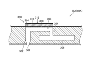
- FIG. 1A is a schematic view of forming a polyethylene glycol structure.
- FIG. 1B is a perspective view showing an example of a polyethylene glycol structure.
- FIG. 1C is a schematic diagram of forming a coating film.
- FIG. 1D is a schematic diagram of gelatin adhesion.
- FIG. 1E is a schematic diagram of gelatin adhesion.
- FIG. 1F is a schematic view of curing and dissolution.
- FIG. 1G is a schematic view of container removal.
- FIG. 1H is a schematic diagram of solid gelatin.
- FIG. 1I is a schematic view of a gelatin structure.
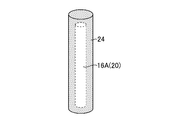
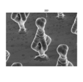
- FIG. 2 is an explanatory view of a polyethylene glycol pillar.
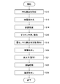
- FIG. 3 is a flowchart showing the procedure of the gelatin structure manufacturing method.
- FIG. 3 is a flowchart showing the procedure of the gelatin structure manufacturing method.
- FIG. 4 is a block diagram showing a schematic configuration of the gelatin structure manufacturing system.
- FIG. 5 is an overall configuration diagram of the polyethylene glycol structure forming part.
- FIG. 6 is a block diagram of a control system in the polyethylene glycol structure forming unit.
- FIG. 7 is a schematic configuration diagram of the coating film forming portion.
- FIG. 8A is a schematic view of fine particle gelatin injection.
- FIG. 8B is a schematic view of a polyethylene glycol structure in which fine particulate gelatin is adhered to the entire surface.
- FIG. 8C is a partially enlarged view of FIG. 8B.
- FIG. 8D is a schematic view of a polyethylene glycol structure having a coating film formed around it.
- FIG. 8E is a partially enlarged view of FIG. 8D.
- FIG. 8A is a schematic view of fine particle gelatin injection.
- FIG. 8B is a schematic view of a polyethylene glycol structure in which fine particulate gelatin is adhered
- FIG. 9 is an enlarged view of the gelatin structure after the hardening dissolution process.
- FIG. 10 is an overall configuration diagram of another form of the polyethylene glycol structure forming part.
- FIG. 11A is a plan view showing an arrangement of nozzle portions of the liquid discharge head.
- FIG. 11B is a plan view of the nozzle surface showing the arrangement of other nozzle portions of the liquid ejection head.
- FIG. 12 is a cross-sectional view showing a three-dimensional configuration of the liquid discharge head.
- FIG. 13 is a block diagram of a control system in the polyethylene glycol structure forming unit shown in FIG.
- FIG. 14 is a flowchart showing the procedure of another embodiment of the gelatin structure manufacturing method.
- FIG. 15A is a schematic diagram of formation of a single polyethylene glycol pillar.
- FIG. 15A is a schematic diagram of formation of a single polyethylene glycol pillar.
- FIG. 15A is a schematic diagram of formation of a single polyethylene glycol pillar.
- FIG. 15B is a schematic view of forming a plurality of polyethylene glycol pillars.
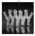
- FIG. 15C is an electron micrograph showing a vertical polyethylene glycol pillar when polyethylene glycol in which PEG 20000 and PEG 4000 are mixed is used.
- FIG. 15D is an electron micrograph showing a vertical polyethylene glycol pillar when a single PEG 4000 is used.
- FIG. 16A is a schematic view of forming a single inclined polyethylene glycol pillar.
- FIG. 16B is a schematic view of formation of a plurality of inclined polyethylene glycol pillars.
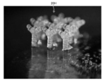
- FIG. 16C is an electron micrograph showing an inclined polyethylene glycol pillar when polyethylene glycol in which PEG 20000 and PEG 4000 are mixed is used.
- FIG. 16A is a schematic view of forming a single inclined polyethylene glycol pillar.
- FIG. 16B is a schematic view of formation of a plurality of inclined polyethylene glycol pillars.
- FIG. 16C is an
- FIG. 16D is an electron micrograph showing the results for a single PEG4000.
- FIG. 17 is an explanatory diagram of another embodiment of forming a polyethylene glycol structure.
- FIG. 18 is an explanatory diagram of another embodiment of forming a polyethylene glycol structure.
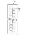
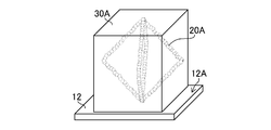
- FIG. 19 is an explanatory diagram of forming a polyethylene glycol structure having a pseudo-octahedral structure.
- FIG. 20 is an explanatory diagram of another embodiment of forming a polyethylene glycol structure.
- FIG. 21 is an explanatory diagram of forming a polyethylene glycol structure having a pseudo-octahedral structure.
- FIG. 22A is a schematic diagram of a fine particle gelatin adhesion step.
- FIG. 22A is a schematic diagram of a fine particle gelatin adhesion step.
- FIG. 22B is a schematic diagram of a polyethylene glycol structure having a pseudo-octahedral structure with a coating film formed thereon.
- FIG. 22C is a schematic diagram of solid gelatin.
- FIG. 22D is a schematic diagram of solid gelatin having a three-dimensional shape of a polyethylene glycol structure transferred therein.
- FIG. 23A is an electron micrograph of a polyethylene glycol structure.
- FIG. 23B is a schematic view of a polyethylene glycol structure.
- FIG. 24A is an electron micrograph of a polyethylene glycol structure.
- FIG. 24B is a schematic view of a polyethylene glycol structure.
- FIG. 25A is an electron micrograph of a polyethylene glycol structure.
- FIG. 25B is a schematic view of a polyethylene glycol structure.
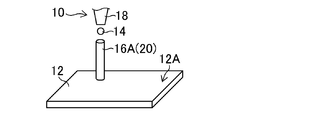
- FIG. 1A is a schematic view of forming a polyethylene glycol structure.
- PEG is a term that represents polyethylene glycol.
- the PEG structure 20 is formed by ejecting the PEG droplet 14 in a droplet state from the jet dispenser 10 toward the liquid landing surface 12A of the substrate 12.
- a vertical PEG pillar 16 ⁇ / b> A is illustrated as the PEG structure 20.
- the jet dispenser 10 includes a nozzle unit 18 that discharges PEG in a droplet state.
- PEG applied to the formation of the vertical PEG pillar 16A is solid at room temperature and has thermoplasticity.
- the PEG applied to the formation of the vertical PEG pillar 16A includes a temperature adjustment range of the heating device, or a temperature setting range including a temperature exceeding the melting point of PEG.
- the PEG applied to the formation of the vertical PEG pillar 16A is adjusted in temperature by a heating device that can be adjusted to a temperature of 60 ° C. or higher and 130 ° C. or lower, and is in a liquid state when discharged from the nozzle portion 18 of the jet dispenser 10. It is adjusted to a viscosity range that can be discharged from the jet dispenser 10.
- the normal temperature in the gelatin structure manufacturing method according to the present embodiment can be set to, for example, 5 ° C. or more and 35 ° C. or less.
- the temperature adjustment by the heating device can be a temperature adjustment process for adjusting the temperature of the PEG discharged from the nozzle portion.
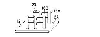
- FIG. 1B is a perspective view showing an example of a polyethylene glycol structure.
- FIG. 1B shows the PEG structure 20 formed on the liquid landing surface 12 ⁇ / b> A of the substrate 12.
- the PEG structure 20 shown in FIG. 1B has a structure in which a plurality of vertical PEG pillars 16A and a plurality of horizontal PEG pillars 16B are combined.
- the vertical PEG pillar 16A corresponds to a vertical portion.
- the horizontal PEG pillar 16B corresponds to a horizontal portion.
- the vertical PEG pillar 16A shown in FIG. 1B is formed along a direction parallel to the liquid landing surface 12A of the substrate 12 and orthogonal to the formation direction of the vertical PEG pillar 16A.
- parallel includes substantial parallel that has the same effect as parallel, although two directions intersect.
- orthogonal in the present specification is substantially the same as the case of intersecting at 90 degrees among the case of intersecting at an angle exceeding 90 degrees or the case of intersecting at an angle of less than 90 degrees. Orthogonal is included.
- the same term in this specification includes substantially the same that can obtain the same effect as the same although there is a difference in the target configuration.
- the PEG structure 20 shown in FIG. 1B has a shape corresponding to the three-dimensional shape of the hollow part of the gelatin structure shown in FIG.
- the hollow portion is illustrated in FIG.
- FIG. 1B illustrates the PEG structure 20 having the vertical PEG pillar 16A and the horizontal PEG pillar 16B, but the PEG structure 20 having only the vertical PEG pillar 16A and the horizontal PEG The PEG structure 20 having only the pillar 16B may be formed. Further, oblique PEG pillars formed along the direction intersecting the vertical PEG pillar 16A or the horizontal PEG pillar 16B may be combined.
- the three-dimensional shape of the PEG structure 20 is determined corresponding to the three-dimensional shape of the hollow portion of the gelatin structure.
- FIG. 2 is an explanatory diagram of a polyethylene glycol pillar.
- the same components as those described above are denoted by the same reference numerals, and description thereof will be omitted as appropriate.
- a plurality of vertical PEG pillars 16A shown in FIG. 1B are formed.
- the plurality of vertical PEG pillars 16A shown in FIG. 2 are arranged at predetermined arrangement intervals along the X direction and the Y direction.
- the jet dispenser 10 and the substrate 12 shown in FIG. 1A are positioned.
- the PEG droplet 14 shown in FIG. 1A is discharged from the jet dispenser 10.
- the jet dispenser 10 and the substrate 12 are relatively moved a plurality of times in the Z direction, and a plurality of ejections are executed.
- the plurality of PEG droplets 14 are stacked along the Z direction, and the plurality of PEG droplets 14 are united and cured to form the vertical PEG pillar 16A having the cylindrical shape shown in FIG. Is done.
- the X direction is an aspect parallel to the liquid landing surface of the substrate.
- the Y direction is another aspect of the direction parallel to the liquid landing surface of the substrate.
- the Z direction corresponds to the normal direction of the liquid landing surface of the substrate.
- PEG is solid at room temperature, and the PEG droplet 14 is cured immediately upon landing on the liquid landing surface 12A of the substrate 12. Further, when the PEG droplet 14 discharged next hits the PEG droplet 14 that has landed and hardened on the liquid landing surface 12A of the substrate 12 first, the PEG droplet 14 that has landed on the PEG droplet 14 immediately Harden.
- the jet dispenser 10 and the substrate 12 shown in FIG. 1A are relatively moved, and the landing position of the PEG droplet 14 on the liquid landing surface 12A of the substrate 12 And a plurality of PEG droplets 14 are sequentially stacked along the Z direction at the changed landing position, thereby forming the vertical PEG pillar 16A.
- the relative movement of the jet dispenser 10 and the substrate 12 in the X direction, the Y direction, and the Z direction and the stacking of the plurality of PEG droplets 14 are sequentially repeated, so that the plurality of vertical PEGs shown in FIG. A pillar 16A is formed.
- the relative movement between the jet dispenser 10 and the substrate 12 is synonymous with the relative movement between the nozzle portion 18 and the substrate 12.
- the diameter of the vertical PEG pillar 16A shown in FIG. 2 is 300 micrometers.
- the diameter of the vertical PEG pillar 16A is determined based on the ejection volume of the PEG droplet 14 and the wettability of the liquid landing surface 12A of the substrate 12.
- the diameter of the vertical PEG pillar 16A can be adjusted by adjusting the ejection volume of the PEG droplet 14.
- Micro is an auxiliary unit representing 10 ⁇ 6 .
- the diameter of the vertical PEG pillar 16A is synonymous with the width of the vertical PEG pillar 16A.
- the horizontal PEG pillar 16B shown in FIG. 1B is formed in the same procedure as the vertical PEG pillar 16A by changing the posture of the substrate 12 on which the vertical PEG pillar 16A is formed so that the liquid landing surface 12A is parallel to the Z direction. It is possible.
- the horizontal PEG pillar 16B moves the jet dispenser 10 and the substrate 12 relative to each other in the direction orthogonal to the formation direction of the vertical PEG pillar 16A, and moves the PEG liquid along the direction orthogonal to the formation direction of the vertical PEG pillar 16A. It is formed by laminating drops 14.
- the PEG structure 20 composed of the plurality of vertical PEG pillars 16A and the plurality of horizontal PEG pillars 16B shown in FIG. 1B. Can be formed.
- the diameter of the horizontal PEG pillar 16B is determined based on the ejection volume of the PEG droplet 14 and the wettability of the vertical PEG pillar 16A. When the wettability of the vertical PEG pillar 16A is uniform, the diameter of the horizontal PEG pillar 16B can be adjusted by adjusting the ejection volume of the PEG droplet 14. The diameter of the horizontal PEG pillar 16B is synonymous with the width of the horizontal PEG pillar 16B.
- FIG. 1C is a schematic view of coating film formation.
- a humidity range in which the dissolution of the PEG structure 20 does not proceed is set as the humidity condition, and the first humidification is performed in which the surface is covered with minute water droplets.
- a process is included.
- a humidity condition where the dissolution of the PEG structure 20 does not proceed when the diameter of the PEG structure 20 is 200 micrometers and the length of the PEG structure 20 is 1 millimeter, the relative humidity at 25 ° C. is 90%.
- a humidity condition in which the humidification period is one minute can be mentioned.
- the coating film formation shown in FIG. 1C includes a fine particle gelatin spraying step in which fine particle gelatin 22 is sprayed and adhered around the PEG structure 20.
- fine particle gelatin 22 there is an example in which fish gelatin is refined by a refiner such as a bead mill to have an average diameter of 50 micrometers.
- the average diameter of the fine particle gelatin 22 can be appropriately changed according to the shape and size of the PEG pillar 16.
- the diameter of the fine particulate gelatin 22 is the diameter of the sphere obtained from the volume of the fine particulate gelatin 22 with the shape of the fine particulate gelatin 22 regarded as a sphere.
- the average diameter of the fine particulate gelatin 22 is an average value of the diameters of the plurality of fine particulate gelatins 22 included in the unit volume.
- the average diameter of the fine particulate gelatin 22 may be a value set in a refiner.
- the fine particulate gelatin 22 is an embodiment of particulate gelatin.
- a part of the fine particulate gelatin 22 attached to the surface of the PEG structure 20 is dissolved by humidification, and the coating film 24 is formed around the PEG structure 20.
- a second humidification step The same humidity conditions as in the first humidification step can be applied as the humidity conditions in the second humidification step.
- forming the coating film includes a depressurization step in which the PEG structure 20 having the coating film 24 formed around is placed in a reduced pressure environment to promote drying of the coating film 24. If it is not necessary to promote drying of the coating film 24, the decompression step can be omitted.
- the first humidification step and the second humidification step may be the humidification step without distinguishing both when the humidity conditions are the same. That is, in the coating film formation shown in FIG. 1C, humidification is performed under a preset humidity condition, fine particulate gelatin 22 is adhered to the surface of the PEG structure 20, and further humidification is continued to further increase the PEG structure.
- the step of forming a coating film of gelatin around 20 may be possible.
- a coating film having a desired thickness can be formed by repeating the first humidification step, the fine particle gelatin spraying step, and the second humidification step a plurality of times. For example, when a fine particle gelatin having an average diameter of 50 micrometers is attached once, a coating film having a thickness of 100 micrometers is formed. A coating film having a thickness of 200 micrometers is formed by performing the first humidification step, the fine particulate gelatin adhesion step, and the second humidification step twice. The thickness of the coating film can be measured using an electron microscope.
- the PEG structure 20 in which the coating film 24 is formed around the periphery shown in FIG. 1C is an embodiment of the PEG structure 20 and an embodiment of a biocompatible material structure.
- the PEG structure 20 includes the PEG structure 20 on which the coating film 24 is formed, and the PEG structure 20 on which the coating film 24 is formed may be referred to as a PEG structure 20. .
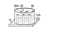
- FIG. 1D and FIG. 1E are schematic diagrams of gelatin adhesion. As shown in FIG. 1D, the entire PEG structure 20 is covered with a container 36.
- the container 36 has a shape corresponding to the outer shape of the gelatin structure that is the final product.
- the gelatin structure that is the final product is illustrated in FIG.
- the container 36 shown in FIG. 1D is sized to accommodate the entire PEG structure 20, and has an opening 36A into which a gelatin liquid can be poured.
- the substrate 12 and the container 36 may be integrated. Resin can be applied to the material of the container 36.
- the gelatin solution 30 is poured into the container 36 from the opening 36A of the container 36 as shown in FIG. 1E.
- An example of the gelatin solution 30 is a gelatin solution having a fish gelatin content of 12 mass percent.
- Fish gelatin is fish-derived gelatin.
- fish gelatin having a melting temperature of 23 ° C. is applied.
- FIG. 1F is a schematic diagram of curing and dissolution.
- cooling is performed under a preset temperature condition, and the gelatin liquid 30 in the container 36 is hardened into a gel.
- An example of the cooling temperature condition is 4 ° C.
- Another example of the cooling temperature is 15 ° C. It was confirmed that gelatin solution 30 having a temperature of 25 ° C. and having a concentration of 25 mass percent was placed in a cubic container having a side of 1 centimeter and cooled in air at 15 ° C. to harden gelatin solution 30. . When the concentration of the gelatin solution 30 was 20 mass percent, it was confirmed that the gelatin solution 30 was hardened by cooling for 10 minutes. When the concentration of the gelatin solution 30 was 25 mass percent, it was confirmed that the gelatin solution 30 was hardened by cooling for 2 minutes.
- the moisture of the gelatin solution 30 acts on the coating film 24 shown in FIG. 1C, and the coating film 24 and the gelatin solution 30 are gradually integrated.
- the water in the coating film 24 and the gelatin liquid 30 acts on the PEG structure 20 to gradually dissolve the PEG structure 20.
- the solid gelatin represents gelatin in which at least a part of the gelatin liquid is hardened to such an extent that the shape can be maintained even when the container 36 is removed.
- the solid gelatin is preferably one in which the entire gelatin solution is hardened.
- the hardening of the gelatin solution 30 also functions as part of a shaping process for shaping the solid gelatin 30A into an outer shape corresponding to the shape of the container 36.
- the container 36 covered with the solid gelatin 30A is removed as shown in FIG. 1G.
- the removal of the container shown in FIG. 1G is a part of a shaping process for shaping the solid gelatin 30A into an outer shape corresponding to the shape of the container 36.
- a hollow portion 20A corresponding to the three-dimensional shape of the PEG structure 20 shown in FIG. 1B is formed.
- the solid gelatin 30A shown in FIG. 1H is freeze-dried, the substrate 12 is removed, and the gelatin structure 32 shown in FIG. 1I is completed.
- the gelatin structure 32 shown in FIG. 1I is insolubilized by lyophilization.
- Gelatin structure 32 may include not only solid gelatin 30A after the dry freezing process shown in FIG. 1I but also solid gelatin 30A before the dry freezing process shown in FIG. 1H.
- the solid gelatin 30A after the dry freezing treatment shown in FIG. 1I is one embodiment of the gelatin structure
- the solid gelatin 30A before the dry freezing treatment shown in FIG. 1H is another embodiment of the gelatin structure. .
- gelatin structure forming step there may be mentioned an embodiment including coating film formation shown in FIG. 1C, gelatin adhesion shown in FIG. 1E, and gelatin hardening shown in FIG. 1F.
- coating film formation shown in FIG. 1C As an embodiment of the gelatin structure forming step, there may be mentioned an embodiment including coating film formation shown in FIG. 1C, gelatin adhesion shown in FIG. 1E, and gelatin hardening shown in FIG. 1F.
- an aspect including the container placement shown in FIG. 1D and the container removal shown in FIG. 1G can be mentioned.
- the dissolution of the PEG structure 20 shown in FIG. 1F is an aspect of the dissolution process.
- FIG. 3 is a flowchart showing the procedure of the gelatin structure manufacturing method.
- FIGS. 1A to 1I will be referred to as appropriate.
- the PEG structure 20 shown in FIG. 1B is formed.
- the process proceeds to the coating film forming step S12 of FIG.
- the PEG structure forming step S10 shown in FIG. 3 is an aspect of the biocompatible material structure forming step.
- a gelatin coating film 24 is formed around the PEG structure 20, as shown in FIG. 1C.
- the process proceeds to the container placement step S14 in FIG.
- the biocompatible material structure forming step may include an embodiment including the PEG structure forming step S10 shown in FIG.
- a container 36 having a shape and structure covering the entire PEG structure 20 on which the gelatin coating film 24 is formed is placed. If the container 36 is mounted, it will progress to the gelatin adhesion process S16 of FIG.
- the gelatin solution 30 is poured into the container 36 through the opening 36A of the container 36.
- the process proceeds to the hardening dissolution step S18 of FIG.
- the gelatin solution 30 is cooled in the container 36, the hardening step in which the solid gelatin 30A shown in FIG. 1F is formed, and water is supplied to the PEG structure 20 composed of PEG having water solubility.
- the dissolution process of dissolving by acting proceeds in parallel.
- moisture derived from the solid gelatin 30A can be applied.
- the process proceeds to the container removal step S20 in FIG.
- the container removal step S20 as shown in FIG. 1G, the container 36 covering the solid gelatin 30A is removed.
- the process proceeds to the freeze-drying step S22 of FIG.
- the solid gelatin 30A is freeze-dried to remove at least a part of the moisture in the gelatin solution 30.
- the process proceeds to the substrate removing step S24 in FIG.
- the freeze-drying step S22 is an aspect of the drying step.
- FIG. 3 illustrates an example in which the dry freezing process is performed on the solid gelatin 30A to which the substrate 12 is attached. However, even if the solid gelatin 30A from which the substrate 12 is removed is subjected to the dry freezing process. Good.
- the gelatin structure forming process there is an aspect including the hardening process, the container removing process S20, and the freeze-drying process S22 among the container placement process S14, the gelatin adhesion process S16, and the hardening dissolution process S18 shown in FIG. sell.
- the container placement process S14 and the container removal process S20 shown in FIG. 3 function as components of the gelatin structure forming process and also function as components of the shaping process.
- the dissolution step may include a dissolution step in the curing dissolution step S18 shown in FIG.
- Dry freeze treatment is an aspect of the treatment in the drying process.
- FIG. 4 is a block diagram showing a schematic configuration of the gelatin structure manufacturing system.
- the gelatin structure manufacturing system whose block diagram is shown in FIG. 4 is a system for realizing the gelatin structure manufacturing method whose flowchart is shown in FIG.
- the gelatin structure manufacturing system 1 illustrated in FIG. 4 includes a PEG structure forming unit 2 that forms the PEG structure 20 illustrated in FIG. 1B, and a PEG structure 20 formed by the PEG structure forming unit 2. Gelatin is attached to the periphery of the coating film forming unit 3 for forming the coating film 24 shown in FIG. 1C and the PEG structure 20 shown in FIG. 1C to form the gelatin structure 32 shown in FIG. 1I.
- a gelatin structure forming unit 4 is provided.
- the gelatin structure forming unit 4 shown in FIG. 4 is configured to cool and harden the gelatin adhering unit 5 and the gelatin solution 30 into which the gelatin solution 30 is poured around the PEG structure 20 shown in FIG.
- a hardening / dissolving unit 6 for dissolving the PEG structure 20 by adhering moisture thereto
- a freeze-drying processing unit 7 for performing a freeze-drying process on the solid gelatin 30A.
- the gelatin structure manufacturing system 1 shown in FIG. 4 includes a shaping unit 8 for shaping the solid gelatin 30A.
- a shaping unit 8 for shaping the solid gelatin 30A is a distinction based on the function for convenience, and can be appropriately integrated and separated.
- the shaping unit 8 shown in FIG. The body forming unit 4 is integrated.
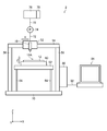
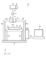
- FIG. 5 is an overall configuration diagram of the polyethylene glycol structure forming part.
- the PEG structure forming unit 2 corresponds to a biocompatible material structure forming unit.
- the PEG structure forming unit 2 shown in FIG. 5 moves the jet dispenser 10 and the substrate 12 relative to each other in the X direction, the Y direction, and the Z direction, so that the PEG structure is formed on the liquid landing surface 12A of the substrate 12. Form.
- the PEG structure forming unit 2 supports a carriage 52 that reciprocates the jet dispenser 10 along the X direction, a guide 54 that supports the carriage 52 movably along the X direction, and both ends of the guide 54 in the X direction.
- a support column 56 is provided.
- the PEG structure forming unit 2 is a table 60 that supports the substrate 12.
- the PEG structure forming unit 2 supports the table 60 that can move along the Y direction and the Z direction, a support base 62 that supports the table 60, and the support base 62.
- Leg 64 is provided. The support columns 56 and the legs 64 are placed on the base 70.
- the jet dispenser 10 is connected to a tank 76 via a flow path 72 and a pump 74.
- the tank 76 stores PEG discharged from the jet dispenser 10.
- the tank 76 includes a PEG temperature adjusting unit 78 that adjusts the temperature of the PEG.
- the tank 76 stores liquid PEG whose temperature has been adjusted by the PEG temperature adjusting unit 78.
- the table 60 includes a Y-direction moving unit that moves the substrate support unit that supports the substrate 12 along the Y direction, and a Z-direction moving unit that moves the substrate support unit along the Z direction.
- a Y-direction moving unit that moves the substrate support unit that supports the substrate 12 along the Y direction
- a Z-direction moving unit that moves the substrate support unit along the Z direction.
- illustration of the substrate support unit, the Y direction moving unit, and the Z direction moving unit is omitted.
- Examples of the Y-direction moving unit and the Z-direction moving unit include a linear moving mechanism and a vertical moving mechanism using a ball screw or a belt.
- the PEG structure forming unit 2 includes a control unit 80 that controls the operation of the carriage 52 and the operation of the table 60 and controls the ejection of the jet dispenser 10. As shown in FIG. 5, the control unit 80 is connected to a personal computer 84 via a data communication line 82. The control unit 80 receives the data of the PEG structure sent from the personal computer 84, and executes the discharge control of the jet dispenser 10, the movement control of the carriage 52, and the movement control of the table 60 based on the data of the PEG structure. .
- FIG. 5 illustrates a mode in which the control unit 80 in the PEG structure forming unit 2 and the personal computer 84 are connected by wire
- a mode in which data communication is performed by wireless connection is also possible.
- the personal computer 84 shown in FIG. 5 is arranged outside the installation location of the PEG structure forming unit 2 and the personal computer 84 and the control unit 80 of the PEG structure forming unit 2 are connected via a network. Is possible.
- FIG. 5 illustrates a mode in which the jet dispenser 10 is moved along the X direction and the substrate 12 is moved along the Y direction and the Z direction.
- the PEG structure forming unit 2 has the X direction, It is only necessary that the jet dispenser 10 and the substrate 12 can be relatively moved in the Y direction and the Z direction.
- FIG. 6 is a block diagram of a control system in the polyethylene glycol structure forming part.
- the control system shown in FIG. 6 includes the control unit 80 shown in FIG.
- the PEG structure forming unit 2 includes a system controller 100 that comprehensively controls each unit.
- the system controller 100 includes a central processing unit and a storage medium.
- the central processing unit includes what is called Central Processing Unit or CPU.
- CPU is an abbreviation for Central Processing Unit.
- the control system shown in FIG. 6 includes an ejection control unit 102, a carriage movement control unit 104, a table movement control unit 106, a temperature adjustment unit 108, and a humidity adjustment unit 110.
- the discharge control unit 102 controls droplet discharge of the jet dispenser 10 based on a command signal from the system controller 100.
- the discharge control of the jet dispenser 10 includes discharge timing control and discharge volume control.
- the carriage movement control unit 104 controls the movement of the carriage 52 shown in FIG. 5 by controlling the operation of the carriage movement unit 114 based on a command signal from the system controller 100.
- the carriage moving unit 114 illustrated in FIG. 6 includes a motor that is a drive source and a drive mechanism that is coupled to a rotation shaft of the motor.
- the table movement control unit 106 controls the operation of the table moving unit 116 to control the operation of the table 60 shown in FIG.
- the table moving unit 116 in FIG. 6 includes an X-direction moving mechanism for moving the substrate 12 shown in FIG. 5 in the X direction and a Y-direction moving mechanism for moving the substrate 12 in the X direction.
- the temperature adjustment unit 108 maintains the PEG temperature supplied to the jet dispenser 10 within a certain range suitable for PEG discharge, and the ambient temperature of the jet dispenser 10. Is configured to include an environmental temperature adjusting unit that maintains a certain range suitable for PEG ejection and PEG curing.
- the PEG temperature adjusting unit includes the PEG temperature adjusting unit 78 shown in FIG.
- the humidity adjustment unit 110 maintains the environmental humidity of the jet dispenser 10 within a certain range suitable for PEG discharge based on a command signal from the system controller 100.
- the control system shown in FIG. 6 includes a display unit 120, an operation unit 122, an input unit 124, and a storage unit 126.
- the display unit 120 displays various information based on a command signal from the system controller 100.
- a display device such as a liquid crystal display device can be applied as the display unit.
- the operation unit 122 is an operation member such as a keyboard, a mouse, or a joystick. Information input via the operation unit 122 is sent to each unit via the system controller 100.
- a mode in which the display unit 120 and the operation unit 122 are integrally formed using a touch panel type display device is also possible.
- the input unit 124 is an input interface for various information sent from outside the system.
- An example of the input unit 124 is a terminal to which the data communication line 82 shown in FIG. 5 is connected.
- a wireless communication interface may be provided as the input unit 124.
- the storage unit 126 includes a primary storage area for data, a processing area for arithmetic processing, a storage area for system parameters, and the like.
- the storage unit 126 illustrated in FIG. 6 may be configured by a plurality of storage elements.
- the control system shown in FIG. 6 stores temperature information sent from the temperature sensor 130 via the system controller 100.
- the temperature information sent from the temperature sensor 130 is used for temperature control by the temperature adjustment unit 108.
- An example of the temperature sensor 130 is a temperature sensor that detects the temperature of PEG in the jet dispenser 10.
- the control system shown in FIG. 6 stores the humidity information sent from the humidity sensor 132 via the system controller 100.
- the humidity information sent from the humidity sensor 132 is used for humidity control by the humidity adjustment unit 110.
- An example of the humidity sensor is a humidity sensor that detects the environmental humidity of the jet dispenser 10.
- control unit 80 In the control system shown in FIG. 6, the system controller 100, the discharge control unit 102, the carriage movement control unit 104, the table movement control unit 106, the temperature adjustment unit 108, and the humidity adjustment unit 110 are connected to the control unit 80 shown in FIG. included.
- control unit 80 may include another configuration in the control system shown in FIG.
- FIG. 7 is a schematic configuration diagram of the coating film forming portion.
- the coating film forming unit 3 shown in FIG. 7 includes an injection unit 202 that injects the fine particulate gelatin 22 onto the PEG structure 20 formed on the substrate 12.
- the injection unit 202 includes an injection nozzle unit 204, a gelatin flow path 206, a gelatin injection pump 208, and a gelatin tank 210.
- the fine particulate gelatin 22 is injected from the injection nozzle unit 204.
- the fine particle gelatin 22 can be adhered to the entire PEG structure 20 by moving the position of the injection nozzle unit 204 using an injection nozzle moving unit (not shown).
- the coating film forming unit 3 includes a chamber 212 that accommodates the PEG structure 20.
- the chamber 212 is configured to be able to set a temperature condition at which the dissolution of the PEG structure 20 does not proceed and a humidity condition at which the dissolution of the PEG structure 20 does not proceed.
- FIG. 8A to FIG. 8E are schematic views of coating film formation.
- FIG. 8A is a schematic view of fine particle gelatin injection.
- FIG. 8A illustrates a state in which fine particulate gelatin 22 is sprayed toward the polyethylene glycol structure 20 and the fine particulate gelatin is adhered to the PEG structure 20.
- the PEG structure 20 is humidified under a humidity condition in which the relative humidity is 90% and the humidification period is one minute.
- the diameter of the vertical PEG pillar 16A shown in FIG. 8A is 200 micrometers, and the length of the vertical PEG pillar 16A shown in FIG. 8A in the normal direction of the liquid landing surface 12A of the substrate 12 shown in FIG. And The diameter of the vertical PEG pillar 16A is synonymous with the width of the vertical PEG pillar 16A.
- the humidity conditions shown here are the same as the humidity conditions in the first humidification step in forming the coating film shown in FIG. 1C.
- FIG. 8B is a schematic diagram of a polyethylene glycol structure in which fine particulate gelatin is adhered to the entire surface.
- FIG. 8C is a partially enlarged view of FIG. 8B.
- the moisture 23 interposed between the PEG structure 20 and the fine particulate gelatin 22 functions as an adhesive, strengthens the bond between the PEG structure 20 and the fine particulate gelatin 22, and Strengthens the bond between the fine particulate gelatins 22.
- the average diameter of fine particulate gelatin is 50 micrometers.
- the diameter and average diameter of the fine particle gelatin are as described above, and the description thereof is omitted here.
- FIG. 8D is a schematic view of a polyethylene glycol structure having a coating film formed around it.
- FIG. 8E is a partially enlarged view of FIG. 8D.
- the humidity condition is such that the dissolution of the PEG structure 20 does not proceed, and the humidity condition described above is applied, the fine particulate gelatin 22 of the PEG structure 20 shown in FIG. A part of the PEG structure 20 is dissolved and united with the surrounding fine particulate gelatin 22 to form the PEG structure 20 on which the coating film 24 shown in FIG. 8D is formed.
- the coating film 24 suppresses the movement of the water molecules 30B in the gelatin solution 30 shown in FIG. 1E. Then, the progress of dissolution of the PEG structure 20 can be delayed, and the dissolution of the PEG structure 20 before the gelatin liquid 30 hardens to become solid gelatin 30A can be suppressed.
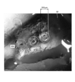
- FIG. 9 is an enlarged view of the gelatin structure after the hardening dissolution process.
- FIG. 9 is an electron micrograph in which a part of the gelatin structure 32 shown in FIG. 1I is enlarged.
- a hollow portion 20 ⁇ / b> A having a shape corresponding to the three-dimensional shape of the PEG structure 20 shown in FIG. 1B is formed inside the gelatin structure 32.
- the diameter of the hollow portion 20A shown in FIG. 9 is 300 micrometers, which is the same as the diameter of the vertical PEG pillar 16A shown in FIG.
- FIG. 9 illustrates an embodiment in which all of the PEG structure 20 shown in FIG. 1B is dissolved. However, a small amount of the PEG structure 20 remains so as not to impair the function of the gelatin structure 32. Also good.
- the thickness of the coating film 24 shown in FIG. 8D is 200 micrometers.
- the concentration of the gelatin solution 30 shown in FIG. 1E is 25 mass percent, and the temperature of the gelatin solution 30 is 25 ° C.
- the gelatin solution 30 was air-cooled at an environmental temperature of 15 ° C.
- the gelatin solution 30 could be hardened without dissolving the PEG structure 20. It was also confirmed that the three-dimensional shape of the PEG structure 20 was transferred inside the gelatin structure 32.
- the thickness of the coating film 24 shown in FIG. 8D is 200 micrometers.
- the concentration of the gelatin solution 30 shown in FIG. 1E is 20 mass percent, and the temperature of the gelatin solution 30 is 25 ° C.
- the gelatin solution 30 was air-cooled at an environmental temperature of 15 ° C.
- Example 1 it took 10 minutes for the gelatin solution 30 to harden. Further, as in Example 1, it was confirmed that the gelatin solution 30 can be cured without dissolving the PEG structure 20. It was confirmed that the three-dimensional shape of the PEG structure 20 was transferred inside the gelatin structure 32.
- the gelatin structure 32 Since the PEG structure 20 is dissolved by the water contained in the gelatin solution 30 and mixed with the gelatin solution 30 and the gelatin solution 30 is hardened, the gelatin structure 32 has a three-dimensional inverted shape of the PEG structure 20 inside. It was confirmed that it cannot be obtained.
- ⁇ Comparative Example 2> The thickness of the coating film 24 shown in FIG. 8D is 100 micrometers.
- the concentration of the gelatin solution 30 is 25 mass percent, and the temperature of the gelatin solution 30 is 25 ° C.
- the gelatin solution 30 was air-cooled at an environmental temperature of 15 ° C.
- the coating film 24 having sufficient resistance to moisture can be formed by adjusting the thickness of the coating film 24 shown in FIG. 8D.
- the thickness of the coating film 24 can be adjusted based on the concentration of the gelatin solution, the hardening condition of the gelatin solution, and the like.
- FIG. 10 is an overall configuration diagram of another form of the polyethylene glycol structure forming part.
- the difference between the PEG structure forming unit 2A shown in FIG. 10 and the PEG structure forming unit 2 shown in FIG. 5 will be described.
- the PEG structure forming unit 2A shown in FIG. 5 Description of the same configuration as the PEG structure forming unit 2 shown in FIG. 5 is omitted.
- the PEG structure forming unit 2A shown in FIG. 10 includes a liquid discharge head 10A instead of the jet dispenser 10 of the PEG structure forming unit 2 shown in FIG.
- the liquid discharge head 10A includes a plurality of nozzle portions not shown in FIG. 10, and can selectively discharge the PEG droplet 14 shown in FIG. 1A from each of the plurality of nozzle portions.
- the PEG structure forming unit 2A shown in FIG. 10 includes a control unit 80A instead of the control unit 80 of the PEG structure forming unit 2 shown in FIG. Details of the control unit 80A will be described later.
- FIG. 11A is a plan view of the nozzle surface showing the arrangement of the nozzle portion of the liquid ejection head.
- FIG. 11B is a plan view of the nozzle surface showing the arrangement of other nozzle portions of the liquid ejection head.
- Reference numeral 300 in FIG. 11A denotes a pressure chamber constituting a part of the internal flow path of the liquid ejection head 10A.
- the liquid ejection head 10B shown in FIG. 11B has two nozzle rows in which a plurality of nozzle portions 18A are arranged at equal intervals along one direction, and between one nozzle row and the other nozzle row, The position of the nozzle portion 18A in the arrangement direction of the nozzle portions 18A is shifted by a half of the nozzle arrangement interval.
- the discharge resolution in the arrangement direction of the nozzle portions of the liquid discharge head 10B shown in FIG. 11B is twice the discharge resolution in the arrangement direction of the nozzle portions of the liquid discharge head 10A shown in FIG. 11A.
- the arrangement of the nozzle portions of the liquid ejection head is not limited to the mode shown in FIGS. 11A and 11B, and a plurality of nozzle portions 18A may be arranged two-dimensionally.
- FIG. 12 is a cross-sectional view showing a three-dimensional configuration of the liquid discharge head.
- FIG. 12 illustrates one nozzle portion 18A among the plurality of nozzle portions 18A illustrated in FIG. 11A. Note that the liquid discharge head 10A shown in FIG. 11A and the liquid discharge head 10B shown in FIG. 11B have the same three-dimensional structure in one nozzle portion 18A. Here, the liquid discharge head 10A shown in FIG. explain.
- the nozzle opening 301 communicates with the pressure chamber 300 via the nozzle communication path 302.
- the pressure chamber 300 communicates with the common channel 306 through the supply port 304.
- a diaphragm 308 is formed on the ceiling surface of the pressure chamber 300.
- a piezoelectric element 310 is disposed on the side surface of the diaphragm 308 opposite to the pressure chamber 300.
- the piezoelectric element 310 has a structure in which a piezoelectric body 316 is disposed between the upper electrode 312 and the lower electrode 314. When a drive voltage is applied between the upper electrode 312 and the lower electrode 314, the piezoelectric element 310 is deformed flexibly, and the diaphragm 308 is deformed.
- liquid here is PEG of the liquid body used as the PEG droplet 14 shown to FIG. 1A.
- the piezoelectric liquid discharge head is exemplified, but a thermal liquid discharge head using a film boiling phenomenon of liquid in the pressure chamber may be applied.
- FIG. 13 is a block diagram of a control system in the polyethylene glycol structure forming part shown in FIG.
- the control system shown in FIG. 13 includes the control unit 80A shown in FIG.
- the control system shown in FIG. 13 includes a head control unit 102A instead of the ejection control unit 102 of the control system of the PEG structure forming unit 2 shown in FIG.
- the head control unit 102A controls ejection of the liquid ejection head 10A shown in FIG. 10 based on a control signal sent from the system controller 100.
- the other configuration of the control system shown in FIG. 13 is the same as the configuration of the control system shown in FIG. 6, and a description thereof is omitted here.
- FIG. 14 is a flowchart showing the procedure of another embodiment of the gelatin structure manufacturing method. 14, the same steps as those in FIG. 3 are denoted by the same reference numerals, and description thereof will be omitted as appropriate.
- a post-processing step S21 is added between the container removing step S20 and the freeze-drying step S22 shown in FIG.
- the solid gelatin 30A shown in FIG. 1H is processed into a predetermined shape. Thereafter, in the freeze-drying step S22, freeze-drying processing is performed on the post-processed solid gelatin 30A.
- the post-processing step S21 shown in FIG. 14 is a part of the components of the shaping step.
- FIG. 15A to FIG. 15D are explanatory diagrams for evaluating the stackability of polyethylene glycol droplets.
- FIG. 15A is a schematic diagram of formation of a single polyethylene glycol pillar.
- FIG. 15A schematically illustrates the formation of vertical PEG pillars 16A in which PEG droplets 14 are stacked.
- one drop of the PEG droplet 14 is discharged onto the liquid landing surface 12A of the substrate 12 and cured.
- the jet dispenser 10 is moved in the positive direction in the Z direction, that is, the normal direction of the liquid landing surface 12A of the substrate 12 and away from the substrate 12, and the distance between the PEG droplet 14 and the jet dispenser 10 is kept constant.
- the PEG droplet 14 is discharged a plurality of times.
- the moving direction of the jet dispenser 10 is illustrated using arrow lines in FIG. 15B.
- the vertical PEG pillar 16A is formed along the normal direction of the liquid landing surface 12A of the substrate 12.
- FIG. 15B is a schematic view of forming a plurality of polyethylene glycol pillars.
- the jet dispenser 10 and the substrate 12 are relatively moved along the direction parallel to the liquid landing surface 12A of the substrate 12 and arranged at equal intervals.
- an example is shown in which a plurality of vertical PEG pillars 16A are formed at intervals of 1 millimeter.
- the arrangement interval of the plurality of vertical PEG pillars 16A can be an arbitrary value as long as it is a value exceeding the diameter of the adjacent vertical PEG pillar 16A.
- the arrow line shown in FIG. 15B is the moving direction of the jet dispenser 10 in a plane parallel to the liquid landing surface 12 ⁇ / b> A of the substrate 12.
- the moving direction of the jet dispenser 10 may be the X direction shown in FIG. 5 or the Y direction. It may be an oblique direction intersecting the X direction and the Y direction.
- the PEG discharge speed in the jet dispenser 10 was 10 millimeters per second, the PEG discharge interval was 5 seconds, and 40 PEG droplets 14 were discharged at the position where one vertical PEG pillar 16A was formed.
- Evaluation A in [Table 1] above indicates that normal discharge is possible within the temperature adjustable range of the jet dispenser 10.
- the normal discharge means that a PEG droplet having a volume within a predetermined range with respect to the discharge command has landed on the substrate.
- Evaluation B is a case where normal ejection cannot be performed, and the PEG droplet landed on the substrate, but the volume of the PEG droplet landed on the substrate is less than a predetermined volume, or the PEG droplet landed on the substrate This represents a case where the volume exceeds a predetermined volume.
- the temperature exceeding the melting point of PEG is not included in the temperature adjustable range of the jet dispenser 10, and PEG does not melt.
- the jet dispenser 10 and the substrate 12 shown in FIG. 15A are mounted on a robot configured to be movable in the X, Y, and Z directions.
- a liquid ejection device was used.
- PEG used for the evaluation of dischargeability was manufactured by Wako Pure Chemical Industries, Ltd., polyethylene glycol 10000, polyethylene glycol 40000, polyethylene glycol 20000, polyethylene glycol 10000, polyethylene glycol 6000, and polyethylene glycol 4000.
- polyethylene glycol is referred to as PEG.
- the average molecular weight distribution of PEG40000 is more than 35000 and less than 55000.
- the average molecular weight distribution of PEG 20000 is more than 15000 and less than 25000.
- the average molecular weight distribution of PEG 10000 is more than 8800 and less than 11200.
- the average molecular weight distribution of PEG 6000 is more than 5500 and less than 6500.
- the molecular weight distribution of PEG 4000 is more than 2700 and less than 3300.
- the average molecular weight distribution corresponds to the molecular weight distribution.
- K (56106 / P) ⁇ 2 where the hydroxyl value is obtained by neutralization titration, K is the average molecular weight, and P is the hydroxyl value.
- 56106 is a coefficient from the potassium hydroxide molecule. 2 is the number of hydroxyl groups.
- the neutralization titration method As the neutralization titration method, the neutralization titration method of 7.1 in the test method of JIS K 0070 can be applied.
- JIS is an abbreviation for Japanese Industrial Standards.
- the average molecular weight distribution of each PEG can be determined by GPC measurement or HPLC measurement in which the molecular weight is calculated from the hydroxyl value.
- GPC is an abbreviation for GelGPermeation Chromatography.
- HPLC is an abbreviation for High Performance Liquid Chromatography.
- the vertical series of 60 ° C. in the above [Table 1] represents the dischargeability evaluation when the temperature of each PEG is 60 ° C.
- the vertical series of 100 ° C. in the above [Table 1] represents the dischargeability evaluation when the temperature of each PEG is 100 ° C.
- the vertical series of 130 ° C. in the above [Table 1] represents the dischargeability evaluation when the temperature of each PEG is 60 ° C.
- the numerical value in parentheses in each column is the viscosity.
- the unit of viscosity is millipascal second.
- the viscosity at PEG 40000 and 100 ° C. was set to an upper limit value of 100000 millipascal seconds or more in the measurable range.
- the viscosity of PEG in this embodiment is a measured value of a viscometer.
- an EMS viscometer EMS-1000 manufactured by Kyoto Electronics Industry Co., Ltd. can be used.
- EMS is an abbreviation for Electro-Magnetically Spinning.
- the measuring method of the EMS viscometer EMS-1000 is an electronic spinning method.
- a temperature raising device capable of setting the temperature between 0 ° C. and 200 ° C. was used.
- the temperature of PEG is a temperature setting value of the temperature raising device.
- the single PEG 10000, the single PEG 6000, and the single PEG 4000 can normally discharge.
- the upper limit of the viscosity range of PEG is 5000 millipascal seconds
- the lower limit is 126 millipascal seconds.
- the single PEG is a PEG having a predetermined average molecular weight range, and is not mixed with PEG having another molecular weight range.
- the lower limit value of the discharge range in which normal discharge can be performed is the last two digits of the measured value 126 millipascal seconds, considering that the smaller the viscosity value, the easier the discharge. To 100 millipascal seconds.
- PEG 10000, PEG 6000, and PEG 4000 are first polyethylene glycols having a molecular weight distribution that can be adjusted to a viscosity range that can be discharged independently, and are one embodiment of the first biocompatible material.
- PEG 100000, PEG 40000, and PEG 20000 alone cannot perform normal ejection in a temperature range of 60 ° C. or higher and lower than 130 ° C. This is presumably because the viscosity of PEG exceeds the upper limit of the viscosity at which normal ejection can be performed.
- PEG 100000, PEG 40000, and PEG 20000 are second polyethylene glycols having a molecular weight distribution that cannot be adjusted within a viscosity range that can be discharged independently, and are one embodiment of the second biocompatible material.
- PEG in which PEG 20000 and PEG 4000 are mixed was used.
- PEG 20000 and PEG 4000 mixed as PEG, PEG 20000 80 mass percent, PEG 4000 20 mass percent mixed PEG, PEG 20000 70 mass percent, PEG 4000 30 mass percent PEG, PEG 20000 50 mass percent, PEG 4000 50 mass Percent-mixed PEG, and PEG 20000 mixed with 30 mass percent and PEG 4000 mixed with 70 mass percent were used.
- the above-mentioned four types of PEG in which PEG 20000 and PEG 4000 are mixed can normally discharge.
- the upper limit of the viscosity range of PEG is 8920 millipascal seconds, and the lower limit is 2410 millipascal seconds.
- the upper limit of the viscosity range in which normal ejection is possible taking into account the reliability of temperature adjustment and the measurement error of viscosity, the actual value of the upper limit of viscosity capable of normal ejection, 8920 millipascal seconds, and the viscosity incapable of normal ejection It is an almost intermediate value between the actually measured value of the lower limit of 13600 millipascal seconds, and a value obtained by discarding 10000 or less was adopted as 10,000 millipascal seconds.
- the lower limit value of the ejection range in which normal ejection is possible is generally the measured value 126 described in [Table 1], considering that the smaller the viscosity value, the easier the ejection. The last two digits of the millipascal second were rounded down to 100 millipascal seconds.
- 80% by weight of PEG 20000, 20% by weight of PEG 4000 mixed, 70% by weight of PEG 20000, 30% by weight of PEG 4000, 50% by weight of PEG 20000, 50% by weight of PEG 4000 or 30% by weight of PEG 20000 PEG mixed with 70 percent by weight of PEG 4000 is a third polyethylene glycol in which the second biocompatible material is mixed with the first biocompatible material at a ratio of 20 mass percent to 80 mass percent. It is an aspect of a compatible material.
- the difference in curing speed between the single PEG and the mixed PEG is considered to be due to the difference in temperature difference between the temperature at the time of discharge and the temperature at which curing begins.
- the temperature adjustment range of PEG is 60 ° C. or more and 130 ° C. or less.
- the temperature adjustment range of PEG is a temperature range including a temperature exceeding the melting point of PEG, and depends on the temperature adjustment capability of the jet dispenser. The temperature range can be adjusted in the jet dispenser.
- the temperature range in which the temperature can be adjusted in the jet dispenser should be changed as appropriate in consideration of the durability of PEG or PEG droplets that come into contact with the nozzle, substrate, etc., the ability to keep the temperature at the nozzle constant. Can do.
- the temperature range in which the temperature can be adjusted in the jet dispenser corresponds to the range in which the temperature of the PEG discharged from the nozzle can be adjusted.
- FIG. 15C is an electron micrograph showing a vertical PEG pillar when PEG in which PEG 20000 and PEG 4000 are mixed is used.
- the mixing ratio of PEG 20000 and PEG 4000 in the vertical PEG pillar 16A shown in FIG. 15C is 30 mass percent for PEG 20000 and 70 mass percent for PEG 4000.
- Found width D 1 of the vertical PEG pillar 16A shown in FIG. 15C is 0.21 mm and a height of 1.33 millimeters.
- the vertical PEG pillar 16A shown in FIG. 15C does not collapse even if pressed with a finger and does not break in the middle, and the contact portion of the vertical PEG pillar 16A with the substrate 12 does not peel off from the substrate 12. Have.
- FIG. 15D is an electron micrograph showing a vertical PEG pillar when a single PEG 4000 is used. Found width D 2 of the vertical PEG pillar 16A shown in FIG. 15D is 0.26 millimeters, measured values of the height H 2 is 0.86 millimeters.
- the single PEG 4000 has a lower viscosity than the PEG obtained by mixing the single PEG 20000 and the single PEG 4000, and the wetting spread on the liquid landing surface 12A of the substrate 12 is large.
- FIG. 16A to FIG. 16D are explanatory diagrams of evaluation of the laminating properties of polyethylene glycol droplets in an oblique direction.
- FIG. 16A is a schematic view of forming a single inclined polyethylene glycol pillar.
- FIG. 16A schematically shows the formation of an inclined PEG pillar 16C in which PEG droplets 14 are stacked in an oblique direction.
- the inclined PEG pillar 16C corresponds to an inclined portion.
- one drop of the PEG droplet 14 is discharged onto the liquid landing surface 12A of the substrate 12 and cured.
- the jet dispenser 10 is moved in an oblique direction having a component in the positive direction in the Z direction and having a component parallel to the liquid landing surface 12A of the substrate 12, and the distance between the PEG droplet 14 and the jet dispenser 10 is kept constant.
- the PEG droplet 14 is ejected a plurality of times while being shifted by a certain distance in one direction parallel to the liquid landing surface 12A of the substrate 12.
- the direction of movement of the jet dispenser 10 is illustrated using arrow lines in FIG. 16B.
- 16A is an inclined PEG pillar 16C in which the PEG droplets 14 shown in FIG. 16A are obliquely stacked, and the component in the normal direction of the liquid landing surface 12A of the substrate 12 and the liquid landing surface 12A of the substrate 12 in the direction parallel to the liquid landing surface 12A.
- An inclined PEG pillar 16C is formed along the direction having the components.
- FIG. 16B is a schematic view of forming a plurality of inclined polyethylene glycol pillars.
- the first PEG droplet 14 is landed on each of the formation positions of the plurality of PEG pillars on the liquid landing surface 12A of the substrate 12, and the first PEG liquid is dropped.
- the droplet 14 is cured, and the second PEG droplet 14 is landed on the first PEG droplet 14 at each PEG pillar forming position.
- the landing position of the second PEG droplet 14 is shifted by 0.075 mm from the first PEG droplet 14 in the direction parallel to the liquid landing surface 12A of the substrate 12.
- the second PEG droplet 14 is cured, and the movement and ejection of the jet dispenser 10 are repeated to form a plurality of inclined PEG pillars 16C shown in FIG. 16B.
- the arrangement interval of the plurality of inclined PEG pillars 16C is 1 millimeter.
- FIG. 16C is an electron micrograph showing an inclined polyethylene glycol pillar when polyethylene glycol in which PEG 20000 and PEG 4000 are mixed is used.
- the mixing ratio of PEG 20000 and PEG 4000 in the inclined PEG pillar 16C shown in FIG. 16C is 30 mass percent for PEG 20000 and 70 mass percent for PEG 4000.
- FIG. 16C shows the case where the PEG temperature is 100 ° C., but it has been confirmed that the same result can be obtained when the PEG temperature is 130 ° C. In addition, it has been confirmed that similar results can be obtained for the four types of PEGs shown in Table 2 above.
- FIG. 16D is an electron micrograph showing the results for a single PEG4000.
- the PEG viscosity is low and the PEG 4000 tends to sag so that the inclined PEG pillar 16C inclined in the oblique direction shown in FIG. 16D could not be formed.
- a reference numeral 16D in FIG. 16D illustrates a plurality of PEG droplets dripped and united on the liquid landing surface 12A of the substrate 12.
- the first PEG in the above [Table 3] represents the first polyethylene glycol.
- the first polyethylene glycol is a general term for a single PEG 10000, a single PEG 6000, or a single PEG 4000.
- the third PEG in [Table 3] above represents the third polyethylene glycol.
- the numerical range shown in the above [Table 3] is the viscosity of PEG.
- the unit is millipascal second.
- the 60-degree inclined lamination in the above [Table 3] indicates that it is possible to form the inclined PEG pillar 16C along the direction in which the inclination angle with respect to the liquid landing surface 12A of the substrate 12 is 60 degrees.
- the 30-degree inclined lamination in the above [Table 3] indicates that it is possible to form the inclined PEG pillar 16C along the direction in which the inclination angle with respect to the liquid landing surface 12A of the substrate 12 is 30 degrees.
- the first PEG can form the vertical PEG pillar 16A along the normal direction of the liquid landing surface 12A of the substrate 12 when the viscosity range is 100 millipascal seconds or more and 5000 millipascal seconds or less.
- the viscosity range is 4000 millipascal seconds or more and 5000 millipascal seconds or less, it is possible to form the inclined PEG pillar 16C along the direction in which the inclination angle with respect to the liquid landing surface 12A of the substrate 12 is 60 degrees. It is.
- the first PEG does not have a viscosity range in which the tilted PEG pillar 16C can be formed along the direction in which the tilt angle with respect to the direction parallel to the liquid landing surface 12A of the substrate 12 is 30 degrees.
- the third PEG can form the vertical PEG pillar 16A along the normal direction of the liquid landing surface 12A of the substrate 12 when the viscosity range is 100 millipascal seconds or more and 10,000 millipascal seconds or less.
- the third PEG when the viscosity range is 500 millipascal seconds or more and 10,000 millipascal seconds or less, it is possible to form the inclined PEG pillar 16C along the direction in which the inclination angle with respect to the liquid landing surface 12A of the substrate 12 is parallel to the direction of 60 degrees. It is.
- the third PEG when the viscosity range is 2000 millipascal seconds or more and 10,000 millipascal seconds or less, it is possible to form the inclined PEG pillar 16C along the direction in which the inclination angle with respect to the liquid landing surface 12A of the substrate 12 is parallel to the direction of 30 degrees. It is.
- the third PEG is an inclined PEG along a direction in which the inclination angle with respect to the direction parallel to the liquid landing surface 12A of the substrate 12 is 30 degrees or more and less than 60 degrees when the viscosity range is 2000 milliseconds or more and 10,000 milliseconds or less.
- the pillar 16C can be formed.
- the viscosity range condition of the PEG that can be laminated is derived for the discrete molecular weight and the discrete temperature, but the viscosity of the PEG is simply increased or decreased with respect to the increase or decrease of the molecular weight.
- the viscosity of PEG is a simple decrease or a simple increase with respect to the temperature increase and decrease, the molecular weight between the discrete values and the temperature can be obtained the same result as the discrete values. Predictable.
- the viscosity range shown in the above [Table 3] is derived by appropriately rounding off, rounding up, or rounding off the measured value in consideration of measurement error, intervals of discrete numerical values used for the measurement, and the like. .
- the difference between the viscosity range in which the first PEG laminate can be formed and the viscosity range in which the first PEG laminate can be formed is that the curing rate of the first PEG and the curing rate of the third PEG It is thought to be caused by the difference.
- the PEG curing rate after landing on the substrate tends to increase as the molecular weight increases.
- the third PEG has a faster curing speed after landing on the substrate than the first PEG, and a good laminate was formed.
- a mixed PEG of PEG 20000 and PEG 4000 is exemplified as the third PEG, but a mixed PEG of PEG 20000 and PEG 6000 or a mixed PEG of PEG 20000 and PEG 10000 can be used as the third PEG.
- the third PEG is constituted.
- the type of the first PEG and the type of the second PEG to be performed are not limited to the PEG exemplified in this embodiment.
- the substrate 12 In the evaluation of the stackability of the PEG droplet 14 shown in the present embodiment, a glass substrate was used as the substrate 12. When a material having water repellency with respect to PEG, such as an acrylic plate, is applied to the substrate 12, the adhesion of the PEG to the substrate 12 is low, and the PEG collapses or breaks at the contact surface between the PEG and the substrate 12. . Therefore, the substrate 12 is made of a material having hydrophilicity with respect to PEG such as glass.
- hydrophilicity with respect to PEG means that the contact angle exceeds 90 degrees
- hydrophobicity with respect to PEG means that the contact angle is 90 degrees or less.
- the viscosity can be discharged from the nozzle part, and using PEG adjusted to the viscosity that can be laminated, a PEG structure composed of PEG having a three-dimensional structure is formed To do.
- PEG structure adjusts the viscosity of PEG by mixing PEG with molecular weight distribution that can be ejected from the nozzle part alone with PEG having molecular weight distribution that cannot be ejected from the nozzle part alone By doing so, it is possible to form a PEG structure along an oblique direction with respect to the liquid landing surface 12A of the substrate 12.
- FIG. 17 is an explanatory diagram of another embodiment of forming a polyethylene glycol structure.
- FIG. 17 shows a PEG structure 20B having a structure in which two inclined PEG pillars 16C are joined at a position where the distance from the substrate 12 is maximized.
- FIG. 17 schematically illustrates the procedure for forming the PEG structure 20 ⁇ / b> B using the jet dispenser 10 shown using a two-dot broken line and an arrow line.
- the liquid ejection head 10A including the plurality of nozzles illustrated in FIG. 10 is applied to the formation of the PEG structure 20B illustrated in FIG. 17, the relative position between the substrate 12 and the liquid ejection head 10A is not changed.
- the PEG structure 20B shown in FIG. 17 can be formed by changing the nozzle portion used for ejection to the nozzle portion corresponding to the position where the PEG is landed.
- the diameter of the PEG droplet 14 was set to 200 micrometers or more and 250 micrometers or less.
- the diameter of the PEG droplet 14 is a diameter of a sphere derived by regarding the PEG droplet 14 as a sphere and taking the volume of the PEG droplet 14 as the volume of the sphere.
- the volume of the PEG droplet 14 is 100 picoliters or more and 10 nanoliters or less.
- pico is an auxiliary unit representing 10-12 .
- Nano is an auxiliary unit representing 10 ⁇ 9 .
- FIG. 18 is an explanatory diagram of another embodiment of forming a polyethylene glycol structure.
- FIG. 18 shows a PEG structure 20C having a structure in which the tilt direction is changed at an intermediate position.
- the PEG structure 20C shown in FIG. 18 has a structure in which inclined PEG pillars 16C having different inclination directions are joined in the normal direction of the liquid landing surface 12A of the substrate 12.
- FIG. 19 is an explanatory view of forming a polyethylene glycol structure having a pseudo octahedral structure, and is an electron micrograph of the PEG structure.
- a PEG structure 20D shown in FIG. 19 has a structure in which a plurality of PEG structures 20B shown in FIG. 17 are combined or a structure in which a plurality of PEG structures 20C shown in FIG. 18 are combined.
- the PEG structure 20D shown in FIG. 19 can be regarded as a pseudo octahedron due to the eight surfaces that form the outer periphery of the PEG structure 20D.
- FIG. 20 is an explanatory diagram of another embodiment of forming a polyethylene glycol structure.
- the inclined PEG pillar 16E having an inclination angle smaller than the inclination angle of the inclined PEG pillar 16C shown in FIG. 18 with respect to the liquid landing surface 12A of the substrate 12 is used.
- the angle formed by the two inclined PEG pillars 16E is 90 degrees.
- 90 degrees includes substantial 90 degrees from which an effect similar to that of 90 degrees can be obtained among angles less than 90 degrees and angles exceeding 90 degrees.
- the PEG structure 20E shown in FIG. 20 is a PEG structure having a structure in which the inclination direction is changed at an intermediate position, similar to the PEG structure 20C shown in FIG. This is a PEG structure having a structure in which the pillar 16C is bonded in the normal direction of the liquid landing surface 12A of the substrate 12.
- FIG. 21 is an explanatory view of forming a polyethylene glycol structure having a pseudo-octahedral structure, and is an electron micrograph of the PEG structure.
- the PEG structure 20F shown in FIG. 21 has a structure in which a plurality of PEG structures 20E shown in FIG. 20 are combined.
- the PEG structure 20F shown in FIG. 21 can be regarded as a pseudo regular octahedron by the eight surfaces constituting the outer periphery of the PEG structure 20F.
- FIG. 22A to FIG. 22D are schematic views showing a procedure for producing a gelatin structure using a polyethylene glycol structure having a pseudo-octahedral structure.
- FIG. 22A is a schematic diagram of a fine particle gelatin adhesion step.
- FIG. 22A is the PEG structure 20F shown in FIG. 21, in which a PEG structure 20F having a pseudo-octahedral structure is formed on the liquid landing surface 12A of the substrate 12 and fine particulate gelatin 22 is adhered. The adhesion process is shown.
- FIG. 22B is a schematic view of a polyethylene glycol structure having a pseudo-octahedral structure on which a coating film is formed.
- FIG. 22B shows a state in which the fine particle gelatin 22 is adhered to the entire periphery of the PEG structure 20F having a pseudo-octahedron structure and the coating film 24 is formed.
- FIG. 22C is a schematic diagram of solid gelatin.
- 22C shows the PEG structure 20F shown in FIG. 22B.
- the gelatin solution 30 is attached to the PEG structure 20F having the coating film 24 formed on the entire periphery, and the gelatin solution 30 is solidified to form solid gelatin.
- a state in which 30A is formed is illustrated.
- FIG. 22D is a schematic view of solid gelatin having a three-dimensional shape of a polyethylene glycol structure transferred therein.
- FIG. 22D shows a solid gelatin 30A in which the PEG structure 20F shown in FIG. 22C is dissolved and the three-dimensional shape of the PEG structure 20F is transferred to the inside.
- the solid gelatin 30A having a hollow shape corresponding to the three-dimensional shape of the PEG structure is formed using the PEG structure having an arbitrary three-dimensional structure as a template.
- FIG. 23A to FIG. 25D are explanatory views of another embodiment of PEG structure formation.
- FIG. 23A is an electron micrograph of the PEG structure
- FIG. 23B is a schematic diagram of the polyethylene glycol structure.
- the PEG structure 20G shown in FIGS. 23A and 23B has a combination of the vertical PEG pillar 16A shown in FIGS. 1A to 1I and the two inclined PEG pillars 16C shown in FIG. Yes.
- the inclination angle of the substrate 12 with respect to the liquid landing surface 12A is 13 degrees.
- the broken line illustrated in FIG. 23B indicates a surface parallel to the liquid landing surface 12A of the substrate 12. That is, since the inclined PEG pillar 16C can be formed even when the inclination angle of the substrate 12 with respect to the liquid landing surface 12A is less than 30 degrees, the inclination angle of the substrate 12 with respect to the liquid landing surface 12A even when there is PEG variation. Can form a tilted PEG pillar 16C having an angle of 30 degrees or more.
- the width of the vertical PEG pillar 16A constituting the PEG structure 20G shown in FIG. 23A and FIG. 23B can be 250 micrometers or more and 300 micrometers or less.
- FIG. 24A and FIG. 24B are explanatory views of another embodiment of forming a polyethylene glycol structure.
- FIG. 24A is an electron micrograph of a polyethylene glycol structure
- FIG. 24B is a schematic diagram of the polyethylene glycol structure.
- the inclined PEG pillar 16C constituting the PEG structure 20H has an inclination angle of 69 degrees with respect to the liquid landing surface 12A of the substrate 12.
- the broken line illustrated in FIG. 24B indicates a surface parallel to the liquid landing surface 12A of the substrate 12.
- the width of the vertical PEG pillar 16A constituting the PEG structure 20H shown in FIGS. 24A and 24B can be 250 micrometers or more and 300 micrometers or less.
- FIG. 25A and FIG. 25B are explanatory views of another embodiment of forming a polyethylene glycol structure.
- FIG. 25A is an electron micrograph of a polyethylene glycol structure
- FIG. 25B is a schematic diagram of the polyethylene glycol structure.
- the inclination angle of the substrate 12 with respect to the liquid landing surface 12A is 85 degrees.
- the broken line illustrated in FIG. 25B indicates a surface parallel to the liquid landing surface 12A of the substrate 12.
- the width of the vertical PEG pillar 16A constituting the PEG structure 20I shown in FIGS. 25A and 25B can be 250 micrometers or more and 300 micrometers or less.
- a PEG structure 20 having an arbitrary three-dimensional shape can be formed by combining a plurality of inclined PEG pillars. Further, as shown in FIGS. 23A to 25B, the PEG structure 20 having an arbitrary three-dimensional shape can be formed by combining the vertical PEG pillar 16A and the plurality of inclined PEG pillars 16C. Although not shown, the PEG structure 20 having an arbitrary three-dimensional shape including the horizontal PEG pillar 16B shown in FIGS. 1A to 1I can be formed.
- Natural gelatin can be applied as gelatin applicable to the gelatin structure manufacturing method according to the present embodiment.
- a natural gelatin may be a variant that differs in at least one amino acid residue.
- the gelatin applicable to the method for producing a gelatin structure according to the present embodiment is based on the base sequence or amino acid sequence of a gene encoding collagen having 6 or more consecutive sequences represented by Gly-XY.
- a recombinant gelatin obtained by introducing a base sequence or amino acid sequence with one or more bases or amino acid residue changes into a suitable host and expressing it by a conventional method is preferred.
- tissue repair ability can be enhanced and various characteristics can be expressed as compared with the case of using natural gelatin. For example, adverse effects such as rejection by a living body can be exerted. It has the advantage that it can be avoided.
- Recombinant peptides can be applied as recombinant gelatin.
- Recombinant peptide means a polypeptide or protein-like substance having an amino acid sequence similar to gelatin produced by a genetic recombination technique.
- Preferred as a recombinant peptide applicable to the method for producing a gelatin structure according to this embodiment is a recombinant peptide having the following mode.
- the recombinant peptide applicable to the method for producing a gelatin structure according to the present embodiment is excellent in biocompatibility from the original performance of natural gelatin, and is not naturally derived. ing.
- BSE is an abbreviation for Bovine Spongiform Encephalopathy and represents bovine spongiform encephalopathy.
- the recombinant peptide used in the present invention is more uniform than the natural peptide and the sequence is determined, the strength and degradability can be precisely designed with less blur due to the crosslinking described later. is there.
- the molecular weight of the recombinant peptide is preferably 2,000 or more and 100,000 or less. More preferably, it is 2500 or more and 95000 or less. More preferably, it is 5000 or more and 90000 or less. Most preferably, it is 10,000 or more and 90,000 or less.
- polyethylene glycol is exemplified as the biocompatible material.
- the temperature can be adjusted in the jet dispenser or the liquid discharge head, and the material can be normally discharged at the adjusted temperature.
- a material having thermoplasticity and water solubility can be applied as the biocompatible material.
Landscapes
- Chemical & Material Sciences (AREA)
- Engineering & Computer Science (AREA)
- Health & Medical Sciences (AREA)
- Materials Engineering (AREA)
- Manufacturing & Machinery (AREA)
- Life Sciences & Earth Sciences (AREA)
- Mechanical Engineering (AREA)
- Optics & Photonics (AREA)
- Physics & Mathematics (AREA)
- Medicinal Chemistry (AREA)
- General Health & Medical Sciences (AREA)
- Animal Behavior & Ethology (AREA)
- Veterinary Medicine (AREA)
- Public Health (AREA)
- Epidemiology (AREA)
- Transplantation (AREA)
- Oral & Maxillofacial Surgery (AREA)
- Dermatology (AREA)
- Biomedical Technology (AREA)
- Biotechnology (AREA)
- Chemical Kinetics & Catalysis (AREA)
- Organic Chemistry (AREA)
- Genetics & Genomics (AREA)
- Wood Science & Technology (AREA)
- Zoology (AREA)
- Bioinformatics & Cheminformatics (AREA)
- Microbiology (AREA)
- Biochemistry (AREA)
- General Engineering & Computer Science (AREA)
- Cell Biology (AREA)
- Polymers & Plastics (AREA)
- Robotics (AREA)
- Materials For Medical Uses (AREA)
- Medicinal Preparation (AREA)
- Compositions Of Macromolecular Compounds (AREA)
Abstract
Description
図1Aから図1Iはゼラチン構造体製造方法の概要を示す模式図である。図1Aはポリエチレングリコール構造体形成の模式図である。PEGはポリエチレングリコールを表す用語である。
図3はゼラチン構造体製造方法の手順を示すフローチャートである。以下の説明では、図1Aから図1Iを適宜参照する。
図4はゼラチン構造体製造システムの概略構成を示すブロック図である。図4にブロック図を示したゼラチン構造体製造システムは、図3にフローチャートを示したゼラチン構造体製造方法を実現するシステムである。
次に、図4に示したPEG構造体形成部について詳細に説明する。図5はポリエチレングリコール構造体形成部の全体構成図である。PEG構造体形成部2は生体適合性材料構造体形成部に相当する。
次に、図4に示した被覆膜形成部3について詳細に説明する。図7は被覆膜形成部の概略構成図である。
<具体例1>
図8Dに示した被覆膜24の厚みを200マイクロメートルとする。図1Eに示したゼラチン液30の濃度を25質量パーセント、ゼラチン液30の温度を25℃とする。環境温度15℃としてゼラチン液30を空冷した。
図8Dに示した被覆膜24の厚みを200マイクロメートルとする。図1Eに示したゼラチン液30の濃度を20質量パーセント、ゼラチン液30の温度を25℃とする。環境温度15℃としてゼラチン液30を空冷した。
図8Dに示した被覆膜24を形成せずに、図1Bに示したPEG構造体20に対して、濃度が25質量パーセント、温度が25℃のゼラチン液30を付着させた。環境温度15℃としてゼラチン液30を空冷した。
図8Dに示した被覆膜24の厚みを100マイクロメートルとする。ゼラチン液30の濃度を25質量パーセント、ゼラチン液30の温度を25℃とする。環境温度15℃としてゼラチン液30を空冷した。
図10はポリエチレングリコール構造体形成部の他の形態の全体構成図である。ここでは、主として、図10に示したPEG構造体形成部2Aにおける、図5に示したPEG構造体形成部2との違いについて説明することとし、図10に示したPEG構造体形成部2Aにおいて、図5に示したPEG構造体形成部2と同一の構成の説明は省略する。
図14はゼラチン構造体製造方法の他の態様の手順を示すフローチャートである。図14において、図3と同一の工程には同一の符号を付し、説明を適宜省略する。図14に示したフローチャートでは、図3に示した容器取外し工程S20と凍結乾燥工程S22との間に後加工工程S21が追加されている。
次にPEG構造体の形成について詳細に説明する。以下に、PEG構造体を形成する際のPEGの吐出性、及びPEG液滴の積層性について詳細に説明する。
図15Aから図15Dはポリエチレングリコール液滴の積層性評価の説明図である。図15Aは一本のポリエチレングリコールピラー形成の模式図である。図15Aには、PEG液滴14を積み重ねた垂直PEGピラー16Aの形成が模式的に図示されている。


次に、PEG液滴の積層性評価について説明する。上記[表1]、及び[表2]に示したPEG液滴の吐出性評価の結果がAの場合、すなわち、正常吐出が可能なPEGについて、積層性評価を行った。
図16Aから図16Dはポリエチレングリコール液滴の斜め方向の積層性評価の説明図である。図16Aは一本の傾斜ポリエチレングリコールピラー形成の模式図である。図16Aには、PEG液滴14を斜め方向に積層させた傾斜PEGピラー16Cの形成が模式的に図示されている。傾斜PEGピラー16Cは傾斜部に相当する。
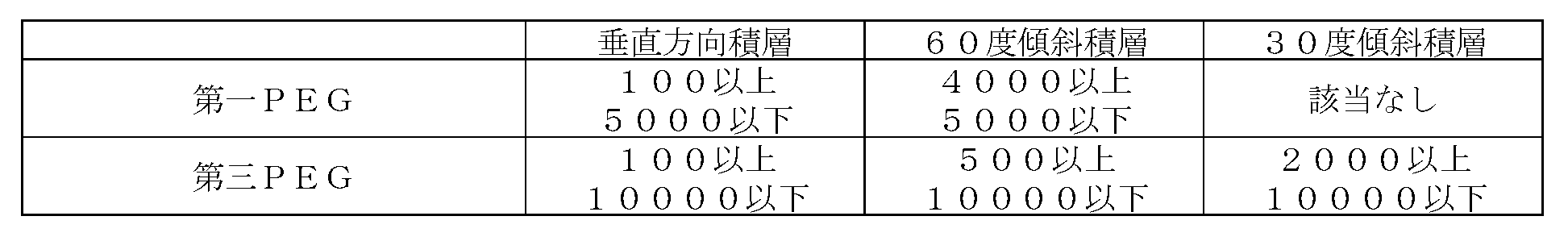
本実施形態に示したPEG液滴14の積層性評価には、基板12としてガラス製基板を用いた。アクリル板などPEGに対して撥水性を有する材料を基板12に適用した場合、PEGの基板12に対する密着性が低く、PEGと基板12との接触面において、PEGの崩れや折れが発生してしまう。したがって、基板12はガラスなどPEGに対する親水性を有する材料が適用される。
上記の如く構成されたゼラチン構造体製造方法によれば、医療分野で利用実績が高いPEGによる立体構造物であるPEG構造体の作製は、液滴吐出型のディスペンサー、又はインクジェットヘッド方式の液体吐出ヘッドにより可能である。これを鋳型として用いることで、ゼラチンの反転構造の形成が可能となった。
図17はポリエチレングリコール構造体形成の他の実施形態の説明図である。図17には、二本の傾斜PEGピラー16Cを、基板12からの距離が最大となる位置で接合させた構造を有するPEG構造体20Bを示した。
本実施形態に係るゼラチン構造体製造方法に適用可能なゼラチンとして、天然型ゼラチンを適用することができる。天然型ゼラチンとは少なくとも1つのアミノ酸残基が異なる変異型であってもよい。また、本実施形態に係るゼラチン構造体製造方法に適用可能なゼラチンは、Gly-X-Yで示される配列を連続して6以上有するコラーゲンをコードする遺伝子の塩基配列又はアミノ酸配列に対して、1つ以上の塩基又はアミノ酸残基の変更を加えた塩基配列又はアミノ酸配列を、常法により、適当な宿主に導入し発現させて得られた組換えゼラチンであることが好ましい。このような組換えゼラチンを用いることにより、組織修復能を高めると共に、天然のゼラチンを用いる場合と比較して種々の特性を発現させることができ、例えば、生体による拒絶反応などの不都合な影響を回避することができるなどの利点を有する。
2 PEG構造体形成部
3 被覆膜形成部
4 ゼラチン構造体形成部
5 ゼラチン付着部
6 硬化溶解部
7 凍結乾燥処理部
8 整形部
12 基板
12A 液体着弾面
14 PEG液滴
16A 垂直PEGピラー
16B 水平PEGピラー
16C,16E 傾斜PEGピラー
18 ノズル部
20 PEG構造体
20A 中空部
22 微細粒子状ゼラチン
24 被覆膜
30 ゼラチン液
30A 固体ゼラチン
32 ゼラチン構造体
36 容器
80,80A 制御部
Claims (18)
- 常温で固体である生体適合性材料であり、水溶性を有し、かつ、熱可塑性を有する生体適合性材料を溶融させた液体をノズル部から液滴状態で吐出させて、基板の液滴が着弾する面である液体着弾面に前記生体適合性材料を積み重ねて、前記生体適合性材料からなる三次元構造を有する生体適合性材料構造体を形成する生体適合性材料構造体形成工程と、
前記生体適合性材料構造体形成工程によって形成された前記生体適合性材料構造体の表面を被覆する被覆膜であり、ゼラチンを含む被覆膜を形成する被覆膜形成工程と、
前記被覆膜形成工程によって形成された被覆膜によって表面が被覆された前記生体適合性材料構造体の周囲にゼラチンを付着させてゼラチン構造体を形成するゼラチン構造体形成工程と、
前記ゼラチン構造体形成工程によって形成された前記ゼラチン構造体を予め決められた形状に整形する整形工程と、
前記生体適合性材料構造体に水分を作用させて、前記生体適合性材料構造体の少なくとも一部を溶解させて、前記生体適合性材料構造体の形状を前記ゼラチン構造体の内部に転写させる溶解工程と、
を含み、
前記生体適合性材料構造体形成工程は、前記ノズル部から吐出させる前記生体適合性材料の温度調整が可能な温度範囲で、単独で吐出が可能な粘度範囲に調整が可能な分子量分布を有する第一生体適合性材料であり、100ミリパスカル秒以上5000ミリパスカル秒以下の粘度を有する第一生体適合性材料、又は前記ノズル部から吐出させる前記生体適合性材料の温度調整が可能な温度範囲で、単独で吐出が可能な粘度範囲に調整が不可能な分子量分布を有する第二生体適合性材料に、前記第一生体適合性材料を混合させた第三生体適合性材料であり、100ミリパスカル秒以上10000ミリパスカル秒以下の粘度を有する第三生体適合性材料を用いて前記生体適合性材料構造体を形成するゼラチン構造体製造方法。 - 前記生体適合性材料構造体形成工程は、ポリエチレングリコールを含む前記第一生体適合性材料、又はポリエチレングリコールを含む前記第二生体適合性材料を用いて前記生体適合性材料構造体を形成する請求項1に記載のゼラチン構造体製造方法。
- 前記生体適合性材料構造体形成工程は、前記第一生体適合性材料として、2700を超え3300未満の分子量分布を有するポリエチレングリコール、5500を超え6500未満の分子量分布を有するポリエチレングリコール、又は8800を超え11200未満の分子量分布を有するポリエチレングリコールを含む前記生体適合性材料を用いて前記生体適合性材料構造体を形成する請求項1又は2に記載のゼラチン構造体製造方法。
- 前記生体適合性材料構造体形成工程は、前記第二生体適合性材料として、15000を超え25000未満の分子量分布を有するポリエチレングリコールを適用し、前記第一生体適合性材料として、2700を超え3300未満の分子量分布を有するポリエチレングリコール、5500を超え6500未満の分子量分布を有するポリエチレングリコール、又は8800を超え11200未満の分子量分布を有するポリエチレングリコールを適用し、かつ、前記第一生体適合性材料に対して、前記2700を超え3300未満の分子量分布を有するポリエチレングリコール、前記5500を超え6500未満の分子量分布を有するポリエチレングリコール、及び前記8800を超え11200未満の分子量分布を有するポリエチレングリコールの少なくともいずれか一つのポリエチレングリコールを20質量パーセント以上80質量パーセント以下の比率で含有させた前記第三生体適合性材料を用いて前記生体適合性材料構造体を形成する請求項1から3のいずれか一項に記載のゼラチン構造体製造方法。
- 前記生体適合性材料構造体形成工程は、前記基板の液滴が着弾する面である液体着弾面の法線方向について前記ノズル部と前記基板とを相対的に移動させ、かつ、前記液体着弾面と平行な面内について前記ノズル部と前記基板とを相対的に移動させて、前記液体着弾面に対して傾斜した傾斜部を有する前記生体適合性材料構造体を形成する請求項1から4のいずれか一項に記載のゼラチン構造体製造方法。
- 前記生体適合性材料構造体形成工程は、4000ミリパスカル秒以上5000ミリパスカル秒以下の粘度を有する前記第一生体適合性材料、又は500ミリパスカル秒以上10000ミリパスカル秒以下の粘度を有する前記第三生体適合性材料を用いて、前記液体着弾面に対して60度以上の角度を有する方向に沿う前記傾斜部を形成する請求項5に記載のゼラチン構造体製造方法。
- 前記生体適合性材料構造体形成工程は、2000ミリパスカル秒以上10000ミリパスカル秒以下の前記第三生体適合性材料を用いて、前記液体着弾面に対して30度以上60度未満の角度を有する方向に沿う前記傾斜部を形成する請求項5又は6に記載のゼラチン構造体製造方法。
- 前記生体適合性材料構造体形成工程は、前記基板の前記液体着弾面の法線方向について前記ノズル部と前記基板とを相対的に移動させて前記液体着弾面の法線方向に沿う垂直部を有する前記生体適合性材料構造体を形成する請求項5から7のいずれか一項に記載のゼラチン構造体製造方法。
- 前記生体適合性材料構造体形成工程は、前記垂直部の形成方向と直交する方向について、前記ノズル部と前記基板とを相対的に移動させて、前記垂直部の形成方向と直交する方向に沿う水平部を有する前記生体適合性材料構造体を形成する請求項8に記載のゼラチン構造体製造方法。
- 前記生体適合性材料構造体形成工程は、60℃以上130℃以下の温度範囲において、100ミリパスカル秒以上5000ミリパスカル秒以下の粘度を有する第一生体適合性材料を用いて前記生体適合性材料構造体を形成する請求項1から9のいずれか一項に記載のゼラチン構造体製造方法。
- 前記生体適合性材料構造体形成工程は、100℃以上130℃以下の温度範囲において、100ミリパスカル秒以上10000ミリパスカル秒以下の粘度を有する第三生体適合性材料を用いて前記生体適合性材料構造体を形成する請求項1から10のいずれか一項に記載のゼラチン構造体製造方法。
- 前記生体適合性材料構造体形成工程は、前記液体着弾面が前記生体適合性材料に対して親水性を有する前記基板に前記液滴状態の生体適合性材料を積み重ねて前記生体適合性材料構造体を形成する請求項1から11のいずれか一項に記載のゼラチン構造体製造方法。
- 前記生体適合性材料構造体形成工程は、前記液体着弾面が前記生体適合性材料に対して疎水性を有する前記基板に前記液滴状態の生体適合性材料を積み重ねて前記生体適合性材料構造体を形成する請求項1から12のいずれか一項に記載のゼラチン構造体製造方法。
- 前記ゼラチン構造体が有する水分の少なくとも一部を除去する乾燥工程を含む請求項1から13のいずれか一項に記載のゼラチン構造体製造方法。
- 前記被覆膜形成工程は、前記生体適合性材料構造体の表面に粒子状のゼラチンを散布する粒子状のゼラチン散布工程と、
前記生体適合性材料構造体の少なくとも一部が溶解する温度範囲、及び湿度範囲の条件であり、前記粒子状のゼラチンの少なくとも一部が溶解する温度範囲、及び湿度範囲の条件を適用して、前記粒子状のゼラチンが表面に散布された前記生体適合性材料構造体を加湿する加湿工程と、
を含む請求項1から14のいずれか一項に記載のゼラチン構造体製造方法。 - 前記溶解工程は、前記生体適合性材料構造体に前記ゼラチンに由来の水分を作用させて、前記生体適合性材料構造体の少なくとも一部を溶解させて、前記生体適合性材料構造体の形状を前記ゼラチン構造体の内部に転写させる請求項1から15のいずれか一項に記載のゼラチン構造体製造方法。
- 前記ゼラチンは、天然型ゼラチン、又はリコンビナントペプチドである請求項1から16のいずれか一項に記載のゼラチン構造体製造方法。
- 常温で固体である生体適合性材料であり、水溶性を有し、かつ、熱可塑性を有する生体適合性材料を溶融させた液体をノズル部から液滴状態で吐出させて、基板の液滴が着弾する面である液体着弾面に前記生体適合性材料を積み重ねて、前記生体適合性材料からなる三次元構造を有する生体適合性材料構造体を形成する生体適合性材料構造体形成部と、
前記生体適合性材料構造体形成部によって形成された前記生体適合性材料構造体の表面を被覆する被覆膜であり、ゼラチンを含む被覆膜を形成する被覆膜形成部と、
前記被覆膜形成部によって形成された被覆膜によって表面が被覆された前記生体適合性材料構造体の周囲にゼラチンを付着させてゼラチン構造体を形成するゼラチン構造体形成部と、
前記ゼラチン構造体形成部によって形成された前記ゼラチン構造体を予め決められた形状に整形する整形部と、
前記生体適合性材料構造体に水分を作用させて、前記生体適合性材料構造体の少なくとも一部を溶解させて、前記生体適合性材料構造体の形状を前記ゼラチン構造体の内部に転写させる溶解部と、
を備え、
前記生体適合性材料構造体形成部は、前記ノズル部から吐出させる前記生体適合性材料の温度調整が可能な温度範囲で、単独で吐出が可能な粘度範囲に調整が可能な分子量分布を有する第一生体適合性材料であり、100ミリパスカル秒以上5000ミリパスカル秒以下の粘度を有する第一生体適合性材料、又は前記ノズル部から吐出させる前記生体適合性材料の温度調整が可能な温度範囲で、単独で吐出が可能な粘度範囲に調整が不可能な分子量分布を有する第二生体適合性材料に、前記第一生体適合性材料を混合させた第三生体適合性材料であり、100ミリパスカル秒以上10000ミリパスカル秒以下の粘度を有する第三生体適合性材料を用いて前記生体適合性材料構造体を形成するゼラチン構造体製造システム。
Priority Applications (5)
| Application Number | Priority Date | Filing Date | Title |
|---|---|---|---|
| JP2017539174A JP6510656B2 (ja) | 2015-09-11 | 2016-09-06 | ゼラチン構造体製造方法、及びゼラチン構造体製造システム |
| CN201680052293.5A CN108025487B (zh) | 2015-09-11 | 2016-09-06 | 明胶结构体制造方法及明胶结构体制造系统 |
| EP16844350.5A EP3348384B1 (en) | 2015-09-11 | 2016-09-06 | Method for producing gelatin structure, and gelatin structure production system |
| KR1020187004982A KR102015738B1 (ko) | 2015-09-11 | 2016-09-06 | 젤라틴 구조체 제조 방법, 및 젤라틴 구조체 제조 시스템 |
| US15/916,502 US10682842B2 (en) | 2015-09-11 | 2018-03-09 | Method for producing gelatin structure, and gelatin structure production system |
Applications Claiming Priority (2)
| Application Number | Priority Date | Filing Date | Title |
|---|---|---|---|
| JP2015179954 | 2015-09-11 | ||
| JP2015-179954 | 2015-09-11 |
Related Child Applications (1)
| Application Number | Title | Priority Date | Filing Date |
|---|---|---|---|
| US15/916,502 Continuation US10682842B2 (en) | 2015-09-11 | 2018-03-09 | Method for producing gelatin structure, and gelatin structure production system |
Publications (1)
| Publication Number | Publication Date |
|---|---|
| WO2017043489A1 true WO2017043489A1 (ja) | 2017-03-16 |
Family
ID=58240798
Family Applications (1)
| Application Number | Title | Priority Date | Filing Date |
|---|---|---|---|
| PCT/JP2016/076189 WO2017043489A1 (ja) | 2015-09-11 | 2016-09-06 | ゼラチン構造体製造方法、及びゼラチン構造体製造システム |
Country Status (6)
| Country | Link |
|---|---|
| US (1) | US10682842B2 (ja) |
| EP (1) | EP3348384B1 (ja) |
| JP (1) | JP6510656B2 (ja) |
| KR (1) | KR102015738B1 (ja) |
| CN (1) | CN108025487B (ja) |
| WO (1) | WO2017043489A1 (ja) |
Cited By (1)
| Publication number | Priority date | Publication date | Assignee | Title |
|---|---|---|---|---|
| KR102006451B1 (ko) * | 2018-03-14 | 2019-08-01 | 포항공과대학교 산학협력단 | 광 유도 현상을 이용한 3차원 구조물의 제조 장치 및 방법 |
Families Citing this family (3)
| Publication number | Priority date | Publication date | Assignee | Title |
|---|---|---|---|---|
| US11235382B2 (en) * | 2019-10-28 | 2022-02-01 | Xerox Corporation | Method for supporting three dimensional (3D) printed features |
| WO2021224816A1 (en) * | 2020-05-07 | 2021-11-11 | De Marco Carmela | High resolution 3d printing process of complex structures |
| IT202000010219A1 (it) * | 2020-05-07 | 2021-11-07 | Marco Carmela De | Processo di stampa di dispositivi medicali ad alte risoluzioni e geometrie complesse |
Citations (1)
| Publication number | Priority date | Publication date | Assignee | Title |
|---|---|---|---|---|
| JP2014151524A (ja) * | 2013-02-07 | 2014-08-25 | Tokai Univ | 中空部を有する三次元構造体およびその製造方法 |
Family Cites Families (19)
| Publication number | Priority date | Publication date | Assignee | Title |
|---|---|---|---|---|
| JP2942081B2 (ja) | 1992-11-13 | 1999-08-30 | 三洋機工株式会社 | 3次元物体造形装置 |
| EP1069822A1 (en) | 1998-04-09 | 2001-01-24 | Charlotte-Mecklenberg Hospital Authority | Creation of three-dimensional tissues |
| DE69940802D1 (de) | 1998-12-23 | 2009-06-10 | Fujifilm Mfg Europe Bv | Silberhalogenidemulsionen, die rekombinante gelatineartige Proteine enthalten |
| US6992172B1 (en) | 1999-11-12 | 2006-01-31 | Fibrogen, Inc. | Recombinant gelatins |
| CN100514157C (zh) * | 2003-03-12 | 2009-07-15 | 精工爱普生株式会社 | 膜形成方法、膜形成装置及液晶装置的制造方法 |
| US7517954B2 (en) | 2003-03-28 | 2009-04-14 | Fuji Film Manufacturing Europe B.V. | RGD-enriched gelatine-like proteins with enhanced cell binding |
| JP4251080B2 (ja) * | 2003-04-15 | 2009-04-08 | セイコーエプソン株式会社 | 膜形成方法、電子装置の製造方法、膜形成装置及び電子装置、電子機器 |
| JP4404672B2 (ja) * | 2003-05-28 | 2010-01-27 | セイコーエプソン株式会社 | 液滴吐出ヘッド、液滴吐出ヘッドの製造方法、マイクロアレイ製造装置、及びマイクロアレイの製造方法 |
| JP4972725B2 (ja) | 2007-02-14 | 2012-07-11 | 国立大学法人京都大学 | 高分子材料の直接造形法および直接造形装置 |
| ATE554103T1 (de) | 2007-02-21 | 2012-05-15 | Fujifilm Mfg Europe Bv | Rgd-haltige rekombinante gelatine |
| WO2010128672A1 (ja) | 2009-05-07 | 2010-11-11 | 富士フイルム株式会社 | 遺伝子組み換えゼラチンを含む血管新生誘導剤 |
| WO2010147109A1 (ja) | 2009-06-15 | 2010-12-23 | 富士フイルム株式会社 | 遺伝子組み換えゼラチン及び塩基性線維芽細胞増殖因子を含む血管新生誘導剤 |
| US20120089238A1 (en) * | 2010-10-06 | 2012-04-12 | Hyun-Wook Kang | Integrated organ and tissue printing methods, system and apparatus |
| US9458357B2 (en) * | 2011-03-02 | 2016-10-04 | Massachusetts Institute Of Technology | ph-sensitive sacrificial materials for the microfabrication of structures |
| JP5847418B2 (ja) | 2011-03-30 | 2016-01-20 | 富士フイルム株式会社 | 細胞接着性タンパク質 |
| JP5876787B2 (ja) | 2011-08-31 | 2016-03-02 | 富士フイルム株式会社 | 細胞移植用細胞構造体および細胞移植用細胞集合体 |
| KR20130037324A (ko) * | 2011-10-06 | 2013-04-16 | 주식회사 본셀바이오텍 | 조직재생용 스캐폴드 제조를 위한 3차원 프린팅 적층용 조성물과 그 제조방법 |
| JP6143438B2 (ja) | 2012-11-12 | 2017-06-07 | 大阪瓦斯株式会社 | 加熱調理器 |
| EP3065791B1 (en) * | 2013-11-05 | 2023-04-12 | President and Fellows of Harvard College | Method of printing a tissue construct with embedded vasculature |
-
2016
- 2016-09-06 KR KR1020187004982A patent/KR102015738B1/ko active IP Right Grant
- 2016-09-06 WO PCT/JP2016/076189 patent/WO2017043489A1/ja active Application Filing
- 2016-09-06 JP JP2017539174A patent/JP6510656B2/ja active Active
- 2016-09-06 EP EP16844350.5A patent/EP3348384B1/en active Active
- 2016-09-06 CN CN201680052293.5A patent/CN108025487B/zh active Active
-
2018
- 2018-03-09 US US15/916,502 patent/US10682842B2/en active Active
Patent Citations (1)
| Publication number | Priority date | Publication date | Assignee | Title |
|---|---|---|---|---|
| JP2014151524A (ja) * | 2013-02-07 | 2014-08-25 | Tokai Univ | 中空部を有する三次元構造体およびその製造方法 |
Cited By (1)
| Publication number | Priority date | Publication date | Assignee | Title |
|---|---|---|---|---|
| KR102006451B1 (ko) * | 2018-03-14 | 2019-08-01 | 포항공과대학교 산학협력단 | 광 유도 현상을 이용한 3차원 구조물의 제조 장치 및 방법 |
Also Published As
| Publication number | Publication date |
|---|---|
| EP3348384B1 (en) | 2023-06-28 |
| CN108025487A (zh) | 2018-05-11 |
| US20180194061A1 (en) | 2018-07-12 |
| EP3348384A1 (en) | 2018-07-18 |
| JP6510656B2 (ja) | 2019-05-08 |
| KR102015738B1 (ko) | 2019-08-28 |
| CN108025487B (zh) | 2020-01-17 |
| KR20180033243A (ko) | 2018-04-02 |
| EP3348384A4 (en) | 2018-10-31 |
| JPWO2017043489A1 (ja) | 2018-08-09 |
| US10682842B2 (en) | 2020-06-16 |
Similar Documents
| Publication | Publication Date | Title |
|---|---|---|
| WO2017043489A1 (ja) | ゼラチン構造体製造方法、及びゼラチン構造体製造システム | |
| Allen et al. | Dissolvable microneedle fabrication using piezoelectric dispensing technology | |
| US9545737B2 (en) | System and method for producing particles and patterned films | |
| US7964047B2 (en) | Manufacturing method of three-dimensional structure and manufacturing device therefor | |
| WO2015174160A1 (ja) | 経皮吸収シートの製造方法および経皮吸収シート | |
| CA2698632A1 (en) | Microneedle array using porous substrate and production method thereof | |
| US11845217B2 (en) | 3D-printing using reactive precursors | |
| EP2500110A1 (en) | Method for formation of three-dimensional shaped article and device for formation thereof | |
| EP3366345A1 (en) | Manufacturing method of sheet having needle-like protrusions | |
| JP2006130864A (ja) | 液体吐出方式による立体造形物の造形方法 | |
| WO2015177976A1 (ja) | 針状体の製造方法、及び針状体 | |
| AU2022412569A1 (en) | Method for manufacturing microneedle | |
| CN107305286B (zh) | 一种具有隔垫物的电润湿器件及其制备方法 | |
| JP2005001131A (ja) | レンズの製造方法および製造装置 | |
| JP2017183596A (ja) | 基板処理装置および基板処理方法 | |
| Economidou et al. | Optimisation of design and manufacturing parameters of 3D printed solid microneedles for improved strength, sharpness, and drug delivery. Micromachines 2021; 12: 117 | |
| WO2007091685A1 (ja) | ガスケットおよびその製造方法 | |
| JP7362574B2 (ja) | 造形装置及び造形物の製造方法 | |
| KR102421003B1 (ko) | 경화제를 함유한 지지체 조성물을 이용한 3d 프린팅 장치 및 방법 | |
| KR20230051979A (ko) | 고형화제가 충전된 마이크로 니들 패치, 및 그 제조 방법 | |
| KR102243510B1 (ko) | 유동화를 이용한 마이크로구조체 제조 장치 | |
| TWI790660B (zh) | 免框膠式膠合結構之製作方法 | |
| Lee et al. | 3D printing and bioprinting technologies | |
| Lee et al. | 8 3D Printing and | |
| KR20230126003A (ko) | 인공조직 제조장치 및 제조방법 |
Legal Events
| Date | Code | Title | Description |
|---|---|---|---|
| 121 | Ep: the epo has been informed by wipo that ep was designated in this application |
Ref document number: 16844350 Country of ref document: EP Kind code of ref document: A1 |
|
| ENP | Entry into the national phase |
Ref document number: 2017539174 Country of ref document: JP Kind code of ref document: A |
|
| ENP | Entry into the national phase |
Ref document number: 20187004982 Country of ref document: KR Kind code of ref document: A |
|
| NENP | Non-entry into the national phase |
Ref country code: DE |
|
| WWE | Wipo information: entry into national phase |
Ref document number: 2016844350 Country of ref document: EP |