WO2017043397A1 - パレット搬送装置 - Google Patents
パレット搬送装置 Download PDFInfo
- Publication number
- WO2017043397A1 WO2017043397A1 PCT/JP2016/075545 JP2016075545W WO2017043397A1 WO 2017043397 A1 WO2017043397 A1 WO 2017043397A1 JP 2016075545 W JP2016075545 W JP 2016075545W WO 2017043397 A1 WO2017043397 A1 WO 2017043397A1
- Authority
- WO
- WIPO (PCT)
- Prior art keywords
- pallet
- rail
- auxiliary
- rails
- short
- Prior art date
Links
Images


Classifications
-
- B—PERFORMING OPERATIONS; TRANSPORTING
- B23—MACHINE TOOLS; METAL-WORKING NOT OTHERWISE PROVIDED FOR
- B23Q—DETAILS, COMPONENTS, OR ACCESSORIES FOR MACHINE TOOLS, e.g. ARRANGEMENTS FOR COPYING OR CONTROLLING; MACHINE TOOLS IN GENERAL CHARACTERISED BY THE CONSTRUCTION OF PARTICULAR DETAILS OR COMPONENTS; COMBINATIONS OR ASSOCIATIONS OF METAL-WORKING MACHINES, NOT DIRECTED TO A PARTICULAR RESULT
- B23Q7/00—Arrangements for handling work specially combined with or arranged in, or specially adapted for use in connection with, machine tools, e.g. for conveying, loading, positioning, discharging, sorting
-
- B—PERFORMING OPERATIONS; TRANSPORTING
- B65—CONVEYING; PACKING; STORING; HANDLING THIN OR FILAMENTARY MATERIAL
- B65G—TRANSPORT OR STORAGE DEVICES, e.g. CONVEYORS FOR LOADING OR TIPPING, SHOP CONVEYOR SYSTEMS OR PNEUMATIC TUBE CONVEYORS
- B65G35/00—Mechanical conveyors not otherwise provided for
- B65G35/06—Mechanical conveyors not otherwise provided for comprising a load-carrier moving along a path, e.g. a closed path, and adapted to be engaged by any one of a series of traction elements spaced along the path
Definitions
- the present invention relates to a pallet transport device that circulates a plurality of pallets on a track-shaped track and transports workpieces and the like mounted on the pallets.
- JP2011-93032A There is a transport device that transports a workpiece in a production line and performs predetermined processing on the workpiece by a machine tool at a transport destination.
- a plurality of pallets for placing workpieces are conveyed so as to circulate with respect to the machine tool on a track-shaped track composed of two straight portions and two curves connecting the straight portions.
- a pallet carrying device is disclosed.
- the conveying device includes first and second pallet rails extending in parallel to each other, first and second pallet feeding means for conveying the pallet along the first and second pallet rails, and a plurality of pallets in the first or second.
- Pallet moving means for moving from the edge of the two pallet rails to the second or first pallet rail.
- the pallet moving means moves in a semicircular path between two positions facing each end of the first and second pallet rails.
- the pallet is mounted on the first or second pallet rail and conveyed by the first or second pallet feeding means, and then from the edge of the first or second pallet rail. It moves in a semicircular orbit by the pallet moving means.
- the pallet is connected to the edge of the second or first pallet rail, moved to the second or first pallet rail by the second or first pallet feeding means, and mounted again on the second or first pallet rail. Thereby, a plurality of pallets are circulated in a track-shaped orbit.
- the pallet conveying device includes first and second pallet feeding means for conveying the pallet along the first and second pallet rails.
- the pallet moving means needs to move the pallet from the ends of the first and second pallet rails in a semicircular path. For this reason, the pallet feeding means is not allowed to engage with the pallets that have reached the ends of the first and second pallet rails, and the pallet moving means is configured to remove the pallet from the ends of the first and second pallet rails by a semicircle. It needs a structure that can be moved reliably in a circular path.
- the pallet feeding means in the above pallet conveying device conveys the pallet along the pallet rail, and when the pallet reaches the end of the pallet rail, the engagement between the pallet and the pallet feeding means is released. The pallet cannot be moved again.
- the pallet feeding means that cannot move the pallet reaching the ends of the first and second pallet rails, the pallet is moved from the vicinity of the end edge of the second or first pallet rail to the second or first pallet rail. It cannot be moved again. Therefore, there is still a problem to be solved that it is difficult to circulate the pallet on the track-shaped track.
- An object of the present invention is to provide a pallet transport device that can reliably move a pallet from the end of one pallet rail and re-transfer the pallet from the vicinity of the end of the other pallet rail to the other pallet rail. There is to do.
- a pallet transport device is provided at a plurality of pallet rails on which pallets are movably mounted, a pallet feed unit that transports pallets along the pallet rails, and ends of the plurality of pallet rails.
- a pallet moving unit that horizontally rotates the pallet mounted on one pallet rail of the plurality of pallet rails and moves the pallet to another pallet rail, and one or more shorts provided around the pallet moving unit.
- a pallet feed auxiliary part that moves the pallet from the pallet rail to the short rail, or moves the pallet from the short rail to the pallet rail, and an elevating part that lowers and raises the pallet feed auxiliary part. Horizontal rotation is allowed by lowering the pallet feed auxiliary section.
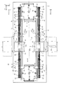
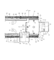
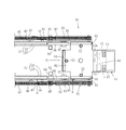
- FIG. 1 is a plan view of a pallet carrying device according to an embodiment of the present invention.
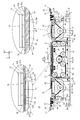
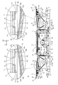
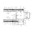
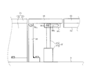
- FIG. 2 is a front view of the pallet conveying device shown in FIG.
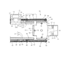
- FIG. 3 is a front view of the pallet conveyance device, and shows a state where the pallet feed assisting unit is lowered by the elevating unit.
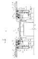
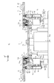
- 4 is a cross-sectional view taken along line IV-IV in FIG.
- FIG. 5 is a plan view of the pallet used in the pallet transport device as seen from the direction V in FIG. 6 is a cross-sectional view taken along the line VI-VI in FIG. 1 and shows a pallet moving unit.
- FIG. 7 is a view corresponding to FIG. 6 showing a state in which the relative movement of the pallet with respect to the short rail is restricted by the pallet locking mechanism.
- FIG. 1 is a plan view of a pallet carrying device according to an embodiment of the present invention.
- FIG. 2 is a front view of the pallet conveying device shown in FIG.
- FIG. 3 is a front view of
- FIG. 8 is a diagram showing a state where the pallet feed assisting portion is lowered by the elevating portion, corresponding to FIG.
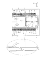
- FIG. 9 is a top view showing a state in which the pallet is conveyed and reaches the end of the first pallet rail.
- FIG. 10 is a top view showing a state in which the pallet is mounted on the short rail from the end of the first pallet rail, corresponding to FIG.
- FIG. 11 is a view corresponding to FIG. 9 showing a state in which the rotating plate is rotated together with the pallet mounted on the short rail.
- FIG. 12 is a top view showing a state in which a pallet mounted on a short rail continuing to the second pallet rail is moved to the second pallet rail, corresponding to FIG. 9.
- FIG. 9 is a top view showing a state in which the pallet is conveyed and reaches the end of the first pallet rail.
- FIG. 10 is a top view showing a state in which the pallet is mounted on the short rail from the end of the first pallet rail, corresponding to
- FIG. 13 is a top view of a modified example in which an auxiliary rail is provided between a pallet rail and a short rail continuous thereto, corresponding to FIG.
- FIG. 14 is a cross-sectional view taken along the line DD of FIG. 13 and shows a state in which the auxiliary rail is raised and the pallet rail and the short rail are continued.
- FIG. 15 is a view corresponding to FIG. 14 showing a state in which the auxiliary rail is lowered and the rotation of the rotating plate is allowed.
- FIG. 16 is a top view of a modified example in which the opposing surfaces of the end portion of the pallet rail and the end portion of the short rail continuous thereto are curved, and are shown corresponding to FIG. 9.
- FIG. 1 and 2 show a pallet transport apparatus 10 according to an embodiment of the present invention.
- three axes X, Y, and Z orthogonal to each other are set.
- the X axis is an axis extending in a substantially horizontal horizontal direction
- the Y axis is an axis extending in a substantially horizontal front-rear direction
- the Z axis is an axis extending in a vertical direction.
- the configuration of the pallet transport apparatus 10 will be described using three axes of X, Y, and Z.
- the pallet conveying device 10 is a conveying device in which the pallet 11 circulates, and conveys the pallet 11 on which the workpiece 6 (FIG. 4) is mounted in a track-shaped track. In addition, the pallet transport device 10 stops the pallet 11 in front of the machine tools 1 to 4 (FIG. 1) provided along the transport path of the pallet 11. The workpiece 6 mounted on the pallet 11 is processed by the machine tools 1 to 4. As described above, the pallet conveying device 10 is used when the workpiece 6 is machined by the machine tools 1 to 4.
- FIG. 1 In FIG. 1, four machine tools 1 to 4 are provided on both sides of the pallet transport device 10. This is an example, and the number of machine tools varies depending on the workpiece 6 that requires machining. The number of pallets 11 is appropriately increased or decreased according to the number of machine tools.
- the pallet transport device 10 in this embodiment includes a first pallet rail 21 and a second pallet rail 31 as a plurality of pallet rails on which pallets are movably mounted.
- the first and second pallet rails 21 and 31 are provided in parallel to each other at a predetermined interval in the horizontal direction (Y-axis direction).
- 1st and 2nd pallet rails 21 and 31 mount pallet 11 so that movement is possible.
- Each of the first and second pallet rails 21 and 31 is provided on the gantry 9 and extends straight in the X-axis direction.
- the pallet 11 is moved and conveyed in a circulating manner along the first and second pallet rails 21 and 31.
- the first pallet rail 21 mounts the pallet 11 in a horizontal state. As shown in detail in FIG. 4, the first pallet rail 21 includes a support plate 22 that is directly fixed on the gantry 9 and a commercially available linear motion guide rail that is fixed to the upper edge of the support plate 22 by screws. 23.
- the pallet 11 includes a linear motion block 12 movably supported on the first and second pallet rails 21, 31, a base 13 screwed to the linear motion block 12, and a locking member provided on the base 13. 14 and.
- the linear motion block 12 is formed so as to straddle the linear motion guide rail 23.
- the linear motion block 12 is sold as a pair with the linear motion guide rail 23.
- the linear motion block 12 includes a roller retainer (not shown).
- the pallet 11 is limited to the first and second pallets while restricting movement in the width direction (Y-axis direction) and tilting with respect to the first and second pallet rails 21 and 31. The resistance generated when moving on the rails 21 and 31 can be remarkably reduced.
- a mounting tool 16 for mounting the workpiece 6 is provided on the upper surface of the base 13.
- the mounting tool 16 is disposed on one side of the base 13.
- the workpiece 6 is fixed to the pedestal 13 by the mounting tool 16.
- the structure of the mounting tool 16 is appropriately changed according to the type of the workpiece 6 to be processed while mounted on the pallet 11.
- the linear motion block 12 is fixed to the other side of the pedestal 13.
- the locking member 14 is provided between the linear motion block 12 and the mounting tool 16 in the base 13.
- the linear motion block 12 is supported so as to be movable so as to straddle the linear motion guide rails 23 in the first and second pallet rails 21 and 31. Therefore, even when one side portion of the pedestal 13 is supported by the first and second pallet rails 21 and 31 via the linear motion block 12, the pallet 11 is in a horizontal state and the first and second pallet rails 21, 31 is movably mounted.
- the machine tools 1 and 2 are installed at a predetermined pitch P, and the machine tools 3 and 4 are installed at a predetermined pitch P.
- the pedestal 13 of the pallet 11 is preferably formed such that the length L in the X-axis direction is the same as or shorter than the pitch P.
- a locking hole 13a into which a lifting rod 72 (FIGS. 6 to 8) in a pallet locking mechanism 71 described later enters is formed on the other side portion of the pedestal 13.
- the locking hole 13a has a diameter slightly larger than the outer diameter of the upper end of the elevating rod 72 so that the upper end of the elevating rod 72 can enter. Details of the locking member 14 will be described later.
- the pallet conveying device 10 is mounted on a first pallet feeding unit 41 that conveys the pallet 11 mounted on the first pallet rail 21 and the second pallet rail 31.
- the first pallet feed unit 41 feeds the pallet 11 along the first pallet rail 21.
- the second pallet feeder 51 sends the pallet 11 along the second pallet rail 31.
- first pallet feed unit 41 Since the first pallet feed unit 41 and the second pallet feed unit 51 have the same structure, the first pallet feed unit 41 will be described below as a representative.
- the first pallet feeder 41 includes a circulation belt 42 provided endlessly along the first pallet rail 21 and a servo motor 43 (FIG. 2) as a circulation mechanism for circulating the circulation belt 42.
- the circulation belt 42 is formed to be engageable with the pallet 11.
- driven pulleys 44 are provided at the four corners of the support plate 22 in the first pallet rail 21.
- the circulation belt 42 is wound around the driven pulleys 44 so as to surround the four driven pulleys 44.
- Servo motor 43 is provided on support plate 22.
- a drive pulley 45 is attached to the rotation shaft 43 a of the servo motor 43.
- the driving pulley 45 and the four driven pulleys 44 are provided on the same plane.
- the first pallet feeder 41 has a pair of turning pulleys 46 that turn the circulation belt 42 so that the circulation belt 42 is wound around the drive pulley 45.
- the pair of turning pulleys 46 are provided in the vicinity of the drive pulley 45 and are pivotally supported by the support plate 22.
- the rotary shaft 43a rotates with the drive pulley 45.
- the circulation belt 42 circulates in a state of surrounding the four driven pulleys 44.
- the circulation belt 42 is a so-called toothed belt. As shown in the enlarged view of FIG. 2, the circulation belt 42 is a belt in which irregularities 42 a and 42 b are alternately formed in the longitudinal direction. The irregularities 42 a and 42 b extend in the width direction of the circulation belt 42. The irregularities 42 a and 42 b are formed so as to be engageable with the irregularities 14 a and 14 b of the pallet 11. The irregularities 14 a and 14 b are formed on the locking member 14 of the pallet 11.
- the locking member 14 is provided below the pedestal 13 in the same manner as the linear motion block 12.
- the locking member 14 engages with the circulation belt 42.
- the irregularities 14a and 14b of the locking member 14 and the irregularities 42a and 42b of the circulation belt 42 are engaged with each other.
- the locking member 14 is lifted and separated from the circulation belt 42, the engagement between the irregularities 42a and 42b of the circulation belt 42 and the irregularities 14a and 14b of the locking member 14 is released.
- the relative movement of the pallet 11 in the X-axis direction with respect to the circulation belt 42 is limited by the engagement between the irregularities 14a and 14b in the pallet 11 and the irregularities 42a and 42b of the circulation belt 42. Accordingly, when the servomotor 43 is driven to circulate the circulation belt 42 engaged with the pallet 11, the pallet 11 moves together with the circulation belt 42. Since the circulation belt 42 is provided along the first pallet rail 21, the pallet 11 is conveyed along the first pallet rail 21. Similarly, since the circulation belt 42 of the second pallet feeding unit 51 is provided along the second pallet rail 31, the pallet 11 is conveyed along the second pallet rail 31.
- the member denoted by reference numeral 47 in FIG. 2 is a support material that supports the circulation belt 42 between the driven pulleys 44.
- the support member 47 prevents the circulation belt 42 from slackening between the driven pulleys 44 and prevents the circulation belt 42 from being separated from the locking member 14.
- a member denoted by reference numeral 48 is a fixture for attaching the support member 47 to the support plate 22.
- pallet moving parts 61 are provided in the vicinity of both ends of the first and second pallet rails 21 and 31, respectively.
- the pallet moving unit 61 moves the pallet 11 from one of the first or second pallet rails 21 and 31 to the other.
- the pallet moving unit 61 moves the pallet 11 from the first pallet rail 21 to the second pallet rail 31 and moves the pallet 11 from the second pallet rail 31 to the first pallet rail 21.
- the pallet moving unit 61 includes a rotating plate 62, one or more short rails 63 provided on the rotating plate 62, and an index unit 64 (FIGS. 6 to 8) that rotates the rotating plate 62.
- the rotating plate 62 is rotatable about a vertical axis on an intermediate line m (shown by a one-dot chain line in FIG. 1) between the first pallet rail 21 and the second pallet rail 31 provided at a predetermined interval.
- the short rail 63 is provided in parallel to the tangent line T on the rotation circumference around the rotation plate 62.
- the pallet moving unit 61 has two pairs of short rails 63.
- the pair of short rails 63 oppose each other on the rotation circumference of the rotating plate 62.
- the index unit 64 has a main body 64a having a rectangular box shape, and a rotating rod 64b protruding upward from a substantially central portion of the upper surface of the main body 64a.
- the main body portion 64a is attached to the gantry 9, and the rotating rod 64b is provided on the main body portion 64a so as to be rotatable about a vertical axis.
- the rotation center O of the rotation rod 64b is located on the intermediate line m (FIG. 1) of the first and second pallet rails 21 and 31.
- the rotating plate 62 is screwed to the upper end of the rotating rod 64b in a horizontal state.
- the rotating plate 62 rotates by a predetermined angle as indicated by a solid line arrow in FIG.
- one or more short rails 63 are provided around the rotating plate 62.
- two pairs of short rails 63 are used, and the pair of short rails 63 face each other on the rotation circumference of the rotating plate 62 in the pallet moving unit 61. That is, a total of four short rails 63 are used.
- the rotating plate 62 is formed in a cross shape in a top view so as to have four projecting ends projecting to the periphery.
- the four short rails 63 are provided at corresponding positions from the rotation center O at the corresponding protruding ends.
- the short rail 63 is provided at four positions every 90 degrees so as to face each other on the rotation circumference of the rotating plate 62.
- the short rail 63 has the same cross-sectional shape as the linear motion guide rail 23 in the first and second pallet rails 21 and 31.
- the length W of the short rail 63 is equal to or longer than the length L of the pallet 11 in the X-axis direction.
- the two short rails 63 are in symmetric positions with the rotation center O as a symmetric point.
- the main body portion 64 a of the index unit 64 is fixed to the gantry 9 so that the two short rails 63 of the two short rails 63 are continuous with the linear motion guide rails 23 of the first and second pallet rails 21 and 31. .
- the short rail 63 when the short rail 63 is rotated 180 degrees around the rotation center O of the rotating plate 62 from the state where the short rail 63 is continuous with the linear motion guide rail 23 in the first pallet rail 21, the short rail 63 becomes the second pallet rail. It continues to the linear motion guide rail 23 at 31.
- the pallet 11 can be moved from the linear motion guide rail 23 to the short rail 63 and mounted on the short rail 63. Moreover, it moves to the linear motion guide rail 23 from the short rail 63, and can be mounted on the linear motion guide rail 23.
- a predetermined gap d is provided between the first pallet rail 21 and the short rail 63.
- a predetermined gap d is provided between the second pallet rail 31 and the short rail 63. The gap d prevents contact between the short rail 63 and the first and second pallet rails 21 and 31 when the rotating plate 62 rotates, and the rotation of the rotating plate 62 is prevented by the first and second pallet rails 21 and 31. Not disturbed.
- the rotating plate 62 is provided with a pallet locking mechanism 71 for each short rail 63.
- the pallet locking mechanism 71 restricts the relative movement of the pallet 11 with respect to the short rail 63 in a state where the pallet 11 is mounted on the short rail 63 provided around the rotating plate 62.
- the pallet locking mechanism 71 includes a lifting rod 72 provided on the rotating plate 62, a coil spring (elastic body) 73 that biases the lifting rod 72, and a first and a second that move the lifting rod 72. Cylinders 74 and 75.
- the lifting rod 72 has an upper end formed so as to be able to enter the locking hole 13 a of the pallet 11 mounted on the short rail 63.
- the coil spring 73 urges the lifting rod 72 in a direction in which the upper end of the lifting rod 72 enters the locking hole 13a.
- the first and second cylinders 74 and 75 move the lifting rod 72 against the urging force of the coil spring 73 in the direction in which the upper end of the lifting rod 72 is detached from the locking hole 13a.
- a through hole 13b is formed in the rotating plate 62, and the lifting rod 72 is provided so as to be movable in the vertical direction through the through hole 13b.
- the lifting rod 72 is provided with a flange 72a. The flange 72a contacts the lower surface of the base 13 around the locking hole 13a from below with the upper end of the lifting rod 72 entering the locking hole 13a (FIGS. 7 and 8).
- the coil spring 73 which is an elastic body, is mounted in a compressed state between the flange 72a and the rotating plate 62.
- the lifting rod 72 is biased upward by the restoring force of the coil spring 73.
- a support 76 is provided on the lower surface of the rotating plate 62 so as to protrude downward.
- a substantially center of the swing piece 77 is pivotally supported at the lower end of the column 76.
- the swing piece 77 extends in the radial direction of the rotating plate 62 and is pivotally supported.
- the outer end of the swing piece 77 is pivotally supported by the lower end of the lifting rod 72.
- the first cylinder 74 is attached to the gantry 9 such that when the short rail 63 is continuous with the first pallet rail 21, the upper end of the retracting rod 74a faces the inner end of the swing piece 77.
- the second cylinder 75 is attached to the gantry 9 such that when the short rail 63 is continuous with the second pallet rail 31, the upper end of the retractable rod 75 a faces the inner end of the swing piece 77.
- the pallet moving unit 61 projects the retracting rod 74 a of the first cylinder 74 to make the lifting rod 72 the urging force of the coil spring 73 as shown in FIG. 6. Move it down. In this state, the lifting rod 72 does not hinder the movement of the pallet 11, so the pallet 11 moves from the first pallet rail 21 to the short rail 63 continuous to the first pallet rail 21 and is mounted on the short rail 63.
- the pallet moving unit 61 immerses the retracting rod 74 a of the first cylinder 74 and moves the lifting rod 72 upward by the biasing force of the coil spring 73.
- the upper end of the elevating rod 72 enters the locking hole 13 a provided in the pallet 11.
- the relative movement of the pallet 11 with respect to the short rail 63 can be restrict
- the pallet moving portion 61 rotates the rotating plate 62 together with the pallet 11. Accordingly, the short rail 63 on which the pallet 11 is mounted can be separated from the first position continuous with the first pallet rail 21 and rotated to the second position continuous with the second pallet rail 31.
- the pallet moving unit 61 projects the retracting rod 75 a of the second cylinder 75 and moves the lifting rod 72 downward again against the biasing force of the coil spring 73.
- the pallet 11 mounted on the short rail 63 is allowed to move, and the pallet 11 can be moved to the second pallet rail 31.
- the pallet carrying device 10 includes a pallet feed assisting portion 81.
- the pallet feed assisting part 81 moves the pallet 11 from the first pallet rail 21 to the short rail 63 continuous with the first pallet rail 21 or the pallet 11 is continued from the short rail 63 to the short rail 63.
- the pallet feed assisting portion 81 moves the pallet 11 from the second pallet rail 31 to the short rail 63 continuous with the second pallet rail 31 or continues the pallet 11 from the short rail 63 to the short rail 63. Move to the second pallet rail 31.
- the pallet feed auxiliary portion 81 is provided in the vicinity of both end portions of the first and second pallet rails 21 and 31. Since these pallet feed auxiliary portions 81 have the same structure, one of them will be described as a representative.
- the pallet feed auxiliary unit 81 in this embodiment includes an auxiliary circulation belt 82 provided continuously to the circulation belt 42, and a servo motor (auxiliary circulation mechanism) 83 (FIG. 2) that circulates the auxiliary circulation belt 82. .
- the auxiliary circulation belt 82 circulates along the end portions of the first and second pallet rails 21, 31 and the short rail 63 continuous to the end portions of the first and second pallet rails 21, 31.
- the auxiliary circulation belt 82 is a so-called toothed belt like the circulation belt 42.
- the auxiliary circulation belt 82 also has irregularities 82a and 82b extending in the width direction.
- the irregularities 82a and 82b are alternately and continuously formed in the longitudinal direction (enlarged view in FIG. 2).
- the irregularities 14a and 14b of the locking member 14 of the pallet 11 are formed to be able to engage with the irregularities 82a and 82b.
- the pallet feed assisting portion 81 has a fulcrum provided at an end near the first and second pallet feed portions 41 and 51, and the other end that rotates up and down around the fulcrum. .
- the pallet feed assisting portion 81 is not limited to this form, and may move up and down horizontally.
- a pivot post 90 is erected on the gantry 9, and an auxiliary plate 91 is pivotally supported on the pivot post 90.
- the pivot column 90 is disposed in the vicinity of both ends of the support plate 22 in the first and second pallet rails 21 and 31.
- the auxiliary plate 91 is continuous with the support plate 22 so that one end of the auxiliary plate 91 is located near the first and second pallet feeding parts 41 and 51, and this one end is pivotally supported by the pivot column 90.
- a guide material 92 is provided horizontally on the upper end of the auxiliary plate 91.
- the guide material 92 extends in the X-axis direction along the end portions of the first and second pallet rails 21, 31 and the short rail 63 continuous to the first and second pallet rails 21, 31.
- the guide member 92 has an auxiliary circulation belt 82 such that the auxiliary circulation belt 82 extends along the end portions of the first and second pallet rails 21 and 31 and the short rail 63 continuous to the first and second pallet rails 21 and 31. Is supported from below.
- the auxiliary plate 91 pivotally supports an auxiliary pulley 93 that turns the auxiliary circulation belt 82 that moves on the upper surface of the guide member 92 and moves in the X-axis direction.
- the auxiliary pulley 93 is disposed on both sides of the guide material 92.
- the auxiliary plate 91 is provided with a servo motor 83 which is an auxiliary circulation mechanism.
- the servo motor 83 circulates the auxiliary circulation belt 82.
- An auxiliary drive pulley 84 is attached to the rotation shaft 83 a of the servo motor 83.
- the auxiliary drive pulley 84 is provided on the same plane as the two auxiliary pulleys 93.
- the auxiliary circulation belt 82 is wound around the auxiliary drive pulley 84 and the auxiliary pulley 93 (FIG. 2).
- the auxiliary circulation belt 82 wound around the auxiliary drive pulley 84 circulates.
- the auxiliary circulation belt 82 moves on the upper surface of the horizontal guide member 92 between the two auxiliary pulleys 93. That is, the auxiliary circulation belt 82 moves along the end portions of the first and second pallet rails 21 and 31 and the short rail 63 that is continuous with the first and second pallet rails 21 and 31.
- the auxiliary circulation belt 82 has irregularities 82a and 82b extending in the width direction and continuously formed in the longitudinal direction. Therefore, when the locking member 14 is overlaid on the auxiliary circulation belt 82, the irregularities 82 a and 82 b of the auxiliary circulation belt 82 engage with the irregularities 14 a and 14 b of the locking member 14.
- the auxiliary circulation belt 82 when the auxiliary circulation belt 82 is circulated at the same speed as the circulation belt 42 engaged with the pallet 11, the pallet 11 moves along the first pallet rail 21 and, as shown by the solid line arrow in FIG. At the end of one pallet rail 21, the belt moves from the circulation belt 42 to the auxiliary circulation belt 82 and engages with the auxiliary circulation belt 82.
- the pallet 11 When the auxiliary circulation belt 82 engaged with the locking member 14 is further circulated, the pallet 11 is connected to the first pallet rail 21 from the end of the first pallet rail 21 as shown in FIG. Move up to. When the auxiliary circulation belt 82 is circulated in the reverse direction, the pallet 11 moves from the short rail 63 to the first pallet rail 21 or the second pallet rail 31.
- the pallet transport device 10 includes a fluid pressure cylinder (elevating part) 95 that elevates and lowers the pallet feeding auxiliary part 81.
- the main body 95b of the fluid pressure cylinder 95 is fixed to the gantry 9 with the retracting rod 95a facing upward.
- the other end of the auxiliary plate 91 is pivotally supported on the upper end of the retracting rod 95a.
- the fluid pressure cylinder 95 is configured such that the auxiliary circulation belt 82 in the auxiliary plate 91 is superposed on the locking member 14 of the pallet 11 mounted on the short rail 63 in a state in which the protruding rod 95a protrudes upward.
- the locking member 14 is provided on the lower surface of the base 13 in the pallet 11. Since the other end of the auxiliary plate 91 is pivotally supported by the other end of the retracting rod 95a, when the retracting rod 95a of the fluid pressure cylinder 95 is immersed in the main body 95b, the pallet feed assisting portion 81 including the auxiliary plate 91 is lowered. As a result, the auxiliary circulation belt 82 in the auxiliary plate 91 is also lowered.
- 3 and 8 show a state in which the pallet 11 has moved to the short rail 63 in a state where the auxiliary circulation belt 82 is superimposed on the locking member 14.
- the irregularities 82a and 82b of the auxiliary circulation belt 82 are separated from the irregularities 14a and 14b in the locking member 14.
- the pallet transport method using the pallet transport device 10 can circulate the pallet 11.
- the pallet conveying method includes a first pallet conveying step for conveying the pallet 11 along the first pallet rail 21 and a first pallet for moving the pallet 11 from the end of the first pallet rail 21 to the second pallet rail 31.
- the pallet 11 is mounted on the first pallet rail 21.
- the pallet 11 is mounted on the second pallet rail 31.
- each step when the pallet 11 circulates in a counterclockwise orbit in the top view in FIG. 1 will be described below.
- a workpiece 6 that requires predetermined processing is mounted.
- the workpiece 6 is mounted on the pallet 11 mounted on the first pallet rail 21
- the end of the linear motion guide rail 23 in the first pallet rail 21 is inserted into the linear motion block 12 of the pallet 11, and the linear motion block 12 is moved to the linear motion guide rail 23. To be installed.
- the irregularities 14 a and 14 b on the pallet 11 engage with the irregularities 42 a and 42 b of the circulation belt 42 provided along the first pallet rail 21.
- the pallet 11 can be transported along the first pallet rail 21 by driving the servo motor 43 as a driving mechanism to circulate the circulation belt 42.
- the pallet 11 is conveyed until it faces each of the machine tools 1 and 2 provided along the first pallet rail 21.
- the servo motor 43 is stopped.
- the workpiece 6 mounted on the pallet 11 is processed by each of the machine tools 1 and 2.
- First pallet moving process In this step, the pallet 11 is moved to the second pallet rail 31 from the end of the first pallet rail 21. This movement is performed by a pallet moving unit 61 provided in the vicinity of one end of the first and second pallet rails 21 and 31.
- an auxiliary circulation belt 82 is provided continuously to the circulation belt 42.
- the pallet 11 moves along the first pallet rail 21 in the above-described first pallet conveying step and immediately before reaching the end of the first pallet rail 21, as shown by the solid line arrow in FIG. It moves to an auxiliary circulation belt 82 that is continuous with the circulation belt 42.
- the pallet 11 is engaged with the auxiliary circulation belt 82.
- the auxiliary circulation belt 82 By circulating the auxiliary circulation belt 82 at the same speed as the circulation belt 42, the pallet 11 reaches the end of the first pallet rail 21.
- the auxiliary circulation belt 82 that circulates along the end portion of the first pallet rail 21 and the short rail 63 that continues to the end portion of the first pallet rail 21 continues to the circulation belt 42.
- the pallet 11 engaged with the auxiliary circulation belt 82 can be retained at the end of the first pallet rail 21 regardless of the circulation of the circulation belt 42.
- the circulation belt 42 is circulated, the pallet 11 different from the pallet 11 held at the end of the first pallet rail 21 is moved along the first pallet rail 21 regardless of the circulation of the auxiliary circulation belt 82. Can be moved. That is, by providing the auxiliary circulation belt 82 continuously to the circulation belt 42, the pallet 11 that moves in the first pallet moving step and the pallet 11 that is different from the pallet 11 can be moved along the first pallet rail 21.
- the rotating plate 62 is rotated by the index unit 64 in the pallet moving unit 61 (FIG. 6), and the short rail 63 is made continuous with the first pallet rail 21.
- the auxiliary circulation belt 82 is circulated to move the pallet 11 from the end of the first pallet rail 21 to the short rail 63.
- the pallet 11 is mounted on the short rail 63.
- the retracting rod 74a of the first cylinder 74 is projected from the main body 74b.
- the elevating rod 72 facing the short rail 63 continuous with the first pallet rail 21 moves downward against the urging force of the coil spring 73.
- the pallet 11 is moved from the first pallet rail 21 to the short rail 63 continuous to the first pallet rail 21, and the pallet 11 is mounted on the short rail 63.
- the retracting rod 74a of the first cylinder 74 is immersed in the main body 74b.
- the elevating rod 72 moves upward by the urging force of the coil spring 73, and the upper end of the elevating rod 72 enters the locking hole 13 a provided in the pallet 11. Thereby, when rotating the rotating plate 62 and moving the pallet 11, it is possible to prevent the pallet 11 from moving relative to the short rail 63.
- the retracting rod 95a of the fluid pressure cylinder 95 is immersed in the main body 95b in this state. Since the other end of the auxiliary plate 91 is pivotally supported at the upper end of the retracting rod 95a, the auxiliary plate 91 is lowered. As a result, the engagement between the pallet 11 and the auxiliary circulation belt 82 is released.
- the index unit 64 rotates the rotating plate 62 as shown in FIG.
- the short rail 63 on which the pallet 11 is mounted moves from a first position continuous with the first pallet rail 21 and rotates to a second position continuous with the second pallet rail 31.
- the next short rail 63 is continued to the first pallet rail 21 by rotating the rotating plate 62 by 90 degrees. For this reason, when the rotating plate 62 is rotated by 90 degrees, the short rail 63 continuous to the first pallet rail 21 remains away from the first position, and the pallet 11 mounted on the short rail 63 is the first.
- the second pallet rail 31 moves to a second position.
- the rotation angle of the rotation plate 62 required in the pallet moving process is reduced. Therefore, the pallet 11 can be moved quickly.
- the retracting rod 95 a of the fluid pressure cylinder 95 protrudes upward and descends.
- the other end of the auxiliary plate 91 that has been raised is raised.
- the auxiliary circulation belt 82 is superimposed on the locking member 14 in the pallet 11, and the irregularities 82 a and 82 b of the auxiliary circulation belt 82 are engaged with the irregularities 14 a and 14 b in the locking member 14 again.
- the program is set in advance so that the projections and depressions 14a and 14b of the locking member 14 of the pallet 11 and the projections and depressions 82a and 82b of the auxiliary circulation belt 82 are securely engaged.
- the rotation angle of the servo motor 83 is controlled.
- the auxiliary circulation belt 82 located near the end of the second pallet rail 31 and engaged with the pallet 11 is circulated, and the pallet 11 is moved together with the auxiliary circulation belt 82.
- the pallet 11 moves from the short rail 63 to the second pallet rail 31.
- the pallet 11 is moved from the end of the first pallet rail 21 to the second pallet rail 31.
- ⁇ Second pallet transport process> the pallet 11 mounted on the second pallet rail 31 is transported.
- the pallet 11 moves from the short rail 63 to the second pallet rail 31 as shown in FIG. Specifically, the pallet 11 moves to the end of the second pallet rail 31 in a state of being engaged with the auxiliary circulation belt 82 provided along the end of the second pallet rail 31.
- the pallet 11 mounted on the second pallet rail 31 is transported.
- the auxiliary circulation belt 82 is circulated at the same speed as the circulation belt 42 provided along the second pallet rail 31 and continuing to the auxiliary circulation belt 82.
- the pallet 11 starts to move in the opposite direction from the end of the second pallet rail 31 and is separated from the end of the second pallet rail 31 as shown in FIG. As a result, the pallet 11 moves away from the auxiliary circulation belt 82 and engages with the circulation belt 42. By circulating the circulation belt 42, the pallet 11 can be conveyed along the second pallet rail 31.
- the pallet 11 is transported along the second pallet rail 31 until the pallet 11 faces each of the machine tools 3 and 4 provided along the second pallet rail 31.
- the servo motor 43 is stopped.
- the workpiece 6 mounted on the pallet 11 is processed by each of the machine tools 3 and 4.
- the auxiliary circulation belt 82 that circulates along the end of the second pallet rail 31 and the short rail 63 that continues to the end of the second pallet rail 31 is provided continuously to the circulation belt 42. For this reason, by circulating the circulation belt 42 and the auxiliary circulation belt 82 separately, it is possible to maintain the pallet 11 at the end of the second pallet rail 31 without overlapping the pallet 11 with the circulation belt 42. Specifically, as shown in FIG. 11, the circulation of the auxiliary circulation belt 82 causes the pallet 11 to move from the short rail 63 to the end of the second pallet rail 31 and then circulate before the pallet 11 reaches the circulation belt 42. To stop. Since the pallet 11 does not engage with the circulation belt 42, the pallet 11 can be maintained at the end of the second pallet rail 31 regardless of the circulation of the circulation belt 42.
- the pallet 11 engaged with the circulation belt 42 is conveyed on the second pallet rail 31 by the circulation of the circulation belt 42.
- the circulation belt 42 mounted on the second pallet rail 31 is moved without moving the pallet 11 mounted on the end of the second pallet rail 31 and engaged with the auxiliary circulation belt 82 but not engaged with the circulation belt 42.
- the pallet 11 engaged with the can be moved.
- the auxiliary circulation belt 82 is circulated and the pallet 11 engaged with the auxiliary circulation belt 82. Is moved and engaged with the circulation belt 42. Thereby, the plurality of pallets 11 can be conveyed on the second pallet rail 31 at a predetermined pitch.
- each pallet 11 can be transported by one track-shaped track in the counterclockwise direction.
- the machine tools 1 to 4 are operated in a state where the operation of the pallet conveying device 10 is stopped, and each workpiece 6 (not shown) placed on each pallet 11 is operated. Then, predetermined various processes are performed in parallel. When each of the machine tools 1 to 4 is operated, the workpiece 6 is carried into or out of any pallet 11.
- the auxiliary circulation belt 82 engages with the pallet 11 mounted on the short rail 63. For this reason, the pallet 11 can be reliably guided to the short rail 63 by the auxiliary circulation belt 82.
- the pallet transport device 10 includes a fluid pressure cylinder (elevating unit) 95 that elevates and lowers the pallet feed auxiliary unit 81.
- a fluid pressure cylinder (elevating unit) 95 that elevates and lowers the pallet feed auxiliary unit 81.
- the engagement between the pallet 11 mounted on the short rail 63 and the pallet feed assisting portion 81 can be released.
- the rotating plate 62 together with the short rail 63 in a state where the engagement is released the pallet 11 is reliably semicircularly formed from the end of the first pallet rail 21 to the end of the second pallet rail 31. It can be moved in orbit.
- the pallet feed assisting portion 81 is raised, the auxiliary circulation belt 82 is engaged again with the pallet 11 mounted on the short rail 63. Therefore, the pallet 11 can be reliably moved to the other pallet rail 31 from the short rail 63 that is moved together with the pallet 11 by a semicircular activation and connected to the edge of the other pallet rail 31.
- the pallet 11 can be reliably circulated in the track-shaped track.
- the engagement of the pallet 11 and the pallet feed assisting portion 81 and the release thereof can also be performed by raising and lowering the pallet 11.
- the weight of the pallet 11 is relatively large, and raising and lowering the pallet 11 causes power consumption.
- the workpiece 6 also moves up and down as the pallet 11 moves up and down.
- the mounting of the work 6 by the mounting tool 16 needs to be able to withstand the elevation, and the structure of the mounting tool 16 on which the work 6 is mounted may be complicated.
- the pallet feed assisting portion 81 since the pallet feed assisting portion 81 is moved up and down, the pallet 11 and the pallet feed assisting portion 81 can be engaged and released with less power. Moreover, it is not necessary to consider the raising / lowering of the workpiece
- the workpiece 6 is mounted on one side of the pedestal 13, and the linear motion block 12 is fixed to the other side of the pedestal 13. Since the first pallet rail 21 and the second pallet rail 31 support the linear motion block 12, one side of the base 13 on which the workpiece 6 is mounted is always directed to the outside of the track-shaped track, and the pallet 11 is tracked. It can be circulated in a shape orbit. For this reason, it becomes possible to install the machine tools 1 to 4 for the workpiece 6 on both sides of the pallet conveying device 10.
- the pallet 11 is engaged with the endless circulation belt 42 and is conveyed along the first pallet rail 21 and the second pallet rail 31.
- the interval between the plurality of pallets 11 conveyed along the first pallet rail 21 or the second pallet rail 31 can be changed. That is, the transport pitch between the pallet 11 transported first and the pallet 11 transported later can be easily changed.
- the first pallet rail 21 and the short continuation to the first pallet rail 21 are used.
- a predetermined gap d (FIG. 1) is provided between the rail 63.
- the gap d is preferably as small as possible in order to smoothly move the pallet 11 between the first pallet rail 21 and the short rail 63 continuous to the first pallet rail 21.
- an auxiliary rail 96 is interposed between them as shown in FIG. It may be provided.
- the auxiliary rail 96 is provided along the pallet feed auxiliary portion 81 so as to be continuous with the end portions of the first and second pallet rails 21 and 31. More specifically, the auxiliary rail 96 is provided on the same straight line of the first and second pallet rails 21 and 31.
- the cross-sectional shape of the auxiliary rail 96 is substantially the same as that of the linear motion guide rail 23 and the short rail 63 in the first and second pallet rails 21 and 31.
- the length of the auxiliary rail 96 is the gap between the first pallet rail 21 and the short rail 63 that continues to the first pallet rail 21, or the short rail that continues to the second pallet rail 31 and the second pallet rail 31. 63 is substantially equal to the gap between
- the pallet transport device 10 further requires a fluid pressure cylinder (auxiliary rail elevating unit) 97 that raises and lowers the auxiliary rail 96.
- the fluid pressure cylinder 97 moves the auxiliary rail 96 up and down between a first position where the auxiliary rail 96 continues to the end portions of the first and second pallet rails 21 and 31 and a second position below the first position.
- the auxiliary rail 96 in the present embodiment has a fulcrum 96 a at the end near the first and second pallet rails 21, 31, and the short rail 63 with the fulcrum 96 a as a rotation axis. The other end that faces is raised and lowered.
- the fulcrum 96a of the auxiliary rail 96 is pivotally supported together with one end of the auxiliary plate 91 on the upper end of the pivot column 90 that pivotally supports one end of the auxiliary plate 91 (FIG. 13).
- the main body 97b of the fluid pressure cylinder 97 is fixed to the gantry 9 with the retracting rod 97a facing upward.
- the other end of the auxiliary rail 96 is pivotally supported at the upper end of the retracting rod 97a.
- the auxiliary rail 96 is a linear motion guide rail 23 in the first and second pallet rails 21 and 31 and a short rail continuous with the auxiliary rail 96 in a state where the protruding and retracting rod 97a protrudes upward. It is comprised so that the clearance gap between 63 may be block
- a locking plate 96c is attached to the lower surface of the other end of the auxiliary rail 96.
- the locking plate 96c has a long hole 96b extending in the longitudinal direction.
- the upper end of the retracting rod 97a of the fluid pressure cylinder 97 is pivotally supported through the pin 96d in the long hole 96b.
- the pin 96d moves inside the elongated hole 96b and lowers the other end of the auxiliary rail 96.
- the auxiliary rail 96 closes the gap between the linear motion guide rail 23 in the first and second pallet rails 21 and 31 and the short rail 63 continuous thereto.
- the auxiliary rail 96 moves the pallet 11 from the first or second pallet rail 21, 31 to the short rail 63 continuous to the first or second pallet rail 21, 31, or from the short rail 63 to the first or second pallet. It becomes easy to move to the rails 21 and 31.
- the pallet 11 can be surely secured from the first or second pallet rail 21, 31 to the short rail 63 or from the short rail 63 to the first or second pallet rail 21, 31.
- the rotary plate 62 can also be freely rotated.
- the clearance d As a method for minimizing (see FIG. 1) as much as possible, as shown in FIG. 16, the opposing surfaces of the end portions of the first pallet rail 21 and the second pallet rail 31 and the end portion of the short rail 63 continuous thereto are arranged. It is also possible to process a curved surface. In this case, the curvature R of the curved surface processing is desirably finished to be equal to the curvature of the rotation circle of the rotating plate 62.
- the end of the short rail 63 is processed to have a curved surface equivalent to the curvature R of the rotation circle of the rotating plate 62, and the ends of the first pallet rail 21 and the second pallet rail 31 facing the ends. It is possible to eliminate a gap in the X-axis direction between the first pallet rail 21 or the second pallet rail 31 and the continuous short rail 63 by processing the curved surface as well. In spite of the absence of such a gap, the end rails are curved in the same manner as the curvature R of the rotation circle of the rotating plate 62, so that the short rail 63 is moved to the pallet rail 21, when the rotating plate 62 is rotated. Interference with 31 is avoided, and the rotating plate 62 can be freely rotated.
- the first pallet rail 21 and the first pallet rail 21 provided in parallel with each other at a predetermined interval in the horizontal direction are used as the plurality of pallet rails on which the pallet in the circulation type pallet transport device is movably mounted.
- the case where the two pallet rails 31 are provided has been described.
- the short rails in this case are not limited to the above-described paired pairs, and a plurality of short rails may be provided in parallel to the tangent line T (FIG. 1) on the rotation circumference of the pallet moving unit.
- the first and second pallet feeding units 41 and 51 include the circulation belt 42 and the circulation mechanism (servo motor 43) that circulates the circulation belt 42.
- the first and second pallet feeding units 41 and 51 are not limited to this form, and may have other configurations as long as the pallet 11 can be conveyed along the first and second pallet rails 21 and 31.
- two pairs of short rails 63 each having a pair opposed to each other on the rotation circumference of the rotating plate 62 in the pallet moving unit 61 are provided.
- the short rail 63 composed of a pair may be one set, or three, four, five or more sets may be provided. As the number of pairs of the short rails 63 increases, the rotation angle of the rotating plate 62 in the pallet moving unit 61 when moving the pallet 11 can be reduced.
- the rotating plate 62 in the pallet moving unit 61 is formed in a cross shape when viewed from above.
- the rotating plate 62 may have a disk shape, a polygonal shape, or a rod shape as viewed from above, and one or more short rails 63 are parallel to the tangent line T on the rotating circumference of the pallet moving unit 61. If it is provided, the shape of the rotating plate 62 is not concerned.
- the pallet 11 circulates in the counterclockwise direction. It is also possible to transport each pallet 11 not in the counterclockwise direction but in the clockwise direction.
- the mounting tool 16 for mounting the workpiece 6 is provided on the upper surface of one side portion of the base 13 .
- a through hole may be formed in the pedestal 13
- a mounting tool 16 may be provided in the through hole
- the workpiece 6 may be mounted through the pedestal 13 through the through hole.
- the pallet transport device includes a plurality of pallet rails on which pallets are movably mounted, a pallet feed unit that transports the pallets along the pallet rails, and a plurality of pallet rails provided at the end of the plurality of pallet rails.
- a pallet moving unit that horizontally rotates and moves the pallet mounted on any one of the pallet rails to another pallet rail.
- the pallet transport device includes one or more short rails provided around the pallet moving unit, and a pallet feed assist that moves the pallet from the pallet rail to the short rail, or from the short rail to the pallet rail. And an elevating part that lowers and raises the pallet feed assisting part. Horizontal rotation of the pallet moving part is allowed by lowering the pallet feed auxiliary part.
- the plurality of pallet rails are provided in parallel with each other at a predetermined interval in the horizontal direction, and the short rails are provided with a plurality of pairs that are opposed to each other on the rotation circumference of the pallet moving unit.
- the pallet feed auxiliary portion includes an end of the pallet rail and an auxiliary circulation belt that is provided endlessly along the short rail continuous with the pallet rail and circulates, and the auxiliary circulation belt extends in the width direction and extends in the longitudinal direction.
- the unevenness of the pallet becomes uneven on the auxiliary circulation belt. It is preferable that the pallet is moved by engagement and circulation of the auxiliary circulation belt, and the unevenness of the auxiliary circulation belt is separated from the unevenness of the pallet when the pallet feed auxiliary portion is lowered.
- the short rail is preferably provided in parallel to the tangent on the rotation circumference of the pallet moving part, and the pallet feed auxiliary part has a fulcrum at the end close to the pallet feed part, and the fulcrum is a rotation axis.
- the other end may be raised and lowered.
- the pallet transport device has an auxiliary rail provided along the pallet feed auxiliary portion on the same straight line of the pallet rail so as to be continuous with an end portion of the pallet rail, and an auxiliary rail continuous with the end portion of the pallet rail.
- An auxiliary rail elevating part that elevates and lowers between a first position and a second position below the first position can be further provided.
- the auxiliary rail may have a fulcrum at the end near the pallet rail, and the other end may move up and down with the fulcrum as the rotation axis.
- the pallet conveying apparatus of this embodiment moves one or two or more short rails provided around the pallet moving unit and the pallet from the pallet rail to the short rail, or from the short rail to the pallet rail.
- a pallet feed assisting portion and an elevating portion for lowering and raising the pallet feed assisting portion are provided, and horizontal rotation of the pallet moving portion is allowed by lowering the pallet feed assisting portion.
- the pallet feed assisting portion engages with the pallet mounted on the short rail, the pallet feed assisting portion is lowered to allow the rotation of the rotating plate, thereby engaging the pallet and the pallet feed assisting portion. It can be canceled.
- the pallet on the short rail can be moved along the semicircular track to the other pallet rail. If a pallet locking mechanism is provided during this movement, the relative movement of the pallet with respect to the short rail can be restricted.
- the pallet feed auxiliary part is raised, the pallet feed auxiliary part is engaged again with the pallet mounted on the short rail. Therefore, the pallet can be moved again to the other pallet rail from the short rail connected to the edge of the other pallet rail by moving in a semicircular orbit together with the pallet. As a result, the pallet can be reliably circulated in the track-shaped track.
Abstract
Description
この工程では、第一パレットレール21に搭載されたパレット11を搬送する。
この工程では、第一パレットレール21の端部からパレット11を第二パレットレール31に移動させる。この移動は第一及び第二パレットレール21,31の一方の端部近傍に設けられたパレット移動部61により行われる。
この工程では、第二パレットレール31に搭載されたパレット11を搬送する。前述の第一パレット移動工程では、図11に示すように、パレット11は、短レール63から第二パレットレール31に移動する。具体的には、パレット11は、第二パレットレール31の端部に沿って設けられた補助循環ベルト82に係合した状態で、第二パレットレール31の端部に移動する。
この工程では、第二パレットレール31の端部に達したパレット11を第一パレットレール21に移動させる。この移動は第一パレットレール21及び第二パレットレール31の他方の端部に設けられたパレット移動部61により行われる。その具体的な移動の手順は、先の第一パレット移動工程と同一であるので、繰り返しての説明を省略する。
Claims (8)
- パレット搬送装置であって、
パレットを移動可能に搭載する複数のパレットレールと、
前記パレットを前記パレットレールに沿って搬送するパレット送り部と、
前記複数のパレットレールの端部に設けられ、前記複数のパレットレールのいずれか一つのパレットレールに搭載された前記パレットを他のパレットレールに水平回転して移動させるパレット移動部と、
前記パレット移動部の周囲に設けられた1又は2以上の短レールと、
前記パレットを前記パレットレールから前記短レールに移動、又は前記パレットを前記短レールから前記パレットレールに移動させるパレット送り補助部と、
前記パレット送り補助部を下降及び上昇させる昇降部と、を備え、
前記パレット移動部の水平回転は前記パレット送り補助部を下降させて許容される、
パレット搬送装置。 - 請求項1に記載のパレット搬送装置であって、
前記複数のパレットレールは、水平方向に所定の間隔を開けて互いに平行に設けられ、前記短レールは、前記パレット移動部の回転円周上で対向して一対で設けられ、前記一対の短レールが複数設けられる、
パレット搬送装置。 - 請求項1に記載のパレット搬送装置であって、
前記複数のパレットレールは、水平方向に所定の間隔を開けて互いに直角又は所定の角度で設けられ、前記短レールは、前記パレット移動部の回転円周上に複数設けられる、
パレット搬送装置。 - 請求項1に記載のパレット搬送装置であって、
前記パレット送り補助部は、前記パレットレールの端部、及び前記パレットレールの端部に連続する短レールに沿って、無端で設けられて循環する補助循環ベルトを備え、
前記補助循環ベルトは、幅方向に延び長手方向に交互に連続して形成される凹凸を有し、
前記補助循環ベルトの前記凹凸に係合可能な凹凸が前記パレットの下面に形成され、
前記パレット送り補助部が上昇すると前記補助循環ベルトの前記凹凸に前記パレットの前記凹凸が係合して前記補助循環ベルトの循環により前記パレットを移動させ、
前記パレット送り補助部が下降すると前記補助循環ベルトの前記凹凸が前記パレットの前記凹凸から離間する、
パレット搬送装置。 - 請求項1記載のパレット搬送装置であって、
前記短レールは、前記パレット移動部の回転円周上の接線に平行して設けられる、
パレット搬送装置。 - 請求項1に記載のパレット搬送装置であって、
前記パレット送り補助部は、前記パレット送り部に近い側の端部に支点を有し、前記支点を回転軸として他端が昇降する、
パレット搬送装置。 - 請求項1記載のパレット搬送装置であって、
前記パレットレールの端部に連続するように前記パレットレールの同一直線上に前記パレット送り補助部に沿って設けられた補助レールと、
前記補助レールを、前記パレットレールの端部に連続する第一位置と、前記第一位置より下方の第二位置の間で昇降させる補助レール昇降部と、を更に備えた、
パレット搬送装置。 - 請求項7に記載のパレット搬送装置であって、
前記補助レールは前記パレットレールに近い側の端部に支点を有し、前記支点を回転軸として他端が昇降する、
パレット搬送装置。
Priority Applications (4)
| Application Number | Priority Date | Filing Date | Title |
|---|---|---|---|
| US15/757,857 US10399788B2 (en) | 2015-09-08 | 2016-08-31 | Pallet transport device |
| KR1020187004807A KR102017097B1 (ko) | 2015-09-08 | 2016-08-31 | 팔레트 반송 장치 |
| CN201680048911.9A CN107921596B (zh) | 2015-09-08 | 2016-08-31 | 托盘搬送装置 |
| EP16844258.0A EP3348348B1 (en) | 2015-09-08 | 2016-08-31 | Pallet transport device |
Applications Claiming Priority (4)
| Application Number | Priority Date | Filing Date | Title |
|---|---|---|---|
| JP2015176314 | 2015-09-08 | ||
| JP2015-176314 | 2015-09-08 | ||
| JP2016-157247 | 2016-08-10 | ||
| JP2016157247A JP6615067B2 (ja) | 2015-09-08 | 2016-08-10 | パレット搬送装置 |
Publications (1)
| Publication Number | Publication Date |
|---|---|
| WO2017043397A1 true WO2017043397A1 (ja) | 2017-03-16 |
Family
ID=58239712
Family Applications (1)
| Application Number | Title | Priority Date | Filing Date |
|---|---|---|---|
| PCT/JP2016/075545 WO2017043397A1 (ja) | 2015-09-08 | 2016-08-31 | パレット搬送装置 |
Country Status (1)
| Country | Link |
|---|---|
| WO (1) | WO2017043397A1 (ja) |
Cited By (2)
| Publication number | Priority date | Publication date | Assignee | Title |
|---|---|---|---|---|
| US20190367291A1 (en) * | 2018-05-29 | 2019-12-05 | The Procter & Gamble Company | Apparatus That Controls Motion of Proximate Independent Movers Along a Path |
| EP3620410A1 (en) * | 2018-05-29 | 2020-03-11 | The Procter & Gamble Company | Method of independently controlling movers along a path |
Citations (6)
| Publication number | Priority date | Publication date | Assignee | Title |
|---|---|---|---|---|
| JPH0537435U (ja) * | 1991-09-04 | 1993-05-21 | 村田機械株式会社 | ワークフイーダ |
| JPH0544440U (ja) * | 1991-11-22 | 1993-06-15 | オークマ株式会社 | ワークテーブル |
| JP2007021629A (ja) * | 2005-07-14 | 2007-02-01 | Nittoku Eng Co Ltd | パレット搬送方法及び装置 |
| US20070028795A1 (en) * | 2005-07-20 | 2007-02-08 | Marsilli & Co. S.P.A. | Automatic production line for processing and assembling components for industries in general |
| JP2011093032A (ja) * | 2009-10-29 | 2011-05-12 | Nittoku Eng Co Ltd | パレット搬送装置及びパレット搬送方法 |
| JP2016117117A (ja) * | 2014-12-19 | 2016-06-30 | 日特エンジニアリング株式会社 | 循環式パレット搬送装置 |
-
2016
- 2016-08-31 WO PCT/JP2016/075545 patent/WO2017043397A1/ja active Application Filing
Patent Citations (6)
| Publication number | Priority date | Publication date | Assignee | Title |
|---|---|---|---|---|
| JPH0537435U (ja) * | 1991-09-04 | 1993-05-21 | 村田機械株式会社 | ワークフイーダ |
| JPH0544440U (ja) * | 1991-11-22 | 1993-06-15 | オークマ株式会社 | ワークテーブル |
| JP2007021629A (ja) * | 2005-07-14 | 2007-02-01 | Nittoku Eng Co Ltd | パレット搬送方法及び装置 |
| US20070028795A1 (en) * | 2005-07-20 | 2007-02-08 | Marsilli & Co. S.P.A. | Automatic production line for processing and assembling components for industries in general |
| JP2011093032A (ja) * | 2009-10-29 | 2011-05-12 | Nittoku Eng Co Ltd | パレット搬送装置及びパレット搬送方法 |
| JP2016117117A (ja) * | 2014-12-19 | 2016-06-30 | 日特エンジニアリング株式会社 | 循環式パレット搬送装置 |
Cited By (5)
| Publication number | Priority date | Publication date | Assignee | Title |
|---|---|---|---|---|
| US20190367291A1 (en) * | 2018-05-29 | 2019-12-05 | The Procter & Gamble Company | Apparatus That Controls Motion of Proximate Independent Movers Along a Path |
| EP3578484A1 (en) * | 2018-05-29 | 2019-12-11 | The Procter & Gamble Company | Apparatus that controls motion of proximate independent movers along a path |
| EP3620410A1 (en) * | 2018-05-29 | 2020-03-11 | The Procter & Gamble Company | Method of independently controlling movers along a path |
| US11479415B2 (en) | 2018-05-29 | 2022-10-25 | The Procter & Gamble Company | Method of independently controlling motion of movers along a path |
| US11505410B2 (en) | 2018-05-29 | 2022-11-22 | The Procter & Gamble Company | Method of independently controlling motion of movers along a path |
Similar Documents
| Publication | Publication Date | Title |
|---|---|---|
| JP6615067B2 (ja) | パレット搬送装置 | |
| TWI680929B (zh) | 托板搬送裝置 | |
| JP4855802B2 (ja) | 長尺形材加工装置及び方法 | |
| TWI722197B (zh) | 托板搬送裝置 | |
| JP6112713B2 (ja) | パレット搬送装置及びパレット搬送方法 | |
| JP6452433B2 (ja) | 循環式パレット搬送装置 | |
| JP6655854B2 (ja) | パレット搬送装置 | |
| JP6460826B2 (ja) | パレット搬送装置 | |
| JP2016150391A (ja) | ワーク搬送用パレット | |
| WO2018135308A1 (ja) | パレット搬送装置及びパレット搬送方法 | |
| JP6650651B2 (ja) | パレット搬送装置及びそれを用いたパレット搬送方法 | |
| JP2020199601A (ja) | 搬送装置および工作機械 | |
| WO2017047394A1 (ja) | ガントリ型搬送装置および加工ライン | |
| WO2017043397A1 (ja) | パレット搬送装置 | |
| WO2017073305A1 (ja) | パレット搬送装置 | |
| JP2021016919A (ja) | パレット搬送装置及びパレット搬送静止方法 | |
| JP6452431B2 (ja) | パレット搬送装置 | |
| JP6705703B2 (ja) | パレット搬送装置 | |
| JP2022052940A (ja) | パレット搬送装置及びパレット搬送方法 |
Legal Events
| Date | Code | Title | Description |
|---|---|---|---|
| 121 | Ep: the epo has been informed by wipo that ep was designated in this application |
Ref document number: 16844258 Country of ref document: EP Kind code of ref document: A1 |
|
| ENP | Entry into the national phase |
Ref document number: 20187004807 Country of ref document: KR Kind code of ref document: A |
|
| WWE | Wipo information: entry into national phase |
Ref document number: 15757857 Country of ref document: US |
|
| NENP | Non-entry into the national phase |
Ref country code: DE |
|
| WWE | Wipo information: entry into national phase |
Ref document number: 2016844258 Country of ref document: EP |