WO2017043345A1 - 電磁石装置及びこれを用いた電磁継電器 - Google Patents
電磁石装置及びこれを用いた電磁継電器 Download PDFInfo
- Publication number
- WO2017043345A1 WO2017043345A1 PCT/JP2016/075079 JP2016075079W WO2017043345A1 WO 2017043345 A1 WO2017043345 A1 WO 2017043345A1 JP 2016075079 W JP2016075079 W JP 2016075079W WO 2017043345 A1 WO2017043345 A1 WO 2017043345A1
- Authority
- WO
- WIPO (PCT)
- Prior art keywords
- coil
- secondary coil
- electromagnet device
- electromagnetic relay
- cylindrical body
- Prior art date
- Legal status (The legal status is an assumption and is not a legal conclusion. Google has not performed a legal analysis and makes no representation as to the accuracy of the status listed.)
- Ceased
Links
Images





Classifications
-
- H—ELECTRICITY
- H01—ELECTRIC ELEMENTS
- H01H—ELECTRIC SWITCHES; RELAYS; SELECTORS; EMERGENCY PROTECTIVE DEVICES
- H01H50/00—Details of electromagnetic relays
- H01H50/44—Magnetic coils or windings
-
- H—ELECTRICITY
- H01—ELECTRIC ELEMENTS
- H01H—ELECTRIC SWITCHES; RELAYS; SELECTORS; EMERGENCY PROTECTIVE DEVICES
- H01H50/00—Details of electromagnetic relays
- H01H50/02—Bases; Casings; Covers
- H01H50/04—Mounting complete relay or separate parts of relay on a base or inside a case
-
- H—ELECTRICITY
- H01—ELECTRIC ELEMENTS
- H01H—ELECTRIC SWITCHES; RELAYS; SELECTORS; EMERGENCY PROTECTIVE DEVICES
- H01H50/00—Details of electromagnetic relays
- H01H50/02—Bases; Casings; Covers
- H01H50/06—Bases; Casings; Covers having windows; Transparent cases or covers
-
- H—ELECTRICITY
- H01—ELECTRIC ELEMENTS
- H01H—ELECTRIC SWITCHES; RELAYS; SELECTORS; EMERGENCY PROTECTIVE DEVICES
- H01H50/00—Details of electromagnetic relays
- H01H50/08—Indicators; Distinguishing marks
-
- H—ELECTRICITY
- H01—ELECTRIC ELEMENTS
- H01H—ELECTRIC SWITCHES; RELAYS; SELECTORS; EMERGENCY PROTECTIVE DEVICES
- H01H50/00—Details of electromagnetic relays
- H01H50/16—Magnetic circuit arrangements
- H01H50/36—Stationary parts of magnetic circuit, e.g. yoke
-
- H—ELECTRICITY
- H01—ELECTRIC ELEMENTS
- H01H—ELECTRIC SWITCHES; RELAYS; SELECTORS; EMERGENCY PROTECTIVE DEVICES
- H01H9/00—Details of switching devices, not covered by groups H01H1/00 - H01H7/00
- H01H9/16—Indicators for switching condition, e.g. "on" or "off"
- H01H9/161—Indicators for switching condition, e.g. "on" or "off" comprising light emitting elements
-
- H—ELECTRICITY
- H01—ELECTRIC ELEMENTS
- H01H—ELECTRIC SWITCHES; RELAYS; SELECTORS; EMERGENCY PROTECTIVE DEVICES
- H01H50/00—Details of electromagnetic relays
- H01H50/44—Magnetic coils or windings
- H01H2050/446—Details of the insulating support of the coil, e.g. spool, bobbin, former
Definitions
- the present invention relates to an electromagnet device, and more particularly to an electromagnet device in which a coil is double-wound and incorporated in an electromagnetic relay, and an electromagnetic relay using the same.
- FIG. 8 of Patent Document 1 there is a bobbin finished body 111 formed by winding a coil 112 around a bobbin 113 in two layers.
- FIG. 8 discloses an electromagnetic relay in which the bobbin complete body 111 is incorporated in a base 116.
- an object of the present invention is to provide a small and highly productive electromagnet device and an electromagnetic relay using the electromagnet device.
- An electromagnet device is to solve the above-described problems.
- a spool having a cylindrical body with a through hole; A secondary coil that is spirally formed along the outer peripheral surface of the cylindrical body and is formed by forming a closed circuit with metal plating; and A primary coil composed of a conductive wire wound around the secondary coil via an insulating material covering the secondary coil, and an electromagnet device comprising: A dielectric current generated by applying a voltage to one of the primary coil and the secondary coil is passed through the other coil different from the one coil.
- the secondary coil is formed by metal plating, the bulk is lower than that of the conventional example, and a small electromagnet device can be obtained. Moreover, according to the said aspect of this invention, since it is not necessary to tie a coil leader line to a coil terminal like the prior art example, since a connection operation becomes easy, an electromagnet apparatus with high productivity is obtained.
- FIG. 6B is a partially enlarged perspective view of FIG. 6A; It is the cross-sectional perspective view which looked at FIG. 5 from another viewpoint, 7B is a partially enlarged perspective view of FIG.
- FIG. 6 is a perspective view of an electromagnet device of patent documents 1.
- the electromagnetic relay 10 includes a base 11, an electromagnet device 20 installed on the base 11, a movable iron piece 40 that rotates based on excitation and demagnetization of the electromagnet device 20, and the base 11. , A card 60 for driving the contact mechanism 50 via the movable iron piece 40, and a case 70.
- the case 70 is not shown in FIG.
- the base 11 is provided with an arrangement space 12 for installing the electromagnet device 20 on one side of the upper surface thereof.
- the base 11 is provided with three terminal holes (not shown) on the other side of the upper surface thereof in order to form the contact mechanism 50.
- the arrangement space 12 is provided with terminal holes (not shown) for press-fitting the coil terminals 27 and 27 of the electromagnet device 20 in the adjacent corners on the near side in FIG.
- the arrangement space 12 is provided with a planar gate-shaped rib 13 at the back corner in FIG.
- the rib 13 is provided with a press-fitting groove 14 for press-fitting a yoke 32 (to be described later) at the corner of the inner surface.
- the said rib 13 is provided with the engaging claw part 15 for fixing the case 70 mentioned later to the outer side surface which opposes.
- the electromagnet device 20 includes a spool 21, a primary coil 30, an iron core 31, and a yoke 32.
- the spool 21 is formed by a cylindrical body 22 and flanges 24 and 25 integrally formed at both ends of the cylindrical body 22 in the axial direction.
- the cylindrical body portion 22 is provided with a through-hole 23 on the inner side of which a steel core 31 having a T-shaped cross section can be inserted and retained from the upper opening.
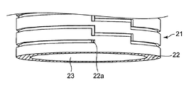
- the secondary coil 26 formed along the outer peripheral surface of the cylindrical body portion 22 is formed by, for example, the MID molding method as shown in FIGS. 5 to 7B.
- the MID molding method is a method in which a molded product formed of a mixture of a resin and a conductive material is irradiated with a laser on a predetermined pattern, the resin is removed, and then the exposed conductive material is subjected to metal plating. Thus, a desired circuit pattern is formed.
- the secondary coil 26 has a pattern 26a that extends in the circumferential direction along the outer peripheral surface of the cylindrical body 22 and is parallel to the axial direction. Are formed at a predetermined pitch. And the said pattern 26a adjacent on the upper and lower sides is connected by the step-shaped auxiliary pattern 26b (FIG. 7A). Further, as shown in FIG. 7B, the lower end portion of the secondary coil 26 is arranged on the inner peripheral surface of the through hole 23 of the cylindrical body portion 22 through a communication hole 22 a provided in the cylindrical body portion 22. Along the substantially axial direction, it is connected to a lead wire 26c (FIG. 6A) formed by metal plating by the MID molding, for example.
- a lead wire 26c FIG. 6A
- the lead wire 26c is connected to a lead wire 26d provided on the upper surface of the flange portion 24 by metal plating, for example, by MID molding.
- the lead wire 26d is connected to a lead wire 26e (FIG. 7A) formed by metal plating on the back surface of the flange portion 24 through a communication hole 24a (FIG. 6B) provided in the flange portion 24.
- the lead wire 26 e is connected to the upper end of the secondary coil 26. Therefore, the secondary coil 26 forms a closed circuit.
- a light emitting element 33 and a resistor 34 are connected in series to the lead wire 26d formed on the flange 24 (FIG. 6A).
- the light emitting element 33 functions as an example of an operation indicator lamp, and a specific example is a light emitting diode (LED).
- LED light emitting diode
- the light emitting element 33 and the resistor 34 are directly connected to the lead wire 26d of the flange 24. For this reason, there are advantages that the number of parts and the number of assembly steps in the assembly process are small, the productivity is high, and the space-saving electromagnet device 20 can be obtained.
- the spool 21 is provided with a recess 25a for fitting a yoke 32 to be described later in the collar portion 25 thereof.
- the flange 25 is press-fitted with coil terminals 27 and 27 in terminal holes 25b and 25b provided on the side end surfaces thereof (FIG. 4).
- an insulating film 30a is wound around the cylindrical body portion 22 of the spool 21 as an example of an insulating material, and a conductive wire 30b is wound on the insulating film 30a to form the primary coil 30, thereby forming a primary coil. 30 is configured.
- the lead wire from the conductive wire 30b of the primary coil 30 is entangled and soldered to the entangled portions 27a and 27a of the coil terminals 27 and 27 (FIG. 3).
- connection terminals (not shown) can be press-fitted are formed on the flange portion 24 of the spool 21. This is because the spool 21 is also used for assembling other electromagnetic relays.
- the yoke 32 is a magnetic material having an L-shaped cross section, and as shown in FIG. 2, a support portion 32a is formed by cutting out the upper end portion thereof.
- the yoke 32 has a caulking hole 32c in the horizontal portion 32b.
- the iron core body part of the iron core 31 is inserted in the through-hole 23 of the cylindrical body part 22 of the spool 21 around which the primary coil 30 is wound, and the cylindrical body part 22 is connected to one end of the iron core body part.
- the iron core 31 is a magnetic material (FIG. 2) having a T-shaped cross section composed of an iron core body portion having one end 31a and a magnetic pole portion 31b.
- the cross section of the spool 21 can be inserted into the through hole 23 of the cylindrical body 22.
- the movable iron piece 40 is formed of a magnetic material bent into a substantially L-shaped cross section as shown in FIG.
- the movable iron piece 40 is rotatably supported about the support portion 32a of the yoke 32 via a hinge spring 35 fixed to the back surface of the yoke 32, for example, caulking.
- the movable iron piece 40 opposes the horizontal part (plate part) 41 so that the magnetic pole part 31b of the iron core 31 can be contacted / separated.
- the movable iron piece 40 is provided with a notch 42 in the horizontal portion 41 for visually confirming the light emitting element 33.
- the notch 42 is configured to transmit the light emitted by the light emitting element 33 to the outside.
- the contact mechanism 50 has a normally closed fixed contact 51a fixed, for example, a fixed contact terminal 51 fixed by caulking, a movable contact 52a fixed, for example, a movable contact piece 52 fixed by caulking, and a normally open fixed.
- the contact 53a is fixed, for example, a fixed contact terminal 53 that is fixed by caulking.
- the terminal portion 51 b of the fixed contact terminal 51, the terminal portion 52 b of the movable contact piece 52, and the terminal portion 53 b of the fixed contact terminal 53 are press-fitted into the base 11.
- the contact mechanism 50 is formed.
- the movable contact 52a opposes the normally closed fixed contact 51a and the normally open fixed contact 53a so as to be able to contact and separate from each other.
- the card 60 has a recess (not shown) that engages with the lower end portion 43 of the movable iron piece 40 on one side of the opposing front and back sides, while the other side remains.
- An operation projection 61 is provided on one side of the projection.
- the card 60 engages the concave portion with the lower end portion 43 of the movable iron piece 40 assembled to the yoke 32.
- the operation protrusion 61 comes into pressure contact with the movable contact piece 52 through the through hole 51 c of the fixed contact terminal 51.
- the case 70 has a box shape that can be fitted to the base 11, and an engagement hole 71 is provided at the lower edge of the opposing side surface. Further, the case 70 is provided with an operation confirmation window 72 that penetrates the light emitting element 33 so that the light emitting element 33 can be seen on the ceiling surface.
- An example of the operation check window 72 is a transparent window. That is, the operation check window 72 is arranged to face the notch 42 and is configured to guide the light emitted from the light emitting element 33 through the notch 42 and the operation check window 72 to the outside. .
- the operation of the electromagnetic relay 10 will be described.
- the movable contact piece 52 urges the lower end portion 43 of the movable iron piece 40 through the card 60. For this reason, the movable contact 52a is in contact with the normally closed fixed contact 51a.
- the horizontal part 41 of the movable iron piece 40 is separated from the magnetic pole part 31 b of the iron core 31.
- the horizontal part 41 of the movable iron piece 40 is attracted to the magnetic pole part 31b of the iron core 31 by the magnetic lines passing through the iron core 31. Then, against the spring force of the movable contact piece 52, the movable iron piece 40 rotates about the support portion 32 a of the yoke 32, and the lower end portion 43 of the movable iron piece 40 presses the card 60. For this reason, the operation protrusion 61 of the card 60 presses the movable contact piece 52, and the movable contact piece 52 rotates. As a result, after the movable contact 52a is separated from the normally closed fixed contact 51a, it contacts the normally open fixed contact 53a. Thereafter, the horizontal portion 41 of the movable iron piece 40 is attracted to the magnetic pole portion 31 b of the iron core 31.
- the secondary coil 26 is formed by metal plating, the bulk is lower than that of the conventional example, and a small electromagnet device 20 is obtained. Further, according to the present embodiment, it is not necessary to tie the coil lead wire to the coil terminal as in the conventional example, and the connection work is facilitated, so that the electromagnet device 20 with high productivity can be obtained.
- the light emitting element 33 is directly attached to the collar portion 24 of the spool 21. For this reason, it is not necessary to attach the light emitting element 33 to the collar part 24 of the spool 21 via the connection terminal. Furthermore, it is not necessary to electrically connect the light emitting element 33 to the connection terminal via a lead wire.
- the secondary coil 26 is formed on the cylindrical body 22 of the spool 21 in advance by metal plating, for example, by the MID molding method, the winding work of the secondary coil 26 becomes unnecessary, and the productivity is further improved. To do. Further, the light emitting element 33 is lit by an induced current flowing through the secondary coil 26. For this reason, it is not necessary to obtain the power necessary for lighting the light emitting element 33 from an external power source. As a result, it is not necessary to connect the light emitting element 33 to an external power source, and the electromagnet device 20 having a simple structure can be obtained.
- the secondary coil 26 of the electromagnet device 20 is provided with a step-like auxiliary pattern 26b in a part thereof, but a smoothly continuous spiral secondary coil may be formed.
- the communication holes 22a and 24a of the spool 21 may be formed in a mortar shape in order to facilitate laser irradiation performed by the MID molding method.
- the electromagnet device is to solve the above problems.
- a spool having a cylindrical body with a through hole;
- a secondary coil that is spirally formed along the outer peripheral surface of the cylindrical body and is formed by forming a closed circuit with metal plating; and
- a primary coil composed of a conductive wire wound around the secondary coil via an insulating material covering the secondary coil, and an electromagnet device comprising:
- a dielectric current generated by applying a voltage to one of the primary coil and the secondary coil is passed through the other coil different from the one coil.
- the secondary coil is formed by metal plating, the bulk is lower than the conventional example, and a small electromagnet device is obtained. Further, according to the first aspect of the present invention, it is not necessary to tie the coil lead wire to the coil terminal as in the conventional example, and the connection work is facilitated, so that an electromagnet device with high productivity can be obtained. .
- At least one end of the cylindrical body is provided with a flange, and both ends of the secondary coil formed on the outer peripheral surface of the body are connected to the cylindrical shape.
- the both ends of a secondary coil are connected by metal plating, it is not necessary to connect with the lead wire of an electroconductive wire. For this reason, an occupation space is small and it can further reduce in size. Further, since the connection work is simplified and labor can be saved, an electromagnet device with higher productivity can be obtained.
- an operation indicator lamp fixed to the collar portion and electrically connected to the secondary coil may be provided.
- the operation indicator lamp provided in the collar part is electrically connected to the secondary coil, the operation
- the operation indicator lamp is directly installed on the buttock, a large wiring space is not required and the apparatus can be miniaturized.
- the operation indicator lamp is turned on by an induced current generated when a voltage is applied to the primary coil, an energy saving type electromagnet device can be obtained.
- the operation indicator lamp may be a light emitting diode (LED).
- the electromagnet apparatus provided with the energy saving type operation indicator lamp can be obtained.
- the electromagnetic relay according to the fifth aspect of the present invention has a configuration in which the above-described electromagnet device according to any one of the first to fourth aspects is incorporated in the base.
- the electromagnet device is smaller in volume and smaller than the conventional example. For this reason, a small electromagnetic relay is obtained. Further, it is not necessary to tie the coil lead wire to the coil terminal as in the conventional example, and the connection work is facilitated, and a highly productive electromagnetic relay can be obtained.
- the iron core inserted into the through hole of the spool by a magnetic force generated by applying a voltage to either the primary coil or the secondary coil.
- a movable iron piece is disposed so as to be attracted to the magnetic pole portion of the iron core protruding from the flange provided at at least one end of the cylindrical body portion, and the light of the operation indicator lamp is applied to the movable iron piece.
- an operation confirmation window for transmitting the light of the operation indicator lamp may be provided in the outer peripheral surface of the case fitted to the base. According to the 7th aspect, an operation indicator lamp can be confirmed through the operation confirmation window provided in the case, and an easy-to-use electromagnetic relay can be obtained.
- the operation check window may be a transparent window provided in a case.
- the eighth aspect since no through hole is provided in the case, there is an effect that a failure based on the intrusion of dust or the like does not occur and a highly reliable electromagnetic relay can be obtained.
- it can be made to show the effect which each has by combining arbitrary embodiment or modification of the said various embodiment or modification suitably.
- combinations of the embodiments, combinations of the examples, or combinations of the embodiments and examples are possible, and combinations of features in different embodiments or examples are also possible.
- the electromagnet device and the electromagnetic relay using the same according to the present invention are not limited to the above-described electromagnet device, and may be applied to other electromagnet devices and electromagnetic relays incorporating the electromagnet device.
Landscapes
- Physics & Mathematics (AREA)
- Electromagnetism (AREA)
- Electromagnets (AREA)
- Switch Cases, Indication, And Locking (AREA)
Abstract
貫通孔(23)を備えた筒状胴部(22)を有するスプール(21)と、前記筒状胴部(22)の外周面に沿って螺旋状に、かつ、金属メッキで閉回路を形成するように形成された二次コイル(26)と、前記二次コイル(26)を被覆する絶縁材(30a)を介して巻回する導電性ワイヤ(30b)で形成された一次コイル(30)と、を備える電磁石装置(20)である。そして、前記一次コイル(30)と前記二次コイル(26)とのうちのいずれか一方のコイルに電圧を印加して発生した誘電電流を、前記一方のコイルとは異なる他方のコイルに流す。
Description
本発明は、電磁石装置、特に、コイルを二重巻線し、電磁継電器に組み込まれる電磁石装置及びこれを用いた電磁継電器に関する。
従来、コイルを二重巻線した電磁石装置としては、例えば、特許文献1の図8に示すように、ボビン113にコイル112を二層に巻回して形成したボビン完成体111がある。そして、図8には、前記ボビン完成体111をベース116に組み込んだ電磁継電器が開示されている。
しかしながら、前記ボビン完成体111は、ボビン113にコイル112を二層に巻回しているので、嵩高くなり、装置を小型化できない。
また、前記ボビン完成体111では、前記コイル112の引出線112a,112a’を外部接続端子114a、114a’に巻回する必要がある。同様に、前記コイル112の引出線112b,112b’を外部接続端子114b,114b’に巻回する必要がある。このため、前記ボビン完成体111は前記コイル112の接続作業に手間がかかり、生産性が低いという問題点がある。
本発明は、前記問題点に鑑み、小型で生産性の高い電磁石装置及びこれを用いた電磁継電器を提供することを課題とする。
また、前記ボビン完成体111では、前記コイル112の引出線112a,112a’を外部接続端子114a、114a’に巻回する必要がある。同様に、前記コイル112の引出線112b,112b’を外部接続端子114b,114b’に巻回する必要がある。このため、前記ボビン完成体111は前記コイル112の接続作業に手間がかかり、生産性が低いという問題点がある。
本発明は、前記問題点に鑑み、小型で生産性の高い電磁石装置及びこれを用いた電磁継電器を提供することを課題とする。
本発明の1つの態様に係る電磁石装置は、前記課題を解決すべく、
貫通孔を備えた筒状胴部を有するスプールと、
前記筒状胴部の外周面に沿って螺旋状に、かつ、金属メッキで閉回路を形成して構成された二次コイルと、
前記二次コイルを被覆する絶縁材を介して前記二次コイルの周囲に巻回する導電性ワイヤで構成された一次コイルと、を備える電磁石装置であって、
前記一次コイルと前記二次コイルとのうちのいずれか一方のコイルに電圧を印加して発生した誘電電流を、前記一方のコイルとは異なる他方のコイルに流す構成としてある。
貫通孔を備えた筒状胴部を有するスプールと、
前記筒状胴部の外周面に沿って螺旋状に、かつ、金属メッキで閉回路を形成して構成された二次コイルと、
前記二次コイルを被覆する絶縁材を介して前記二次コイルの周囲に巻回する導電性ワイヤで構成された一次コイルと、を備える電磁石装置であって、
前記一次コイルと前記二次コイルとのうちのいずれか一方のコイルに電圧を印加して発生した誘電電流を、前記一方のコイルとは異なる他方のコイルに流す構成としてある。
本発明の前記態様によれば、二次コイルを金属メッキで形成するので、従来例よりも嵩が低く、小型の電磁石装置が得られる。また、本発明の前記態様によれば、従来例のようにコイルの引出線をコイル端子に絡げる必要がなく、接続作業が容易になるので、生産性の高い電磁石装置が得られる。
本発明のこれらと他の目的と特徴は、添付された図面についての実施形態に関連した次の記述から明らかになる。この図面においては、
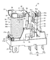
本発明の実施形態に係る電磁石装置を組み込んだ電磁継電器を示す斜視図であり、
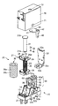
本発明の実施形態に係る電磁石装置を組み込んだ電磁継電器の分解斜視図であり、
図1からベースを消去した状態を示す斜視図であり、
図3から一次コイルを消去した状態を示す斜視図であり、
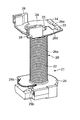
図4に示したスプールを示す斜視図であり、
図5の縦断面斜視図であり、
図6Aの部分拡大斜視図であり、
図5を別の視点から見た横断面斜視図であり、
図7Aの部分拡大斜視図であり、
特許文献1の電磁石装置の斜視図である。
本発明の記述を続ける前に、添付図面において同じ部品については同じ参照符号を付している。
本発明の実施形態を説明するにあたり、図面に表された構成を説明するうえで、「上」、「下」、「左」、「右」等の方向を表す用語、及び、それらを含む別の用語を使用するが、それらの用語を使用する目的は図面を通じて実施形態の理解を容易にするためである。したがって、それらの用語は、本発明の実施形態が実際に使用されるときの方向を示すものとは限らないし、それらの用語によって特許請求の範囲に記載された技術的範囲が限定的に解釈されるべきではない。
本発明の実施形態に係る電磁石装置を、図1~図7Bの添付図面に従い、電磁継電器に組み込んだ場合について説明する。
前記電磁継電器10は、図2に示すように、ベース11と、前記ベース11に設置する電磁石装置20と、前記電磁石装置20の励磁及び消磁に基づいて回動する可動鉄片40と、前記ベース11に搭載される接点機構50と、前記可動鉄片40を介して前記接点機構50を駆動するカード60と、ケース70と、を備えている。なお、説明の便宜上、図1において、ケース70(図2参照)は図示されていない。
前記電磁継電器10は、図2に示すように、ベース11と、前記ベース11に設置する電磁石装置20と、前記電磁石装置20の励磁及び消磁に基づいて回動する可動鉄片40と、前記ベース11に搭載される接点機構50と、前記可動鉄片40を介して前記接点機構50を駆動するカード60と、ケース70と、を備えている。なお、説明の便宜上、図1において、ケース70(図2参照)は図示されていない。
ベース11は、図1及び図2に示すように、その上面の一方側に電磁石装置20を設置するための配置スペース12を設けてある。また、前記ベース11は、その上面の他方側に、接点機構50を構成するために3つの端子孔(図示せず)を設けてある。
前記配置スペース12は、図2において手前側の隣り合う隅部に、前記電磁石装置20のコイル端子27,27を圧入するための端子孔(図示せず)を設けてある。また、前記配置スペース12は、図2において奥側隅部に平面門型のリブ13を設けてある。前記リブ13は、その内側面の隅部に後述するヨーク32を圧入するための圧入溝14を設けてある。そして、前記リブ13は、対向する外側面に、後述するケース70を固定するための係合爪部15を設けてある。
前記配置スペース12は、図2において手前側の隣り合う隅部に、前記電磁石装置20のコイル端子27,27を圧入するための端子孔(図示せず)を設けてある。また、前記配置スペース12は、図2において奥側隅部に平面門型のリブ13を設けてある。前記リブ13は、その内側面の隅部に後述するヨーク32を圧入するための圧入溝14を設けてある。そして、前記リブ13は、対向する外側面に、後述するケース70を固定するための係合爪部15を設けてある。
電磁石装置20は、図2に示すように、スプール21と、一次コイル30と、鉄芯31と、ヨーク32とで構成されている。
前記スプール21は、図5に示すように、筒状胴部22と、前記筒状胴部22の軸方向の両端に一体成形された鍔部24,25とで形成されている。
前記筒状胴部22は、図6A及び図6Bに示すように、その内側に断面T字形状の鉄芯31を上部開口から挿入して抜け止めできる貫通孔23を設けてある。また、前記筒状胴部22の外周面に沿って形成された二次コイル26は、図5~図7Bに示すように、例えばMID成形法によって形成されている。前記MID成形法とは、樹脂と導電素材とを混合した材料で形成した成形品に、予め決められたパターンにレーザ照射し、樹脂を除去した後、露出する前記導電素材に金属メッキを施すことにより、所望の回路パターンを形成する方法である。
前記筒状胴部22は、図6A及び図6Bに示すように、その内側に断面T字形状の鉄芯31を上部開口から挿入して抜け止めできる貫通孔23を設けてある。また、前記筒状胴部22の外周面に沿って形成された二次コイル26は、図5~図7Bに示すように、例えばMID成形法によって形成されている。前記MID成形法とは、樹脂と導電素材とを混合した材料で形成した成形品に、予め決められたパターンにレーザ照射し、樹脂を除去した後、露出する前記導電素材に金属メッキを施すことにより、所望の回路パターンを形成する方法である。
本実施形態において、前記二次コイル26は、図5及び図7A及び図7Bに示すように、前記筒状胴部22の外周面に沿って周方向に延びかつ軸方向に互いに平行なパターン26aを所定のピッチで形成してある。そして、上下で隣り合う前記パターン26aは、階段状の補助パターン26b(図7A)で接続されている。
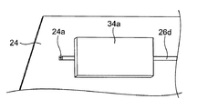
また、前記二次コイル26の下方端部は、図7Bに示すように、前記筒状胴部22に設けた連通孔22aを介し、前記筒状胴部22の貫通孔23の内周面において略軸方向沿いに例えば前記MID成形で金属メッキにより形成したリード線26c(図6A)に接続されている。前記リード線26cは、鍔部24の上面に例えばMID成形法で金属メッキにより設けたリード線26dに接続されている。前記リード線26dは、前記鍔部24に設けた連通孔24a(図6B)を介し、前記鍔部24の裏面に金属メッキにより形成したリード線26e(図7A)に接続されている。そして、前記リード線26eは前記二次コイル26の上方端部に接続されている。したがって、二次コイル26は閉回路を形成している。
なお、前記鍔部24に形成したリード線26dに、発光素子33と抵抗34とが直列に接続されている(図6A)。発光素子33は、動作表示灯の一例として機能し、具体例としては発光ダイオード(LED)である。
本実施形態では、前記鍔部24のリード線26dに発光素子33と抵抗34とを直接、接続している。このため、組立工程における部品点数及び組立工数が少なく、生産性が高いとともに、省スペース型の電磁石装置20が得られるという利点がある。
また、前記二次コイル26の下方端部は、図7Bに示すように、前記筒状胴部22に設けた連通孔22aを介し、前記筒状胴部22の貫通孔23の内周面において略軸方向沿いに例えば前記MID成形で金属メッキにより形成したリード線26c(図6A)に接続されている。前記リード線26cは、鍔部24の上面に例えばMID成形法で金属メッキにより設けたリード線26dに接続されている。前記リード線26dは、前記鍔部24に設けた連通孔24a(図6B)を介し、前記鍔部24の裏面に金属メッキにより形成したリード線26e(図7A)に接続されている。そして、前記リード線26eは前記二次コイル26の上方端部に接続されている。したがって、二次コイル26は閉回路を形成している。
なお、前記鍔部24に形成したリード線26dに、発光素子33と抵抗34とが直列に接続されている(図6A)。発光素子33は、動作表示灯の一例として機能し、具体例としては発光ダイオード(LED)である。
本実施形態では、前記鍔部24のリード線26dに発光素子33と抵抗34とを直接、接続している。このため、組立工程における部品点数及び組立工数が少なく、生産性が高いとともに、省スペース型の電磁石装置20が得られるという利点がある。
また、前記スプール21は、図6Aに示すように、その鍔部25に、後述するヨーク32を嵌合するための凹所25aを設けてある。また、前記鍔部25は、図5に示すように、その側端面に設けた端子孔25b,25bに、コイル端子27,27をそれぞれ圧入してある(図4)。そして、前記スプール21の筒状胴部22に絶縁材の例として絶縁フィルム30aを巻回し、さらに、絶縁フィルム30a上に導電性ワイヤ30bを巻回して一次コイル30を形成することにより、一次コイル30を構成する。次いで、前記一次コイル30の導電性ワイヤ30bからの引き出し線を前記コイル端子27,27の絡げ部27a,27aに絡げて半田付けしてある(図3)。
なお、本実施形態では、スプール21の鍔部24に、接続端子(図示せず)を圧入可能なリブ28,28を形成してある。前記スプール21を他の電磁継電器の組立に兼用するためである。
前記ヨーク32は断面L字形状の磁性材であり、図2に示すように、その上端部を切り欠いて支持部32aを形成してある。また、前記ヨーク32は、その水平部32bにカシメ孔32cを有している。そして、一次コイル30を巻回したスプール21の筒状胴部22の貫通孔23内に鉄芯31の鉄芯胴部を挿入し、鉄芯胴部の一端に連結されて筒状胴部22の一端から鍔状に突出する一端部31aを前記ヨーク32のカシメ孔32cに固定、例えばカシメ固定する一方、鉄芯胴部の他端に連結されて筒状胴部22の他端から鍔状に突出する他端部を磁極部31bとしてある。よって、鉄芯31は、一端部31aを有する鉄芯胴部と、磁極部31bとで構成される断面T字形状の磁性材(図2)であって、鉄芯31の鉄芯胴部は、前記スプール21の筒状胴部22の貫通孔23に挿通可能な断面積を有している。
前記可動鉄片40は、図2に示すように、断面略L字形状に屈曲した磁性材で形成されている。そして、前記可動鉄片40は、ヨーク32の背面に固定、例えばカシメ固定されたヒンジバネ35を介し、前記ヨーク32の支持部32aを支点として回動可能に支持される。これにより、可動鉄片40は、その水平部(板部)41が鉄芯31の磁極部31bに接離可能に対向する。なお、前記可動鉄片40は、前記水平部41に、発光素子33を目視で確認するための切欠き部42を設けてある。言い換えれば、切欠き部42は、発光素子33で発光された光を外部に透過させるように構成している。
前記接点機構50は、図3に示すように、常閉固定接点51aを固定、例えばカシメ固定した固定接点端子51と、可動接点52aを固定、例えばカシメ固定した可動接触片52と、常開固定接点53aを固定、例えばカシメ固定した固定接点端子53と、で構成されている。そして、図1に示すように、前記ベース11に、前記固定接点端子51の端子部51bと、前記可動接触片52の端子部52bと、前記固定接点端子53の端子部53bとを圧入することにより、接点機構50が形成される。これにより、可動接点52aが常閉固定接点51a及び常開固定接点53aにそれぞれ接離可能に対向する。
前記カード60は、図1~図4に示すように、対向する表裏面のうち、一方の片面に前記可動鉄片40の下端部43に係合する凹部(図示せず)を有する一方、残る他方の片面に操作用突起61を突設してある。そして、前記カード60は、前記凹部を、ヨーク32に組み付けた可動鉄片40の下端部43に係合する。これにより、前記操作用突起61が前記固定接点端子51の貫通孔51cを介して前記可動接触片52に圧接する。
前記ケース70は、前記ベース11に嵌合可能な箱形状を有し、その対向する側面の下辺縁部に係合孔71を設けてある。また、前記ケース70は、その天井面に、前記発光素子33を目視できる貫通した動作確認窓72を設けてある。動作確認窓72の一例としては透明窓である。すなわち、動作確認窓72は、切欠き部42に対向して配置され、発光素子33で発光された光を切欠き部42及び動作確認窓72を透過して外部に導くように構成している。
次に、電磁継電器10の動作について説明する。
まず、電磁石装置20の一次コイル30に電圧が印加されていない場合には、図1に示すように、二次コイル26に誘導電流が発生しておらず、発光素子33は点灯していない。また、可動接触片52が、カード60を介して可動鉄片40の下端部43を付勢している。このため、可動接点52aが常閉固定接点51aに接触している。そして、可動鉄片40の水平部41が鉄芯31の磁極部31bから開離している。
まず、電磁石装置20の一次コイル30に電圧が印加されていない場合には、図1に示すように、二次コイル26に誘導電流が発生しておらず、発光素子33は点灯していない。また、可動接触片52が、カード60を介して可動鉄片40の下端部43を付勢している。このため、可動接点52aが常閉固定接点51aに接触している。そして、可動鉄片40の水平部41が鉄芯31の磁極部31bから開離している。
そして、一次コイル30に電圧を印加して励磁すると、鉄芯31を通過する磁力線により、鉄芯31の磁極部31bに可動鉄片40の水平部41が吸引される。そして、可動接触片52のばね力に抗し、可動鉄片40がヨーク32の支持部32aを支点として回動し、前記可動鉄片40の下端部43がカード60を押圧する。このため、前記カード60の操作用突起61が可動接触片52を押圧し、前記可動接触片52が回動する。この結果、可動接点52aが常閉固定接点51aから開離した後、常開固定接点53aに接触する。その後、可動鉄片40の水平部41が鉄芯31の磁極部31bに吸着する。
また、一次コイル30に電圧を印加した場合には、電磁誘導で二次コイル26に誘導電流が流れ、リード線26dなどを介して発光素子33が点灯する。そして、発光素子33の上方に設けた可動鉄片40の切欠き部42及び動作確認窓72を介して発光素子33の光が透過し、発光素子33が点灯しているか否かを、ケース70の動作確認窓72から確認できる。このため、本実施形態では、一次コイル30に電圧が印加されている間は、発光素子33が発光し続けるので、電磁継電器10が動作しているか否かを電磁継電器10の外部から判別できる。
なお、ケース70は、その少なくとも一部が、発光素子33の光を外部から目視できるように、透光性を有する、あるいは、透明な動作確認窓72を有していてもよい。
なお、ケース70は、その少なくとも一部が、発光素子33の光を外部から目視できるように、透光性を有する、あるいは、透明な動作確認窓72を有していてもよい。
次いで、一次コイル30への電圧の印加を停止すると、鉄芯31を通過する磁力線が消失し、可動接触片52がカード60を介して可動鉄片40を押し戻す。このため、可動接点52aは常開固定接点53aから開離した後、常閉固定接点51aに接触し、元の位置に復帰する。そして、二次コイル26に流れていた誘導電流が消失し、発光素子33が消灯する。これにより、電磁継電器10が動作を停止したことを目視で確認できる。
本実施形態によれば、二次コイル26を金属メッキで形成するので、従来例よりも嵩が低く、小型の電磁石装置20が得られる。また、本実施形態によれば、従来例のようにコイルの引出線をコイル端子に絡げる必要がなく、接続作業が容易になるので、生産性の高い電磁石装置20が得られる。
本実施形態では、スプール21の鍔部24に発光素子33を直接取り付けてある。このため、スプール21の鍔部24に接続端子を介して発光素子33を取り付ける必要がない。さらに、前記接続端子にリード線を介して前記発光素子33を電気接続する必要もない。この結果、接続端子の組付け作業及び半田付け作業が不要となり、部品点数及び組立工数が少なく、生産性の高い電磁石装置が得られる。
また、スプール21の筒状胴部22に二次コイル26を金属メッキ、例えばMID成形法で予め形成してあるので、二次コイル26の巻線作業が不要となり、より一層、生産性が向上する。
さらに、前記発光素子33は、二次コイル26に流れる誘導電流で点灯する。このため、前記発光素子33を点灯するために必要な電力を、外部電源から得る必要がない。この結果、前記発光素子33を外部電源に接続する必要がなく、簡単な構造の電磁石装置20が得られる。
本実施形態では、スプール21の鍔部24に発光素子33を直接取り付けてある。このため、スプール21の鍔部24に接続端子を介して発光素子33を取り付ける必要がない。さらに、前記接続端子にリード線を介して前記発光素子33を電気接続する必要もない。この結果、接続端子の組付け作業及び半田付け作業が不要となり、部品点数及び組立工数が少なく、生産性の高い電磁石装置が得られる。
また、スプール21の筒状胴部22に二次コイル26を金属メッキ、例えばMID成形法で予め形成してあるので、二次コイル26の巻線作業が不要となり、より一層、生産性が向上する。
さらに、前記発光素子33は、二次コイル26に流れる誘導電流で点灯する。このため、前記発光素子33を点灯するために必要な電力を、外部電源から得る必要がない。この結果、前記発光素子33を外部電源に接続する必要がなく、簡単な構造の電磁石装置20が得られる。
なお、本実施形態に係る電磁石装置20の二次コイル26は、その一部に階段状の補助パターン26bを設けてあるが、滑らかに連続する螺旋状の二次コイルを形成してもよい。
また、前記スプール21の連通孔22a,24aは、MID成形法で行うレーザ照射を容易にするため、すり鉢状に形成しておいてもよい。
また、前記スプール21の連通孔22a,24aは、MID成形法で行うレーザ照射を容易にするため、すり鉢状に形成しておいてもよい。
以上、図面を参照して本発明における種々の実施形態を詳細に説明したが、最後に、本発明の種々の態様について説明する。
本発明の第1態様に係る電磁石装置は、前記課題を解決すべく、
貫通孔を備えた筒状胴部を有するスプールと、
前記筒状胴部の外周面に沿って螺旋状に、かつ、金属メッキで閉回路を形成して構成された二次コイルと、
前記二次コイルを被覆する絶縁材を介して前記二次コイルの周囲に巻回する導電性ワイヤで構成された一次コイルと、を備える電磁石装置であって、
前記一次コイルと前記二次コイルとのうちのいずれか一方のコイルに電圧を印加して発生した誘電電流を、前記一方のコイルとは異なる他方のコイルに流す構成としてある。
本発明の第1態様に係る電磁石装置は、前記課題を解決すべく、
貫通孔を備えた筒状胴部を有するスプールと、
前記筒状胴部の外周面に沿って螺旋状に、かつ、金属メッキで閉回路を形成して構成された二次コイルと、
前記二次コイルを被覆する絶縁材を介して前記二次コイルの周囲に巻回する導電性ワイヤで構成された一次コイルと、を備える電磁石装置であって、
前記一次コイルと前記二次コイルとのうちのいずれか一方のコイルに電圧を印加して発生した誘電電流を、前記一方のコイルとは異なる他方のコイルに流す構成としてある。
本発明の前記第1態様によれば、二次コイルを金属メッキで形成するので、従来例よりも嵩が低く、小型の電磁石装置が得られる。また、本発明の前記第1態様によれば、従来例のようにコイルの引出線をコイル端子に絡げる必要がなく、接続作業が容易になるので、生産性の高い電磁石装置が得られる。
本発明の第2態様としては、第1態様において、前記筒状胴部の少なくとも一端に鍔部を設けるとともに、前記胴部の外周面に形成された前記二次コイルの両端を、前記筒状胴部及び前記鍔部に設けた連通孔及び前記筒状胴部の前記貫通孔の内周面を介して、金属メッキで形成されたリード線で電気接続しておいてもよい。
第2態様によれば、二次コイルの両端を金属メッキで接続するので、導電性ワイヤのリード線で接続する必要がない。このため、占有スペースが小さく、より一層小型できる。また、接続作業が簡単になり、省力化できるので、より一層生産性の高い電磁石装置が得られる。
第2態様によれば、二次コイルの両端を金属メッキで接続するので、導電性ワイヤのリード線で接続する必要がない。このため、占有スペースが小さく、より一層小型できる。また、接続作業が簡単になり、省力化できるので、より一層生産性の高い電磁石装置が得られる。
本発明の第3態様としては、第2態様において、前記鍔部に固定され、かつ、前記二次コイルに電気接続された動作表示灯を設けておいてもよい。
第3態様によれば、鍔部に設けられた動作表示灯が二次コイルに電気接続されているので、動作表示灯の接続作業が容易である。また、鍔部に動作表示灯を直接、設置しているので、大きな配線スペースを必要とせず、装置を小型化できる。さらに、一次コイルに電圧を印加したときに生じる誘導電流で動作表示灯を点灯するので、省エネルギータイプの電磁石装置が得られる。
第3態様によれば、鍔部に設けられた動作表示灯が二次コイルに電気接続されているので、動作表示灯の接続作業が容易である。また、鍔部に動作表示灯を直接、設置しているので、大きな配線スペースを必要とせず、装置を小型化できる。さらに、一次コイルに電圧を印加したときに生じる誘導電流で動作表示灯を点灯するので、省エネルギータイプの電磁石装置が得られる。
本発明の第4態様としては、第3態様において、前記動作表示灯が発光ダイオード(LED)であってもよい。
第4態様によれば、より一層、省エネルギータイプの動作表示灯を備えた電磁石装置が得られる。
第4態様によれば、より一層、省エネルギータイプの動作表示灯を備えた電磁石装置が得られる。
本発明の第5態様に係る電磁継電器は、ベースに、第1~第4態様のいずれか1つの前述の電磁石装置を組み込んだ構成としてある。
本発明の第5態様によれば、二次コイルを金属メッキで形成してあるので、電磁石装置が従来例よりも嵩が低く、小型になる。このため、小型の電磁継電器が得られる。また、従来例のようにコイルの引出線をコイル端子に絡げる必要がなく、接続作業が容易になり、生産性の高い電磁継電器が得られる。
本発明の第6態様としては、第5態様において、前記一次コイルまたは前記二次コイルのいずれか一方に電圧を印加して生じた磁力により、前記スプールの前記貫通孔に挿通された鉄芯のうち、前記筒状胴部の少なくとも一端に設けられた鍔部から突出する前記鉄芯の磁極部に吸引されるように可動鉄片を配置するとともに、前記可動鉄片に、前記動作表示灯の光を透過させる切欠き部を設けておいてもよい。
第6態様によれば、電磁石装置の鍔部に設けた動作表示灯の光が、可動鉄片に設けた切欠き部を介して透過するので、目視で確認できる。このため、動作状態を、前記切欠き部を介して目視で確認できるので、安全性が高く、使用者が安心感を得られる電磁継電器が得られる。
第6態様によれば、電磁石装置の鍔部に設けた動作表示灯の光が、可動鉄片に設けた切欠き部を介して透過するので、目視で確認できる。このため、動作状態を、前記切欠き部を介して目視で確認できるので、安全性が高く、使用者が安心感を得られる電磁継電器が得られる。
本発明の第7態様としては、第6態様において、前記ベースに嵌合したケースの外周面のうち、前記動作表示灯の光を透過させる動作確認窓を設けておいてもよい。
第7態様によれば、ケースに設けた動作確認窓を介して動作表示灯を確認でき、使い勝手のよい電磁継電器が得られる。
第7態様によれば、ケースに設けた動作確認窓を介して動作表示灯を確認でき、使い勝手のよい電磁継電器が得られる。
本発明の第8態様としては、第7態様において、前記動作確認窓が、ケースに設けた透明窓であってもよい。
第8態様によれば、ケースに貫通孔を設けていないので、塵埃等の侵入に基づく故障が生じず、信頼性の高い電磁継電器が得られるという効果がある。
なお、前記様々な実施形態又は変形例のうちの任意の実施形態又は変形例を適宜組み合わせることにより、それぞれの有する効果を奏するようにすることができる。また、実施形態同士の組み合わせ又は実施例同士の組み合わせ又は実施形態と実施例との組み合わせが可能であると共に、異なる実施形態又は実施例の中の特徴同士の組み合わせも可能である。
第8態様によれば、ケースに貫通孔を設けていないので、塵埃等の侵入に基づく故障が生じず、信頼性の高い電磁継電器が得られるという効果がある。
なお、前記様々な実施形態又は変形例のうちの任意の実施形態又は変形例を適宜組み合わせることにより、それぞれの有する効果を奏するようにすることができる。また、実施形態同士の組み合わせ又は実施例同士の組み合わせ又は実施形態と実施例との組み合わせが可能であると共に、異なる実施形態又は実施例の中の特徴同士の組み合わせも可能である。
本発明にかかる電磁石装置及びこれを用いた電磁継電器は、前述の電磁石装置に限らず、他の電磁石装置及びこれを組み込んだ電磁継電器に適用してもよい。
10 電磁継電器
11 ベース
12 配置スペース
13 リブ
14 圧入溝
15 係合爪部
20 電磁石装置
21 スプール
22 筒状胴部
22a 連通孔
23 貫通孔
24 鍔部
25 鍔部
24a 連通孔
26 二次コイル
26a パターン
26b 補助パターン
26c リード線
26d リード線
26e リード線
30 一次コイル
31 鉄芯
31b 磁極部
32 ヨーク
33 発光素子
34 抵抗
35 ヒンジバネ
40 可動鉄片
41 水平部
42 切欠き部
50 接点機構
51 固定接点端子
51a 常閉固定接点
52 可動接触片
52a 可動接点
53 固定接点端子
53a 常開固定接点
60 カード
61 操作用突起
70 ケース
71 係合孔
72 動作確認窓
本発明は、添付図面を参照しながら好ましい実施形態に関連して充分に記載されているが、この技術の熟練した人々にとっては種々の変形又は修正は明白である。そのような変形又は修正は、添付した請求の範囲による本発明の範囲から外れない限りにおいて、その中に含まれると理解されるべきである。
11 ベース
12 配置スペース
13 リブ
14 圧入溝
15 係合爪部
20 電磁石装置
21 スプール
22 筒状胴部
22a 連通孔
23 貫通孔
24 鍔部
25 鍔部
24a 連通孔
26 二次コイル
26a パターン
26b 補助パターン
26c リード線
26d リード線
26e リード線
30 一次コイル
31 鉄芯
31b 磁極部
32 ヨーク
33 発光素子
34 抵抗
35 ヒンジバネ
40 可動鉄片
41 水平部
42 切欠き部
50 接点機構
51 固定接点端子
51a 常閉固定接点
52 可動接触片
52a 可動接点
53 固定接点端子
53a 常開固定接点
60 カード
61 操作用突起
70 ケース
71 係合孔
72 動作確認窓
本発明は、添付図面を参照しながら好ましい実施形態に関連して充分に記載されているが、この技術の熟練した人々にとっては種々の変形又は修正は明白である。そのような変形又は修正は、添付した請求の範囲による本発明の範囲から外れない限りにおいて、その中に含まれると理解されるべきである。
Claims (8)
- 貫通孔を備えた筒状胴部を有するスプールと、
前記筒状胴部の外周面に沿って螺旋状に、かつ、金属メッキで閉回路を形成して構成された二次コイルと、
前記二次コイルを被覆する絶縁材を介して前記二次コイルの周囲に巻回する導電性ワイヤで構成された一次コイルと、
を備える電磁石装置であって、
前記一次コイルと前記二次コイルとのうちのいずれか一方のコイルに電圧を印加して発生した誘電電流を、前記一方のコイルとは異なる他方のコイルに流す電磁石装置。 - 前記筒状胴部の少なくとも一端に鍔部を設けるとともに、前記筒状胴部の外周面に形成された前記二次コイルの両端を、前記筒状胴部及び前記鍔部に設けた連通孔及び前記筒状胴部の前記貫通孔の内周面を介して、金属メッキで形成されたリード線で電気接続する請求項1に記載の電磁石装置。
- 前記鍔部に固定され、かつ、前記二次コイルに電気接続された動作表示灯を有する請求項2に記載の電磁石装置。
- 前記動作表示灯が発光ダイオードである請求項3に記載の電磁石装置。
- ベースに、請求項1~4のいずれか1項に記載の前記電磁石装置を組み込んだ電磁継電器。
- 前記一次コイルまたは前記二次コイルのいずれか一方に電圧を印加して生じた磁力により、前記スプールの前記貫通孔に挿通された鉄芯のうち、前記筒状胴部の少なくとも一端に設けられた鍔部から突出する前記鉄芯の磁極部に吸引されるように可動鉄片を配置するとともに、
前記可動鉄片に、前記動作表示灯の光を透過させる切欠き部を設ける請求項5に記載の電磁継電器。 - 前記ベースに嵌合したケースの外周面のうち、前記動作表示灯の光を透過させる動作確認窓を設ける請求項6に記載の電磁継電器。
- 前記動作確認窓が、前記ケースに設けた透明窓である請求項7に記載の電磁継電器。
Priority Applications (3)
| Application Number | Priority Date | Filing Date | Title |
|---|---|---|---|
| DE112016004104.7T DE112016004104B4 (de) | 2015-09-11 | 2016-08-26 | Elektromagnetische vorrichtung und elektromagnetisches relais, das diese verwendet |
| CN201680040700.0A CN107851542B (zh) | 2015-09-11 | 2016-08-26 | 电磁铁装置及采用了该电磁铁装置的电磁继电器 |
| US15/876,072 US10685801B2 (en) | 2015-09-11 | 2018-01-19 | Electromagnetic device and electromagnetic relay using same |
Applications Claiming Priority (2)
| Application Number | Priority Date | Filing Date | Title |
|---|---|---|---|
| JP2015-179236 | 2015-09-11 | ||
| JP2015179236A JP6657692B2 (ja) | 2015-09-11 | 2015-09-11 | 電磁石装置およびこれを用いた電磁継電器 |
Related Child Applications (1)
| Application Number | Title | Priority Date | Filing Date |
|---|---|---|---|
| US15/876,072 Continuation US10685801B2 (en) | 2015-09-11 | 2018-01-19 | Electromagnetic device and electromagnetic relay using same |
Publications (1)
| Publication Number | Publication Date |
|---|---|
| WO2017043345A1 true WO2017043345A1 (ja) | 2017-03-16 |
Family
ID=58240668
Family Applications (1)
| Application Number | Title | Priority Date | Filing Date |
|---|---|---|---|
| PCT/JP2016/075079 Ceased WO2017043345A1 (ja) | 2015-09-11 | 2016-08-26 | 電磁石装置及びこれを用いた電磁継電器 |
Country Status (5)
| Country | Link |
|---|---|
| US (1) | US10685801B2 (ja) |
| JP (1) | JP6657692B2 (ja) |
| CN (1) | CN107851542B (ja) |
| DE (1) | DE112016004104B4 (ja) |
| WO (1) | WO2017043345A1 (ja) |
Families Citing this family (7)
| Publication number | Priority date | Publication date | Assignee | Title |
|---|---|---|---|---|
| JP6459739B2 (ja) * | 2015-04-13 | 2019-01-30 | オムロン株式会社 | 端子の接続構造およびこれを用いた電磁継電器 |
| JP6939592B2 (ja) | 2018-01-22 | 2021-09-22 | オムロン株式会社 | 電磁継電器および端子台 |
| CN110970268A (zh) * | 2018-09-30 | 2020-04-07 | 泰科电子(深圳)有限公司 | 电磁继电器 |
| CN110970266A (zh) * | 2018-09-30 | 2020-04-07 | 泰科电子(深圳)有限公司 | 电磁继电器 |
| JP7596070B2 (ja) * | 2020-01-22 | 2024-12-09 | 株式会社東芝 | チップパッケージ |
| JP7593199B2 (ja) * | 2021-03-30 | 2024-12-03 | オムロン株式会社 | 接点端子および接点装置 |
| JP2024085497A (ja) * | 2022-12-15 | 2024-06-27 | オムロン株式会社 | 電磁石装置 |
Citations (2)
| Publication number | Priority date | Publication date | Assignee | Title |
|---|---|---|---|---|
| JPS5165244U (ja) * | 1974-11-20 | 1976-05-22 | ||
| JPS5990156U (ja) * | 1982-12-09 | 1984-06-19 | オムロン株式会社 | 電磁継電器 |
Family Cites Families (16)
| Publication number | Priority date | Publication date | Assignee | Title |
|---|---|---|---|---|
| US2131942A (en) * | 1935-01-02 | 1938-10-04 | Evans Charles James | Electromagnetic switching system |
| US3037106A (en) * | 1960-07-29 | 1962-05-29 | Du Pont | Heating apparatus |
| EP0372554A3 (en) * | 1988-12-09 | 1992-04-08 | OMRON Corporation | Electromagnetic relay |
| JP2533214B2 (ja) | 1990-03-02 | 1996-09-11 | 富士通株式会社 | 二捲線継電器 |
| WO1992019000A1 (en) * | 1991-04-09 | 1992-10-29 | Omron Corporation | Electromagnetic relay |
| DK1059652T3 (ja) * | 1998-10-20 | 2006-08-21 | Releco Sa | |
| JP4140432B2 (ja) | 2003-04-24 | 2008-08-27 | オムロン株式会社 | 電磁継電器 |
| JP4038507B2 (ja) * | 2004-12-10 | 2008-01-30 | 三菱電機株式会社 | スタータ用電磁スイッチ |
| JP2006266101A (ja) * | 2005-03-22 | 2006-10-05 | Mitsubishi Electric Corp | スタータ用電磁スイッチ |
| JP4706742B2 (ja) * | 2008-09-19 | 2011-06-22 | 富士電機機器制御株式会社 | 電磁接触器のコイルユニットおよびその組立方法 |
| JP5085754B2 (ja) * | 2011-03-14 | 2012-11-28 | オムロン株式会社 | 電磁継電器 |
| WO2012124174A1 (ja) * | 2011-03-14 | 2012-09-20 | オムロン株式会社 | 電磁継電器 |
| JP4883232B1 (ja) * | 2011-03-14 | 2012-02-22 | オムロン株式会社 | 電磁継電器 |
| JP6056264B2 (ja) * | 2012-08-24 | 2017-01-11 | オムロン株式会社 | 電磁石装置およびそれを用いた電磁継電器 |
| JP6263904B2 (ja) * | 2013-08-23 | 2018-01-24 | オムロン株式会社 | 電磁石装置およびこれを用いた電磁継電器 |
| CN103515046B (zh) * | 2013-10-09 | 2016-04-13 | 武汉大学 | 一种组合式并联线圈 |
-
2015
- 2015-09-11 JP JP2015179236A patent/JP6657692B2/ja active Active
-
2016
- 2016-08-26 WO PCT/JP2016/075079 patent/WO2017043345A1/ja not_active Ceased
- 2016-08-26 DE DE112016004104.7T patent/DE112016004104B4/de active Active
- 2016-08-26 CN CN201680040700.0A patent/CN107851542B/zh active Active
-
2018
- 2018-01-19 US US15/876,072 patent/US10685801B2/en active Active
Patent Citations (2)
| Publication number | Priority date | Publication date | Assignee | Title |
|---|---|---|---|---|
| JPS5165244U (ja) * | 1974-11-20 | 1976-05-22 | ||
| JPS5990156U (ja) * | 1982-12-09 | 1984-06-19 | オムロン株式会社 | 電磁継電器 |
Also Published As
| Publication number | Publication date |
|---|---|
| JP2017054758A (ja) | 2017-03-16 |
| DE112016004104T5 (de) | 2018-05-30 |
| DE112016004104B4 (de) | 2023-12-14 |
| CN107851542B (zh) | 2019-06-11 |
| JP6657692B2 (ja) | 2020-03-04 |
| US20180144895A1 (en) | 2018-05-24 |
| CN107851542A (zh) | 2018-03-27 |
| US10685801B2 (en) | 2020-06-16 |
Similar Documents
| Publication | Publication Date | Title |
|---|---|---|
| US10685801B2 (en) | Electromagnetic device and electromagnetic relay using same | |
| JP6071376B2 (ja) | 電磁継電器 | |
| US8354906B2 (en) | Electromagnetic relay | |
| EP3285277B1 (en) | Contact device | |
| JP6399434B2 (ja) | 接点装置 | |
| US10032570B2 (en) | Contact device | |
| KR20140003131A (ko) | 코일 부품과 그 실장 구조, 및 이를 구비하는 전자 기기 | |
| WO2013027447A1 (ja) | トランス | |
| JP2015185725A (ja) | トランス | |
| US9748054B2 (en) | Contact device | |
| JP2017139196A (ja) | 可動子及びこれを用いた接点装置 | |
| JP6344282B2 (ja) | コイル端子およびこれを備えた電磁継電器 | |
| KR101503316B1 (ko) | 전자접촉기 | |
| JP2015220181A (ja) | 接点装置 | |
| JPH0746555B2 (ja) | 電磁継電器 | |
| JP5449585B2 (ja) | 電磁リレー | |
| JP2005243367A (ja) | 有極電磁リレー及びその製造方法 | |
| JP3122289U (ja) | コイル部品 | |
| JP6320135B2 (ja) | 電磁アクチュエータ、電磁アクチュエータの製造方法および電磁リレー | |
| JP2017199884A (ja) | スプール及び電磁接触器 | |
| CN106340423A (zh) | 一种能够可靠装配的车用电磁继电器 | |
| KR101489814B1 (ko) | 코일 부품 | |
| KR101589106B1 (ko) | 전자접촉기 | |
| JP2017174507A (ja) | コイルボビン、コイル装置および電磁継電器 | |
| JP2016103511A (ja) | 直線型差動変圧器 |
Legal Events
| Date | Code | Title | Description |
|---|---|---|---|
| 121 | Ep: the epo has been informed by wipo that ep was designated in this application |
Ref document number: 16844208 Country of ref document: EP Kind code of ref document: A1 |
|
| WWE | Wipo information: entry into national phase |
Ref document number: 112016004104 Country of ref document: DE |
|
| 122 | Ep: pct application non-entry in european phase |
Ref document number: 16844208 Country of ref document: EP Kind code of ref document: A1 |