WO2017043218A1 - Brûleur de combustion et chaudière pourvue de celui-ci - Google Patents
Brûleur de combustion et chaudière pourvue de celui-ci Download PDFInfo
- Publication number
- WO2017043218A1 WO2017043218A1 PCT/JP2016/072564 JP2016072564W WO2017043218A1 WO 2017043218 A1 WO2017043218 A1 WO 2017043218A1 JP 2016072564 W JP2016072564 W JP 2016072564W WO 2017043218 A1 WO2017043218 A1 WO 2017043218A1
- Authority
- WO
- WIPO (PCT)
- Prior art keywords
- splitter
- fuel
- fuel gas
- splitters
- slit
- Prior art date
Links
Images


Classifications
-
- F—MECHANICAL ENGINEERING; LIGHTING; HEATING; WEAPONS; BLASTING
- F23—COMBUSTION APPARATUS; COMBUSTION PROCESSES
- F23D—BURNERS
- F23D1/00—Burners for combustion of pulverulent fuel
-
- F—MECHANICAL ENGINEERING; LIGHTING; HEATING; WEAPONS; BLASTING
- F23—COMBUSTION APPARATUS; COMBUSTION PROCESSES
- F23D—BURNERS
- F23D23/00—Assemblies of two or more burners
-
- F—MECHANICAL ENGINEERING; LIGHTING; HEATING; WEAPONS; BLASTING
- F24—HEATING; RANGES; VENTILATING
- F24H—FLUID HEATERS, e.g. WATER OR AIR HEATERS, HAVING HEAT-GENERATING MEANS, e.g. HEAT PUMPS, IN GENERAL
- F24H9/00—Details
- F24H9/18—Arrangement or mounting of grates or heating means
- F24H9/1809—Arrangement or mounting of grates or heating means for water heaters
- F24H9/1832—Arrangement or mounting of combustion heating means, e.g. grates or burners
- F24H9/1845—Arrangement or mounting of combustion heating means, e.g. grates or burners using solid fuel
-
- F—MECHANICAL ENGINEERING; LIGHTING; HEATING; WEAPONS; BLASTING
- F23—COMBUSTION APPARATUS; COMBUSTION PROCESSES
- F23D—BURNERS
- F23D2201/00—Burners adapted for particulate solid or pulverulent fuels
- F23D2201/10—Nozzle tips
-
- F—MECHANICAL ENGINEERING; LIGHTING; HEATING; WEAPONS; BLASTING
- F23—COMBUSTION APPARATUS; COMBUSTION PROCESSES
- F23D—BURNERS
- F23D2201/00—Burners adapted for particulate solid or pulverulent fuels
- F23D2201/20—Fuel flow guiding devices
Definitions
- the present invention relates to a combustion burner and a boiler provided with the combustion burner.
- Patent Documents 1 and 2 below disclose a combustion burner in which a splitter shape is formed in a comb shape when the splitter is viewed from the downstream side.
- a wet edge length is securable by making a splitter into a comb-tooth shape.
- the splitter described in Patent Document 1 is configured to guide the pulverized coal to the outer peripheral side of the nozzle, and performs external ignition. With this, low NOx combustion cannot be realized.
- air is injected from a splitter, and combustion within the fuel nozzle is promoted to inhibit reduction combustion, so that low NOx combustion cannot be realized.
- the present invention has been made in view of such circumstances, and includes a combustion burner capable of realizing low NOx combustion by internal flame holding by increasing the wet edge length of the splitter and improving flame holding performance.
- the purpose is to provide a boiler.
- the combustion burner of the present invention and the boiler equipped with the same employ the following means. That is, the combustion burner according to one aspect of the present invention includes a fuel nozzle that blows a fuel gas in which fuel and air are mixed into a furnace, and a longitudinal axis at one end of the fuel nozzle at the tip side of the fuel nozzle.
- a plurality of splitters that extend from the side toward the other wall portion facing each other and divide the fuel gas flow by a widened portion that expands in the fuel gas flow direction, and the splitter includes A slitted slit formed with a slit for partially reducing the width of the downstream end of the fuel gas flow, and disposed adjacent to the slitted splitter, and the width of the downstream end of the fuel gas flow of the widened portion is the length of the longitudinal axis. It has a slitless splitter made constant in the direction.
- the slitless splitter has a flame holding function by forming a recirculation region downstream of the widened portion, but as a guide member that guides fuel to the adjacent slitted splitter using the inclined surface of the widened portion. It also has a function. Thereby, the internal flame holding in the splitter with a slit is further strengthened.
- a combustion burner includes a fuel nozzle for injecting a fuel gas mixed with fuel and air into a furnace, and a longitudinal axis at one end of the fuel nozzle.
- a plurality of splitters that extend from the section side to the opposing other wall section side and divide the fuel gas flow by a widened section that increases in width in the fuel gas flow direction, and the splitter includes the widened section
- Each of the adjacent splitters with slits is not formed with the slit of the widened portion.
- the wide surfaces are facing each other.
- the slitted splitters are arranged adjacent to each other and the wide surfaces where no slits are formed are opposed to each other, the fuel guided to the wide surface of one splitter is guided downstream of the other splitter. In this way, since the fuel is guided by the adjacent wide surfaces facing each other, flame holding is strengthened in both splitters. Further, since air is not injected from the splitter, the flow of the guided fuel is not hindered.
- the surface of the splitter with slits that forms the slit may be an inclined surface that deflects the fuel gas flow in the longitudinal axis direction.
- the fuel gas flow is deflected in the direction of the longitudinal axis of the splitter by the inclined surface that forms the slit, so that the fuel gas flow can be disturbed also in the longitudinal axis direction, and flame holding performance can be further improved.
- the slit can be formed three-dimensionally by each surface constituting the slit, and the flame holding performance can be improved.
- the splitter may be arranged at a different position in the fuel gas flow direction.
- the widened portion of the splitter is larger than when the splitter is disposed at the same position in the fuel gas flow direction.
- the occupied area can be reduced.
- the fuel can be guided to the recirculation region of the downstream splitter by the splitter located on the upstream side of the fuel gas flow, and the ignition or flame holding of the downstream splitter can be enhanced.
- the upstream side is a slitless splitter and the downstream side is a slitted splitter.
- a rectifying plate for separating the wall surface side of the fuel nozzle and the splitter may be provided at an end of the splitter in the longitudinal direction.
- this end portion may be ignited and the external ignition may occur at the outer peripheral portion of the fuel nozzle. Since a combustion air supply nozzle and the like exist outside the fuel nozzle and there is a large amount of oxygen, a large amount of NOx is generated when external ignition occurs. Therefore, by providing a rectifying plate that separates the wall surface side of the fuel nozzle and the splitter, external ignition that is ignited at the end of the splitter can be suppressed, and internal ignition or flame holding can be further strengthened. .
- a corner removing portion from which a corner portion is removed may be formed at a corner portion at the downstream end of the widened portion of the splitter.
- a corner is formed at the corner at the downstream end of the widened portion of the splitter, ignition is generated starting from the corner by receiving radiation from the inner peripheral surface of the fuel nozzle, and external ignition at the outer periphery of the fuel nozzle is performed. May occur. Since a combustion air supply nozzle and the like exist outside the fuel nozzle and there is a large amount of oxygen, a large amount of NOx is generated when external ignition occurs. Therefore, ignition or flame holding is suppressed by forming a corner removal portion from which the corner portion is removed. As a corner
- a boiler according to an aspect of the present invention includes a furnace, the combustion burner according to any one of the above provided in the furnace, a flue provided on the downstream side of the furnace, and the flue. Heat exchanger.
- Providing a slit increases the length of the wetting edge on the front of the splitter and guides the fuel to the recirculation region formed by the adjacent splitter. Low NOx combustion by flame holding can be realized.
- the combustion burner of this embodiment mainly burns pulverized coal fuel (fuel) obtained by pulverizing coal with a mill, and is provided in a boiler (not shown).
- a plurality of combustion burners are provided for a boiler having heat exchange such as a superheater and an evaporator in the flue, and forms a flame in the furnace.
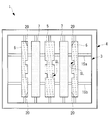
- a front view of the combustion burner 1 is shown in FIG.
- the combustion burner 1 includes a fuel nozzle 3 located on the inner side and a combustion air supply nozzle 4 surrounding the fuel nozzle 3.
- the combustion air supply nozzle 4 is a flow path through which only secondary air flows, and supplies air so as to go straight into the furnace. That is, the air flowing out from the combustion air supply nozzle 4 flows so as not to cross the fuel gas flowing out from the fuel nozzle 3 in parallel.
- a combustion tertiary air nozzle for supplying combustion air is provided outside the combustion air supply nozzle 4.
- the fuel nozzle 3 has a rectangular cross section when viewed from the front, and a fuel gas in which pulverized coal and air are mixed flows inside.
- the downstream side of the fuel gas flow is simply referred to as the downstream side
- the upstream side of the fuel gas flow is simply referred to as the upstream side.
- a plurality of splitters 5, 6, and 7 are provided, and in this embodiment, five splitters are provided.
- Each of the splitters 5, 6, and 7 is provided with a longitudinal axis extending from the lower wall portion (one wall portion) 3 a side of the fuel nozzle 3 to the opposing upper wall portion (other wall portion) 3 b side.
- each splitter 5, 6, 7 is a vertical splitter provided in the vertical direction.
- the upper and lower ends of each of the splitters 5, 6, 7 are fixed to the wall portion of the fuel nozzle 3 by support members 8.
- the fuel nozzle 3 is provided with a nozzle angle adjusting mechanism that can rotate in the vertical direction together with the splitters 5, 6, and 7.
- the flow of the fuel gas is not largely deflected even if the nozzle angle is adjusted in the vertical direction.
- the splitters 5, 6, and 7 are members having a function of dividing the fuel gas flow, and do not have a function of injecting air from the inside.
- the splitter includes the splitters 5 and 6 with slits provided at both ends in the center and the horizontal direction, and the slitless splitter 7 provided on both sides of the splitter 5 with the center slit. In this way, the slitless splitter 7 is disposed at a position adjacent to the slitted splitters 5 and 6.
- the splitters 5, 6, and 7 include a widened portion 10 whose width increases in the fuel gas flow direction.
- a plate-like portion 11 extending in the vertical direction is provided on the upstream side of the widened portion 10 along the fuel gas flow direction.
- the widened portion 10 has a substantially triangular shape when viewed in cross section as shown in FIG.
- the widened portion 10 of the slitted splitter 5 and the slitless splitter 7 at the center spreads on both sides when viewed in cross section as shown in FIG.
- the widened portion 10 of the slitted splitter 6 located at both ends in the horizontal direction extends toward the center side of the fuel nozzle 3, but does not extend toward the wall portion side of the fuel nozzle 3.
- the air flowing out from the combustion air supply nozzle 4 is the fuel gas flowing between the wall surface of the fuel nozzle 3 and the slitted splitter 6. It does not deflect to the flow side. Thereby, the external ignition which arises on the outer peripheral side of the fuel nozzle 3 can be suppressed.
- the downstream ends 5a and 6a of the slitted splitters 5 and 6 are aligned with the position of the downstream end 3c of the fuel nozzle 3, as shown in FIG.
- the downstream end 7 a of the slitless splitter 7 is provided at a position separated by a predetermined distance S on the upstream side of the downstream ends 5 a and 6 a of the slitted splitters 5 and 6.
- the predetermined distance S is 0.001D or more and 1.0D or less, preferably 0.03D or more and 0.5D or less, more preferably 0.05D or more and 0, where D is the equivalent circular diameter at the opening of the fuel nozzle 3. .3D or less.
- Said lower limit and upper limit are determined from the following viewpoint.
- the distance between the splitters 5 and 6 with slits and the splitter 7 without slits becomes too short, and the advantage of securing the channel cross-sectional area by shifting these splitters cannot be obtained.
- the value exceeds the upper limit value the recirculation region formed by the slitless splitter 7 disappears before the splitters 5 and 6 with slits, and the recirculation region of the splitter 7 with slits from the splitters 5 and 6 with slits.
- the advantage of guiding the fuel gas cannot be obtained.
- the predetermined distance S may be adjusted by moving the slitless splitter 7 positioned on the upstream side in the fuel gas flow direction.
- the width of the downstream end 7a is constant in the direction of the longitudinal axis (vertical axis) of the slitless splitter 7.
- a plurality of slits SL for partially reducing the width of the downstream end 5a are formed in the central slitted splitter 5.
- the center slitted splitter 5 is provided with slits SL on both sides at the same height. By these slits, the wide part W1 and the narrow part W2 are formed in the splitter 5 with slits.
- FIG. 3 shows a specific shape of the slit SL.
- the slit SL is formed by notching the downstream end 5a of the slitted splitter 5 in a U-shape.
- the upper surface SL1 and the lower surface SL2 that form the slit SL are surfaces that deflect the fuel gas flow in the longitudinal axis direction of the splitter 5 (vertical direction in the present embodiment). That is, the fuel gas flow is deflected downward by the upper surface SL1, and the fuel gas flow is deflected upward by the lower surface SL2.
- the slits 6 with slits at both ends are also formed with the same slit SL as the splitter 5 with slits at the both ends.
- the slits SL are provided only on the central side of the fuel nozzle 3. It has been. This is because if the slit SL is provided also on the wall portion side of the fuel nozzle 3, it becomes an ignition surface and there is a risk of external ignition.
- the slit SL is preferably provided at the center in the longitudinal direction of the splitters 5 and 6 so that ignition or flame holding is performed on the center side of the fuel nozzle 3 as much as possible, and the slit SL is not provided at the upper and lower ends.
- L 1 in which the slit SL is provided when the length of the splitters 5 and 6 is L 0 , L 1 / L 0 is 0.8 or less, preferably 0.5 or less.
- rectifying plates 15 for separating the splitters 5, 6, 7 and the wall of the fuel nozzle 3 are provided at the upper and lower ends of the longitudinal axes of the splitters 5, 6, 7. Yes. Therefore, the upper rectifying plate 15 separates the fuel gas flowing on the splitters 5, 6 and 7 side from the fuel gas flowing on the upper wall 3 b side of the fuel nozzle 3. Further, the lower rectifying plate 15 separates the fuel gas flowing on the splitters 5, 6 and 7 side from the fuel gas flowing on the lower wall 3 a side of the fuel nozzle 3.
- the combustion burner 1 of the said structure there exist the following effects.
- Increasing the wet edge length by the slitted splitters 5 and 6 provided with the slit SL improves the flame holding property.
- the slitless splitter 7 has a flame holding function by forming a recirculation region downstream of the widened portion 10, but uses the inclined surface of the widened portion 10 to supply fuel to the adjacent slitted splitters 5, 6. It also has a function as a guiding member for guiding.
- the internal flame holding in the splitters 5 and 6 with slits is further strengthened.
- NOx generated in the burner flame region can be reduced by promoting reduction combustion.
- the fuel gas flow is deflected in the direction of the longitudinal axis of the splitters 5 and 6 by the upper surface SL1 and the lower surface SL2 which are inclined surfaces forming the slit SL, the fuel gas flow can be disturbed also in the longitudinal axis direction, and further the flame holding Performance can be improved.
- the slit SL can be three-dimensionally formed by each surface constituting the slit SL, and the flame holding performance can be improved.
- the area occupied by the widened portion 10 of the splitter is larger than when the splitters 5, 6, and 7 are arranged at the same position in the fuel gas flow direction. Can be reduced.
- the flow rate of the fuel gas toward the downstream side in the flow direction of the fuel gas can be brought close to the combustion speed of the fuel gas toward the upstream side. It can be ignited quickly before flowing into the flame, and the flame holding ability of the flame can be improved.
- Fuel is guided to the recirculation region of the downstream slitted splitters 5 and 6 by the slitless splitter 7 located on the upstream side of the fuel gas flow, and the ignition or flame holding of the downstream slitted splitters 5 and 6 is strengthened. Can do.
- the slitless splitter 7 when mainly having the function of guiding pulverized coal, it is preferable to use the slitless splitter 7.
- the rectifying plate 15 that separates the wall surface side of the fuel nozzle 3 and the splitters 5, 6, and 7, it is possible to suppress external ignition that ignites at the upper and lower ends of the splitters 5, 6, and 7. Ignition or flame holding in can be strengthened.
- the slitless splitter 7 is arranged on the upstream side, and the slitted splitters 5 and 6 are arranged on the downstream side. Conversely, the slitless splitter 7 is arranged on the downstream side, The splitters 5 and 6 with slits may be arranged on the upstream side. This configuration is used in the case of a fuel that is desired to be ignited early, and is ignited early by the upstream slitted splitters 5 and 6, and the slitless splitter is formed in the recirculation region formed by these splitters 5 and 6 with slits. To guide the fuel gas.
- all the splitters may be the slitted splitters 5 and 6.
- the slitted splitters 5 and 6 are adjacent to each other, and the wide portion W1 where the slit SL is not formed is opposed to each other, so that the fuel guided to the wide surface of one splitter is the other splitter. To the downstream side. In this way, since the fuel is guided between the adjacent wide portions W1 that are adjacent to each other, the flame holding is strengthened in both splitters.
- tapered portion is formed by removing the corner portion of the splitter 6, and the rest is the same. Therefore, the same reference numerals are assigned to common configurations, and descriptions thereof are omitted.
- tapered portions (corner removing portions) 20 are formed at the upper and lower corners on the center side of the fuel nozzle 3 of the splitter 6 with slits at both ends.
- the shape of the tapered portion 20 is not limited as long as the corner portion is removed, but as shown in FIG. 6, the apex angles ⁇ 1, ⁇ 2, ⁇ 3 of the three surfaces forming the corner portion are removed.
- any shape is acceptable. Therefore, it may be a flat surface such as a tapered surface, or may be composed of a curved surface.
- two rectifying plates 15a and 15b are provided. Each of the rectifying plates 15a and 15b is provided at a height position that is symmetric from the center position in the height direction of the fuel nozzle 3, and is a plate-like body that extends in the horizontal direction.
- the fuel nozzle 3 is ignited by receiving radiation from the inner peripheral surface side of the fuel nozzle 3 and starting from the corner portion. It is possible to suppress external ignition that occurs at the outer periphery of the.
- the tapered portion (corner removing portion) 20 may be provided in another splitter, that is, the splitter 5 with slit or the splitter 7 without slit.
- the number of splitters is five.
- the present invention is not limited to this, and may be two to four or six or more.
- the number of splitters is designed to be optimal depending on the size of the fuel nozzle.
- the vertical splitter in which the splitters 5, 6, and 7 extend in the vertical direction has been described as an example.
- the splitters 5, 6, and 7 can also be applied to the horizontal splitter in which the splitter extends in the horizontal direction.
- the present invention can be applied.
- pulverized coal was mainly demonstrated as fuel in embodiment mentioned above, it is not limited to this, This invention is applicable also to petroleum coke, a petroleum residue, and biomass fuel (solid form, slurry form). it can.
Landscapes
- Engineering & Computer Science (AREA)
- Chemical & Material Sciences (AREA)
- Combustion & Propulsion (AREA)
- Mechanical Engineering (AREA)
- General Engineering & Computer Science (AREA)
- Physics & Mathematics (AREA)
- Thermal Sciences (AREA)
- Combustion Of Fluid Fuel (AREA)
- Gas Burners (AREA)
Abstract
La présente invention comprend une pluralité de séparateurs (5), (6), (7) situés sur le côté d'extrémité distale à l'intérieur d'une buse à combustible (3) de sorte que les axes longitudinaux des séparateurs (5), (6), (7) s'étendent depuis la partie paroi inférieure (3a) de la buse à combustible (3) jusqu'à la partie paroi supérieure (3b) de la buse à combustible (3), les séparateurs (5), (6), (7) séparant l'écoulement de gaz combustible grâce à des parties élargies de largeur croissante dans la direction de l'écoulement du gaz combustible. Les séparateurs comprennent : des séparateurs à fente (5), (6) dans lesquels des fentes (SL) sont formées pour réduire partiellement la largeur des extrémités en aval de l'écoulement de gaz combustible des parties élargies ; et des séparateurs sans fente (7) positionnés de façon adjacente aux séparateurs à fente (5), (6), les séparateurs sans fente (7) étant configurés de façon que la largeur des extrémités en aval de l'écoulement de gaz combustible des parties élargies soit fixée dans la direction de l'axe longitudinal.
Priority Applications (7)
| Application Number | Priority Date | Filing Date | Title |
|---|---|---|---|
| EP16844082.4A EP3299714A4 (fr) | 2015-09-11 | 2016-08-01 | Brûleur de combustion et chaudière pourvue de celui-ci |
| US15/736,108 US10677457B2 (en) | 2015-09-11 | 2016-08-01 | Combustion burner and boiler equipped with the same |
| KR1020197026894A KR102297896B1 (ko) | 2015-09-11 | 2016-08-01 | 연소 버너 및 이것을 구비한 보일러 |
| MX2017016352A MX2017016352A (es) | 2015-09-11 | 2016-08-01 | Quemador de combustion y caldera equipada con el mismo. |
| CN201680037949.6A CN107709881B (zh) | 2015-09-11 | 2016-08-01 | 燃烧器及具备该燃烧器的锅炉 |
| KR1020177036865A KR20180010246A (ko) | 2015-09-11 | 2016-08-01 | 연소 버너 및 이것을 구비한 보일러 |
| RU2017145603A RU2682234C1 (ru) | 2015-09-11 | 2016-08-01 | Горелка для сжигания и котел, снабженный данной горелкой |
Applications Claiming Priority (2)
| Application Number | Priority Date | Filing Date | Title |
|---|---|---|---|
| JP2015179764A JP6642912B2 (ja) | 2015-09-11 | 2015-09-11 | 燃焼バーナ及びこれを備えたボイラ |
| JP2015-179764 | 2015-09-11 |
Publications (1)
| Publication Number | Publication Date |
|---|---|
| WO2017043218A1 true WO2017043218A1 (fr) | 2017-03-16 |
Family
ID=58239376
Family Applications (1)
| Application Number | Title | Priority Date | Filing Date |
|---|---|---|---|
| PCT/JP2016/072564 WO2017043218A1 (fr) | 2015-09-11 | 2016-08-01 | Brûleur de combustion et chaudière pourvue de celui-ci |
Country Status (9)
| Country | Link |
|---|---|
| US (1) | US10677457B2 (fr) |
| EP (1) | EP3299714A4 (fr) |
| JP (1) | JP6642912B2 (fr) |
| KR (2) | KR102297896B1 (fr) |
| CN (1) | CN107709881B (fr) |
| CL (1) | CL2017003438A1 (fr) |
| MX (1) | MX2017016352A (fr) |
| RU (1) | RU2682234C1 (fr) |
| WO (1) | WO2017043218A1 (fr) |
Cited By (1)
| Publication number | Priority date | Publication date | Assignee | Title |
|---|---|---|---|---|
| JP2019132565A (ja) * | 2018-02-01 | 2019-08-08 | 三菱日立パワーシステムズ株式会社 | 燃焼バーナ及びボイラ |
Families Citing this family (1)
| Publication number | Priority date | Publication date | Assignee | Title |
|---|---|---|---|---|
| JP7039792B2 (ja) * | 2017-12-21 | 2022-03-23 | 三菱重工業株式会社 | 燃焼バーナ、これを備えたボイラ及び燃焼バーナの組立方法 |
Citations (6)
| Publication number | Priority date | Publication date | Assignee | Title |
|---|---|---|---|---|
| JPS59205510A (ja) * | 1983-04-22 | 1984-11-21 | コンバツシヨン・エンヂニアリング・インコ−ポレ−テツド | バ−ナのノズルチツプ |
| US5483906A (en) * | 1993-10-26 | 1996-01-16 | Rolls-Royce Power Engineering Plc | Relating to solid fuel burners |
| JPH09203505A (ja) * | 1996-01-29 | 1997-08-05 | Babcock Hitachi Kk | 固体燃料用バーナと固体燃焼システム |
| US6089171A (en) * | 1996-07-08 | 2000-07-18 | Combustion Engineering, Inc. | Minimum recirculation flame control (MRFC) pulverized solid fuel nozzle tip |
| JP2009204256A (ja) * | 2008-02-28 | 2009-09-10 | Mitsubishi Heavy Ind Ltd | 微粉炭バーナ |
| US20090277364A1 (en) * | 2008-03-07 | 2009-11-12 | Alstom Technology Ltd | LOW NOx NOZZLE TIP FOR A PULVERIZED SOLID FUEL FURNACE |
Family Cites Families (66)
| Publication number | Priority date | Publication date | Assignee | Title |
|---|---|---|---|---|
| US2360548A (en) | 1944-10-17 | Combustion method | ||
| US766494A (en) | 1902-12-17 | 1904-08-02 | Francis G Crone | Gas and air mixing burner. |
| US1103253A (en) | 1910-10-24 | 1914-07-14 | Horatio S Bennett | Burner. |
| US1887330A (en) | 1929-11-15 | 1932-11-08 | William S Shaw | Gas burner |
| US2149980A (en) | 1937-11-04 | 1939-03-07 | Jr Henry Wilbur Paret | Method and apparatus for controlling furnace combustion |
| US2259010A (en) | 1939-05-24 | 1941-10-14 | William F Doyle | Apparatus for combustion of fluid fuel |
| US2895435A (en) | 1954-03-15 | 1959-07-21 | Combustion Eng | Tilting nozzle for fuel burner |
| US3112988A (en) | 1960-02-26 | 1963-12-03 | Sheil Oil Company | Mixing gases at supersonic velocity |
| US3213919A (en) | 1962-05-14 | 1965-10-26 | Calzolari Roberto | Nozzle apparatus for burning fuel |
| US3209811A (en) | 1963-03-28 | 1965-10-05 | Loftus Engineering Corp | Combination high velocity burner |
| US3823875A (en) | 1973-08-24 | 1974-07-16 | T Bauer | Burner nozzle tip for pulverized coal and method for its production |
| US4284402A (en) | 1979-05-02 | 1981-08-18 | Atlantic Richfield Company | Flame modifier to reduce NOx emissions |
| DE8005891U1 (de) | 1980-03-01 | 1981-10-01 | Joh. Vaillant Gmbh U. Co, 5630 Remscheid | Mit einem gasluftgemisch gespeister vormischbrenner geringer schalleistung |
| JPS599414A (ja) | 1982-07-08 | 1984-01-18 | Babcock Hitachi Kk | 低窒素酸化物燃焼装置 |
| EP0113342B1 (fr) | 1982-07-12 | 1988-09-14 | Combustion Engineering, Inc. | Buse pour bruleur de charbon pulverise |
| JPS5977206A (ja) | 1982-10-25 | 1984-05-02 | Babcock Hitachi Kk | 燃焼装置 |
| US4634054A (en) * | 1983-04-22 | 1987-01-06 | Combustion Engineering, Inc. | Split nozzle tip for pulverized coal burner |
| JPS60103207A (ja) | 1983-11-10 | 1985-06-07 | Mitsubishi Heavy Ind Ltd | コ−ルバ−ナノズル |
| JP2791029B2 (ja) | 1988-02-23 | 1998-08-27 | バブコツク日立株式会社 | 微粉炭バーナ |
| US5292246A (en) | 1988-05-02 | 1994-03-08 | Institut Francais Du Petrole | Burner for the manufacture of synthetic gas comprising a solid element with holes |
| FI98658C (fi) | 1990-03-07 | 1997-07-25 | Hitachi Ltd | Jauhetun hiilen poltin, jauhetun hiilen kattila ja menetelmä polttaa jauhettua hiiltä |
| JP2954659B2 (ja) | 1990-05-21 | 1999-09-27 | バブコツク日立株式会社 | 微粉炭バーナ |
| US5215259A (en) | 1991-08-13 | 1993-06-01 | Sure Alloy Steel Corporation | Replaceable insert burner nozzle |
| US5529000A (en) | 1994-08-08 | 1996-06-25 | Combustion Components Associates, Inc. | Pulverized coal and air flow spreader |
| JPH08135919A (ja) | 1994-11-11 | 1996-05-31 | Babcock Hitachi Kk | 燃焼装置 |
| DE19539246A1 (de) | 1995-10-21 | 1997-04-24 | Asea Brown Boveri | Airblast-Zerstäuberdüse |
| US6003793A (en) | 1995-12-22 | 1999-12-21 | Mann; Jeffrey S. | Boundary layer coal nozzle assembly for steam generation apparatus |
| CN2281479Y (zh) | 1996-11-18 | 1998-05-13 | 浙江大学 | 宽调节比、多煤种、浓稀相煤粉旋流燃烧装置 |
| JP3448190B2 (ja) | 1997-08-29 | 2003-09-16 | 三菱重工業株式会社 | ガスタービンの燃焼器 |
| JPH11281010A (ja) | 1998-03-26 | 1999-10-15 | Babcock Hitachi Kk | 固体燃料燃焼バーナと固体燃料燃焼装置 |
| FR2784449B1 (fr) | 1998-10-13 | 2000-12-29 | Stein Heurtey | Bruleur a combustible fluide notamment pour fours de rechauffage de produits siderurgiques |
| FR2790309B1 (fr) | 1999-02-25 | 2001-05-11 | Stein Heurtey | Perfectionnements apportes aux bruleurs a flamme plate |
| CN2415254Y (zh) | 2000-02-25 | 2001-01-17 | 华中理工大学 | 带整流板的钝体燃烧器 |
| US6579085B1 (en) | 2000-05-05 | 2003-06-17 | The Boc Group, Inc. | Burner and combustion method for the production of flame jet sheets in industrial furnaces |
| CN1407274A (zh) * | 2001-09-05 | 2003-04-02 | 清华同方股份有限公司 | 一种煤粉直流燃烧器 |
| US7163392B2 (en) | 2003-09-05 | 2007-01-16 | Feese James J | Three stage low NOx burner and method |
| US7500849B2 (en) | 2004-01-16 | 2009-03-10 | Air Products And Chemicals, Inc. | Emulsion atomizer nozzle, and burner, and method for oxy-fuel burner applications |
| NO324171B1 (no) | 2006-01-11 | 2007-09-03 | Ntnu Technology Transfer As | Metode for forbrenning av gass, samt gassbrenner |
| FR2899313B1 (fr) | 2006-03-31 | 2008-05-09 | Huau Christian Bernard Louis | Bruleur polyvalent a flamme creuse pour hydrocarbures |
| WO2008038426A1 (fr) | 2006-09-27 | 2008-04-03 | Babcock-Hitachi Kabushiki Kaisha | Brûleur, et équipement de combustion et chaudière comprenant un brûleur |
| US20080206696A1 (en) | 2007-02-28 | 2008-08-28 | Wark Rickey E | Tilt nozzle for coal-fired burner |
| EP1985926B1 (fr) | 2007-04-26 | 2018-09-05 | Mitsubishi Hitachi Power Systems, Ltd. | Équipement de combustion et procédé de combustion |
| WO2008146373A1 (fr) | 2007-05-30 | 2008-12-04 | Taiyo Nippon Sanso Corporation | Brûleur pour la fabrication d'une particule inorganique rendue sphérique |
| CN201228965Y (zh) | 2007-08-06 | 2009-04-29 | 国际壳牌研究有限公司 | 燃烧器 |
| DE202007018718U1 (de) | 2007-08-29 | 2009-05-14 | Siemens Aktiengesellschaft | Kohlenstaubkombinationsbrenner mit integriertem Pilotbrenner |
| US7775791B2 (en) | 2008-02-25 | 2010-08-17 | General Electric Company | Method and apparatus for staged combustion of air and fuel |
| US8104412B2 (en) | 2008-08-21 | 2012-01-31 | Riley Power Inc. | Deflector device for coal piping systems |
| CN201302156Y (zh) | 2008-11-07 | 2009-09-02 | 浙江大学 | 一种外燃式微油点火和超低负荷稳燃煤粉燃烧器 |
| JP5535522B2 (ja) | 2009-05-22 | 2014-07-02 | 三菱重工業株式会社 | 石炭焚ボイラ |
| JP5374404B2 (ja) | 2009-12-22 | 2013-12-25 | 三菱重工業株式会社 | 燃焼バーナおよびこの燃焼バーナを備えるボイラ |
| DE102010004787B4 (de) | 2010-01-16 | 2014-02-13 | Lurgi Gmbh | Verfahren und Brenner zur Herstellung von Synthesegas |
| JP2012122653A (ja) * | 2010-12-07 | 2012-06-28 | Mitsubishi Heavy Ind Ltd | 燃焼バーナ |
| US8915731B2 (en) | 2010-12-30 | 2014-12-23 | L'air Liquide Societe Anonyme Pour L'etude Et L'exploitation Des Procedes Georges Claude | Flameless combustion burner |
| US20130291770A1 (en) | 2011-01-21 | 2013-11-07 | Babcock-Hitachi Kabushiki Kaisha | Solid fuel burner and combustion device using same |
| CN102620291B (zh) | 2011-01-31 | 2014-09-24 | 中国科学院过程工程研究所 | 低氮氧化物排放煤粉解耦燃烧器及煤粉解耦燃烧方法 |
| JP5778499B2 (ja) * | 2011-06-22 | 2015-09-16 | 三菱重工業株式会社 | 固体燃料焚きバーナ及び固体燃料焚きボイラ |
| ES2738321T3 (es) | 2011-04-01 | 2020-01-21 | Mitsubishi Heavy Ind Ltd | Quemador de combustión |
| JP5670804B2 (ja) * | 2011-04-01 | 2015-02-18 | 三菱重工業株式会社 | 燃焼バーナ |
| JP5763389B2 (ja) * | 2011-04-01 | 2015-08-12 | 三菱重工業株式会社 | 燃焼バーナ |
| JP5897363B2 (ja) | 2012-03-21 | 2016-03-30 | 川崎重工業株式会社 | 微粉炭バイオマス混焼バーナ |
| CN202938290U (zh) | 2012-11-05 | 2013-05-15 | 徐州燃控科技股份有限公司 | 一种内燃式兼多通道低氮燃烧器 |
| CN104100969B (zh) | 2013-04-12 | 2017-04-12 | 气体产品与化学公司 | 宽焰氧‑固体燃料喷燃器 |
| CN103267282B (zh) | 2013-06-11 | 2016-05-11 | 牛博申 | 浓淡分离煤粉燃烧器 |
| CN103672883B (zh) | 2013-12-21 | 2017-02-22 | 哈尔滨锅炉厂有限责任公司 | 栅格式旋流燃烧器 |
| CN203718765U (zh) | 2014-02-10 | 2014-07-16 | 四川川锅锅炉有限责任公司 | 一种带三次风低NOx燃烧器 |
| JP5901737B2 (ja) * | 2014-12-18 | 2016-04-13 | 三菱重工業株式会社 | 燃焼バーナ |
-
2015
- 2015-09-11 JP JP2015179764A patent/JP6642912B2/ja active Active
-
2016
- 2016-08-01 US US15/736,108 patent/US10677457B2/en active Active
- 2016-08-01 EP EP16844082.4A patent/EP3299714A4/fr not_active Withdrawn
- 2016-08-01 CN CN201680037949.6A patent/CN107709881B/zh active Active
- 2016-08-01 KR KR1020197026894A patent/KR102297896B1/ko active IP Right Grant
- 2016-08-01 RU RU2017145603A patent/RU2682234C1/ru active
- 2016-08-01 WO PCT/JP2016/072564 patent/WO2017043218A1/fr active Application Filing
- 2016-08-01 MX MX2017016352A patent/MX2017016352A/es unknown
- 2016-08-01 KR KR1020177036865A patent/KR20180010246A/ko active Search and Examination
-
2017
- 2017-12-28 CL CL2017003438A patent/CL2017003438A1/es unknown
Patent Citations (6)
| Publication number | Priority date | Publication date | Assignee | Title |
|---|---|---|---|---|
| JPS59205510A (ja) * | 1983-04-22 | 1984-11-21 | コンバツシヨン・エンヂニアリング・インコ−ポレ−テツド | バ−ナのノズルチツプ |
| US5483906A (en) * | 1993-10-26 | 1996-01-16 | Rolls-Royce Power Engineering Plc | Relating to solid fuel burners |
| JPH09203505A (ja) * | 1996-01-29 | 1997-08-05 | Babcock Hitachi Kk | 固体燃料用バーナと固体燃焼システム |
| US6089171A (en) * | 1996-07-08 | 2000-07-18 | Combustion Engineering, Inc. | Minimum recirculation flame control (MRFC) pulverized solid fuel nozzle tip |
| JP2009204256A (ja) * | 2008-02-28 | 2009-09-10 | Mitsubishi Heavy Ind Ltd | 微粉炭バーナ |
| US20090277364A1 (en) * | 2008-03-07 | 2009-11-12 | Alstom Technology Ltd | LOW NOx NOZZLE TIP FOR A PULVERIZED SOLID FUEL FURNACE |
Non-Patent Citations (1)
| Title |
|---|
| See also references of EP3299714A4 * |
Cited By (3)
| Publication number | Priority date | Publication date | Assignee | Title |
|---|---|---|---|---|
| JP2019132565A (ja) * | 2018-02-01 | 2019-08-08 | 三菱日立パワーシステムズ株式会社 | 燃焼バーナ及びボイラ |
| WO2019150663A1 (fr) * | 2018-02-01 | 2019-08-08 | 三菱日立パワーシステムズ株式会社 | Brûleur à combustion et chaudière |
| CN111656096A (zh) * | 2018-02-01 | 2020-09-11 | 三菱日立电力系统株式会社 | 燃烧炉及锅炉 |
Also Published As
| Publication number | Publication date |
|---|---|
| EP3299714A1 (fr) | 2018-03-28 |
| KR102297896B1 (ko) | 2021-09-03 |
| KR20190108651A (ko) | 2019-09-24 |
| EP3299714A4 (fr) | 2018-07-18 |
| KR20180010246A (ko) | 2018-01-30 |
| JP2017053601A (ja) | 2017-03-16 |
| MX2017016352A (es) | 2018-05-02 |
| CN107709881A (zh) | 2018-02-16 |
| JP6642912B2 (ja) | 2020-02-12 |
| RU2682234C1 (ru) | 2019-03-15 |
| US20180195715A1 (en) | 2018-07-12 |
| US10677457B2 (en) | 2020-06-09 |
| CL2017003438A1 (es) | 2018-04-20 |
| CN107709881B (zh) | 2021-12-28 |
Similar Documents
| Publication | Publication Date | Title |
|---|---|---|
| EP2696139B1 (fr) | Brûleur alimenté en combustible solide et chaudière alimentée en combustible solide | |
| CA2664769C (fr) | Bruleur, et equipement de combustion et chaudiere comprenant un bruleur | |
| JP6408134B2 (ja) | 燃焼バーナ及びボイラ | |
| JP5386230B2 (ja) | 燃料バーナ及び旋回燃焼ボイラ | |
| WO2017043218A1 (fr) | Brûleur de combustion et chaudière pourvue de celui-ci | |
| JP6632841B2 (ja) | 燃焼バーナ及びこれを備えたボイラ | |
| EP2781834B1 (fr) | Brûleur à mazout, unité brûleur à combustible solide et chaudière à combustible solide | |
| JP6382733B2 (ja) | 固体燃料バーナ | |
| JP5566317B2 (ja) | 固体燃料バーナ | |
| WO2016158473A1 (fr) | Brûleur à combustion et chaudière | |
| JP2016156530A (ja) | 燃焼バーナ、ボイラ、及び燃料ガスの燃焼方法 | |
| JP5778499B2 (ja) | 固体燃料焚きバーナ及び固体燃料焚きボイラ | |
| JP6049814B2 (ja) | 固体燃料焚きバーナ及び固体燃料焚きボイラ | |
| JP6797714B2 (ja) | 燃焼装置 | |
| KR102339292B1 (ko) | 저녹스 버너 | |
| JP7295990B1 (ja) | ガスバーナ | |
| JP5344898B2 (ja) | 旋回燃焼ボイラ | |
| JP2019128080A (ja) | 燃焼バーナ及び燃焼装置並びにボイラ | |
| CN112781033A (zh) | 偏置煤粉燃烧器和燃烧系统 |
Legal Events
| Date | Code | Title | Description |
|---|---|---|---|
| 121 | Ep: the epo has been informed by wipo that ep was designated in this application |
Ref document number: 16844082 Country of ref document: EP Kind code of ref document: A1 |
|
| WWE | Wipo information: entry into national phase |
Ref document number: MX/A/2017/016352 Country of ref document: MX |
|
| ENP | Entry into the national phase |
Ref document number: 20177036865 Country of ref document: KR Kind code of ref document: A |
|
| NENP | Non-entry into the national phase |
Ref country code: DE |