WO2017038561A1 - 点火装置 - Google Patents
点火装置 Download PDFInfo
- Publication number
- WO2017038561A1 WO2017038561A1 PCT/JP2016/074523 JP2016074523W WO2017038561A1 WO 2017038561 A1 WO2017038561 A1 WO 2017038561A1 JP 2016074523 W JP2016074523 W JP 2016074523W WO 2017038561 A1 WO2017038561 A1 WO 2017038561A1
- Authority
- WO
- WIPO (PCT)
- Prior art keywords
- circuit
- ignition
- plasma
- energy input
- discharge
- Prior art date
- Legal status (The legal status is an assumption and is not a legal conclusion. Google has not performed a legal analysis and makes no representation as to the accuracy of the status listed.)
- Ceased
Links
Images


Classifications
-
- F—MECHANICAL ENGINEERING; LIGHTING; HEATING; WEAPONS; BLASTING
- F02—COMBUSTION ENGINES; HOT-GAS OR COMBUSTION-PRODUCT ENGINE PLANTS
- F02P—IGNITION, OTHER THAN COMPRESSION IGNITION, FOR INTERNAL-COMBUSTION ENGINES; TESTING OF IGNITION TIMING IN COMPRESSION-IGNITION ENGINES
- F02P23/00—Other ignition
- F02P23/04—Other physical ignition means, e.g. using laser rays
-
- F—MECHANICAL ENGINEERING; LIGHTING; HEATING; WEAPONS; BLASTING
- F02—COMBUSTION ENGINES; HOT-GAS OR COMBUSTION-PRODUCT ENGINE PLANTS
- F02P—IGNITION, OTHER THAN COMPRESSION IGNITION, FOR INTERNAL-COMBUSTION ENGINES; TESTING OF IGNITION TIMING IN COMPRESSION-IGNITION ENGINES
- F02P3/00—Other installations
- F02P3/02—Other installations having inductive energy storage, e.g. arrangements of induction coils
- F02P3/04—Layout of circuits
- F02P3/0407—Opening or closing the primary coil circuit with electronic switching means
- F02P3/0435—Opening or closing the primary coil circuit with electronic switching means with semiconductor devices
- F02P3/0442—Opening or closing the primary coil circuit with electronic switching means with semiconductor devices using digital techniques
-
- F—MECHANICAL ENGINEERING; LIGHTING; HEATING; WEAPONS; BLASTING
- F02—COMBUSTION ENGINES; HOT-GAS OR COMBUSTION-PRODUCT ENGINE PLANTS
- F02P—IGNITION, OTHER THAN COMPRESSION IGNITION, FOR INTERNAL-COMBUSTION ENGINES; TESTING OF IGNITION TIMING IN COMPRESSION-IGNITION ENGINES
- F02P15/00—Electric spark ignition having characteristics not provided for in, or of interest apart from, groups F02P1/00 - F02P13/00 and combined with layout of ignition circuits
- F02P15/02—Arrangements having two or more sparking plugs
-
- F—MECHANICAL ENGINEERING; LIGHTING; HEATING; WEAPONS; BLASTING
- F02—COMBUSTION ENGINES; HOT-GAS OR COMBUSTION-PRODUCT ENGINE PLANTS
- F02P—IGNITION, OTHER THAN COMPRESSION IGNITION, FOR INTERNAL-COMBUSTION ENGINES; TESTING OF IGNITION TIMING IN COMPRESSION-IGNITION ENGINES
- F02P15/00—Electric spark ignition having characteristics not provided for in, or of interest apart from, groups F02P1/00 - F02P13/00 and combined with layout of ignition circuits
- F02P15/08—Electric spark ignition having characteristics not provided for in, or of interest apart from, groups F02P1/00 - F02P13/00 and combined with layout of ignition circuits having multiple-spark ignition, i.e. ignition occurring simultaneously at different places in one engine cylinder or in two or more separate engine cylinders
-
- F—MECHANICAL ENGINEERING; LIGHTING; HEATING; WEAPONS; BLASTING
- F02—COMBUSTION ENGINES; HOT-GAS OR COMBUSTION-PRODUCT ENGINE PLANTS
- F02P—IGNITION, OTHER THAN COMPRESSION IGNITION, FOR INTERNAL-COMBUSTION ENGINES; TESTING OF IGNITION TIMING IN COMPRESSION-IGNITION ENGINES
- F02P15/00—Electric spark ignition having characteristics not provided for in, or of interest apart from, groups F02P1/00 - F02P13/00 and combined with layout of ignition circuits
- F02P15/10—Electric spark ignition having characteristics not provided for in, or of interest apart from, groups F02P1/00 - F02P13/00 and combined with layout of ignition circuits having continuous electric sparks
-
- F—MECHANICAL ENGINEERING; LIGHTING; HEATING; WEAPONS; BLASTING
- F02—COMBUSTION ENGINES; HOT-GAS OR COMBUSTION-PRODUCT ENGINE PLANTS
- F02P—IGNITION, OTHER THAN COMPRESSION IGNITION, FOR INTERNAL-COMBUSTION ENGINES; TESTING OF IGNITION TIMING IN COMPRESSION-IGNITION ENGINES
- F02P17/00—Testing of ignition installations, e.g. in combination with adjusting; Testing of ignition timing in compression-ignition engines
- F02P17/12—Testing characteristics of the spark, ignition voltage or current
-
- F—MECHANICAL ENGINEERING; LIGHTING; HEATING; WEAPONS; BLASTING
- F02—COMBUSTION ENGINES; HOT-GAS OR COMBUSTION-PRODUCT ENGINE PLANTS
- F02P—IGNITION, OTHER THAN COMPRESSION IGNITION, FOR INTERNAL-COMBUSTION ENGINES; TESTING OF IGNITION TIMING IN COMPRESSION-IGNITION ENGINES
- F02P3/00—Other installations
- F02P3/02—Other installations having inductive energy storage, e.g. arrangements of induction coils
- F02P3/04—Layout of circuits
- F02P3/05—Layout of circuits for control of the magnitude of the current in the ignition coil
- F02P3/051—Opening or closing the primary coil circuit with semiconductor devices
- F02P3/053—Opening or closing the primary coil circuit with semiconductor devices using digital techniques
-
- F—MECHANICAL ENGINEERING; LIGHTING; HEATING; WEAPONS; BLASTING
- F02—COMBUSTION ENGINES; HOT-GAS OR COMBUSTION-PRODUCT ENGINE PLANTS
- F02P—IGNITION, OTHER THAN COMPRESSION IGNITION, FOR INTERNAL-COMBUSTION ENGINES; TESTING OF IGNITION TIMING IN COMPRESSION-IGNITION ENGINES
- F02P9/00—Electric spark ignition control, not otherwise provided for
- F02P9/002—Control of spark intensity, intensifying, lengthening, suppression
- F02P9/007—Control of spark intensity, intensifying, lengthening, suppression by supplementary electrical discharge in the pre-ionised electrode interspace of the sparking plug, e.g. plasma jet ignition
-
- F—MECHANICAL ENGINEERING; LIGHTING; HEATING; WEAPONS; BLASTING
- F02—COMBUSTION ENGINES; HOT-GAS OR COMBUSTION-PRODUCT ENGINE PLANTS
- F02P—IGNITION, OTHER THAN COMPRESSION IGNITION, FOR INTERNAL-COMBUSTION ENGINES; TESTING OF IGNITION TIMING IN COMPRESSION-IGNITION ENGINES
- F02P1/00—Installations having electric ignition energy generated by magneto- or dynamo- electric generators without subsequent storage
-
- F—MECHANICAL ENGINEERING; LIGHTING; HEATING; WEAPONS; BLASTING
- F02—COMBUSTION ENGINES; HOT-GAS OR COMBUSTION-PRODUCT ENGINE PLANTS
- F02P—IGNITION, OTHER THAN COMPRESSION IGNITION, FOR INTERNAL-COMBUSTION ENGINES; TESTING OF IGNITION TIMING IN COMPRESSION-IGNITION ENGINES
- F02P17/00—Testing of ignition installations, e.g. in combination with adjusting; Testing of ignition timing in compression-ignition engines
- F02P17/12—Testing characteristics of the spark, ignition voltage or current
- F02P2017/121—Testing characteristics of the spark, ignition voltage or current by measuring spark voltage
-
- F—MECHANICAL ENGINEERING; LIGHTING; HEATING; WEAPONS; BLASTING
- F02—COMBUSTION ENGINES; HOT-GAS OR COMBUSTION-PRODUCT ENGINE PLANTS
- F02P—IGNITION, OTHER THAN COMPRESSION IGNITION, FOR INTERNAL-COMBUSTION ENGINES; TESTING OF IGNITION TIMING IN COMPRESSION-IGNITION ENGINES
- F02P5/00—Advancing or retarding ignition; Control therefor
- F02P5/04—Advancing or retarding ignition; Control therefor automatically, as a function of the working conditions of the engine or vehicle or of the atmospheric conditions
- F02P5/045—Advancing or retarding ignition; Control therefor automatically, as a function of the working conditions of the engine or vehicle or of the atmospheric conditions combined with electronic control of other engine functions, e.g. fuel injection
Definitions
- the present disclosure relates to an ignition device for an internal combustion engine.
- an ignition device for an internal combustion engine including an ignition coil having a primary coil and a secondary coil and an ignition plug connected to the secondary coil.
- energy is input between the electrodes of the spark plug by electromagnetic induction accompanying on / off of energization of the primary coil, and arc discharge is generated in the air-fuel mixture.
- the ignition device includes a plasma device that generates a plasma discharge in an air-fuel mixture, and includes a radical in the air-fuel mixture by generating a plasma discharge to improve the ignitability of the air-fuel mixture (for example, (See Patent Documents 1 and 2).
- ignitability can be improved by including radicals.
- the type and amount of radicals generated by plasma discharge vary depending on the physical state (temperature, pressure, etc.). Therefore, an improvement in ignitability is not necessarily expected even in a lean air-fuel mixture. Therefore, in the lean air-fuel mixture, it is necessary to increase the voltage applied to the spark plug electrode. Therefore, it is necessary to take some measures against the consumption of the electrode of the spark plug even in the ignition device including the plasma device.
- the ignition plug also serves as a plasma device, and the electrode is more consumed.
- This disclosure is intended to suppress consumption of an electrode of a spark plug in an ignition device including a plasma device that generates a plasma discharge in an air-fuel mixture.
- the ignition device of the present disclosure is for an internal combustion engine, and includes an ignition coil having a primary coil and a secondary coil, and an ignition plug connected to the secondary coil. Then, energy is input between the electrodes of the spark plug by electromagnetic induction accompanying on / off of energization to the primary coil, and arc discharge is generated in the air-fuel mixture.
- the ignition device of the present disclosure includes a plasma device, a first circuit, a second circuit, and a control unit, which will be described below.
- the plasma device includes an electrode different from the spark plug, and generates plasma discharge in the air-fuel mixture before generating arc discharge.
- the first circuit causes the spark plug to start arc discharge by turning on and off the energization of the primary coil.
- the second circuit energizes the primary coil in the direction opposite to the energization direction by the first circuit during the arc discharge started by the operation of the first circuit.
- the second circuit maintains the energization direction in the same direction as the energization of the secondary coil in the operation of the first circuit, continues to input energy between the electrodes of the spark plug, and performs arc discharge. Let it continue.
- the control unit controls the operations of the first circuit, the second circuit, and the plasma apparatus.
- the ignition device by providing the first circuit and the second circuit, it is possible to adjust the energy input period between the electrodes of the spark plug, the amount of energy input per unit time, and the like. For this reason, in the ignition device of the present disclosure, it is possible to continue the arc discharge once generated while suppressing the amount of energy input between the electrodes of the spark plug. Thereby, in the ignition device of the present disclosure, it is possible to suppress consumption of the electrode of the spark plug.
- the inventors have studied and studied a case where a plasma apparatus is combined with an ignition apparatus including a first circuit and a second circuit. As a result, the inventors have obtained the following knowledge and found that a synergistic effect more than a simple combination can be obtained with regard to suppression of electrode consumption of the spark plug. Specifically, it was found that when the amount of energy input to the spark plug is constant and plasma discharge is generated in the air-fuel mixture, the amount of generated heat increases as the energy input period is shorter (see FIG. 5).
- the energy input period to the spark plug can be shortened and the amount of energy input can be reduced compared to when plasma discharge is not generated. Therefore, in the ignition device provided with the plasma device, the consumption of the electrode of the ignition plug can be suppressed.
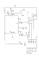
- FIG. 1 is a configuration diagram of an ignition device according to an embodiment.
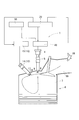
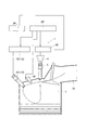
- FIG. 2 is an overall configuration diagram including the ignition device and the internal combustion engine according to the embodiment.
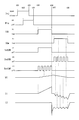
- FIG. 3 is a time chart illustrating the operation of the ignition device according to the embodiment.
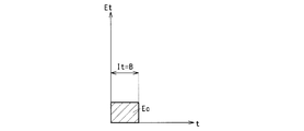
- FIG. 4A is an explanatory diagram of the relationship between the energy input period and the energy input amount under the condition that the energy input amount is constant.
- FIG. 4B is an explanatory diagram of the relationship between the energy input period and the energy input amount under the condition that the energy input amount is constant.
- FIG. 4C is an explanatory diagram of the relationship between the energy input period and the energy input amount under the condition that the energy input amount is constant.
- FIG. 5 is a correlation diagram between the energy input period and the amount of generated heat.
- FIG. 6 is an overall configuration diagram including an ignition device and an internal combustion engine according to a modification.
- FIG. 7 is an overall configuration diagram including an ignition device and an internal combustion engine according to a modification.
- the ignition device 1 is mounted on an internal combustion engine 6 for running a vehicle.
- the ignition device 1 ignites the air-fuel mixture in the combustion chamber 7 at a predetermined ignition timing.
- the ignition device 1 includes an ignition coil 4 having a primary coil 2 and a secondary coil 3, and an ignition plug 5 connected to the secondary coil 3.
- the ignition device 1 supplies energy to the spark plug 5 by electromagnetic induction accompanying on / off of energization to the primary coil 2 to generate arc discharge in the air-fuel mixture.
- the spark plug 5 has a known configuration including a center electrode 8 connected to one end of the secondary coil 3 and a ground electrode 9 that is grounded via a cylinder head or the like of the internal combustion engine 6.
- the spark plug 5 generates arc discharge between the center electrode 8 and the ground electrode 9 by energy generated in the secondary coil 3.
- the center electrode 8 and the ground electrode 9 may be simply referred to as electrodes 8 and 9 when it is not necessary to distinguish between them.
- the internal combustion engine 6 is capable of, for example, lean combustion using gasoline as fuel, and is provided so that a swirling flow of an air-fuel mixture such as a tumble flow or a swirl flow is generated in the combustion chamber 7.
- the ignition device 1 includes a plasma device 10, a first circuit 11, a second circuit 12, a control unit 13, and the like as follows.
- the plasma apparatus 10 has a well-known configuration including a discharge unit 14 and a high voltage high frequency generator 15.
- the discharge unit 14 is provided separately from the spark plug 5, and generates plasma discharge in the air-fuel mixture before generating arc discharge by the spark plug 5.
- the discharge unit 14 includes a center electrode 16 and a ground electrode 17 that is grounded via a cylinder head of the internal combustion engine 6 or the like.
- the discharge unit 14 generates a plasma discharge in the air-fuel mixture by applying a voltage from the high-voltage and high-frequency generator 15 between the center electrode 16 and the ground electrode 17.
- a center electrode 16 and a ground electrode 17 are provided in the combustion chamber 7.
- the high voltage high frequency generator 15 applies an AC voltage according to the command from the controller 13 between the center electrode 16 and the ground electrode 17.
- the center electrode 16 and the ground electrode 17 may be simply referred to as electrodes 16 and 17 when it is not necessary to distinguish between them.
- the fuel injection valve 18 injects fuel.
- the fuel injection valve 18 is provided in an intake passage 19 that guides intake air into the combustion chamber 7.
- the intake passage 19 is upstream of the discharge unit 14 in the air-fuel mixture flow.
- the air-fuel mixture after receiving plasma discharge by the discharge unit 14, reaches the spark plug 5 by, for example, tumble flow and receives arc discharge (see the dotted line in FIG. 2).
- the first circuit 11 causes the spark plug 5 to start arc discharge by turning on and off the energization of the primary coil 2.
- the second circuit 12 energizes the primary coil 2 in the direction opposite to the energization direction by the first circuit 11 during arc discharge started by the operation of the first circuit 11.
- the second circuit 12 maintains the energization direction in the same direction that the energization of the secondary coil 3 was started by the operation of the first circuit 11, and continues to input energy between the electrodes of the spark plug 5.
- the control unit 13 controls operations of the plasma apparatus 10, the first circuit 11, and the second circuit 12.
- the control unit 13 includes an electronic control unit (hereinafter referred to as ECU 20) and a closing driver 21 as described below.
- the ECU20 controls the internal combustion engine 6 whole.
- the ECU 20 controls the energization of the primary coil 2 by outputting various signals such as an ignition signal IGt and a discharge continuation signal IGw described later.
- the ECU 20 controls the electric discharge induced in the secondary coil 3 by controlling the energization to the primary coil 2 to control the arc discharge of the spark plug 5. Further, the ECU 20 controls the plasma discharge by the discharge unit 14 by outputting a control signal to the high voltage high frequency generation unit 15.
- the vehicle is equipped with various sensors that detect parameters indicating the operating state and control state of the internal combustion engine 6.
- the ECU 20 receives signals from these various sensors.
- the ECU 20 includes the following input circuit, CPU, various memories, an output circuit, and the like.
- the input circuit processes the input signal.
- the CPU performs control processing, arithmetic processing, and the like related to the control of the internal combustion engine 6 based on the input signal.
- Various memories store and hold data, programs, and the like necessary for controlling the internal combustion engine 6.
- the output circuit outputs a signal necessary for controlling the internal combustion engine 6 based on the processing result of the CPU.
- Various sensors that output a signal to the ECU 20 are, for example, a rotation speed sensor 24, an intake pressure sensor 25, an air-fuel ratio sensor 26, and the like.
- the rotation speed sensor 24 detects the rotation speed of the internal combustion engine 6.
- the intake pressure sensor 25 detects the pressure of intake air taken into the internal combustion engine 6.
- the air-fuel ratio sensor 26 detects the air-fuel ratio of the air-fuel mixture.
- the ECU 20 executes ignition control by the ignition device 1, plasma discharge control by the plasma device 10, fuel injection control by the fuel injection valve 18, and the like based on detected values of parameters obtained from these various sensors.
- the first circuit 11 is configured to connect the positive electrode of the battery 30 and one terminal of the primary coil 2 and to connect the other terminal of the primary coil 2 to the ground.
- a discharge start switch hereinafter referred to as a first switch 31
- a first switch 31 is disposed on the ground side (low potential side) of the other terminal of the primary coil 2.
- the first circuit 11 stores energy in the primary coil 2 by the on / off operation of the first switch 31. Then, the first circuit 11 uses the energy stored in the primary coil 2 to generate a high voltage in the secondary coil 3 and causes the spark plug 5 to start arc discharge.
- the arc discharge generated by the operation of the first circuit 11 may be referred to as main ignition.
- the energizing direction of the primary coil 2 (the direction of the primary current) is positive in the direction from the battery 30 toward the first switch 31.
- the first circuit 11 turns on the first switch 31 during a period when the ignition signal IGt is given from the ECU 20.
- the first circuit 11 applies the voltage of the battery 30 to the primary coil 2, energizes a positive primary current, and causes the primary coil 2 to store magnetic energy.
- the first circuit 11 turns off the first switch 31 to generate a high voltage in the secondary coil 3 by electromagnetic induction, thereby causing main ignition.
- the first switch 31 is, for example, a power transistor, a MOS transistor, a thyristor, or the like.
- the ignition signal IGt is a signal for instructing a period during which energy is stored in the primary coil 2 and the ignition start timing in the first circuit 11.
- the second circuit 12 is configured to be connected between the primary coil 2 and the first switch 31 with respect to the first circuit 11.
- the second circuit 12 is provided with a switch for turning on / off the power supply from the booster circuit 33 to the primary coil 2 (hereinafter referred to as a second switch 34).
- the booster circuit 33 boosts the voltage of the battery 30 and stores it in the capacitor 36 during a period when the ignition signal IGt is given from the ECU 20.
- the booster circuit 33 includes a capacitor 36, a choke coil 37, a boost switch 38, a boost driver 39, a diode 40, and the like.
- One end of the choke coil 37 is connected to the positive electrode of the battery 30.
- the energization state of the choke coil 37 is interrupted by the boost switch 38.
- the step-up driver 39 gives a control signal to the step-up switch 38 to turn the step-up switch 38 on and off.
- the boost switch 38 is, for example, a MOS transistor.
- the capacitor 36 stores the magnetic energy generated in the choke coil 37 as electrical energy by the on / off operation of the boost switch 38.
- the boost driver 39 repeatedly turns on and off the boost switch 38 at a predetermined period during a period when the ignition signal IGt is given from the ECU 20.
- the diode 40 prevents the energy stored in the capacitor 36 from flowing back to the choke coil 37 side.
- the second circuit 12 includes a second switch 34 and a diode 44.
- the second switch 34 turns on / off the energy input to the primary coil 2 that inputs the energy stored in the capacitor 36 from the minus side of the primary coil 2.
- the second switch 34 is, for example, a MOS transistor.
- the diode 44 prevents the backflow of current from the primary coil 2 to the second switch 34 side.
- the second switch 34 is turned on based on a control signal supplied from the making driver 21, and thereby energizes the negative side of the primary coil 2 from the booster circuit 33.
- the input driver 21 controls the energy input from the capacitor 36 to the primary coil 2 by the on / off operation of the second switch 34 during the period when the discharge continuation signal IGw is given. Thereby, the making driver 21 controls the secondary current that is the energization amount of the secondary coil 3.
- the discharge continuation signal IGw is a signal for instructing a period for continuing the arc discharge generated as the main ignition.
- the second circuit 12 energizes the primary coil 2 in the direction opposite to the energization direction by the first circuit 11 during the arc discharge started by the operation of the first circuit 11.
- the second circuit 12 keeps energizing the secondary current in the same direction as the operation of the first circuit 11 and continues to supply energy between the electrodes of the spark plug 5 to cause arc discharge. Let it continue.
- the arc discharge that continues to the main ignition due to the operation of the second circuit 12 may be referred to as continuous spark discharge.
- the input driver 21 is supplied with a current command signal IGa, which is a signal indicating a command value of the secondary current, from the ECU 20.
- the making driver 21 controls the secondary current based on the supplied current command signal IGa.
- one end of the secondary coil 3 is connected to the center electrode 8 of the spark plug 5.
- the other end of the secondary coil 3 is connected to an F / B circuit 46 that detects a secondary voltage and a secondary current generated in the secondary coil 3 and feeds back to the control unit 13.
- the other end of the secondary coil 3 is connected to the F / B circuit 46 via a diode 47 that limits the direction of the secondary current to one direction.
- the F / B circuit 46 is connected to a shunt resistor 48 for detecting a secondary current.
- the making driver 21 controls the on / off operation of the second switch 34 based on the detected value of the secondary current fed back and the command value of the secondary current specified from the current command signal IGa. For example, the making driver 21 sets threshold values for the upper limit value and the lower limit value for the detection value of the secondary current based on the command value.
- the input driver 21 starts or stops outputting the control signal according to the comparison result between the detected value and the threshold value (upper limit value and lower limit value). Specifically, the input driver 21 stops the output of the control signal when the detected value of the secondary current becomes larger than the upper limit.
- the making driver 21 starts outputting the control signal when the detected value of the secondary current becomes smaller than the lower limit.
- first circuit 11, the second circuit 12, the F / B circuit 46, and the input driver 21 are grouped together as a circuit unit 49.
- the spark plug 5, the ignition coil 4, and the circuit unit 49 are provided in each cylinder.
- the plasma apparatus 10 is also provided in each cylinder.
- the control unit 13 has a control mode for the first circuit 11 and the second circuit 12. Specifically, the control unit 13 has, as control modes, a first mode used when operating the plasma apparatus 10 and a second mode used when not operating the plasma apparatus 10. In the following description, an example when using the first mode is shown.
- “Inj” represents opening / closing of the nozzle hole of the fuel injection valve 18 by open / close
- “Pla” represents the operating state (operation / stop) of the plasma apparatus 10 by on / off
- “IGt” represents the input state of the ignition signal IGt as hi / low
- “IGw” represents the input state of the discharge continuation signal IGw as hi / low
- “1stSW” represents the operation state of the first switch 31 by on / off
- “2ndSW” represents the operation state of the second switch 34 by on / off
- “BstSW” represents the operation of the boost switch 38.
- the state is represented by on / off.
- “VC” represents the charging pressure of the capacitor 36.
- I1 represents a primary current (current value flowing through the primary coil 2)
- “I2” represents a secondary current (current value flowing through the secondary coil 3).
- the fuel injection valve 18 continues to inject and supply fuel from the injection hole until the injection hole is opened and the injection hole is closed (time t01 to time t03). Then, during the period in which the nozzle hole of the fuel injection valve 18 is open (time t01 to time t03), the plasma device 10 starts operation (time t02) and generates plasma in the air-fuel mixture. Even after the fuel supply from the nozzle hole is cut off (after time t03), the plasma apparatus 10 operates for a predetermined period and then stops (time t04).
- the period (time t01 to time t02) from when the nozzle hole of the fuel injection valve 18 is opened to when the operation of the plasma apparatus 10 starts is based on, for example, the separation distance between the fuel injection valve 18 and the discharge unit 14 or the like. Is set.
- a period (time t03 to time t04) from when the nozzle hole of the fuel injection valve 18 is opened to when the operation of the plasma apparatus 10 is stopped is set by the same method.
- the period (time t01 to time t05) from when the injection hole of the fuel injection valve 18 is opened to when the ignition signal IGt is switched from low to high is, for example, the positional relationship between the fuel injection valve 18 and the ignition plug 5 or mixing. It is set based on the swirl flow etc. that occur.
- the first switch 31 maintains the on state (1stSW: on) during the period in which the ignition signal IGt is in the high state (time t05 to time t06). .
- the boost switch 38 is repeatedly turned on / off (BstSW: on / off), and the boosted energy is 36 is stored.
- the first switch 31 is turned off (1stSW: off), and the energization of the primary coil 2 is cut off.
- a high voltage is generated in the secondary coil 3 by electromagnetic induction, and main ignition is generated in the spark plug 5.
- the secondary current I2 attenuates in a substantially triangular wave shape (see the dotted line I2).
- the discharge continuation signal IGw switches from low to high (time t07).
- the second switch 34 When the discharge continuation signal IGw switches from low to high (time t07), the second switch 34 is on / off controlled (2ndSW: on / off). Thereby, the energy stored in the capacitor 36 is sequentially input to the negative side of the primary coil 2, and the primary current I 1 flows from the primary coil 2 toward the positive pole of the battery 30. Specifically, each time the second switch 34 is turned on (2ndSW: on), a current from the primary coil 2 toward the positive pole of the battery 30 is added, and the primary current I1 increases to the negative side. (Time t07 to time t08).
- the secondary current I2 has an upper limit value and a lower limit value. Maintained between.
- the secondary current flows continuously to such an extent that the arc discharge can be maintained by controlling the second switch 34 on and off.
- the continuous spark discharge is maintained in the spark plug 5 when the discharge continuation signal IGw is kept on.
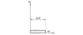
- the energy input by the first circuit 11 and the second circuit 12 is performed in a rectangular shape as shown in FIGS. 4A, 4B, and 4C.
- 4A, 4B, and 4C show the relationship between the energy input period It and the energy input amount under the condition that the energy input amount is constant.
- the vertical axis represents energy input speed Et per unit time
- the horizontal axis represents time t
- the hatched area represents the energy input amount.
- the hatched areas shown in FIGS. 4A, 4B, and 4C are the same, indicating that the amount of energy input is equal. That is, the energy input amount is a constant value Ec.
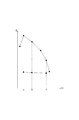
- FIG. 5 shows the correlation between the energy input period It and the amount of heat Q generated by ignition under such a condition that the energy input is a constant value Ec.
- the vertical axis represents the amount of generated heat Q
- the horizontal axis represents the energy input period It.
- Circles in the figure are the amount of heat generated Q obtained during operation of the plasma apparatus 10.
- a triangular mark in the figure is a generated heat quantity Q obtained when the plasma apparatus 10 is not operating as a comparative example.
- A, B, and C in the figure correspond to the energy input periods It in FIGS. 4A, 4B, and 4C, respectively.
- the amount of energy input is a constant value Ec
- the amount of generated heat Q is larger when the plasma apparatus 10 is operating than when the plasma apparatus 10 is not operating.
- the difference in the amount of generated heat Q between when the plasma apparatus 10 is operating and when it is not operating increases as the energy input period It is shortened (in order of C ⁇ B ⁇ A).
- the generated heat quantity Q hardly changes regardless of the length of the energy input period It.
- the amount of generated heat Q increases as the energy input period It is shortened in the order of C ⁇ B ⁇ A.
- the difference in the generated heat quantity Q increases as the energy input period It is shortened.
- the energy input period It can be shortened and the amount of energy input can be reduced compared to when the plasma apparatus 10 is not in operation. Therefore, in the first mode (the mode used when the plasma apparatus 10 operates), the energy input period It by the first circuit 11 and the second circuit 12 is shorter than the second mode (the mode used when the plasma apparatus 10 is not operating). it can. Furthermore, in the first mode, the amount of energy input by the first circuit 11 and the second circuit 12 can be made lower than in the second mode.
- the control unit 13 determines whether or not to operate the plasma apparatus 10. When it is determined that the plasma apparatus 10 is to be operated, the control unit 13 executes the first mode, and when it is determined that the plasma apparatus 10 is not to be operated, the control unit 13 executes the second mode. Whether or not the plasma apparatus 10 is to be operated is determined based on whether or not the plasma apparatus 10 has failed, whether or not the plasma apparatus 10 needs to be used, and the like.
- control unit 13 changes the voltage application frequency between the electrode 16 and the electrode 17 in the plasma apparatus 10 according to the energy input period It and the energy input amount in the first mode. Specifically, the control unit 13 increases the voltage application frequency when, for example, it is desired to reduce the amount of energy input.
- the energy input period It to the spark plug 5 can be shortened and the amount of energy input can be reduced compared to when the plasma device 10 is not operating. Therefore, in the ignition device 1 including the plasma device 10, consumption of the electrodes 8 and 9 in the ignition plug 5 can be suppressed.
- the control unit 13 changes the voltage application frequency between the electrode 16 and the electrode 17 in the plasma device 10 according to the energy input period It and the energy input amount. Therefore, in the ignition device 1, for example, even if the amount of energy input to the primary coil 2 is reduced, the generated heat amount Q can be maintained by increasing the voltage application frequency between the electrodes in the plasma device 10. Therefore, in the ignition device 1 according to the present embodiment, the consumption of the electrode of the spark plug 5 can be further suppressed.
- the ignition device 1 In the ignition device 1 according to the present embodiment, fuel is injected upstream of the electrodes 16 and 17 of the plasma device 10 with respect to the flow of the air-fuel mixture. Thereby, in the ignition device 1, plasma discharge is generated in the fuel, and hydrogen radicals, hydrocarbon radicals, and the like can be generated. Therefore, in the ignition device 1 according to the present embodiment, hydrogen radicals, hydrocarbon radicals, and the like that can further increase the amount of generated heat Q can be used.
- the ignition device of the present disclosure may have various embodiments (modifications) within the technical scope that does not depart from the gist of the invention.
- the discharge unit 14 of the plasma apparatus 10 has the electrodes 16 and 17 provided in the combustion chamber 7, but is not limited thereto.
- the discharge unit 14 may be arranged such that the electrodes 16 and 17 are provided in the intake passage 19.
- the fuel injection valve 18 was provided in the intake passage 19, it is not restricted to this.
- the fuel injection valve 18 may be arranged so that the injection hole is provided in the combustion chamber 7.
- SYMBOLS 1 Ignition device 2 Primary coil 3 Secondary coil 4 Ignition coil 5 Spark plug 6 Internal combustion engine 8 Center electrode (electrode) 9 Ground electrode (electrode) DESCRIPTION OF SYMBOLS 10 Plasma apparatus 11 1st circuit 12 2nd circuit 13 Control part 14 Discharge part 15 High voltage high frequency generation part 16 Center electrode (electrode) 17 Ground electrode (electrode) 18 Fuel injection valve 20 Electronic control unit (ECU) 30 battery 49 circuit unit
Landscapes
- Engineering & Computer Science (AREA)
- Chemical & Material Sciences (AREA)
- Combustion & Propulsion (AREA)
- Mechanical Engineering (AREA)
- General Engineering & Computer Science (AREA)
- Physics & Mathematics (AREA)
- Plasma & Fusion (AREA)
- Optics & Photonics (AREA)
- Ignition Installations For Internal Combustion Engines (AREA)
- Plasma Technology (AREA)
Priority Applications (1)
| Application Number | Priority Date | Filing Date | Title |
|---|---|---|---|
| US15/755,709 US10718310B2 (en) | 2015-08-31 | 2016-08-23 | Ignition apparatus |
Applications Claiming Priority (2)
| Application Number | Priority Date | Filing Date | Title |
|---|---|---|---|
| JP2015-171140 | 2015-08-31 | ||
| JP2015171140A JP2017048701A (ja) | 2015-08-31 | 2015-08-31 | 点火装置 |
Publications (1)
| Publication Number | Publication Date |
|---|---|
| WO2017038561A1 true WO2017038561A1 (ja) | 2017-03-09 |
Family
ID=58187516
Family Applications (1)
| Application Number | Title | Priority Date | Filing Date |
|---|---|---|---|
| PCT/JP2016/074523 Ceased WO2017038561A1 (ja) | 2015-08-31 | 2016-08-23 | 点火装置 |
Country Status (3)
| Country | Link |
|---|---|
| US (1) | US10718310B2 (enExample) |
| JP (1) | JP2017048701A (enExample) |
| WO (1) | WO2017038561A1 (enExample) |
Cited By (1)
| Publication number | Priority date | Publication date | Assignee | Title |
|---|---|---|---|---|
| WO2018203511A1 (ja) * | 2017-05-02 | 2018-11-08 | 国立研究開発法人産業技術総合研究所 | エンジンの着火および燃焼促進技術 |
Families Citing this family (1)
| Publication number | Priority date | Publication date | Assignee | Title |
|---|---|---|---|---|
| JP7196741B2 (ja) * | 2019-04-09 | 2022-12-27 | 株式会社デンソー | 点火制御装置 |
Citations (3)
| Publication number | Priority date | Publication date | Assignee | Title |
|---|---|---|---|---|
| JP2009036125A (ja) * | 2007-08-02 | 2009-02-19 | Nissan Motor Co Ltd | 非平衡プラズマ放電式の点火装置及び点火制御装置 |
| JP2010223189A (ja) * | 2009-03-25 | 2010-10-07 | Toyota Motor Corp | 内燃機関の点火装置 |
| JP2015025397A (ja) * | 2013-07-25 | 2015-02-05 | 株式会社デンソー | 点火装置 |
Family Cites Families (12)
| Publication number | Priority date | Publication date | Assignee | Title |
|---|---|---|---|---|
| JP2007032349A (ja) | 2005-07-25 | 2007-02-08 | Denso Corp | 内燃機関用点火装置 |
| JP4946173B2 (ja) * | 2006-05-17 | 2012-06-06 | 日産自動車株式会社 | 内燃機関 |
| CA2828290C (en) * | 2006-09-20 | 2017-08-08 | Imagineering, Inc. | Ignition device, internal combustion engine, ignition plug, plasma apparatus, exhaust gas decomposition apparatus, ozone generation/sterilization/disinfection apparatus, and deodorization apparatus |
| WO2008156035A1 (ja) * | 2007-06-19 | 2008-12-24 | Ngk Spark Plug Co., Ltd. | プラズマジェット点火プラグおよびその点火装置 |
| JP5119879B2 (ja) * | 2007-11-16 | 2013-01-16 | 日産自動車株式会社 | 内燃機関の非平衡プラズマ放電制御装置及び非平衡プラズマ放電制御方法 |
| JP5015910B2 (ja) * | 2008-03-28 | 2012-09-05 | 株式会社日本自動車部品総合研究所 | 点火装置 |
| JP2010209868A (ja) | 2009-03-12 | 2010-09-24 | Nissan Motor Co Ltd | エンジンの着火制御装置 |
| US9347422B2 (en) * | 2011-01-31 | 2016-05-24 | Imagineering, Inc. | Plasma generation device |
| JP2012140970A (ja) | 2012-04-25 | 2012-07-26 | Nissan Motor Co Ltd | エンジン点火制御装置 |
| JP2013148098A (ja) | 2013-03-13 | 2013-08-01 | Nissan Motor Co Ltd | エンジンの着火制御装置 |
| US10161376B2 (en) | 2013-05-24 | 2018-12-25 | Denso Corporation | Ignition control apparatus |
| JP6445928B2 (ja) * | 2015-05-19 | 2018-12-26 | 本田技研工業株式会社 | 内燃機関の点火装置 |
-
2015
- 2015-08-31 JP JP2015171140A patent/JP2017048701A/ja active Pending
-
2016
- 2016-08-23 WO PCT/JP2016/074523 patent/WO2017038561A1/ja not_active Ceased
- 2016-08-23 US US15/755,709 patent/US10718310B2/en not_active Expired - Fee Related
Patent Citations (3)
| Publication number | Priority date | Publication date | Assignee | Title |
|---|---|---|---|---|
| JP2009036125A (ja) * | 2007-08-02 | 2009-02-19 | Nissan Motor Co Ltd | 非平衡プラズマ放電式の点火装置及び点火制御装置 |
| JP2010223189A (ja) * | 2009-03-25 | 2010-10-07 | Toyota Motor Corp | 内燃機関の点火装置 |
| JP2015025397A (ja) * | 2013-07-25 | 2015-02-05 | 株式会社デンソー | 点火装置 |
Cited By (1)
| Publication number | Priority date | Publication date | Assignee | Title |
|---|---|---|---|---|
| WO2018203511A1 (ja) * | 2017-05-02 | 2018-11-08 | 国立研究開発法人産業技術総合研究所 | エンジンの着火および燃焼促進技術 |
Also Published As
| Publication number | Publication date |
|---|---|
| US10718310B2 (en) | 2020-07-21 |
| US20180340506A1 (en) | 2018-11-29 |
| JP2017048701A (ja) | 2017-03-09 |
Similar Documents
| Publication | Publication Date | Title |
|---|---|---|
| US10371117B2 (en) | Ignition apparatus for internal combustion engine | |
| JP6372140B2 (ja) | 点火装置 | |
| WO2015156371A1 (ja) | 制御装置及び点火装置 | |
| US9903333B2 (en) | Ignition apparatus for an internal-combustion engine | |
| JP2017036694A (ja) | 点火装置 | |
| JP6337584B2 (ja) | 点火装置 | |
| JP6549901B2 (ja) | 点火装置 | |
| WO2017038561A1 (ja) | 点火装置 | |
| JP2016217190A (ja) | 点火装置 | |
| US9957944B2 (en) | Ignition apparatus for internal combustion engine | |
| JP6622513B2 (ja) | 点火装置 | |
| JP6264166B2 (ja) | 点火装置の故障診断装置、および、点火装置の故障診断方法 | |
| JP6291984B2 (ja) | 内燃機関用点火装置 | |
| JP6467849B2 (ja) | 内燃機関用点火装置 | |
| JP6398272B2 (ja) | 点火装置 | |
| US9212646B2 (en) | Ignition apparatus | |
| JP6265016B2 (ja) | 点火装置 | |
| JP6331614B2 (ja) | 点火制御装置 | |
| JP6330440B2 (ja) | 点火制御装置 | |
| JP6531841B2 (ja) | 点火装置 | |
| JP6273986B2 (ja) | 内燃機関用点火装置 | |
| JP6387659B2 (ja) | 内燃機関用点火装置 | |
| JP2015200259A (ja) | 点火制御装置 | |
| JP2015200262A (ja) | 内燃機関の制御装置 |
Legal Events
| Date | Code | Title | Description |
|---|---|---|---|
| 121 | Ep: the epo has been informed by wipo that ep was designated in this application |
Ref document number: 16841593 Country of ref document: EP Kind code of ref document: A1 |
|
| WWE | Wipo information: entry into national phase |
Ref document number: 15755709 Country of ref document: US |
|
| NENP | Non-entry into the national phase |
Ref country code: DE |
|
| 122 | Ep: pct application non-entry in european phase |
Ref document number: 16841593 Country of ref document: EP Kind code of ref document: A1 |