WO2017038539A1 - 接続強度の測定方法 - Google Patents
接続強度の測定方法 Download PDFInfo
- Publication number
- WO2017038539A1 WO2017038539A1 PCT/JP2016/074433 JP2016074433W WO2017038539A1 WO 2017038539 A1 WO2017038539 A1 WO 2017038539A1 JP 2016074433 W JP2016074433 W JP 2016074433W WO 2017038539 A1 WO2017038539 A1 WO 2017038539A1
- Authority
- WO
- WIPO (PCT)
- Prior art keywords
- measurement
- annular
- rod
- holding
- measuring
- Prior art date
- Legal status (The legal status is an assumption and is not a legal conclusion. Google has not performed a legal analysis and makes no representation as to the accuracy of the status listed.)
- Ceased
Links
Images







Classifications
-
- G—PHYSICS
- G01—MEASURING; TESTING
- G01N—INVESTIGATING OR ANALYSING MATERIALS BY DETERMINING THEIR CHEMICAL OR PHYSICAL PROPERTIES
- G01N3/00—Investigating strength properties of solid materials by application of mechanical stress
- G01N3/02—Details
- G01N3/04—Chucks
-
- G—PHYSICS
- G01—MEASURING; TESTING
- G01N—INVESTIGATING OR ANALYSING MATERIALS BY DETERMINING THEIR CHEMICAL OR PHYSICAL PROPERTIES
- G01N19/00—Investigating materials by mechanical methods
- G01N19/04—Measuring adhesive force between materials, e.g. of sealing tape, of coating
-
- G—PHYSICS
- G01—MEASURING; TESTING
- G01N—INVESTIGATING OR ANALYSING MATERIALS BY DETERMINING THEIR CHEMICAL OR PHYSICAL PROPERTIES
- G01N3/00—Investigating strength properties of solid materials by application of mechanical stress
- G01N3/08—Investigating strength properties of solid materials by application of mechanical stress by applying steady tensile or compressive forces
Definitions
- the present invention relates to a method for measuring the connection strength between two connected members.
- inflators used in automobile airbag devices use a part in which cylindrical members are connected to each other at an opening, and a part in which a cylindrical member and a cup member are connected at an opening.
- connection component consisting of two components for a product
- JP-B No. Japanese Patent No. 4916965 describes an invention of a fixing method for measuring the joint strength between cylindrical parts of an inflator.
- a first aspect of the present invention (hereinafter referred to as “first aspect”) is a method for measuring the connection strength of a measurement object in which a first measurement member and a second measurement member are connected,
- the measurement object is a tube member or a cup member
- the second measurement member that is a tube member or a cup member is connected to each opening side, Step 1 of supporting the axial end direction without fixing the annular end surface of the opening of the second measurement member while fixing the peripheral wall portion of the first measurement member from the outside.
- Step 2 for holding the first measurement member fixed in Step 1 in a hollow state;
- a method for measuring the connection strength of a measurement object comprising the step 3 of separating the first measurement member until the connection portion between the first measurement member and the second measurement member is separated.
- the second aspect of the present invention (hereinafter referred to as “second aspect”) A method of measuring a connection strength of a measurement object in which a first measurement member and a second measurement member are connected using a measurement device,
- the measurement object is The first measurement member that is a cylindrical member or a cup member and the second measurement member that is a cylindrical member or a cup member are connected on the respective opening side,
- the measuring device is It has a holding part that holds the measurement object, and a load part that applies a load in the major axis direction of the measurement object,
- the holding part is A first holding part, a second holding part, a fastening fixture for the first measuring member, and an annular member;
- the first holding body includes a first partial surface portion on which a part of the annular member can be placed, and a first flat portion extending in a vertical direction from the first partial surface portion.
- a fastening fixture for the first measuring member is A first rod-like member having a semi-cylindrical first recess having an annular groove at an intermediate position in the length direction, and a second rod-like member having a semi-columnar second recess having an annular groove at an intermediate position in the length direction And further comprising a fastening means for fastening the first rod-shaped member and the second rod-shaped member to each other,
- the annular member has an annular plate surface portion, an inner peripheral surface and an outer peripheral surface of the annular plate surface portion, The annular plate surface portion can contact the first partial surface portion of the first holding portion and the second partial circle of the second holding portion,
- the inner diameter of the center hole of the annular member is such that the end surface on the opening side of the second measurement member is in contact with the annular plate surface portion,
- the outer diameter of the outer peripheral surface of the annular member is such that when the annular plate surface portion is in contact with the first partial surface portion of the first holding portion and the second partial surface
- Step 2 to fix the measuring member,
- the first rod-like member and the second rod-like member to which the first measurement member is fixed are arranged in a gap between the first holding portion and the second holding portion, and the annular member is the first of the first holding portion.
- Step 3 for contacting the partial surface portion and the second partial surface portion of the second holding portion;
- the cup member or cylindrical member serving as the load portion is placed on the first holding portion and the second holding portion from the outer peripheral surface side, and the opening side of the cup member or cylindrical member is integrated.
- FIG. 1 is an axial cross-sectional view of a measurement target of the measurement method of the present invention.
- FIG. 2 is an exploded perspective view (not including a measurement object) of a measurement apparatus for carrying out the measurement method of the present invention.
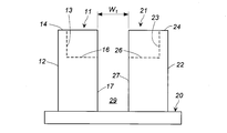
- FIG. 3 is a front view of the first holding unit, the second holding unit, and the substrate unit shown in FIG.
- FIG. 4 is a perspective view of another embodiment of the first holding unit, the second holding unit, and the substrate unit shown in FIG. 5A is a plan view of the fastening fixture shown in FIG. 1 in FIG. 5A
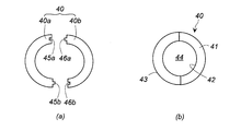
- FIG. 5B is a plan view of the fastening fixture of another embodiment in FIG. 6A is a plan view of another embodiment of the annular member shown in FIG. 2, and FIG.
- FIG. 6B is a plan view illustrating the usage state of FIG. 6A.
- 7A is a front view of a measuring apparatus for carrying out the measuring method of the present invention in FIG. 7A
- FIG. 7B is a plan view of FIG. 7A.
- 8A is a cross-sectional view taken along the line VIII-VIII in FIG. 7B (state before measurement) in FIG. 7A
- FIG. 8B is a cross-sectional view showing the state after measurement in FIG. is there.
- 9A is a cross-sectional view between IX and IX in FIG. 7B (state before measurement) in FIG. 7A
- FIG. 9B is a cross-sectional view showing the state after measurement in FIG. It is.
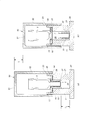
- FIG. 10 is a cross-sectional view in the axial direction (axial direction of the measuring apparatus) for explaining another embodiment of the measuring method of the present invention.
- connection strength such as those in which cylindrical members are connected to each other, and those in which a cylindrical member and a cup member are connected.
- the first measurement member and the second measurement member to be measured are selected from the combination of the cylindrical members, the combination of the cylindrical member and the cup member, and the combination of the cup members, which are connected at each opening side. It has been done. For this reason, the measurement part object of the present invention has a single cylindrical or cylindrical shape having an elongated appearance.
- the cylindrical member and cup member used as a 1st measurement member and a 2nd measurement member although the cross-sectional shape of the width direction (direction orthogonal to a major axis) is general, it is not limited to it, A triangle , Quadrangle (square, rectangle, trapezoid, etc.), oval, etc.
- Both the first measurement member and the second measurement member are made of metal.
- the first measuring member may have a uniform inner diameter and an outer diameter, may be partially different, or may have a through hole, a protrusion, or the like in the peripheral wall portion.
- the second measuring member may have a uniform inner diameter and an outer diameter, may be partially different, or may have a through hole, a protrusion, or the like in the peripheral wall portion.
- the first measurement member and the second measurement member may be the same or different.
- connection method of the first measurement member and the second measurement member is not particularly limited.
- the peripheral wall portion on the opening side of the first measurement member is bent outward, and the opening side of the second measurement member is A peripheral wall portion is bent inward and connected so that the respective bent portions are engaged with each other.
- a groove or a recess is formed in one of the measurement member openings, and the other measurement is performed in the groove or the recess.
- the connection by welding is also included.
- the means for fixing the peripheral wall portion of the first measurement member in a state of being surrounded from the outside is not particularly limited, and is clamped and fixed around the first measurement member.
- a method, a method of fixing by pressing with two fixing members from the outside, and the like can be applied.
- a fixing means the thing which has a blade and protrusion which can be made to bite into the surrounding wall part of a 1st measurement member in the surface which contacts the surrounding wall part of a 1st measurement member can be used.
- the fixing means is preferably such that the cross-sectional shape of the portion in contact with the peripheral wall portion of the first measurement member matches the cross-sectional shape in the width direction of the first measurement member.
- the means for supporting the annular end surface of the opening of the second measurement member from the axial direction without fixing is only the annular end surface of the opening without contacting the peripheral wall of the second measurement member. Can be touched.
- the support means one or two or more plate-like members that can abut at least a part of the annular end surface of the opening can be used. When making it contact
- step 2 of the present invention the first measurement member fixed in step 1 is held hollow.
- the measurement object of the present invention has an elongated shape composed of the first measurement member and the second measurement member.
- the first measurement member needs to be separated from the second measurement member. For this reason, it is necessary to hold
- FIG. 1 As a means for holding in the hollow used in Step 2, a combination of two molded bodies opposed to each other with a gap and the above-described support means can be used.
- As said 2 molded object molded objects, such as a semi-cylinder and a square column which have a plane part for supporting the said support means, can be used.
- the outer shape of the molded body can be determined according to the cross-sectional shape of the measurement target in the width direction.
- the first measuring member and the fixing means are placed in the gap between the two molded bodies by spanning the support means over the two molded bodies. Can be held.
- step 3 of the present invention the first measurement member is pulled apart until the connection portion between the first measurement member and the second measurement member is separated.
- the pulling direction of the first measuring member may be any of a vertical direction, a horizontal direction, and an oblique direction.
- the separating means in step 3 is a means for applying a load to the fixing means for fixing the first measuring member and separating it, so that a uniform load can be applied to the whole fixing means. That's fine.
- the fixing means has a rod-like (or elongated plate-like) shape, means capable of applying a load to the same length position from both ends of the rod-like fixing means is used.
- connection strength of the measurement object composed of the first measurement member and the second measurement member for example, when the peripheral wall portion of the first measurement member is surrounded and fixed from the outside, The peripheral wall is thin, and JP-B No.
- the measurement member is tightened from the outside with movement as in 4916965, it is considered that the first measurement member is deformed at the time of measurement and an accurate connection strength cannot be measured.
- the second measurement member is supported from the axial direction without being fixed at the end face on the opening side, and a load is applied to the first measurement member so as to be separated in the axial direction. Therefore, even if the peripheral wall portion of the first measurement member is thin, the first measurement member is difficult to deform during measurement. For this reason, the connection strength of the measurement object can be accurately measured.
- the outer diameter (d1) of the first measurement member and the inner diameter (d2) of the second measurement member are d2 ⁇ d1, and the peripheral wall of the first measurement member It is preferable that the thickness (t1) of the portion and the thickness (t2) of the peripheral wall portion of the second measurement member satisfy t2 ⁇ t1.
- the opening of the second measurement member connected to the first measurement member has an annular protruding surface protruding radially inward of the opening.
- the outer diameter (d1) of the first measurement member and the inner diameter (d2) of the second measurement member excluding the annular projecting surface are d2 ⁇ d1, and the thickness (t1) of the peripheral wall portion of the first measurement member ) And the thickness (t2) of the peripheral wall portion of the second measurement member excluding the annular projecting surface is t2 ⁇ t1.
- the annular end surface of the second measurement member including the annular projecting surface is supported in the axial direction without being fixed.
- the annular end surface of the opening of the second measuring member is obtained in steps 2 and 3. It becomes easy to support from the axial direction without fixing. Further, by setting t2 ⁇ t1 as described above, the peripheral wall portion of the second measurement member is more difficult to be deformed when the first measurement member is pulled away in step 3.
- the method for measuring the connection strength of the measurement object of the present invention is such that the first measurement member has a flange portion at the opening,
- the second measuring member has an annular wall protruding in an axial direction on an annular end surface of the opening; It is preferable that the flange portion of the first measurement member and the annular wall of the second measurement member are connected by being bent in different directions.
- connection method is a known connection method.
- the flange portion 46 of the cap 44 and the caulking portion 48 of the gas generator housing 32 are used. It is a connection method that is fixed by being caulked (engaged by being bent outward and inward).
- the method of measuring the connection strength of the measurement target according to the first aspect is as follows.
- step 2 After supporting from the axial direction without fixing, by fixing the peripheral wall portion of the first measurement member from the outside by the two rod-shaped fixing means, In step 2, The annular member is spanned over both the first holding member and the second holding member, and the two rod-like fixing means and the first measuring member are hollowed in the gap between the first holding member and the second holding member. Placed in a state where In step 3 above, In the state where the cup member or the cylindrical member is covered from the second measuring member side, and the opening end faces of the cup member or the cylindrical member are brought into contact with both end sides of the two rod-shaped fixing means, A method of pushing the cup member or the cylindrical member until the connection portion of the first measurement member and the second measurement member is separated is preferable.
- the connection strength of the measurement object to which the first measurement member and the second measurement member are connected can be accurately measured.
- the cylindrical member and the cup member that are the first measurement member and the second measurement member that are measurement objects generally have a circular cross-sectional shape in the width direction (direction orthogonal to the long axis), but are not limited thereto. , Triangle, quadrangle (square, rectangle, trapezoid, etc.), ellipse, etc.
- the component parts of the measuring device are adjusted to correspond to the cross-sectional shape in the width direction of the first measuring member and the second measuring member to be measured and the cross-sectional shape in the width direction so as to facilitate measurement. Is preferred.
- the direction in which the load portion is pushed so as to separate the first measurement member from the second measurement member may be any of a vertical direction, a horizontal direction, and an oblique direction.
- the connection strength of the measurement object to which the first measurement member and the second measurement member are connected can be accurately measured.
- the first molded body of the first holding part and the second molded body of the second holding part which are arranged to face each other with the gap
- the planar shape is semicircular
- the first molded body of the first holding part and the second molded body of the second holding part form a circle as a whole including the gap,
- a measurement method in which the centers coincide is preferable.
- the measurement is performed in a state where the centers of the respective members of the measuring device are coincident with each other, and in particular, in step 5, it is possible to apply a force evenly to the first rod-shaped member and the second rod-shaped member. Measurement can be performed.
- the first measurement member is surrounded and fixed from the outside during measurement, and the second measurement member is supported from the axial direction without being fixed.
- the connection strength of the second measurement member is measured. For this reason, since the 2nd measurement member does not change at the time of measurement, the connection strength of the 1st measurement member and the 2nd measurement member can be measured correctly.
- the first measuring member that is a cylindrical member or a cup member and the second measuring member that is a cylindrical member or a cup member are accurately connected to each other on the opening side. Can be measured. For this reason, it is possible to accurately measure the connection strength of the measurement object in various fields, and in particular, it is possible to accurately measure the connection strength of the measurement object used in the gas generator of the airbag device. This is useful in improving the quality of the vessel.
- FIG. 1 shows a measuring object 1 for carrying out the measuring method of the present invention.
- a first measurement member 2 that is a cup member and a second measurement member 5 that is a cylindrical member are connected to each other on the opening side. Both the first measurement member 2 and the second measurement member 5 have a circular cross-sectional shape in the width direction (radial direction).
- the first measurement member (cup member) 2 has a flange portion 3 on the opening 2a side, and a plurality of through holes 4a in the peripheral wall portion 4.
- the second measurement member (tubular member) 5 has a first end opening 5a on the first measurement member 2 side and a second end opening 5b on the opposite side in the axial direction, and the radial direction on the opening 5a side. It has the annular protrusion surface 6 protruded inside.
- the thickness of the annular projecting surface 6 can be made approximately the same as the thickness of the peripheral wall portion 7 excluding the annular projecting surface 6.
- the inner diameter of the annular projecting surface 6 is smaller than the inner diameter of the peripheral wall portion 7 excluding the annular projecting surface 6.
- the annular projecting surface 6 has an annular wall portion 6a projecting in the axial direction on the first measurement member 2 side.
- the outer diameter (d1) of the first measuring member 2 and the inner diameter (d2) of the second measuring member 5 are d2> d1, and the thickness (t1) of the peripheral wall portion 4 of the first measuring member 2 and the second measuring member 5
- the thickness (t2) of the peripheral wall 7 is t2> t1.
- the annular wall portion 6a of the second measurement member 5 is bent inward, and the flange portion 3 of the first measurement member 2 is thickened by the bent portion of the annular wall portion 6a. It is fixed by being sandwiched in the direction.
- the measurement target holding unit includes a first holding unit, a second holding unit, a fastening fixture for the first measurement member, and an annular member.
- the first holding unit 11 and the second holding unit 21 are fixed on the substrate 20.
- the first holding unit 11 includes a first outer peripheral surface (curved surface) 12, a first inner peripheral surface (curved surface) 13, a first arcuate end surface 14 on the opposite side of the substrate 20 in the axial direction, and first side surfaces 14a on both sides. It has the 2nd side surface 14b.
- a first partial circular surface portion 16 is provided on the first inner peripheral surface 13 side, and the first flat portion 17 extends from the first partial circular surface portion 16 to the substrate 20.
- the first plane portion 17 is a vertical plane from the substrate 20.
- the surfaces on which the first side surface 14a, the second side surface 14b, and the first flat surface portion 17 are in contact with each other may be flush with each other.
- the substrate 20 may be formed with bolt holes at the four corners as necessary, and can be fixed to the measurement table with bolts.
- the second holding portion 21 includes a second outer peripheral surface (curved surface) 22, a second inner peripheral surface (curved surface) 23, a second arcuate end surface 24 on the opposite side of the substrate 20 in the axial direction, and first side surfaces 25a on both sides. It has the 2nd side 25b.
- a second partial circular surface portion 26 is provided on the second inner peripheral surface 23 side, and the second flat portion 27 extends from the second partial circular surface portion 26 to the substrate 20.
- the second plane portion 27 is a vertical plane from the substrate 20. The surfaces where the first side surface 25a, the second side surface 25b, and the second flat surface portion 27 are in contact with each other may be flush with each other.
- the first holding part 11 and the second holding part 21 are arranged to face each other with a gap 29 (interval W1) between the first flat part 17 and the second flat part 27.
- the first holding part 11 and the second holding part 21 are arranged so that the planar shape including the gap 29 between the first flat part 17 and the second flat part 27 is circular.
- the first holding unit 111 has a first outer peripheral surface (curved surface) 112, a first flat surface portion 113, and a first partial circular surface portion 114 on the upper surface side.
- the second holding portion 121 has a second outer peripheral surface (curved surface) 122, a second flat surface portion 123, and a second partial circular surface portion 124 on the upper surface side.
- the first holding portion 111 and the second holding portion 121 are connected to the first partial circular surface portion 114 and the second partial circular surface portion 124 on the lower surface side opposite to the axial direction (the connecting portion 120).
- the first holding part 111 and the second holding part 121 are arranged to face each other with a gap 129 (interval W1) between the first flat part 113 and the second flat part 123.
- the first holding part 111 and the second holding part 121 are arranged so that the planar shape including the gap 129 (interval W1) between the first flat part 113 and the second flat part 123 is circular.
- a fastening fixture (bar-shaped fixing means) 30 for the first measuring member 2 shown in FIGS. 2 and 5A is a combination of a first bar-shaped member 31 and a second bar-shaped member 35.
- the first rod member 31 and the second rod member 35 are preferably made of stainless steel or iron.
- the first rod-shaped member 31 has a first main body 32 and a semi-cylindrical first recess 33 at an intermediate position in the length direction of the first main body 32.
- a plurality of annular grooves are formed in the thickness direction on the inner peripheral surface of the first recess 33, and a plurality of annular protrusions 33a are formed between the plurality of annular grooves.
- the annular protrusion 33 a is inclined toward the substrate 20.
- the plurality of annular protrusions 33 a have a triangular cross-sectional shape at the tip, and can be held by being bitten into the peripheral wall 4 of the first measurement member 2.
- the first rod-shaped member 31 has a first through hole 34a and a second through hole 34b on both end sides.
- the thread for example, thread of a female thread
- the thread is formed in each internal peripheral surface.
- the second rod-shaped member 35 has a second main body portion 36 and a semi-cylindrical second concave portion 37 at an intermediate position in the length direction of the second main body portion 36.
- a plurality of annular grooves are formed in the thickness direction on the inner peripheral surface of the second recess 37, and a plurality of annular protrusions 37a are formed between the plurality of annular grooves.
- the annular protrusion 37 a is inclined toward the substrate 20.
- the plurality of annular protrusions 37 a have a triangular cross-sectional shape at the tip, and can be held by being bitten into the peripheral wall 4 of the first measurement member 2.
- the second rod-shaped member 35 has a first through hole 38a and a second through hole 38b on both end sides.
- the first concave portion 33 of the first rod-shaped member 31 and the second concave portion 37 of the second rod-shaped member 35 are formed with a cylindrical space 39 when the first rod-shaped member 31 and the second rod-shaped member 35 are combined, and the columnar shape.
- the space 39 is large enough to surround the peripheral wall 4 of the first measurement member 2 from the outside.
- the height of the columnar space 39 is the same as the thickness of the first rod-shaped member 31 and the second rod-shaped member 35, and is smaller than the length of the first measuring member 2.
- the lengths of the first rod-shaped member 31 and the second rod-shaped member 35 are such that the respective through holes protrude out of the circle composed of the first holding portion 11, the second holding portion 21 and the gap 29.
- the first rod-shaped member 31 and the second rod-shaped member 35 When the first rod-shaped member 31 and the second rod-shaped member 35 are combined, the first through-hole 34a of the first rod-shaped member 31 and the first through-hole 38a of the second rod-shaped member 35 have the same center axis, The center axes of the second through hole 34b of the first rod-shaped member and the second through hole 38b of the second rod-shaped member 35 coincide with each other. Therefore, as shown in FIG. 2, the first rod-shaped member 31 and the second rod-shaped member 35 are integrated by screwing a bolt (male screw) 55 and a bolt (male screw) 56 from the second rod-shaped member 35 side. It can be fixed by tightening.
- the first rod-shaped member 31 and the second rod-shaped member 35 are combined and integrated by a bolt (male screw) 55 and a bolt (male screw) 56, the total width W2 of the first rod-shaped member 31 and the second rod-shaped member 35 is the gap 29.
- the gap is adjusted to be slightly smaller than the interval W1 of the (gap 129).
- a fastening fixture 130 shown in FIG. 5B can be used instead of the fastening fixture 30 of the first measurement member 2 shown in FIGS. 2 and 5A.
- the fastening tool 130 is composed of a combination of a first rod-shaped member 131 and a second rod-shaped member 135, and the first rod-shaped member 131 and the second rod-shaped member 135 are fixed by a fixing pin 140 on one end portion side, and the other end portion. The side can be freely opened and closed.
- the first rod-shaped member 131 has a first main body portion 132 and a first concave portion 133 having a semicylindrical shape that is the same as the first concave portion 33 at an intermediate position in the length direction of the first main body portion 132.
- the second rod-shaped member 135 has a first main body portion 136 and a semi-cylindrical second concave portion 137 that is the same as the second concave portion 37 at an intermediate position in the length direction of the first main body portion 136.
- the first rod-shaped member 131 and the second rod-shaped member 135 can be tightened by a combination of a through hole and a bolt in the vicinity of the end opposite to the fixing pin 140 in the same manner as the tightening fixture 30. Tightening means such as a rubber band or a metal band can also be used.
- An annular member 40 shown in FIG. 2 has an annular plate surface portion 41, a center hole 44, and an inner peripheral surface 42 and an outer peripheral surface 43 of the annular plate surface portion 41.
- the annular plate surface portion 41 can abut on the first partial circular surface portion 16 of the first holding portion 11 and the second partial circular surface portion 26 of the second holding portion 21.
- the outer peripheral surface 43 of the annular plate surface portion can be opposed to the first inner peripheral surface (curved surface) 13 and the second inner peripheral surface (curved surface) 23.
- the inner diameter of the center hole 44 of the annular plate surface portion 41 is the same as the interval (W1) between the first holding portion 11 and the second holding portion 21.
- the inner diameter of the center hole 44 of the annular plate surface portion 41 is larger than the outer diameter of the peripheral wall portion 4 of the first measurement member 2.
- the inner diameter of the center hole 44 of the annular plate surface portion 41 is the same as the inner diameter of the peripheral wall portion 7 of the second measurement member 5.
- the annular member 40 is a combination of the first annular member 40a and the second annular member 40b which are divided into two parts in the diameter passing through the center (center of the center hole 44). It can also be used.
- the annular member 40 is the first annular member 40a and the second annular member 40b, in order to allow the first annular member 40a and the second annular member 40b to be closely combined, for example, FIG.
- the connecting portion between the first annular member 40a and the second annular member 40b is the first partial circular surface portion 16 side of the first holding member 11 and the second portion of the second holding portion 21. It is preferable to be located on the circular surface portion 26 side and not on the gap 29 side.
- the second has a cup shape having a bottom surface portion 51, a peripheral wall portion 52, an opening portion 53, and an annular end surface 54 of the opening portion 53, but does not have the bottom surface portion 51.
- a cylindrical shape may be used.
- the shape and size of the peripheral wall portion 52 and the opening portion 53 of the push-down portion 50 are shapes and sizes that can be covered from the outer peripheral surface sides of the first holding portion 11 and the second holding portion 21.
- the width of the annular end face 54 (thickness of the peripheral wall portion 52) is not particularly limited, and can be determined by adjusting the dimensional relationship with other parts. However, from the viewpoint of strength and ease of transmission of the force when pushed down. Is preferably 5 mm or more.
- the push-down portion 50 is preferably made of metal.
- ⁇ Measurement method> A method for measuring the connection strength of the measuring object 1 composed of the first measuring member 2 and the second measuring member 5 shown in FIG. 1 using the above-described measuring apparatus will be described with reference to FIGS.
- step 1 the first concave portion 33 of the first rod-shaped member 31 that is the fastening fixture 30 of the first measuring member 2 and the second concave portion 37 of the second rod-shaped member 35 are close to each other so that a cylindrical space 39 is formed.
- the annular member 40 is disposed on the position including the columnar space 39.
- Step 2 the first measuring member 2 is first passed through the center hole 44 of the annular member 40, and the annular projecting surface 6 on the opening 5a side of the second measuring member 5 (surface on which the annular wall portion 6a is not formed). Is brought into contact with the annular plate surface portion 41 (the annular plate surface portion 41 on the inner peripheral surface 42 side) of the annular member 40, thereby positioning the first measurement member 2 in the columnar space 39 of the fastening fixture 30.
- the annular projecting surface 6 of the second measuring member 5 is merely in contact with the annular plate surface portion 41 of the annular member 40 and is supported from the axial direction without being fixed. As described above, since the peripheral wall portion 7 of the second measurement member 5 is not fixed by the fixing means, no force is applied to the peripheral wall portion 7 from the outside even during measurement.
- step 2 the first measuring member 2 in the cylindrical space 39 is fixed by tightening and integrating the first rod-shaped member 31 and the second rod-shaped member 35 with tightening means (bolts) 55 and 56.
- Both the first through-hole 34a of the first rod-shaped member 31 and the first through-hole 38a of the second rod-shaped member 35 are fixed by fastening means (bolts) 55, and the second through-hole 34b of the first rod-shaped member 31 and the second through-hole 34b are fixed.
- Both of the second through holes 38b of the two rod-shaped member 35 are fixed by fastening means (bolts) 42.
- the second measuring member 5 is supported in the axial direction by the annular member 40, and the first measuring member 2 connected to the second measuring member 5 is also supported in the axial direction. Is easy.
- Step 3 As shown in FIGS. 8A and 9A, in step 3, the substrate 20 (the first holding unit 11 and the second holding unit 21) is placed in the vertical direction on a plane (preferably a horizontal plane) such as a work table.
- the first rod-shaped member 31 and the second rod-shaped member 35 (total width W2) to which the first measurement member 2 is fixed are placed in the gap 29 (interval) between the first holding portion 11 and the second holding portion 21. W1) and the annular member 40 is brought into contact with the first partial circular surface portion 16 of the first holding portion 11 and the second partial circular surface portion 26 of the second holding portion 21.
- the outer peripheral surface 43 of the annular member 40 is opposed to the first inner peripheral surface (curved surface) 13 and the second inner peripheral surface (curved surface) 23 with a slight gap.
- the substrate 20 can be fixed to the measuring table with bolts.
- the first rod-like member 31 and the second rod-like member 35 are temporarily fixed with a rubber band or the like, and in step 3, the gap 29 (interval) between the first holding portion 11 and the second holding portion 21 is maintained.
- it After being arranged in W1), it may be fixed by tightening with the tightening means 55, 56.
- the second measurement member 5 is also supported from the axial direction.
- the first measurement member 2 connected to the second measurement member 5 and the fastening fixture 30 (the first rod-like member 31 and the second rod-like member 35) for fastening and fixing the first measurement member 2 Is suspended from a gap 29 between the first holding part 11 and the second holding part 21 (that is, held in a hollow state).
- the substrate 20 the first holding unit 11 and the second holding unit 21
- the first measuring member 2 and the fastening fixture 30 are suspended in the vertical direction.
- a push-down portion (cup member) 50 serving as a load portion is placed from the outside of the first outer peripheral surface 12 of the first holding portion 11 and the second outer peripheral surface 22 of the second holding portion 21, so The annular end face 54 of the member 50 is placed on both ends of the fastening fixture 30 (first rod-like member 31 and second rod-like member 35).
- the annular end surface 54 of the push-down portion (cup member) 50 is located at equal intervals from the central axis of the columnar space 39 (first measurement member 2) of the fastening tool 30. For this reason, the center of the 1st measurement member 2, the center of the annular member 40, the center of the 2nd measurement member 5, and the center of the pushing-down part 50 are in the state in which it matched.
- Step 5> As shown in the change from FIG. 8A to FIG. 8B and the change from FIG. 9A to FIG. 9B, the push-down portion 50 is pushed downward (preferably in the vertical direction). At this time, the fastening fixture 30 is pushed down by the push-down portion 50, and the first measurement member 2 fixed by the fastening fixture 30 is also pushed down, but the second measurement member 5 has the first holding portion 11 and the second holding portion 21. Since it is supported from the axial direction by the annular member 40 arranged over the two, the force acts so that the connection portion between the first measurement member 2 and the second measurement member 5 is detached.
- the annular protrusions 33a and 37a are inclined toward the substrate 20, and the peripheral wall portion 4 of the first measurement member 2 is held from the outside at the tip thereof. For this reason, the first measurement member 2 and the second measurement member 5 are separated by pushing down the push-down portion 50, and the connection strength can be obtained from the load applied to the push-down portion 50 when separated.
- the load applied when one or both of the flange portion 3 of the first measurement member 2 and the annular wall portion 6a of the second measurement member 5 is broken or deformed can be used as the connection strength. .
- the first measuring member 2 has the peripheral wall portion 4 fixed uniformly from the outside by the fastening fixture 30 and moves the fastening fastening portion 30 straight in the axial direction. Is difficult to deform except for the flange portion 3. Further, since the second measuring member 5 is supported from the axial direction without being fixed, the second measuring member 5 is not deformed and an accurate connection strength can be measured. Since the measuring method of the present invention has the above characteristics, the connection strength between the first measuring member 2 and the second measuring member 5 can be accurately measured.
- the measuring method of the present invention can also be carried out in a state where the entire measuring device is placed in the lateral direction or the oblique direction.
- the measurement can be performed in a state in which the substrate 20 having bolt holes formed at the four corners is fixed with bolts with respect to a vertical surface or an inclined surface, and measurement is performed using a jig 100 as shown in FIG.
- You can also The measuring apparatus shown in FIG. 10 is obtained by fixing the measuring apparatus in the state of FIG. 9A (that is, also in the state of FIG. 8A) in the horizontal direction (preferably in the horizontal direction).
- tool 100 for fixing a measuring apparatus includes a base portion 101 having a rectangular planar shape, a support wall portion 102 suspended from an intermediate portion in the length direction of the base portion 101, and a lower end side (base portion 101 side) of the support wall portion 102. And a second groove 104 formed on the upper end side of the support wall 102.
- the planar shape of the support wall portion 102 is the same shape as the substrate 20 to which the first holding portion 11 and the second holding portion 21 are fixed.
- the width and length of the first groove portion 103 and the width and length of the second groove portion 104 correspond to the thickness and length of the substrate 20 to which the first holding portion 11 and the second holding portion 21 are fixed.
- the substrate 20 is fixed by being fitted so as to slide with respect to both the first groove portion 103 and the second groove portion 104 of the jig 100.
- the jig 100 shown in FIG. 10 in addition to being able to measure in a state where the measuring device is in the horizontal direction (horizontal direction), by adjusting the angle of the base portion 101 and the support wall portion 102, It is also possible to measure in a state where the measuring device is inclined.
- step 5 the load portion 50 is pushed in the lateral direction (preferably in the horizontal direction), and the first measuring member is changed in the same manner as the change from FIG. 9A to FIG. 9B. 2 and the connection part of the 2nd measurement member 5 are isolate
- the jig 100 is used in FIG. 10, it is also possible to perform measurement by fixing the measuring device by using a work table or a wall surface without using the jig.
- each component of the measuring device used in the measuring method of the present invention can be adjusted to facilitate measurement according to the shape (cross-sectional shape) and size of the measurement target.
Landscapes
- Physics & Mathematics (AREA)
- Health & Medical Sciences (AREA)
- Life Sciences & Earth Sciences (AREA)
- Chemical & Material Sciences (AREA)
- Analytical Chemistry (AREA)
- Biochemistry (AREA)
- General Health & Medical Sciences (AREA)
- General Physics & Mathematics (AREA)
- Immunology (AREA)
- Pathology (AREA)
- Investigating Strength Of Materials By Application Of Mechanical Stress (AREA)
Abstract
Description
自動車のエアバッグ装置に使用されるインフレータには、筒部材同士を開口部において接続した部品、筒部材とカップ部材を開口部において接続した部品が使用されているものがある。
このような二つの部品からなる接続部品を製品に使用するときには、品質管理の観点から、前記接続部品の接続強度を測定する必要がある。
JP-B No.4916965には、インフレータの筒状部品同士の接合強度を測定するための固定方法の発明が記載されている。
本発明の第1の態様(以下「第1の態様」という)は、第1測定部材と第2測定部材が接続された測定対象の接続強度を測定する方法であって、
前記測定対象が、筒部材またはカップ部材である前記第1測定部材と、筒部材またはカップ部材である前記第2測定部材が、それぞれの開口部側で接続されたものであり、
前記第1測定部材の周壁部を外側から包囲した状態で固定しながら、前記第2測定部材の開口部の環状端面を固定しないで軸方向から支持するステップ1、
ステップ1にて固定した前記第1測定部材を中空に保持するステップ2、
前記第1測定部材と前記第2測定部材の接続部分が分離するまで前記第1測定部材を引き離すステップ3を有している、測定対象の接続強度を測定する方法を提供する。
測定装置を使用して、第1測定部材と第2測定部材が接続された測定対象の接続強度を測定する方法であって、
前記測定対象が、
筒部材またはカップ部材である前記第1測定部材と、筒部材またはカップ部材である前記第2測定部材が、それぞれの開口部側で接続されたものであり、
前記測定装置が、
前記測定対象を保持する保持部と、前記測定対象の長軸方向に荷重を加える荷重部を有しているものであり、
前記保持部が、
第1保持部と第2保持部と、前記第1測定部材の締め付け固定具と、環状部材を有しているものであり、
前記第1保持部が、前記環状部材の一部を載せることができる第1部分面部と、前記第1部分面部から垂直方向に延ばされた第1平面部を有している第1成形体からなり、
前記第2保持部が、前記環状部材の残部を載せることができる第2部分面部と、前記第2部分面部から垂直方向に延ばされた第2平面部を有している第2成形体からなり、
前記第1保持部の第1成形体が有している第1平面部と前記第2保持部の第2成形体が有している第2平面部が、間隔をおいて対向配置されているものであり、
前記第1測定部材の締め付け固定具が、
長さ方向の中間位置に環状溝部を有する半円柱状の第1凹部を有する第1棒状部材と、長さ方向の中間位置に環状溝部を有する半円柱状の第2凹部を有する第2棒状部材の組み合わせからなり、さらに前記第1棒状部材と前記第2棒状部材を互いに締め付けるための締め付け手段を備えているものであり、
前記環状部材が、環状板面部と、前記環状板面部の内周面と外周面を有しているものであり、
前記環状板面部が、第1保持部の第1部分面部と第2保持部の第2部分円形に当接することができ、
前記環状部材の中心穴の内径は、前記第2測定部材の開口部側の端面が前記環状板面部に当接する大きさであり、
前記環状部材の外周面の外径が、前記環状板面部が第1保持部の第1部分面部と第2保持部の第2部分面部に当接されたとき、前記第1保持部と前記第2保持部の外側に飛び出さない大きさのものであり、
前記荷重部が、
前記第1保持部と前記第2保持部のそれぞれの外周面側から被せるカップ部材または筒状部材からなるものであり、
前記測定方法が、
前記第1測定部材の締め付け固定具である第1棒状部材の第1凹部と第2棒状部材の第2凹部を円柱状空間が形成されるように近接させた状態にて、前記円柱状空間を含む位置上に前記環状部材を配置するステップ1、
前記環状部材の中心穴に前記測定対象の第1測定部材を通し、さらに前記測定対象の第2測定部材の開口部の周縁部を前記環状部材の環状板面部に当接支持させることで固定しないで軸方向から支持し、前記円柱状空間内に前記第1測定部材が位置するようにした後、前記第1棒状部材と前記第2棒状部材を締め付け手段で締め付けて一体化することで前記第1測定部材を固定するステップ2、
前記第1測定部材を固定した前記第1棒状部材と前記第2棒状部材を前記第1保持部と前記第2保持部の隙間に配置すると共に、前記環状部材を前記第1保持部の第1部分面部と前記第2保持部の第2部分面部に当接させるステップ3、
前記荷重部となるカップ部材または筒状部材を前記第1保持部と前記第2保持部に外周面側から被せて、前記カップ部材または筒状部材の開口部側を一体化された前記第1棒状部材と前記第2棒状部材の両端部上に置くステップ4、
前記カップ部材または筒状部材を押して、前記第1測定部材と前記第2測定部材が分離したときの強度を測定するステップ5を有している、前記測定対象の接続強度を測定する方法を提供する。
本発明は、筒部材同士を接続したもの、筒部材とカップ部材を接続したものなどの接続強度を測定する方法を提供する。
このため、本発明の測定部対象は、外観は細長い形状の1本の筒状または円柱状のものとなる。
なお、第1測定部材と第2測定部材となる筒部材やカップ部材は、幅方向(長軸に直交する方向)の断面形状が円形のものが一般的であるが、それに限定されず、三角形、四角形(正方形、長方形、台形など)、楕円形などであってもよい。
第1測定部材は、内径および外径が均一なものでもよいし、部分的に異なっているものでもよく、周壁部に貫通孔や突起などを有しているものでもよい。
第2測定部材は、内径および外径が均一なものでもよいし、部分的に異なっているものでもよく、周壁部に貫通孔や突起などを有しているものでもよい。
第1測定部材と第2測定部材は、同一のもの同士であってもよいし、異なっているものであってもよい。
また、固定手段としては、第1測定部材の周壁部と接触する面に、第1測定部材の周壁部に食い込ませることができるような刃や突起を有しているものを使用することができる。
固定手段は、第1測定部材の周壁部と接触する部分の断面形状が、前記第1測定部材の幅方向の断面形状と一致しているものが好ましい。
前記支持手段の一つとしては、少なくとも前記開口部の環状端面の一部に当接できる1または2以上の板状部材を使用することができる。
前記開口部の環状端面全部に当接できるようにするときは、板状部材として、1枚の環状の板部材、または2枚を組み合わせて環状の板部材となるものを使用することができる。
上記したとおり、本発明の測定対象は、第1測定部材と第2測定部材からなる細長い形状のものであり、次のステップ3では第1測定部材を第2測定部材から引き離す必要がある。
このため、ステップ3において第1測定部材を引き離すことができる程度の空間内に固定手段で固定された第1測定部材を保持することが必要になる。
ステップ2で使用する中空に保持する手段としては、隙間をおいて対向配置された2つの成形体と上記した支持手段の組み合わせを使用することができる。
前記2つの成形体としては、前記支持手段を支持するための平面部を有している半円柱、四角柱などの成形体を使用することができる。前記成形体の外形は、測定対象の幅方向の断面形状に応じて決めることができる。
固定手段で固定された第1測定部材を中空に保持する方法としては、前記2つの成形体に上記支持手段を掛け渡すことで、前記2つの成形体間の隙間に第1測定部材と固定手段を保持するようにすることができる。
第1測定部材の引き離し方向は、鉛直方向、水平方向、斜め方向のいずれの方向でもよい。
ステップ3における引き離し手段は、第1測定部材を固定している固定手段に対して荷重を加えて引き離す手段であるため、前記固定手段の全体に対して均一な荷重を加えることができる手段であればよい。
例えば、固定手段が棒状(または細長い板状)のものであれば、前記棒状の固定手段の両端部から同じ長さ位置に対して荷重を加えることができる手段を使用する。
しかし、本発明の測定方法では、第2測定部材は開口部側の端面で固定されることなく軸方向から支持されており、第1測定部材には軸方向に引き離されるように荷重が加えられるため、第1測定部材の周壁部が薄いものであっても、測定時において第1測定部材は変形し難い。
このため、測定対象の接続強度を正確に測定できるようになる。
上記のt2≧t1にすることで、ステップ3において第1測定部材を引き離したときに第2測定部材の周壁部がより変形し難くなる。
前記第1測定部材の外径(d1)と前記第2測定部材の前記環状突出面を除いた部分の内径(d2)がd2≧d1であり、前記第1測定部材の周壁部の厚み(t1)と前記第2測定部材の前記環状突出面を除いた部分の周壁部の厚み(t2)がt2≧t1であり、
前記ステップ2において、前記環状突出面を含む前記第2測定部材の環状端面が固定されないで軸方向に支持されているものが好ましい。
さらに上記のt2≧t1にすることで、ステップ3において第1測定部材を引き離したときに第2測定部材の周壁部がより変形し難くなる。
前記第2測定部材が開口部の環状端面に軸方向に突き出された環状壁を有しており、
前記第1測定部材のフランジ部と前記第2測定部材の環状壁が互いに異なる方向に折り曲げられることにより接続されているものが好ましい。
前記ステップ1で使用する前記第1測定部材の周壁部を外側から包囲した状態で固定する手段が、
長さ方向の中間位置において前記第1測定部材の周壁部を外側から締め付けて固定できる二つの棒状固定手段の組み合わせであり、
前記ステップ1で使用する前記第2測定部材の開口部の環状端面を固定しないで軸方向から支持する手段が、
前記二つの棒状固定手段の長さ方向の中間位置に配置される環状部材であり、前記環状部材が有する穴が前記第1測定部材を通すことができる形状および大きさのものであり、
前記ステップ2で使用するステップ1にて固定した前記第1測定部材を中空に保持する手段が、
前記環状部材を掛け渡すことができるように間隔をおいて対向配置された第1保持部材および第2保持部材であり、
前記ステップ3で使用する、前記第1測定部材と前記第2測定部材の接続部分が分離するまで前記第1測定部材を引き離す手段が、
前記第2測定部材の外側に被せ、かつ前記二つの棒状固定手段の両端部側に開口部端面を当接させることができるカップ部材または筒部材であり、
前記ステップ1においては、
前記二つの棒状固定手段の長さ方向の中間位置に前記環状部材を配置した状態で、前記環状部材の穴に前記第1測定部材を通すことで前記第2測定部材の開口部の環状端面を固定しないで軸方向から支持した後、前記二つの棒状固定手段により前記第1測定部材の周壁部を外側から締め付けて固定して、
前記ステップ2においては、
前記第1保持部材と前記第2保持部材の両方に前記環状部材を掛け渡して、前記第1保持部材と前記第2保持部材の隙間に前記二つの棒状固定手段と前記第1測定部材を中空に保持した状態で配置して、
前記ステップ3においては、
前記カップ部材または前記筒部材を前記第2測定部材側から被せ、前記カップ部材または前記筒部材の開口部端面を前記二つの棒状固定手段の両端部側に当接させた状態で、
前記第1測定部材と前記第2測定部材の接続部分が分離するまで前記カップ部材または前記筒部材を押す方法が好ましい。
測定装置の構成部品は、測定対象である第1測定部材と第2測定部材となる筒部材やカップ部材の幅方向の断面形状に対応させて、測定し易くなるように断面形状を調整することが好ましい。
測定方法では、第2測定部材から第1測定部材を分離させるように荷重部を押す方向(即ち、測定対象の長軸方向)は、鉛直方向、水平方向、斜め方向のいずれの方向でもよい。
本発明の測定方法は、測定時に第1測定部材、および第2測定部材が変形し難いため、第1測定部材と第2測定部材が接続された測定対象の接続強度が正確に測定できる。
前記第1保持部の第1成形体と前記第2保持部の第2成形体が、前記隙間も含めて全体として一つの円を形成しているものであり、
前記一つの円の中心と、前記第1棒状部材と前記第2棒状部材により固定された前記第1測定部材の中心、前記環状部材の中心、前記第2測定部材の中心、および前記荷重部の中心が一致した状態で測定する方法が好ましい。
このため、測定時に第2測定部材が変形することがないため、第1測定部材と第2測定部材の接続強度を正確に測定することができる。
このため、各種分野における前記測定対象の接続強度を正確に測定することができ、特にエアバッグ装置のガス発生器で使用する前記測定対象の接続強度を正確に測定することができるため、ガス発生器の品質向上において有用である。
<測定対象>
図1は、本発明の測定方法を実施するための測定対象1である。
カップ部材である第1測定部材2と筒部材である第2測定部材5が、それぞれの開口部側で接続されている。
第1測定部材2と第2測定部材5は、いずれも幅方向(半径方向)の断面形状が円形である。
第1測定部材(カップ部材)2は、開口部2a側にフランジ部3を有しており、周壁部4には複数の貫通孔4aを有している。
図1では、第2測定部材5の周壁部7の外径が一部異なっている部分があるが、前記外径は均一であってもよい。
環状突出面6の厚さは、環状突出面6を除いた周壁部7の厚さと同程度にすることができる。
環状突出面6の内径は、環状突出面6を除いた周壁部7の内径よりも小さくなっている。
環状突出面6は、第1測定部材2側に軸方向に突き出された環状壁部6aを有している。
第1測定部材2と第2測定部材5は、第2測定部材5の環状壁部6aが内側に折り曲げられ、前記環状壁部6aの折り曲げ部分により第1測定部材2のフランジ部3が厚さ方向に挟み込まれることで固定されている。
図2~図6によって、図1に示す第1測定部材2と第2測定部材5からなる測定対象1の測定方法を実施するために適した測定装置を説明する。
測定対象の保持部は、第1保持部と第2保持部と、第1測定部材の締め付け固定具と、環状部材を有している。
第1保持部11は、第1外周面(湾曲面)12、第1内周面(湾曲面)13、基板20と軸方向反対側の第1円弧状端面14、両側の第1側面14aと第2側面14bを有している。
第1内周面13側には、第1部分円形面部16を有しており、第1部分円形面部16から基板20までは第1平面部17となっている。第1平面部17は、基板20からの垂直面である。第1側面14aと第2側面14bおよび第1平面部17が接している面は、面一となっていてもよい。
基板20は、必要に応じて四隅にボルト孔を形成して、測定台に対してボルトで固定できるようにしてもよい。
第2内周面23側には、第2部分円形面部26を有しており、第2部分円形面部26から基板20までは第2平面部27となっている。第2平面部27は、基板20からの垂直面である。第1側面25aと第2側面25bおよび第2平面部27が接している面は、面一となっていてもよい。
第1保持部11と第2保持部21は、第1平面部17と第2平面部27の間の隙間29も含めた平面形状が、円形になるように配置されている。
第1保持部111は、第1外周面(湾曲面)112、第1平面部113、上面側の第1部分円形面部114を有している。
第2保持部121は、第2外周面(湾曲面)122、第2平面部123、上面側の第2部分円形面部124を有している。
第1保持部111と第2保持部121は、第1部分円形面部114と第2部分円形面部124とは軸方向反対側の下面側において連結されている(連結部120)。
第1保持部111と第2保持部121は、第1平面部113と第2平面部123の間の隙間129(間隔W1)も含めた平面形状が、円形になるように配置されている。
第1棒状部材31と第2棒状部材35は、ステンレスや鉄などからなるものが好ましい。
第1凹部33の内周面には、厚さ方向に複数の環状溝が形成されており、複数の環状溝の間には複数の環状突起33aが形成されている。環状突起33aは、基板20に向かって傾斜している。
複数の環状突起33aは、先端部の断面形状が三角形であり、第1測定部材2の周壁部4に食い込ませて保持できるようになっている。
第1棒状部材31は、両端側に第1貫通孔34a、第2貫通孔34bを有している。第1貫通孔34aと第2貫通孔34bは、それぞれの内周面にねじ山(例えば、雌ねじのねじ山)が形成されている。
第2凹部37の内周面には、厚さ方向に複数の環状溝が形成されており、複数の環状溝の間には複数の環状突起37aが形成されている。環状突起37aは、基板20に向かって傾斜している。
複数の環状突起37aは、先端部の断面形状が三角形であり、第1測定部材2の周壁部4に食い込ませて保持できるようになっている。
第2棒状部材35は、両端側に第1貫通孔38a、第2貫通孔38bを有している。
また円柱状空間39の高さは、第1棒状部材31と第2棒状部材35の厚さと同じであり、第1測定部材2の長さより小さくなっている。
第1棒状部材31と第2棒状部材35の長さは、それぞれの貫通孔が、第1保持部11、第2保持部21および隙間29からなる円の外に飛び出す大きさになっている。
このため、図2に示すように、ボルト(雄ねじ)55とボルト(雄ねじ)56を第2棒状部材35側からねじ込むことで、第1棒状部材31と第2棒状部材35を一体になるように締め付けて固定することができるようになっている。
なお、貫通孔とボルトの組み合わせに代えて、クランプ、ゴムバンド、金属バンドのような公知の締め付け手段を使用することもできる。
第1棒状部材31と第2棒状部材35を合わせてボルト(雄ねじ)55とボルト(雄ねじ)56により一体化したとき、第1棒状部材31と第2棒状部材35の合計幅W2は、隙間29(隙間129)の間隔W1よりも僅かに小さい程度になるように調整されている。
締め付け具130は、第1棒状部材131と第2棒状部材135の組み合わせからなるものであり、第1棒状部材131と第2棒状部材135が一端部側において固定ピン140で固定され、他端部側が開閉自在にされているものである。
第2棒状部材135は、第1本体部136と、第1本体部136の長さ方向の中間位置には、第2凹部37同じ半円柱状の第2凹部137を有している。
第1棒状部材131と第2棒状部材135は、固定ピン140と反対側の端部近傍において、締め付け固定具30と同様に貫通孔とボルトの組み合わせで締め付けるようにすることができるほか、クランプ、ゴムバンド、金属バンドのような締め付け手段を使用することもできる。
環状板面部41は、第1保持部11の第1部分円形面部16と第2保持部21の第2部分円形面部26に当接することができる。
環状板面部の外周面43は、第1内周面(湾曲面)13と第2内周面(湾曲面)23に対向させることができる。
環状板面部41の中心穴44の内径は、第1保持部11と第2保持部21の間隔(W1)と同じになっている。
環状板面部41の中心穴44の内径は、第1測定部材2の周壁部4の外径よりも大きくなっている。
環状板面部41の中心穴44の内径は、第2測定部材5の周壁部7の内径と同じになっている。
環状部材40は、図6(a)、(b)に示すように、中心(中心穴44の中心)を通る直径において第1環状部材40aと第2環状部材40bに二分割したものを組み合わせて使用することもできる。
環状部材40が第1環状部材40aと第2環状部材40bであるときは、第1環状部材40aと第2環状部材40bがぴったりと組み合わすことができようにするため、例えば、図6(a)に示すように、第1環状部材40aの第1凹部45aと第2環状部材40bの第2凸部46aを嵌め合わせ、第1環状部材40aの第1凸部45bと第2環状部材40bの第2凸部46bを嵌め合わせるようにしてもよい。
この場合、測定装置に取り付けたときに、第1環状部材40aと第2環状部材40bの接続部分は、第1保持部材11の第1部分円形面部16側と第2保持部21の第2部分円形面部26側に位置して、間隙29側に位置しないようにすることが好ましい。
押し下げ部50の周壁部52および開口部53の形状および大きさは、第1保持部11と第2保持部21のそれぞれの外周面側から被せることができる形状および大きさである。
環状端面54の幅(周壁部52の厚み)は特に制限されず、他の部品との寸法関係を調整して決めることができるものであるが、強度と押し下げるときの力の伝達し易さからは、5mm以上であることが好ましい。
押し下げ部50は、金属からなるものが好ましい。
図2、図7~図9によって、上記した測定装置を使用した、図1に示す第1測定部材2と第2測定部材5からなる測定対象1の接続強度の測定方法を説明する。
ステップ1にて、第1測定部材2の締め付け固定具30である第1棒状部材31の第1凹部33と第2棒状部材35の第2凹部37を円柱状空間39が形成されるように近接させた状態にて、円柱状空間39を含む位置上に環状部材40を配置する。
このとき、第1棒状部材31と第2棒状部材35で形成される円柱状空間39の中心と環状部材40の中心穴44の中心を一致させることが好ましいが、ステップ1では少しずれていてもよい。
ステップ2では、最初に環状部材40の中心穴44に第1測定部材2を通し、さらに第2測定部材5の開口部5a側の環状突出面6(環状壁部6aが形成されていない面)を環状部材40の環状板面部41(内周面42側の環状板面部41)に当接させることで、締め付け固定具30の円柱状空間39内に第1測定部材2を位置させる。
第2測定部材5の環状突出面6は、環状部材40の環状板面部41に対して当接されているだけであり、固定されることなく軸方向から支持されている。
このように第2測定部材5の周壁部7が固定手段で固定されていないため、測定時においても周壁部7に対して外側から力が加えられることがない。
第1棒状部材31の第1貫通孔34aと第2棒状部材35の第1貫通孔38aの両方を締め付け手段(ボルト)55で固定して、第1棒状部材31の第2貫通孔34bと第2棒状部材35の第2貫通孔38b両方を締め付け手段(ボルト)42で固定する。
このとき、第2測定部材5が環状部材40で軸方向に支持されており、第2測定部材5と接続された第1測定部材2も軸方向に支持されているため、締め付けて固定する作業は容易である。
図8(a)、図9(a)に示すように、ステップ3では、作業台などの平面(好ましくは水平面)上に基板20(第1保持部11と第2保持部21)を縦方向になるように置いた状態で、第1測定部材2を固定した第1棒状部材31と第2棒状部材35(合計幅W2)を第1保持部11と第2保持部21の隙間29(間隔W1)内に配置すると共に、環状部材40を第1保持部11の第1部分円形面部16と第2保持部21の第2部分円形面部26に当接させる。
このとき、環状部材40の外周面43は、第1内周面(湾曲面)13と第2内周面(湾曲面)23に対して僅かな隙間を空けて対向されている。
またステップ3において、またはステップ1に入る前において、基板20をボルトで測定台に固定することもできる。
なお、ステップ2において第1棒状部材31と第2棒状部材35をゴムバンドなどで仮止めした状態にとどめておき、ステップ3において、第1保持部11と第2保持部21の隙間29(間隔W1)内に配置した後で、締め付け手段55、56で締め付けて固定してもよい。
このように環状部材40が第1保持部11の第1部分円形面部16と第2保持部21の第2部分円形面部26に当接されているため、第2測定部材5も軸方向から支持されており、第2測定部材5と接続されている第1測定部材2と、第1測定部材2を締め付けて固定している締め付け固定具30(第1棒状部材31と第2棒状部材35)は、第1保持部11と第2保持部21の隙間29に吊り下げられた状態(即ち、中空に保持された状態)になっている。
基板20(第1保持部11と第2保持部21)が水平面に置かれている場合には、第1測定部材2と締め付け固定具30は鉛直方向に吊り下げられている。
ステップ4にて、荷重部となる押し下げ部(カップ部材)50を第1保持部11の第1外周面12と第2保持部21の第2外周面22の外側から被せて、押し下げ部(カップ部材)50の環状端面54を締め付け固定具30(第1棒状部材31と第2棒状部材35の両端部上に置く。
押し下げ部(カップ部材)50の環状端面54は、締め付け具30の円柱状空間39(第1測定部材2)の中心軸から等間隔に位置している。
このため、第1測定部材2の中心、環状部材40の中心、第2測定部材5の中心、および押し下げ部50の中心は一致した状態になっている。
図8(a)から図8(b)の変化、図9(a)から図9(b)の変化に示すように、押し下げ部50を下方向(好ましくは鉛直方向)に押し下げていく。
このとき、押し下げ部50により締め付け固定具30が押し下げられ、締め付け固定具30で固定された第1測定部材2も押し下げられるが、第2測定部材5は第1保持部11と第2保持部21にまたがって配置されている環状部材40により軸方向から支持されているため、第1測定部材2と第2測定部材5の接続部分が脱離するように力が作用する。また環状突起33a、37aは基板20へ向かって傾いており、その先端で第1測定部材2の周壁部4を外側から保持している。
このため、押し下げ部50を押し下げることによって第1測定部材2と第2測定部材5が分離されて、分離されたときに押し下げ部50に加えられていた荷重から接続強度を求めることができる。
その他、第1測定部材2のフランジ部3と第2測定部材5の環状壁部6aの一方または両方が、破壊、変形などを発生させたときに掛かっていた荷重を接続強度とすることもできる。
本発明の測定方法は前記特徴を有しているため、第1測定部材2と第2測定部材5の接続強度を正確に測定することができる。
本発明の測定方法は、測定装置全体を横方向または斜め方向に置いた状態で実施することもできる。
例えば、垂直面または傾斜面に対して、四隅にボルト孔が形成された基板20をボルトで固定した状態で測定することができるほか、図10に示すような治具100を使用して測定することもできる。
図10に示す測定装置は、図9(a)の状態(即ち、図8(a)の状態でもある)の測定装置を横方向(好ましくは水平方向)に固定したものである。
治具100は、平面形状が長方形の基台部101、基台部101の長さ方向の中間部分から垂設された支持壁部102、支持壁部102の下端側(基台部101側)に形成された第1溝部103と、支持壁部102の上端側に形成された第2溝部104を有している。
支持壁部102の平面形状は、第1保持部11と第2保持部21が固定された基板20と同一形状である。
第1溝部103の幅と長さ、第2溝部104の幅と長さは、第1保持部11と第2保持部21が固定された基板20の厚さと長さに対応している。
図10に示す治具100を使用することで、測定装置を横方向(水平方向)にした状態で測定することができるほか、基台部101と支持壁部102の角度を調整することで、測定装置を斜め方向にした状態で測定することもできる。
図10に示す状態で測定するときは、ステップ1の前段階にて、基板101を治具100に固定することが好ましい。
図10に示す状態で測定するときは、ステップ5において、荷重部50を横方向(好ましくは水平方向)に押して、図9(a)から図9(b)の変化と同様に第1測定部材2と第2測定部材5の接続部分を分離させる。
図10では治具100を使用しているが、治具を使用することなく、作業台や壁面を利用することで測定装置を固定して測定することもできる。
Claims (7)
- 第1測定部材と第2測定部材が接続された測定対象の接続強度を測定する方法であって、
前記測定対象が、筒部材またはカップ部材である前記第1測定部材と、筒部材またはカップ部材である前記第2測定部材が、それぞれの開口部側で接続されたものであり、
前記第1測定部材の周壁部を外側から包囲した状態で固定しながら、前記第2測定部材の開口部の環状端面を固定しないで軸方向から支持するステップ1、
ステップ1にて固定した前記第1測定部材を中空に保持するステップ2、
前記第1測定部材と前記第2測定部材の接続部分が分離するまで前記第1測定部材を引き離すステップ3を有している、測定対象の接続強度を測定する方法。 - 前記第1測定部材の外径(d1)と前記第2測定部材の内径(d2)がd2≧d1であり、前記第1測定部材の周壁部の厚み(t1)と前記第2測定部材の周壁部の厚み(t2)がt2≧t1である、請求項1記載の測定対象の接続強度を測定する方法。
- 前記第2測定部材の前記第1測定部材と接続されている開口部が、前記開口部の半径方向内側に突き出された環状突出面を有しているものであり、
前記第1測定部材の外径(d1)と前記第2測定部材の前記環状突出面を除いた部分の内径(d2)がd2≧d1であり、前記第1測定部材の周壁部の厚み(t1)と前記第2測定部材の前記環状突出面を除いた部分の周壁部の厚み(t2)がt2≧t1であり、
前記ステップ2において、前記環状突出面を含む前記第2測定部材の環状端面が固定されないで軸方向に支持されている、請求項1記載の測定対象の接続強度を測定する方法。 - 前記第1測定部材が開口部にフランジ部を有しているものであり、
前記第2測定部材が開口部の環状端面に軸方向に突き出された環状壁を有しており、
前記第1測定部材のフランジ部と前記第2測定部材の環状壁が互いに異なる方向に折り曲げられることにより接続されている、請求項1~3のいずれか1項に記載の測定対象の接続強度を測定する方法。 - 前記ステップ1で使用する前記第1測定部材の周壁部を外側から包囲した状態で固定する手段が、
長さ方向の中間位置において前記第1測定部材の周壁部を外側から締め付けて固定できる二つの棒状固定手段の組み合わせであり、
前記ステップ1で使用する前記第2測定部材の開口部の環状端面を固定しないで軸方向から支持する手段が、
前記二つの棒状固定手段の長さ方向の中間位置に配置される環状部材であり、前記環状部材が有する穴が前記第1測定部材を通すことができる形状および大きさのものであり、
前記ステップ2で使用するステップ1にて固定した前記第1測定部材を中空に保持する手段が、
前記環状部材を掛け渡すことができるように間隔をおいて対向配置された第1保持部材および第2保持部材であり、
前記ステップ3で使用する、前記第1測定部材と前記第2測定部材の接続部分が分離するまで前記第1測定部材を引き離す手段が、
前記第2測定部材の外側に被せ、かつ前記二つの棒状固定手段の両端部側に開口部端面を当接させることができるカップ部材または筒部材であり、
前記ステップ1においては、
前記二つの棒状固定手段の長さ方向の中間位置に前記環状部材を配置した状態で、前記環状部材の穴に前記第1測定部材を通すことで前記第2測定部材の開口部の環状端面を固定しないで軸方向から支持した後、前記二つの棒状固定手段により前記第1測定部材の周壁部を外側から締め付けて固定して、
前記ステップ2においては、
前記第1保持部材と前記第2保持部材の両方に前記環状部材を掛け渡して、前記第1保持部材と前記第2保持部材の隙間に前記二つの棒状固定手段と前記第1測定部材を中空に保持した状態で配置して、
前記ステップ3においては、
前記カップ部材または前記筒部材を前記第2測定部材側から被せ、前記カップ部材または前記筒部材の開口部端面を前記二つの棒状固定手段の両端部側に当接させた状態で、
前記第1測定部材と前記第2測定部材の接続部分が分離するまで前記カップ部材または前記筒部材を押す、請求項1~4のいずれか1項に記載の測定対象の接続強度を測定する方法。 - 測定装置を使用して、第1測定部材と第2測定部材が接続された測定対象の接続強度を測定する方法であって、
前記測定対象が、
筒部材またはカップ部材である前記第1測定部材と、筒部材またはカップ部材である前記第2測定部材が、それぞれの開口部側で接続されたものであり、
前記測定装置が、
前記測定対象を保持する保持部と、前記測定対象の長軸方向に荷重を加える荷重部を有しているものであり、
前記保持部が、
第1保持部と第2保持部と、前記第1測定部材の締め付け固定具と、環状部材を有しているものであり、
前記第1保持部が、前記環状部材の一部を載せることができる第1部分面部と、前記第1部分面部から垂直方向に延ばされた第1平面部を有している第1成形体からなり、
前記第2保持部が、前記環状部材の残部を載せることができる第2部分面部と、前記第2部分面部から垂直方向に延ばされた第2平面部を有している第2成形体からなり、
前記第1保持部の第1成形体が有している第1平面部と前記第2保持部の第2成形体が有している第2平面部が、間隔をおいて対向配置されているものであり、
前記第1測定部材の締め付け固定具が、
長さ方向の中間位置に環状溝部を有する半円柱状の第1凹部を有する第1棒状部材と、長さ方向の中間位置に環状溝部を有する半円柱状の第2凹部を有する第2棒状部材の組み合わせからなり、さらに前記第1棒状部材と前記第2棒状部材を互いに締め付けるための締め付け手段を備えているものであり、
前記環状部材が、環状板面部と、前記環状板面部の内周面と外周面を有しているものであり、
前記環状板面部が、第1保持部の第1部分面部と第2保持部の第2部分円形に当接することができ、
前記環状部材の中心穴の内径は、前記第2測定部材の開口部側の端面が前記環状板面部に当接する大きさであり、
前記環状部材の外周面の外径が、前記環状板面部が第1保持部の第1部分面部と第2保持部の第2部分面部に当接されたとき、前記第1保持部と前記第2保持部の外側に飛び出さない大きさのものであり、
前記荷重部が、
前記第1保持部と前記第2保持部のそれぞれの外周面側から被せるカップ部材または筒状部材からなるものであり、
前記測定方法が、
前記第1測定部材の締め付け固定具である第1棒状部材の第1凹部と第2棒状部材の第2凹部を円柱状空間が形成されるように近接させた状態にて、前記円柱状空間を含む位置上に前記環状部材を配置するステップ1、
前記環状部材の中心穴に前記測定対象の第1測定部材を通し、さらに前記測定対象の第2測定部材の開口部の周縁部を前記環状部材の環状板面部に当接支持させることで固定しないで軸方向から支持し、前記円柱状空間内に前記第1測定部材が位置するようにした後、前記第1棒状部材と前記第2棒状部材を締め付け手段で締め付けて一体化することで前記第1測定部材を固定するステップ2、
前記第1測定部材を固定した前記第1棒状部材と前記第2棒状部材を前記第1保持部と前記第2保持部の隙間に配置すると共に、前記環状部材を前記第1保持部の第1部分面部と前記第2保持部の第2部分面部に当接させるステップ3、
前記荷重部となるカップ部材または筒状部材を前記第1保持部と前記第2保持部に外周面側から被せて、前記カップ部材または筒状部材の開口部側を一体化された前記第1棒状部材と前記第2棒状部材の両端部上に置くステップ4、
前記カップ部材または筒状部材を押して、前記第1測定部材と前記第2測定部材が分離したときの強度を測定するステップ5を有している、前記測定対象の接続強度を測定する方法。 - 前記隙間をおいて対向配置された前記第1保持部の第1成形体と前記第2保持部の第2成形体が、それぞれの平面形状が半円形であり、
前記第1保持部の第1成形体と前記第2保持部の第2成形体が、前記隙間も含めて全体として一つの円を形成しているものであり、
前記一つの円の中心と、前記第1棒状部材と前記第2棒状部材により固定された前記第1測定部材の中心、前記環状部材の中心、前記第2測定部材の中心、および前記荷重部の中心が一致した状態で測定する、請求項6記載の前記測定対象の接続強度を測定する方法。
Priority Applications (4)
| Application Number | Priority Date | Filing Date | Title |
|---|---|---|---|
| CN201680046457.3A CN107923829B (zh) | 2015-09-03 | 2016-08-23 | 连接强度的测定方法 |
| US15/751,256 US10837886B2 (en) | 2015-09-03 | 2016-08-23 | Connection strength measurement method |
| DE112016004022.9T DE112016004022T5 (de) | 2015-09-03 | 2016-08-23 | Verbindungsfestigkeits-messverfahren |
| KR1020187003587A KR20180050281A (ko) | 2015-09-03 | 2016-08-23 | 접속 강도의 측정 방법 |
Applications Claiming Priority (2)
| Application Number | Priority Date | Filing Date | Title |
|---|---|---|---|
| JP2015-173696 | 2015-09-03 | ||
| JP2015173696A JP6499945B2 (ja) | 2015-09-03 | 2015-09-03 | 接続強度の測定方法 |
Publications (1)
| Publication Number | Publication Date |
|---|---|
| WO2017038539A1 true WO2017038539A1 (ja) | 2017-03-09 |
Family
ID=58188515
Family Applications (1)
| Application Number | Title | Priority Date | Filing Date |
|---|---|---|---|
| PCT/JP2016/074433 Ceased WO2017038539A1 (ja) | 2015-09-03 | 2016-08-23 | 接続強度の測定方法 |
Country Status (6)
| Country | Link |
|---|---|
| US (1) | US10837886B2 (ja) |
| JP (1) | JP6499945B2 (ja) |
| KR (1) | KR20180050281A (ja) |
| CN (1) | CN107923829B (ja) |
| DE (1) | DE112016004022T5 (ja) |
| WO (1) | WO2017038539A1 (ja) |
Citations (3)
| Publication number | Priority date | Publication date | Assignee | Title |
|---|---|---|---|---|
| JP2003226219A (ja) * | 2001-11-30 | 2003-08-12 | Daicel Chem Ind Ltd | インフレータ |
| JP2009019989A (ja) * | 2007-07-12 | 2009-01-29 | Daicel Chem Ind Ltd | インフレータの部品の接合強度の測定用治具 |
| JP2013011548A (ja) * | 2011-06-30 | 2013-01-17 | Kurimoto Ltd | 鋳鉄管の接続強度の試験機およびその試験方法 |
Family Cites Families (9)
| Publication number | Priority date | Publication date | Assignee | Title |
|---|---|---|---|---|
| JPS4916965B1 (ja) | 1969-04-05 | 1974-04-26 | ||
| US6289741B1 (en) * | 1999-05-20 | 2001-09-18 | Northrop Grumman Corporation | Molding device and method for measuring the bonding strength of elastomers |
| US7134689B2 (en) | 2001-11-30 | 2006-11-14 | Daicel Chemical Industries, Ltd. | Inflator |
| CN100540513C (zh) * | 2001-11-30 | 2009-09-16 | 大赛璐化学工业株式会社 | 充气器和气囊系统 |
| US20070151360A1 (en) * | 2002-09-20 | 2007-07-05 | Shell Oil Company | Expandable tubular |
| CN201622207U (zh) * | 2010-01-09 | 2010-11-03 | 湖南吉利汽车部件有限公司 | 螺栓拉伸强度试验夹具 |
| CN102768151A (zh) * | 2012-07-31 | 2012-11-07 | 山东送变电工程公司 | 钢丝绳无损卡具 |
| CN203069450U (zh) * | 2013-02-01 | 2013-07-17 | 天津市建筑材料产品质量监督检测中心 | 一种用于脚手架碗扣扣件的横杆接头焊接强度检测的夹具 |
| CN203365238U (zh) * | 2013-08-09 | 2013-12-25 | 武汉钢铁(集团)公司 | 剖分式钢绞线夹具 |
-
2015
- 2015-09-03 JP JP2015173696A patent/JP6499945B2/ja active Active
-
2016
- 2016-08-23 WO PCT/JP2016/074433 patent/WO2017038539A1/ja not_active Ceased
- 2016-08-23 US US15/751,256 patent/US10837886B2/en active Active
- 2016-08-23 KR KR1020187003587A patent/KR20180050281A/ko not_active Withdrawn
- 2016-08-23 CN CN201680046457.3A patent/CN107923829B/zh active Active
- 2016-08-23 DE DE112016004022.9T patent/DE112016004022T5/de not_active Withdrawn
Patent Citations (3)
| Publication number | Priority date | Publication date | Assignee | Title |
|---|---|---|---|---|
| JP2003226219A (ja) * | 2001-11-30 | 2003-08-12 | Daicel Chem Ind Ltd | インフレータ |
| JP2009019989A (ja) * | 2007-07-12 | 2009-01-29 | Daicel Chem Ind Ltd | インフレータの部品の接合強度の測定用治具 |
| JP2013011548A (ja) * | 2011-06-30 | 2013-01-17 | Kurimoto Ltd | 鋳鉄管の接続強度の試験機およびその試験方法 |
Also Published As
| Publication number | Publication date |
|---|---|
| KR20180050281A (ko) | 2018-05-14 |
| US20180246021A1 (en) | 2018-08-30 |
| CN107923829A (zh) | 2018-04-17 |
| JP2017049164A (ja) | 2017-03-09 |
| JP6499945B2 (ja) | 2019-04-10 |
| DE112016004022T5 (de) | 2018-05-17 |
| US10837886B2 (en) | 2020-11-17 |
| CN107923829B (zh) | 2021-06-22 |
Similar Documents
| Publication | Publication Date | Title |
|---|---|---|
| CN103534058B (zh) | 用于将两个构件连接的方法以及构件连接体 | |
| TW201733211A (zh) | 用於測試插座之浮動巢穴 | |
| KR20190026079A (ko) | 파이프에 플랜지를 장착하는 장치 | |
| KR20120079472A (ko) | 고정 부재, 근접 센서, 근접 센서의 장착 구조 및 회동 연결 구조체 및 회동 연결 구조체의 제조 방법 | |
| KR20190026696A (ko) | 파이프에 플랜지를 장착하는 장치 | |
| CN205175603U (zh) | 一种用于螺栓轴力测量的固定装置和螺栓轴力测量装置 | |
| JP6499945B2 (ja) | 接続強度の測定方法 | |
| CN212459163U (zh) | 拉伸夹具及测试系统 | |
| CN104797945B (zh) | 用于电流传感器和/或电压传感器的紧固装置 | |
| CN214237880U (zh) | 夹具及测试系统 | |
| KR101585826B1 (ko) | 부품 검사용 고정장치 | |
| JP2019130576A (ja) | フレア工具 | |
| WO2015156104A1 (ja) | プローブカバー | |
| JP7277914B2 (ja) | フェライトクランプの固定具 | |
| KR20140004567U (ko) | 부재 받침 장치 | |
| KR20160031300A (ko) | 샘플 홀더 | |
| WO2010123149A1 (ja) | 固定具 | |
| US20160082573A1 (en) | Clamps and Clamp Components | |
| KR100665912B1 (ko) | 벨로우즈 고정장치 | |
| JP2010515925A (ja) | パーツ位置決めアセンブリ | |
| JP6007301B1 (ja) | 検査治具 | |
| AU2014100116A4 (en) | Clamps & clamp components | |
| JP2007245316A (ja) | ワーク位置決め装置 | |
| JP5975341B2 (ja) | 表面粗さ測定器用アタッチメント及び表面粗さ測定器 | |
| EP3015023A1 (en) | Constituent device for furniture |
Legal Events
| Date | Code | Title | Description |
|---|---|---|---|
| 121 | Ep: the epo has been informed by wipo that ep was designated in this application |
Ref document number: 16841571 Country of ref document: EP Kind code of ref document: A1 |
|
| ENP | Entry into the national phase |
Ref document number: 20187003587 Country of ref document: KR Kind code of ref document: A |
|
| WWE | Wipo information: entry into national phase |
Ref document number: 15751256 Country of ref document: US |
|
| WWE | Wipo information: entry into national phase |
Ref document number: 112016004022 Country of ref document: DE |
|
| 122 | Ep: pct application non-entry in european phase |
Ref document number: 16841571 Country of ref document: EP Kind code of ref document: A1 |