WO2017038486A1 - 自動車ユーザ情報管理システム - Google Patents
自動車ユーザ情報管理システム Download PDFInfo
- Publication number
- WO2017038486A1 WO2017038486A1 PCT/JP2016/074126 JP2016074126W WO2017038486A1 WO 2017038486 A1 WO2017038486 A1 WO 2017038486A1 JP 2016074126 W JP2016074126 W JP 2016074126W WO 2017038486 A1 WO2017038486 A1 WO 2017038486A1
- Authority
- WO
- WIPO (PCT)
- Prior art keywords
- user information
- user
- information
- vehicle
- information management
- Prior art date
Links
Images


Classifications
-
- A—HUMAN NECESSITIES
- A61—MEDICAL OR VETERINARY SCIENCE; HYGIENE
- A61B—DIAGNOSIS; SURGERY; IDENTIFICATION
- A61B5/00—Measuring for diagnostic purposes; Identification of persons
- A61B5/117—Identification of persons
- A61B5/1171—Identification of persons based on the shapes or appearances of their bodies or parts thereof
- A61B5/1172—Identification of persons based on the shapes or appearances of their bodies or parts thereof using fingerprinting
-
- B—PERFORMING OPERATIONS; TRANSPORTING
- B60—VEHICLES IN GENERAL
- B60R—VEHICLES, VEHICLE FITTINGS, OR VEHICLE PARTS, NOT OTHERWISE PROVIDED FOR
- B60R16/00—Electric or fluid circuits specially adapted for vehicles and not otherwise provided for; Arrangement of elements of electric or fluid circuits specially adapted for vehicles and not otherwise provided for
- B60R16/02—Electric or fluid circuits specially adapted for vehicles and not otherwise provided for; Arrangement of elements of electric or fluid circuits specially adapted for vehicles and not otherwise provided for electric constitutive elements
- B60R16/037—Electric or fluid circuits specially adapted for vehicles and not otherwise provided for; Arrangement of elements of electric or fluid circuits specially adapted for vehicles and not otherwise provided for electric constitutive elements for occupant comfort, e.g. for automatic adjustment of appliances according to personal settings, e.g. seats, mirrors, steering wheel
-
- B—PERFORMING OPERATIONS; TRANSPORTING
- B60—VEHICLES IN GENERAL
- B60W—CONJOINT CONTROL OF VEHICLE SUB-UNITS OF DIFFERENT TYPE OR DIFFERENT FUNCTION; CONTROL SYSTEMS SPECIALLY ADAPTED FOR HYBRID VEHICLES; ROAD VEHICLE DRIVE CONTROL SYSTEMS FOR PURPOSES NOT RELATED TO THE CONTROL OF A PARTICULAR SUB-UNIT
- B60W30/00—Purposes of road vehicle drive control systems not related to the control of a particular sub-unit, e.g. of systems using conjoint control of vehicle sub-units, or advanced driver assistance systems for ensuring comfort, stability and safety or drive control systems for propelling or retarding the vehicle
- B60W30/14—Adaptive cruise control
- B60W30/16—Control of distance between vehicles, e.g. keeping a distance to preceding vehicle
-
- B—PERFORMING OPERATIONS; TRANSPORTING
- B60—VEHICLES IN GENERAL
- B60W—CONJOINT CONTROL OF VEHICLE SUB-UNITS OF DIFFERENT TYPE OR DIFFERENT FUNCTION; CONTROL SYSTEMS SPECIALLY ADAPTED FOR HYBRID VEHICLES; ROAD VEHICLE DRIVE CONTROL SYSTEMS FOR PURPOSES NOT RELATED TO THE CONTROL OF A PARTICULAR SUB-UNIT
- B60W40/00—Estimation or calculation of non-directly measurable driving parameters for road vehicle drive control systems not related to the control of a particular sub unit, e.g. by using mathematical models
- B60W40/08—Estimation or calculation of non-directly measurable driving parameters for road vehicle drive control systems not related to the control of a particular sub unit, e.g. by using mathematical models related to drivers or passengers
- B60W40/09—Driving style or behaviour
-
- B—PERFORMING OPERATIONS; TRANSPORTING
- B60—VEHICLES IN GENERAL
- B60W—CONJOINT CONTROL OF VEHICLE SUB-UNITS OF DIFFERENT TYPE OR DIFFERENT FUNCTION; CONTROL SYSTEMS SPECIALLY ADAPTED FOR HYBRID VEHICLES; ROAD VEHICLE DRIVE CONTROL SYSTEMS FOR PURPOSES NOT RELATED TO THE CONTROL OF A PARTICULAR SUB-UNIT
- B60W50/00—Details of control systems for road vehicle drive control not related to the control of a particular sub-unit, e.g. process diagnostic or vehicle driver interfaces
- B60W50/08—Interaction between the driver and the control system
-
- G—PHYSICS
- G08—SIGNALLING
- G08G—TRAFFIC CONTROL SYSTEMS
- G08G1/00—Traffic control systems for road vehicles
-
- G—PHYSICS
- G08—SIGNALLING
- G08G—TRAFFIC CONTROL SYSTEMS
- G08G1/00—Traffic control systems for road vehicles
- G08G1/09—Arrangements for giving variable traffic instructions
- G08G1/0962—Arrangements for giving variable traffic instructions having an indicator mounted inside the vehicle, e.g. giving voice messages
- G08G1/0968—Systems involving transmission of navigation instructions to the vehicle
-
- G—PHYSICS
- G08—SIGNALLING
- G08G—TRAFFIC CONTROL SYSTEMS
- G08G1/00—Traffic control systems for road vehicles
- G08G1/16—Anti-collision systems
Definitions
- the present invention relates to an automobile user information management system capable of automatically setting a function adjustable by a user in an automobile according to the individual tendency of the user.
- Patent Document 1 an in-vehicle computer system that selectively enables execution of a driver-dependent function in accordance with user information indicating the preference and propensity of the user of the car on board.
- the driver's identity is estimated based on current driving data / behavior (user information) regarding one or more driver profiles, and the driver's dependence is determined based on the estimated driver's identity.
- This is an in-vehicle computer system that selectively enables execution of the functions. Therefore, it is necessary for the in-vehicle computer system to accumulate past driving data / behavior for each of a plurality of users, and to reach a state where it is possible to selectively execute a driver-dependent function based on the identity of the driver. Needs to establish a driver profile, which takes a long time to learn.
- the present invention provides an automobile user information management system capable of reliably and easily recognizing individual users without guessing the user's identity.
- the automobile user information management system of the present invention includes a cloud server that stores user information that depends on individual automobile users in association with the biometric information of the user, biometric authentication means that authenticates the detected biometric information, A control unit that controls a function adjustable by a user in the vehicle according to the user information downloaded from the cloud server based on the authenticated biometric information.
- the said control unit detects the content which the user set by the adjustment in the said vehicle as user information which depends on the said user, and transmits to the said cloud server with the said biometric information which the said biometric recognition sensor recognizes. It is preferable to have a user information management means. As a result, the contents directly set by the user in the automobile are stored in the cloud server.
- the user information includes any of the air conditioning temperature in the vehicle, the volume of the audio, and the seat position.
- the user information may be information related to the destination of driving, an inter-vehicle distance from a preceding vehicle, and an inter-vehicle distance when a brake operation is performed.
- the inter-vehicle distance is preferably measured by processing an image from a stereo camera.
- the biometric authentication unit is provided in a portable device carried by a user, and the portable device is authenticated by the biometric authentication unit being able to communicate with the control unit by performing biometric authentication.
- a system configuration in which information is transmitted and the control unit downloads the user information associated with the received biological information from the cloud server is possible.
- the portable device is not limited to a dedicated device having a biometric authentication function, and may be a general-purpose portable information terminal such as a smartphone or a tablet computer as long as it has a biometric authentication function.
- the automobile user information management system of the present invention since the user's unique biometric information is recognized, it does not require time until the driver's profile is established, and the function of the automobile is obtained while accumulating user information. Can be adjusted to your liking.
- the conceptual diagram of the motor vehicle user information management system which concerns on embodiment of this invention is shown.
- the block diagram explaining the structure of the portable apparatus and motor vehicle in FIG. 1 is shown.
- the schematic diagram explaining the measuring method of the inter-vehicle distance from the right-and-left camera to a preceding vehicle by a stereo camera is shown.
- movement of the portable apparatus in a motor vehicle user information management system is shown.
- movement of the portable device authentication means of a control unit is shown.
- movement of the user information management means of a control unit is shown.
- movement which measures the distance between vehicles to a preceding vehicle is shown.
- FIG. 1 is a conceptual diagram showing the overall configuration of the automobile user information management system 100.
- the automobile user information management system 100 includes a portable device 1 carried by a user, a control unit 2 mounted on the automobile 12, and a cloud server 3.
- the control unit 2 and the cloud server 3 are connected via a communication network 6.
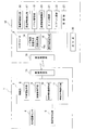
- FIG. 2 is a block diagram showing the configurations of the portable device 1 and the control unit 2.
- the portable device 1 includes a biological recognition sensor 4, a registration instruction device 5, a wireless communication unit 13, and a control unit 7.
- the biometric recognition sensor 4 detects biometric information peculiar to the user, such as a fingerprint, a finger vein pattern, and a heartbeat.
- the biometric recognition sensor 4 in this example is a fingerprint sensor. When a person presses the tip of a finger against a detection unit arranged on the case surface of the portable device 1, the fingerprint pattern is detected as biometric information.
- the wireless communication unit 13 performs wireless communication with the control unit 2 of the automobile 12 at a short distance in the RF band. In this case, when the control unit 2 determines that the portable device 1 existing in the wireless communication range is registered in advance, wireless communication is possible.
- the control unit 7 includes a computer including a CPU, a ROM, and a RAM.
- Each of the biometric authentication unit 8, the communication control unit 9, and the biometric information registration unit 10 is a control program in which the CPU is stored in the ROM. It is realized by processing.
- the control part 7 is provided with the registration biometric information storage part 11 by the flash memory which has memorize
- the biometric information registration unit 10 stores the biometric information (in this example, fingerprint information) detected by the biometric recognition sensor 4 in the registered biometric information storage unit 11 in response to the registration instruction signal from the registration instruction device 5.
- biometric information in this example, fingerprint information
- a plurality of biological information can be registered in the registered biological information storage unit 11.
- the registration instruction device 5 is configured by a switch device that outputs a registration instruction signal by a predetermined operation by a registrant.
- the registration instruction device 5 is usually provided separately from the portable device 1 from the viewpoint of security. Therefore, it is preferable that the mobile phone 1 is used by being connected at the time of registration setting.
- the portable device 1 described above has a configuration in which a so-called “portable device” conventionally used in an electronic key system is provided with a fingerprint authentication function, but the portable device 1 has a short distance such as a fingerprint authentication function or Bluetooth. It may be a portable information terminal such as a smartphone or a tablet computer having a wireless function.
- the biometric authentication unit 8 compares the detected biometric information with the registered biometric information stored in the registered biometric information storage unit 11 and determines whether or not they match each other. Determine. If they match, the authentication flag 8a provided in the RAM is set.
- the communication control means 9 exchanges signals for inter-device authentication between the portable device 1 and the control unit 2 of the automobile 12.
- the inter-device authentication at this time is performed by transmitting an ID set in advance in the portable device 1 in response to receiving a request signal that the control unit 2 periodically transmits.
- the control unit 2 is a main control unit of the automobile 12 composed of a CPU, and performs control processing of each electrical equipment including the traveling system 30 based on execution of predetermined software.
- FIG. 2 shows the user information management means 14 and the portable device authentication means 15 for performing the authentication operation with the portable device 1, which are directly related to the operation of the automobile user information management system 100 according to the present invention. These are also realized by executing this software.
- the control unit 2 is connected to a vehicle information detection unit 16 that detects vehicle information.
- vehicle information detection unit 16 is, for example, a wheel speed sensor, a throttle sensor, a brake pedal sensor, a parking brake sensor, a steering sensor, and a shift sensor that are appropriately arranged in each part of the traveling system 30 of the automobile. The detection result by the sensor is supplied to the control unit 2 as vehicle information.
- the wheel speed sensor is a sensor that detects the rotational speed of the wheel.
- the throttle sensor is a sensor that detects the opening of the engine throttle.
- the brake pedal sensor is a sensor that detects the depression amount of the brake pedal.
- the parking brake sensor is a sensor that detects an operating state of the parking brake.
- the steering sensor is a sensor that detects the steering amount of the steering wheel.
- the shift sensor is a sensor that detects a shift position selected by the shift lever.
- control unit 2 is connected to a peripheral information detection unit 17 that detects a proximity state with an object existing in front, rear, and side of the automobile 12 as peripheral information.
- a peripheral information detection unit 17 for example, a stereo camera, a laser sensor, or a sonar sensor is used.
- the peripheral information detection unit 17 supplies the detection result of the peripheral information to the control unit 2.
- control unit 2 includes a wireless communication unit 18 that performs short-range wireless communication with the portable device 1, a door and trunk door lock drive unit 19, a seat drive mechanism unit 20, an audio device 21, a navigation device 22, and an in-vehicle air conditioner. 23 etc. It is connected with vehicle equipment.
- the user information management means 14 detects user information in association with the biological information transmitted from the portable device 1.
- user information for example, the position of the seat, the address of the home or work, the frequently visited place, the store, the air conditioning environment in the car, the inter-vehicle distance with the preceding vehicle according to the speed of the car, the brake operation There is an inter-vehicle distance (brake operation timing) with the preceding vehicle.
- the seat drive mechanism unit 20 can adjust the seat position in the front-rear direction by sliding the position of the seat by converting the rotational force of the motor into a linear motion using a rack and pinion. Therefore, the user information management means 14 can detect the position of the seat as user information from the number of rotations of the pinion in the forward and reverse directions.
- the user information management means 14 can detect the user information of the address of the home or work by being input to the navigation device 22 by the user. And the user information management means 14 can detect the frequently visited places and shops by inputting the addresses of those places to the navigation device 22 and setting the guidance to the destination.
- the air conditioning environment in the vehicle can be detected by the user information management means 14 from the temperature, air volume, and wind direction information set by the user in the air conditioner 23 in the vehicle.
- the user information management means 14 can detect from the detection information which the vehicle information detection part 16 and the periphery information detection part 17 output when a user drives the driving system 30 by driving the automobile 12.
- a stereo camera 28 in which a pair of cameras 26 and 27 (see FIG. 3) that detect the field of view ahead of the traveling direction of the automobile 12 is arranged on the left and right of the front windshield is used for the peripheral information detection unit 17. be able to.
- the user information management means 14 performs pattern matching processing on the images sent from the cameras 26 and 27, and detects the presence of the vehicle or motorcycle by detecting the contour of the scenery captured by the images.
- An image processing unit 14a for determination is provided. Therefore, a pattern data file in which the image features to be detected are registered in advance is set in the ROM. And the user information management means 14 judges that it is a preceding vehicle, when the image of the left front side which the camera 26 imaged, and the image of the right front side which the camera 27 imaged have each caught the car, the motorcycle, etc. in common, A parallax image is generated and the distance to the detection target is measured.
- the vehicle information detecting unit 16 takes in the speed of the host vehicle detected by the wheel speed sensor at this time, and maintains the inter-vehicle distance. When the vehicle speed is detected.
- the user information management means 14 detects the inter-vehicle distance from the preceding vehicle when the user performs the brake operation from the inter-vehicle distance measured when the vehicle information detection unit 16 detects the brake operation by the brake pedal sensor. To do.
- the control unit 2 transmits the information detected by the user information management means 14 and the biological information acquired from the portable device 1 to the cloud server 3.
- the cloud server 3 includes a user information database 3a that stores biometric information and user information detected by the control unit 2 in association with each other, and stores various user information transmitted from the control unit 2 in the user information database 3a. I will do it.
- FIG. 4 is a flowchart showing the operation of the portable device 1, and the control unit 7 of the portable device 1 determines whether or not the biological information is detected by the biological recognition sensor 4 by the biometric authentication means 8 (step S1).
- the biometric sensor 4 detects biometric information based on the fingerprint.
- the biometric authentication unit 8 collates the detected biometric information with the registered biometric information stored in the registered biometric information storage unit 11 to register the user in advance. It is determined whether or not the user is a new user (step 2). However, when the collation does not match and the user is not a registered user, the process of step S4 is performed. The operation at this time will be clarified later.
- the control unit 7 establishes a wireless communication connection with the control unit 2 of the automobile 12. Is made possible (step S3).
- the state in which wireless communication connection is possible means that when the control unit 2 of the automobile 12 transmits a request signal by the portable device authentication means 15, the portable device 1 transmits an ID by the communication control means 9 in response thereto. It is a state that can be done. In this state, when the portable device 1 approaches the vehicle and receives a request signal from the control unit 2, an ID signal is transmitted.
- FIG. 5 is a flowchart showing the operation of “recognition of portable device” by the portable device authentication means 15 of the control unit 2.
- the portable device recognition means 15 transmits a request signal for requesting an ID to the portable device 1 (step S11).
- the biometric authentication unit 8 confirms that the user is a registered user and the wireless communication connection is possible
- the ID is transmitted when the request signal is received.
- the portable device authentication means 15 determines whether or not the ID matches a preset ID (step S12), and recognizes the presence of the portable device 1 if the ID matches (step S13). .
- authentication between the control unit 7 and the control unit 2 is established.
- step S 5 when authentication with the control unit 2 is established (“YES” in step S ⁇ b> 4), the portable device 1 uses the biological information detected by the biological recognition sensor 4 as the control unit 2. (Step S5). However, when the authentication with the control unit 2 is not established, the wireless communication connection with the control unit 2 is switched to an impossible state (step S5).
- control unit 2 outputs a door lock release signal to the door lock drive unit 19 to release the door lock when authentication with the portable device 1 is established (step S14), and a portable device recognition process routine is performed. Exit.
- control unit 2 executes predetermined software and controls each electrical device in the traveling system 30 of the vehicle 12 in response to a user operation, thereby causing the vehicle 12 to travel. .
- FIG. 6 is a flowchart showing the operation of “user information management” by the user information management means 15 of the control unit 2.
- the user information management means 15 accesses the cloud server 3 (step S21), and inquires whether user information corresponding to the biological information transmitted from the portable device 1 is stored (step S22).
- step S23 If user information is stored, it is downloaded and the air conditioning temperature in the vehicle, audio volume, seat position, etc. are set to conditions according to the user based on the acquired user information (step S23).
- the setting at this time includes supplying user information of the user's home and workplace, frequently visited places, and store addresses to the navigation device 22. Therefore, if the destination is one of these addresses, the user only needs to select a location when setting the destination in the navigation device 22.
- the inter-vehicle distance and the brake operation timing are mainly useful information for the autonomous driving vehicle, but will become clear later.
- step S24 when the user information linked
- the setting contents are collected as user information (step S24). Further, even when user information is stored in the cloud server 3 and the setting according to the user is performed in step S23, the user information is collected in step S24 because it may be changed after that. .
- the collection of the office or home address user's address in the user information from the portable terminal such as a smartphone carried by the user to the control unit 2 is performed.
- the user information management means 14 can also detect by transmitting. In this case, the user transmits the portable terminal to the control unit 2 by a wired connection such as USB or a short-distance wireless connection such as Bluetooth or Wi-Fi.
- the user information management unit 14 stores the collected user information in the cloud Whether to upload to the server 3 is determined (step S25).
- the user information is not initially stored in the cloud server 3
- the user information collected together with the biological information is transferred to the cloud server 3.
- the user information management means 14 ends the user information management routine.
- the inter-vehicle distance and the brake operation timing are information mainly applied in the case of an autonomous driving vehicle.
- Level 1 is called a safe driving support system, where the vehicle performs acceleration, steering, or braking.
- Level 2 is called a semi-automatic driving system (semi-automatic driving), in which a vehicle simultaneously performs a plurality of operations of acceleration, steering, and braking.
- Level 3 is a state in which acceleration, steering, and braking are all performed by the vehicle and the driver responds only in an emergency.
- Level 4 is called a fully automatic driving system in which acceleration, steering and braking are all performed by a person other than the driver and the driver is not involved at all.
- Levels 2 to 4 are also called automated driving systems ("Step SIP (Strategic Innovation Creation Program) Automated Driving System Research and Development Plan", November 13, 2014, Cabinet Office, Policy Director (Science Technology and innovation)). Therefore, “automatic driving” in this specification basically refers to automatic driving at a fully automated level from level 1 to level 4 described above.
- the user's preferred distance between vehicles and brake operation timing are acquired as user information, and during automatic driving, the vehicle automatically travels at the distance between vehicles and brake operation timing based on this data. This can give the user a sense of security.
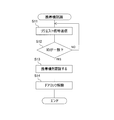
- FIG. 7 is a flowchart for explaining the operation in which the user information management means 14 measures the inter-vehicle distance in step S24.
- the image processing unit 14a takes in image data from the left and right cameras of the stereo camera (step S31). Then, the image processing unit 14a refers to the pattern data file, performs pattern matching processing on each image captured by the cameras 26 and 27, and recognizes the contour of the detection target, so that there is a preceding vehicle. It is determined whether or not (step S32).
- the image processing unit 14a generates a parallax image by fixing the position of the preceding vehicle in these two images and superimposing them.
- An inter-vehicle distance from the preceding vehicle is measured from the image by calculation (step S33).
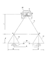
- FIG. 3 is a diagram schematically showing the relationship between the distances from both the cameras 26 and 27 to the preceding vehicle 25 in the parallax image.
- the triangle t1 having the three focal points f1 and f2 of the cameras 26 and 27 and the position O of the preceding vehicle 25, and the three vertexes of both ends of the parallax D of the camera 26 and the focal point f1.
- the user information management means 14 detects the speed of the host vehicle from the wheel speed sensor, but periodically acquires the inter-vehicle distance L and the speed. The distance between the vehicles maintained by the user is detected according to the speed. And the user information management means 14 calculates the average value of the distance between vehicles in each speed step for every 10 km / h, for example, and makes it the user information of the distance between vehicles.
- the user information management means 14 acquires the inter-vehicle distance L detected by the image processing unit 14a and the speed detected from the wheel speed sensor, and is also 10 km / The average value of the inter-vehicle distance at each speed stage for each h is calculated and used as the user information of the inter-vehicle distance (that is, the brake operation timing) for performing the brake operation.
- the user information management means 14 transmits the user information of the inter-vehicle distance and the brake operation timing to the cloud server 3 in step S26 together with other user information.
- these user information have been sent together. It is stored in the user information database in association with the biological information.
- the user information sent to the cloud server 3 is downloaded by access from the control unit 2 of the automobile.
- the control unit 2 is relieved to the user.
- the automatic driving is controlled by controlling the traveling system 30 so as to realize an inter-vehicle distance and a brake operation timing that give a feeling.
- the automobile user information management system 100 in order to acquire user information of a user in association with individual biometric information of the user and store it in the cloud server 3, and to download user information corresponding to the biometric information, Even if changes, the same in-vehicle environment and automatic driving conditions can be provided to the user. Or, in the case of the same car, even if the users are different, the in-vehicle environment and the conditions of automatic driving according to the users can be provided for each user.
- biometric authentication is performed by the portable device 1, but the biometric recognition sensor 4 and the biometric authentication means 8 may be provided in the automobile 12.
- the user information is acquired by the user information management means 14 provided in the control unit 2 of the automobile 12 and uploaded to the cloud server 3 together with the biological information.
- the user includes a fingerprint sensor.
- a system may be used in which biometric information and user information are set by accessing directly from an information terminal such as a personal computer.
- the cloud server 3 transmits a web page when a user accesses an established website from an information terminal. And a user inputs user information and biometric information into a web page. Regarding the inter-vehicle distance and the brake operation timing, the cloud server 3 may display a vehicle driving simulation on a web page so that the user can input the inter-vehicle distance and the brake operation timing from the information terminal.
- each music user uploads the music information reproduced from the audio device 21 to the cloud server 3 together with the biometric information of the user by using a music medium such as a CD or an MP3 player. It is stored in the information database 3a. Then, the control unit 2 extracts the common music from the music information of each person downloaded from the cloud server 3, so that the music that the user likes in common can be reproduced from the audio device 21.
- the user information includes personal information such as home and work addresses, and when automatic driving becomes popular in the future, it may be necessary to include highly confidential personal information such as chronic diseases. It is done. There is a risk in storing these personal information in the cloud server 3. Therefore, it is preferable to store personal information in the user information in the portable device 1 and store other information in the cloud server 3. In order to hold personal information in the portable device 1, it is directly input from an information terminal owned by the user.
- the portable device 1 acquires the biological information of the user by the biological recognition sensor 4, the portable device 1 transmits personal information together with the biological information to the control unit 2, and the control unit 2 associates the biological information with the cloud server 3. Download user information other than stored personal information.
- the cloud server 3 when the cloud server 3 stores user information including personal information, the cloud server 3 encrypts and stores the user information and decrypts the user information downloaded by the control unit 2. Obtain.
- the key information to be decrypted is set in advance by the user and input to the portable device 1.
- the portable device 1 obtains the user's biological information by the biological recognition sensor 4, the key information is displayed together with the biological information. Transmit to the control unit 2.
Abstract
搭乗する個々のユーザの性向に応じて、自動車の機能を制御することが可能な自動車ユーザ情報管理システムを提供する。クラウドサーバ(3)は、自動車の個々のユーザに依拠するそれぞれのユーザ情報を当該ユーザの生体情報に関連付けて格納している。自動車(12)のコントロールユニット(2)は、搭乗するユーザの生体情報を生体認証手段(8)が認証すると、認証された生体情報に基づきクラウドサーバ(3)からユーザ情報をダウンロードする。そして、コントロールユニット(2)は、ダウンロードした生体情報に応じて自動車の機能を制御する。
Description
本発明は、自動車におけるユーザによって調節可能な機能をユーザ個々の性向に応じて、自動的に設定することが可能な自動車ユーザ情報管理システムに関する。
近年、自動車では、ユーザの利便性やセキュリティーの向上を図るべく様々な取り組みが行われてきている。例えば、スマートキーを携帯したユーザが車体に近づくだけでドアロックの解錠やエンジンの始動許可等を行なったりしている。
そして、さらには、そのとき搭乗した自動車のユーザの好みや性向を表わすユーザ情報に応じて、運転手依存の機能の実行を選択的に可能にする車載コンピュータシステムが知られている(特許文献1を参照)。
しかしながら、上記従来技術では、1つ以上の運転手のプロフィールに関する現在の運転データ/挙動(ユーザ情報)に基づいて運転手の身元を推測し、推測された運転手の身元に基づいて運転手依存の機能の実行を選択的に可能にする車載コンピュータシステムである。そのため、車載コンピュータシステムは、複数のユーザごとに過去の運転データ/挙動を蓄積する必要があり、運転手の身元に基づいて運転手依存の機能の実行を選択的に可能な状態に至るまでには運転手のプロフィールを確立する必要があり、それには学習のための長い時間を要する。
本発明は、上記点に鑑みて、ユーザの身元を推測せずともユーザ個々を確実且つ容易に認識し得る自動車ユーザ情報管理システムを提供するものである。
本発明の自動車ユーザ情報管理システムは、個々の自動車ユーザに依拠するユーザ情報を当該ユーザの生体情報に関連付けて格納しているクラウドサーバと、検出された前記生体情報を認証する生体認証手段と、前記認証された前記生体情報に基づき前記クラウドサーバからダウンロードした前記ユーザ情報に応じて、自動車におけるユーザによって調節可能な機能を制御するコントロールユニットと、を備える。
そして、前記コントロールユニットは、ユーザが前記自動車内での調節により設定した内容を当該ユーザに依拠するユーザ情報として検出して、前記生体認識センサが認識している前記生体情報と共に前記クラウドサーバに送信するユーザ情報管理手段を有するようにするとよい。これにより、ユーザが自動車内で直接設定した内容がクラウドサーバに記憶されることになる。
ここで、前記ユーザ情報は、車内空調温度、オーディオの音量、座席位置の何れかを含むものである。そして、前記ユーザ情報は、運転の目的地に関する情報や、先行車両との車間距離及びブレーキ操作を行うときの車間距離であってもよい。車間距離は、ステレオカメラからの画像を処理して測定するのが好適である。
また、前記生体認証手段は、ユーザによって携帯される携帯機に設けて、前記携帯機は、前記生体認証手段が生体認証することで、前記コントロールユニットとの通信が可能となって認証した前記生体情報を送信し、前記コントロールユニットは受信した前記生体情報に関連付けられた前記ユーザ情報を前記クラウドサーバからダウンロードするシステム構成が可能である。
そして、この携帯機は、生体認証機能を備える専用の機器に限るものではなく、生体認証機能を有するものであればスマートフォンやタブレットコンピュータ等の汎用の携帯情報端末機であってもよい。
本発明の自動車ユーザ情報管理システムによれば、ユーザの特有の生体情報で認識するため、運転手のプロフィールを確立するまでの時間を必要とせず、ユーザ情報を蓄積しながら自動車の機能を搭乗者に好みに応じて調節することができる。
以下、本発明に係る自動車ユーザ情報管理システムの実施の形態を図面に基づき説明する。
図1は、自動車ユーザ情報管理システム100の構成全体を概念図で示している。自動車ユーザ情報管理システム100は、ユーザによって携帯される携帯機1と、自動車12に搭載されるコントロールユニット2と、クラウドサーバ3とからなる。コントロールユニット2と、クラウドサーバ3とは通信ネットワーク6を介して接続される。
図2は、携帯機1とコントロールユニット2のそれぞれの構成をブロック図で示している。携帯機1は、生体認識センサ4、登録指示装置5、無線通信部13、制御部7を備える。生体認識センサ4は、指紋、指の静脈パターン、心臓の鼓動等のユーザ特有の生体情報を検知する。本例での生体認識センサ4は指紋センサであり、携帯機1のケース表面に配置されている検知部に人が指の先端を押しつけることで、その指紋のパターンを生体情報として検出する。
そして、無線通信部13は、RF帯で自動車12のコントロールユニット2と近距離で無線通信する。この場合、コントロールユニット2が無線通信範囲内に存在する携帯機1が予め登録されたものであることを判別したとき、無線通信が可能となる。
また、制御部7は、CPU、ROM、RAMを含むコンピュータで構成されており、生体認証手段8、通信制御手段9及び生体情報登録手段10のそれぞれは、CPUがROMに格納されている制御プログラムを処理することで実現される。そして、制御部7は、登録生体情報を記憶しているフラッシュメモリによる登録生体情報記憶部11を備えている。
生体情報登録手段10は、登録指示装置5からの登録指示信号に応答して、生体認識センサ4が検知している生体情報(本例では指紋情報)を登録生体情報記憶部11に格納する。この場合、登録生体情報記憶部11には複数の生体情報を登録することができる。登録指示装置5は、登録者による所定の操作により、登録指示信号を出力するスイッチ装置によって構成されるが、セキュリティーの面から、登録指示装置5は、通常、携帯機1とは別体で設けて、登録設定時に携帯機1に接続して使用するように構成するのが好ましい。
以上に説明した携帯機1は、従来から電子キーシステムで使用されているいわゆる「携帯機」に指紋認証機能を備えた構成であるが、携帯機1は、指紋認証機能やブルートゥース等の近距離無線機能を有するスマートフォンやタブレットコンピュータ等の携帯型の情報端末機であってもよい。
生体認証手段8は、生体認識センサ4に指先が触れると、検知された生体情報と登録生体情報記憶部11に記憶されている登録生体情報とを比較して、互いに一致しているか否かを判別する。そして、一致しているときには、前記RAMに設けている認証フラグ8aをセットする。
通信制御手段9は、携帯機1と自動車12のコントロールユニット2との間で機器間認証のための信号の授受を行う。このときの機器間認証は、コントロールユニット2が定期的に送信するリクエスト信号の受信に応答して、携帯機1に予め設定されているIDを送信することで行われる。
コントロールユニット2は、CPUからなる自動車12の主制御部であり、走行系30を含めた各電装機器の制御処理を予め定められたソフトウェアの実行に基づいて実施する。図2では、本発明に係る自動車ユーザ情報管理システム100の動作と直接関係している、ユーザ情報管理手段14と、携帯機1との認証動作を行なう携帯機認証手段15が示されているが、これらもこのソフトウェアを実行することで実現される。
そして、コントロールユニット2には、車両の情報を検出する車両情報検出部16が接続されている。車両情報検出部16としては、例えば、自動車の走行系30を構成する各部に適宜配置されている車輪速センサ、スロットルセンサ、ブレーキペダルセンサ、パーキングブレーキセンサ、ステアリングセンサ、及びシフトセンサであり、これらセンサによる検出結果は車両情報としてコントロールユニット2へ供給される。
車輪速センサは、車輪の回転速度を検出するセンサである。スロットルセンサは、エンジンスロットルの開度を検出するセンサである。ブレーキペダルセンサは、ブレーキペダルの踏込量を検出するセンサである。パーキングブレーキセンサは、パーキングブレーキの作動状態を検出するセンサである。ステアリングセンサは、ステアリングホイールの操舵量を検出するセンサである。シフトセンサは、シフトレバーにより選択されるシフトポジションを検出するセンサである。
また、コントロールユニット2には、自動車12の前方、後方、及び側方に存在する物体との近接状態を周辺情報として検出する周辺情報検出部17が接続されている。周辺情報検出部17としては、例えば、ステレオカメラ、レーザセンサ、又はソナーセンサが用いられる。周辺情報検出部17は、周辺情報の検出結果をコントロールユニット2へ供給する。
さらに、コントロールユニット2は、携帯機1との近距離無線通信を行う無線通信部18、ドアやトランクのドアロック駆動部19、座席駆動機構部20、オーディオ機器21やナビゲーション装置22、車内空調機23等の車載機器と接続されている。
ユーザ情報管理手段14は、携帯機1から送信されてくる生体情報に関連付けて、ユーザ情報を検出する。この場合のユーザ情報としては、例えば座席の位置・自宅や職場の住所・頻繁に訪れる場所や店・車内の空調環境・自動車の速度に応じた先行車との車間距離・ブレーキ操作を行うときの先行車両との車間距離(ブレーキ操作時期)等がある。
座席駆動機構部20は、モータの回転力をラック・アンド・ピニオンで直線方向の動きに変換することで座席の位置をスライドさせて、座席位置を前後方向に調整可能にしている。したがって、ユーザ情報管理手段14は、ピニオンの正逆方向での回転数から座席の位置をユーザ情報として検出することができる。
自宅や職場の住所のユーザ情報は、ユーザによってナビゲーション装置22へ入力されることで、ユーザ情報管理手段14は検出することができる。そして、頻繁に訪れる場所や店についても、ナビゲーション装置22へのそれらの場所の住所の入力や目的地までの案内設定でユーザ情報管理手段14は検出することができる。
車内の空調環境は、ユーザが車内空調機23に設定する温度や風量・風向きの情報からユーザ情報管理手段14は検出することができる。
また、ユーザ情報管理手段14は、ユーザが自動車12を運転して走行系30を駆動したときの車両情報検出部16及び周辺情報検出部17が出力する検出情報から検出することができる。車間距離を検出するには、自動車12の進行方向前方の視界を検知する一対のカメラ26、27(図3参照)をフロントウインドシールドの左右に配置したステレオカメラ28を周辺情報検出部17に用いることができる。
したがって、ユーザ情報管理手段14は、カメラ26、27から送られてくる画像にパターンマッチング処理を行って、画像が捉える景色の中から自動車や自動二輪車等の輪郭を検出することにより、その存在を判別する画像処理部14aを備える。そのため、前記ROMには、これら検知対象の画像特徴が予め登録されているパターンデータファイルが設定されている。そして、ユーザ情報管理手段14は、カメラ26が撮像した左前方側の画像とカメラ27が撮像した右前方側の画像が自動車や自動二輪車等をそれぞれ共通に捉えていると先行車両と判断し、視差画像を生成して検知対象までの距離を測定する。
ユーザ情報管理手段14は、このようにして先行車両との車間距離を測定すると、このとき車両情報検出部16が車輪速センサによって検知している自車両の速度を取り込み、当該車間距離を維持しようとするときの車両速度を検出する。
また、ユーザ情報管理手段14は、車両情報検出部16がブレーキペダルセンサによりブレーキ操作を検出したときに測定している車間距離から、ユーザがブレーキ操作を行うときの先行車両との車間距離を検出する。
コントロールユニット2は、ユーザ情報管理手段14が検出したこれら情報と携帯機1から取得した生体情報とをクラウドサーバ3に送信する。
クラウドサーバ3は、生体情報と共にコントロールユニット2で検出されたユーザ情報とを関連付けて格納するユーザ情報データベース3aを備えて、コントロールユニット2から送信されてくる各種のユーザ情報をユーザ情報データベース3aに格納していく。
上記構成による自動車ユーザ情報管理システム100の動作を図4乃至図7のフローチャートに基づき説明する。
図4は携帯機1の動作を示すフローチャートで、携帯機1の制御部7は、生体認証手段8によって、生体認識センサ4で生体情報が検出されたかを判別している(ステップS1)。そして、ユーザが携帯機1のケース表面に指先を載せると、生体認識センサ4は指紋による生体情報が検出される。
生体認識センサ4で生体情報が検出されると、生体認証手段8は、検出された生体情報と登録生体情報記憶部11に記憶されている登録生体情報とを照合して、ユーザが予め登録されたユーザであるか否かを判定する(ステップ2)。しかし、照合が一致せず登録ユーザでないときにはステップS4の処理となるが、このときの動作については後に明らかとなる。
生体認証手段8は、生体情報の一致により生体情報が登録された登録ユーザであることを確証すると(ステップS2の「YES」)、制御部7は、自動車12のコントロールユニット2との無線通信接続を可能な状態とする(ステップS3)。ここで、無線通信接続が可能な状態とは、自動車12のコントロールユニット2が携帯機認証手段15によってリクエスト信号を発信したとき、これに応答して携帯機1が通信制御手段9によってIDを送信することができる状態である。この状態では、携帯機1が自動車に近づいてコントロールユニット2からのリクエスト信号を受信するとID信号を送信することになる。
図5は、コントロールユニット2の携帯機認証手段15による「携帯機認識」の動作を示すフローチャートである。携帯機認識手段15は、携帯機1へIDを要求するリクエスト信号を発信している(ステップS11)。そして、携帯機1側において、ユーザが登録ユーザであることを生体認証手段8が確証して、無線通信接続が可能な状態となっているとき、このリクエスト信号を受信するとIDを送信する。これにより、携帯機認証手段15は、このIDが予め設定されているIDと一致しているかを判別し(ステップS12)、一致していると当該携帯機1の存在を認識する(ステップS13)。これによって、制御部7とコントロールユニット2との間の認証が成立したことになる。
そして、図4のフローチャートの説明に戻って、携帯機1は、コントロールユニット2との認証が成立したとき(ステップS4の「YES」)、生体認識センサ4で検出された生体情報をコントロールユニット2に送信する(ステップS5)。しかし、コントロールユニット2との認証が不成立のときは、コントロールユニット2との無線通信接続を不能な状態に切り替える(ステップS5)。
一方、コントロールユニット2では、携帯機1との間での認証の成立により、ドアロック駆動部19にドアロック解除信号を出力してドアロックを解除し(ステップS14)、携帯機認識処理のルーチンを終了する。
そして、特に説明しないが、コントロールユニット2は、予め定められたソフトウェアを実行し、ユーザの操作に応答して、自動車12の走行系30における各電装機器を制御することで、自動車12を走行させる。
図6は、コントロールユニット2のユーザ情報管理手段15による「ユーザ情報管理」の動作を示すフローチャートである。ユーザ情報管理手段15は、クラウドサーバ3にアクセスして(ステップS21)、携帯機1から送信されてきた生体情報に対応しているユーザ情報が格納されているかを問い合わせる(ステップS22)。
ユーザ情報が格納されている場合には、これをダウンロードして、取得したユーザ情報に基づき車内空調温度やオーディオの音量、座席位置等をユーザに応じた条件に設定する(ステップS23)。このときの設定には、ユーザの自宅や職場、頻繁に訪れる場所や店の住所のユーザ情報をナビゲーション装置22へ供給することも含まれている。よって、ユーザは目的地がこれら住所の何れかであれば、ナビゲーション装置22に目的地を設定する場合に、場所を選択するだけの操作ですむ。尚、ユーザ情報で、車間距離とブレーキ操作時期については、主に自動運転車に有用な情報となるが後に明白となる。
そして、クラウドサーバ3にこの生体情報に関連付けされたユーザ情報が格納されていない場合には(ステップS22の「NO」)、ユーザによって座席駆動部20、オーディオ機器21、ナビゲーション装置22、空調機23が操作されたとき、それらの設定内容をユーザ情報として収集されることになる(ステップS24)。また、クラウドサーバ3にユーザ情報が格納されていて、ステップS23でユーザに応じた設定を行った場合も、その後に変更されることもあるために、ステップS24でのユーザ情報の収集が行われる。
ユーザ情報での職場や自宅の住所、よく行く場所や店の住所の収集は、ユーザによるナビゲーション装置22への入力操作以外に、ユーザが携帯しているスマートフォン等の携帯端末機からコントロールユニット2に送信することでユーザ情報管理手段14は検出することもできる。この場合、ユーザが携帯端末機をコントロールユニット2にUSB等による有線接続又はブルートゥースやWi-Fi等の近距離無線接続により伝達する。
そして、ユーザによる自動車12の運転が終了したとき、例えば、シフトレバーにより選択されるシフトポジションがパーキングとなったことをシフトセンサが検知したとき、ユーザ情報管理手段14は、収集したユーザ情報をクラウドサーバ3にアップロードの要否を判定する(ステップS25)。そして、当初にユーザ情報がクラウドサーバ3に格納されていなかったときには、生体情報と共に収集したユーザ情報をクラウドサーバ3に転送する。また、格納されていても変更があった場合には、ユーザ情報の変更された項目の情報を生体情報と共にクラウドサーバ3に転送する。そして、ユーザ情報管理手段14は、ユーザ情報管理のルーチンを終了する。
ユーザ情報で車間距離やブレーキ操作時期については、主に自動運転車の場合に適用される情報である。
この明細書で述べる「自動運転」について説明すると、近年、道路交通の安全をより一層向上させるための自動運転システムの研究開発も進められている。このシステムは、自動車が周囲の環境を認識して自動走行するものであるが、我が国では、自動車等の車輌の自動走行システムについて、その自動化レベルがレベル1からレベル4まで4段階に分けて定義されている。レベル1は、加速・操舵・制動のいずれかを自動車が行い、安全運転支援システムと呼ばれる。レベル2は、加速・操舵・制動の内の複数の操作を同時に自動車が行い、準自動走行システム(半自動運転)と呼ばれる。レベル3は、加速・操舵・制動を全て自動車が行い、緊急時のみドライバーが対応する状態で、これも準自動走行システムと呼ばれる。レベル4は、加速・操舵・制動を全てドライバー以外が行い、ドライバーが全く関与しない状態で完全自動走行システムと呼ばれる。また、レベル2からレベル4までを自動走行システムとも呼んでいる(「ステップSIP(戦略的イノベーション創造プログラム)自動走行システム研究開発計画」、2014年11月13日、内閣府、政策統括官(科学技術・イノベーション担当))。そこで、本明細書における「自動運転」とは、基本的に上記レベル1からレベル4までの全自動化レベルの自動走行を言うものとする。
しかしながら、自動車の運転には人によって異なる性向がある。例えば、速度に応じた先行車との車間距離やブレーキを掛けるタイミングについては、人によって微妙に異なため、運転操作に関与せずに同乗しているとき、自身が意識する車間距離より短い又はブレーキの操作時期が遅いと、運転に不安を感じることになる。また、逆の場合にはまだるく感じたりすることがある。
そのため、ユーザがマニュアル運転を行っているとき、ユーザが好む車間距離やブレーキ操作時期をユーザ情報として取得しておき、自動運転時には、自動車がこのデータに基づいて車間距離やブレーキ操作時期で自動走行すれば、ユーザに安心感を与えることができる。
図7は、ユーザ情報管理手段14が上記ステップS24で車間距離を測定する動作を説明するフローチャートである。この動作では、先ず画像処理部14aが、ステレオカメラの左右のカメラからの画像データを取り込む(ステップS31)。そして、画像処理部14aは、パターンデータファイルを参照して、カメラ26、27が捉えたそれぞれの画像にパターンマッチング処理を行って検知対象の輪郭を認識することで、先行車両が存在しているか否かを判別する(ステップS32)。
このとき、一対のカメラがそれぞれ前方の同じ先行車を捉えていると、画像処理部14aは、この2通りの画像で先行車の位置を固定にして重ね合せることで視差画像を生成し、この画像から先行車との車間距離を演算により測定する(ステップS33)。
図3は視差画像における両方のカメラ26、27から先行車両25までの距離の関係を模式的に示す図である。図3において、両方のカメラ26、27の焦点位置f1、f2と先行車両25の位置Oとを3つの頂点とする三角形t1と、カメラ26の視差Dの両端と焦点位置f1とを3つの頂点とする三角形t2とは相似形であり、三角形t1の高さ寸法をL(すなわち、先行車両25までの距離)、三角形t2の高さ寸法をF(すなわち、カメラの焦点距離)、カメラ26、27との間の距離をAとすれば、(L/F)=(A/D)の関係式が成り立つ。このとき、視差Dは、画像データの画素数から求めることができ、この原理を基にして、先行車両25までの車間距離Lを演算することができる。
ユーザ情報管理手段14は、このようにして画像処理部14aが車間距離Lを測定したとき、自車両の速度を車輪速センサから検出するが、車間距離Lと速度を定期的に取得することで、速度に応じてユーザが保つ車間距離を検出する。そして、ユーザ情報管理手段14は、例えば、10km/h毎の各速度段階での車間距離の平均値を算出して、車間距離のユーザ情報とする。
また、ユーザ情報管理手段14は、ブレーキペダルセンサがブレーキ操作を検知する毎に、そのとき画像処理部14aが検出している車間距離Lと車輪速センサから検出する速度を取得し、同じく10km/h毎の各速度段階での車間距離の平均値を算出してブレーキ操作を行う車間距離(すなわち、ブレーキ操作時期)のユーザ情報とする。
そして、ユーザ情報管理手段14は、車間距離とブレーキ操作時期のユーザ情報も他のユーザ情報と共にステップS26でクラウドサーバ3に送信するが、クラウドサーバ3では、これらのユーザ情報を共に送られてきた生体情報に関連付けてユーザ情報データベースに格納する。
上記したように、クラウドサーバ3に送られたユーザ情報は、自動車のコントロールユニット2からのアクセスによりダウンロードされるが、自動車12が自動運転モードであるときは、コントロールユニット2は、当該ユーザに安心感を与える車間距離やブレーキ操作時期を実現するよう走行系30を制御しての自動運転を制御する。
上記自動車ユーザ情報管理システム100によれば、ユーザ個々の生体情報に対応付けてユーザのユーザ情報を取得してクラウドサーバ3に格納し、また生体情報に応じたユーザ情報をダウンロードするために、自動車が変わっても同じ車内環境や自動運転の条件をユーザに提供することができる。又は同じ自動車の場合には、ユーザが異なってもそのユーザに応じた車内環境や自動運転の条件をユーザ毎に提供することができる。
そして、自動車ユーザ情報管理システム100では携帯機1で生体認証を行うが、生体認識センサ4及び生体認証手段8を自動車12内に設けてもよい。
また、上記の実施形態においては、自動車12のコントロールユニット2に設けたユーザ情報管理手段14によって、ユーザ情報を取得して生体情報と共にクラウドサーバ3にアップロードしているが、ユーザが指紋センサを備えたパーソナルコンピュータ等の情報端末機から直接にアクセスして生体情報とユーザ情報とを設定するシステムであってもよい。
この実施形態では、クラウドサーバ3は、開設しているウェブサイトをユーザによって情報端末機からアクセスされると、ウェブページを送信する。そして、ユーザは、ウェブページにユーザ情報や生体情報を入力する。車間距離やブレーキ操作時期については、クラウドサーバ3はウェブページに自動車運転シミュレーションを表示することで、ユーザが情報端末機から車間距離やブレーキ操作時期を入力できるようにするとよい。
さらに、ユーザ情報として、好みの楽曲情報を設定することで、複数人で一台の自動車に同乗したとき、共通して好む楽曲をオーディオ機器から再生することもできる。このとき、各ユーザがCD等の音楽メディア又はMP3プレイヤーを用いて、オーディオ機器21から再生した楽曲情報を当該ユーザの生体情報と共にクラウドサーバ3にアップロードすることで、この楽曲情報はユーザ情報としてユーザ情報データベース3aに格納されている。そして、コントロールユニット2がクラウドサーバ3からダウンロードした各人の楽曲情報から共通する楽曲を抽出することで、共通して好む楽曲がオーディオ機器21から再生することができる。
また、ユーザ情報には、自宅や職場の住所等の個人情報が含まれており、将来的に自動運転が普及したとき、持病などの秘匿性の高い個人情報も含むことが必要なことが考えられる。そして、これら個人情報をクラウドサーバ3に格納しておくにはリスクがある。そこで、ユーザ情報の中の個人情報は携帯機1に保持しておき、その他の情報をクラウドサーバ3に格納するのが好ましい。個人情報を携帯機1で保持させるには、ユーザが所持している情報端末機から直接入力する。そして、携帯機1は、生体認識センサ4によりユーザの生体情報を取得したとき、この生体情報と共に個人情報をコントロールユニット2に送信し、コントロールユニット2は、この生体情報に関連付けてクラウドサーバ3が格納している個人情報以外のユーザ情報をダウンロードする。
一方、クラウドサーバ3で個人情報も含めたユーザ情報を格納しておく場合には、クラウドサーバ3は、ユーザ情報を暗号化して格納しておき、コントロールユニット2でダウンロードしたユーザ情報を復号して入手する。この場合、復号するキー情報は、ユーザが予め設定して携帯機1に入力しておき、携帯機1は、生体認識センサ4によりユーザの生体情報を取得したとき、この生体情報と共にキー情報をコントロールユニット2に送信する。
以上、本発明の好適な実施形態について詳細に説明したが、本発明は上記実施形態に限定されるものでなく、その技術的範囲内において、様々な変形又は変更を加えて実施することができる。
100 自動車ユーザ情報管理システム
1 携帯機
2 コントロールユニット
3 クラウドサーバ
8 生体認証手段
14 ユーザ情報管理手段
1 携帯機
2 コントロールユニット
3 クラウドサーバ
8 生体認証手段
14 ユーザ情報管理手段
Claims (8)
- 個々の自動車ユーザに依拠するユーザ情報を当該ユーザの生体情報に関連付けて格納しているクラウドサーバと、
検出された前記生体情報を認証する生体認証手段と、
前記認証された前記生体情報に基づき前記クラウドサーバからダウンロードした前記ユーザ情報に応じて、自動車におけるユーザによって調節可能な機能を制御するコントロールユニットと、
を備えた自動車ユーザ情報管理システム。 - 前記コントロールユニットは、ユーザが前記自動車内での調節により設定した内容を当該ユーザに依拠するユーザ情報として検出して、前記生体認識センサが認識している前記生体情報と共に前記クラウドサーバに送信するユーザ情報管理手段を有することを特徴とする請求項1に記載の自動車ユーザ情報管理システム。
- 前記ユーザ情報は、車内空調温度、オーディオの音量、座席位置の何れかを含むことを特徴とする請求項2に記載の自動車ユーザ情報管理システム。
- 前記ユーザ情報は、目的地に関する情報であることを特徴とする請求項2に記載の自動車ユーザ情報管理システム。
- 前記ユーザ情報は、先行車両との車間距離及びブレーキ操作を行うときの車間距離であることを特徴とする請求項2に記載の自動車ユーザ情報管理システム。
- 前記車間距離は、ステレオカメラからの画像を処理して測定することを特徴とする請求項5に記載の自動車ユーザ情報管理システム。
- 前記生体認証手段は、ユーザによって携帯される携帯機に設けられ、
前記携帯機は、前記生体認証手段が生体認証することで、前記コントロールユニットとの通信が可能となって認証した前記生体情報を送信し、
前記コントロールユニットは受信した前記生体情報に関連付けられた前記ユーザ情報を前記クラウドサーバからダウンロードすることを特徴とする請求項1又は2に記載の自動車ユーザ情報管理システム。 - 前記携帯機は、生体認証機能を備えた携帯情報端末機であることを特徴とする請求項6に記載の自動車ユーザ情報管理システム。
Applications Claiming Priority (2)
| Application Number | Priority Date | Filing Date | Title |
|---|---|---|---|
| JP2015168532A JP2017043268A (ja) | 2015-08-28 | 2015-08-28 | 自動車ユーザ情報管理システム |
| JP2015-168532 | 2015-08-28 |
Publications (1)
| Publication Number | Publication Date |
|---|---|
| WO2017038486A1 true WO2017038486A1 (ja) | 2017-03-09 |
Family
ID=58187513
Family Applications (1)
| Application Number | Title | Priority Date | Filing Date |
|---|---|---|---|
| PCT/JP2016/074126 WO2017038486A1 (ja) | 2015-08-28 | 2016-08-18 | 自動車ユーザ情報管理システム |
Country Status (2)
| Country | Link |
|---|---|
| JP (1) | JP2017043268A (ja) |
| WO (1) | WO2017038486A1 (ja) |
Cited By (5)
| Publication number | Priority date | Publication date | Assignee | Title |
|---|---|---|---|---|
| CN107316363A (zh) * | 2017-07-05 | 2017-11-03 | 奇瑞汽车股份有限公司 | 一种基于生物识别技术的汽车智能互联系统 |
| CN112298192A (zh) * | 2019-07-31 | 2021-02-02 | 比亚迪股份有限公司 | 车辆及其控制策略生成方法和装置 |
| WO2021124894A1 (ja) * | 2019-12-20 | 2021-06-24 | テイ・エス テック株式会社 | シートシステム |
| CN113395673A (zh) * | 2020-03-13 | 2021-09-14 | 丰田自动车株式会社 | 系统、车载装置以及信息处理方法 |
| WO2023189543A1 (ja) * | 2022-03-30 | 2023-10-05 | 株式会社デンソー | 車両用パーソナライズ設定システム、及び車両用パーソナライズ設定方法 |
Families Citing this family (9)
| Publication number | Priority date | Publication date | Assignee | Title |
|---|---|---|---|---|
| CN107578559A (zh) * | 2017-09-19 | 2018-01-12 | 奇瑞汽车股份有限公司 | 共享汽车的控制方法、装置及计算机可读存储介质 |
| KR101995124B1 (ko) * | 2017-09-20 | 2019-07-01 | 동국대학교 경주캠퍼스 산학협력단 | 생체 정보에 기반한 자동차 제어 시스템 |
| JP7087747B2 (ja) * | 2018-07-11 | 2022-06-21 | オムロン株式会社 | 車載機、運行管理装置、運行管理システム、及び運転者確認方法 |
| CN110789635B (zh) * | 2018-08-03 | 2022-08-12 | 黄学正 | 智能型移动载具 |
| JP7140067B2 (ja) | 2019-07-12 | 2022-09-21 | 株式会社デンソー | 車両制御装置、車両制御方法、及びプログラム |
| JP2023022544A (ja) | 2021-08-03 | 2023-02-15 | 株式会社Subaru | 乗員に応じた車両の設定システム、および車両 |
| JP2023022543A (ja) | 2021-08-03 | 2023-02-15 | 株式会社Subaru | 乗員に応じた車両の設定システム、および車両 |
| JP2023022547A (ja) | 2021-08-03 | 2023-02-15 | 株式会社Subaru | 乗員に応じた車両の設定システム、および車両 |
| JP2023022542A (ja) | 2021-08-03 | 2023-02-15 | 株式会社Subaru | 乗員に応じた車両の設定システム、および車両 |
Citations (6)
| Publication number | Priority date | Publication date | Assignee | Title |
|---|---|---|---|---|
| JP2007245842A (ja) * | 2006-03-15 | 2007-09-27 | Yokogawa Electric Corp | 走行制御システム |
| JP2007269268A (ja) * | 2006-03-31 | 2007-10-18 | Denso Corp | 自動車用ユーザーもてなしシステム |
| JP2009286343A (ja) * | 2008-05-30 | 2009-12-10 | Fujitsu Ten Ltd | 遠隔車両制御システム、乗員認証装置および遠隔車両制御方法 |
| JP2010105498A (ja) * | 2008-10-29 | 2010-05-13 | Toyota Motor Corp | 車群走行システム及び車群走行装置 |
| JP2015505284A (ja) * | 2011-12-29 | 2015-02-19 | インテル コーポレイション | 車両の乗員を識別するシステム、方法、及び装置 |
| JP2015128988A (ja) * | 2014-01-06 | 2015-07-16 | ハーマン インターナショナル インダストリーズ インコーポレイテッド | 自動の運転手識別 |
Family Cites Families (3)
| Publication number | Priority date | Publication date | Assignee | Title |
|---|---|---|---|---|
| JP3438279B2 (ja) * | 1993-05-19 | 2003-08-18 | マツダ株式会社 | 自動車の車速制御装置 |
| JP4743251B2 (ja) * | 2008-10-06 | 2011-08-10 | トヨタ自動車株式会社 | 追従制御装置 |
| JP5854133B2 (ja) * | 2012-06-05 | 2016-02-09 | トヨタ自動車株式会社 | 運転特性推定装置及び運転支援システム |
-
2015
- 2015-08-28 JP JP2015168532A patent/JP2017043268A/ja active Pending
-
2016
- 2016-08-18 WO PCT/JP2016/074126 patent/WO2017038486A1/ja active Application Filing
Patent Citations (6)
| Publication number | Priority date | Publication date | Assignee | Title |
|---|---|---|---|---|
| JP2007245842A (ja) * | 2006-03-15 | 2007-09-27 | Yokogawa Electric Corp | 走行制御システム |
| JP2007269268A (ja) * | 2006-03-31 | 2007-10-18 | Denso Corp | 自動車用ユーザーもてなしシステム |
| JP2009286343A (ja) * | 2008-05-30 | 2009-12-10 | Fujitsu Ten Ltd | 遠隔車両制御システム、乗員認証装置および遠隔車両制御方法 |
| JP2010105498A (ja) * | 2008-10-29 | 2010-05-13 | Toyota Motor Corp | 車群走行システム及び車群走行装置 |
| JP2015505284A (ja) * | 2011-12-29 | 2015-02-19 | インテル コーポレイション | 車両の乗員を識別するシステム、方法、及び装置 |
| JP2015128988A (ja) * | 2014-01-06 | 2015-07-16 | ハーマン インターナショナル インダストリーズ インコーポレイテッド | 自動の運転手識別 |
Cited By (10)
| Publication number | Priority date | Publication date | Assignee | Title |
|---|---|---|---|---|
| CN107316363A (zh) * | 2017-07-05 | 2017-11-03 | 奇瑞汽车股份有限公司 | 一种基于生物识别技术的汽车智能互联系统 |
| CN112298192A (zh) * | 2019-07-31 | 2021-02-02 | 比亚迪股份有限公司 | 车辆及其控制策略生成方法和装置 |
| CN112298192B (zh) * | 2019-07-31 | 2022-10-18 | 比亚迪股份有限公司 | 车辆及其控制策略生成方法和装置 |
| WO2021124894A1 (ja) * | 2019-12-20 | 2021-06-24 | テイ・エス テック株式会社 | シートシステム |
| CN114746304A (zh) * | 2019-12-20 | 2022-07-12 | 提爱思科技股份有限公司 | 座椅系统 |
| US20220371474A1 (en) * | 2019-12-20 | 2022-11-24 | Ts Tech Co., Ltd. | Seat system |
| US11845362B2 (en) | 2019-12-20 | 2023-12-19 | Ts Tech Co., Ltd. | Seat system with output by touch operation of sensors |
| CN113395673A (zh) * | 2020-03-13 | 2021-09-14 | 丰田自动车株式会社 | 系统、车载装置以及信息处理方法 |
| CN113395673B (zh) * | 2020-03-13 | 2024-04-09 | 丰田自动车株式会社 | 系统、车载装置以及信息处理方法 |
| WO2023189543A1 (ja) * | 2022-03-30 | 2023-10-05 | 株式会社デンソー | 車両用パーソナライズ設定システム、及び車両用パーソナライズ設定方法 |
Also Published As
| Publication number | Publication date |
|---|---|
| JP2017043268A (ja) | 2017-03-02 |
Similar Documents
| Publication | Publication Date | Title |
|---|---|---|
| WO2017038486A1 (ja) | 自動車ユーザ情報管理システム | |
| JP6751436B2 (ja) | 自律走行車両へのアクセス及び運転制御 | |
| JP7345919B2 (ja) | 車両 | |
| US10914596B2 (en) | Map information update system and map information update server | |
| US10384647B2 (en) | Electronic key system | |
| US20180154903A1 (en) | Attention monitoring method and system for autonomous vehicles | |
| JP6948559B2 (ja) | 運転者監視装置、及び運転者監視方法 | |
| JP6509361B2 (ja) | 駐車支援装置及び駐車支援方法 | |
| CN107380103B (zh) | 基于用户识别和云共享的汽车饰件自动调节方法及系统 | |
| JP2019204440A (ja) | 自動運転システム及び自動運転システムの制御方法 | |
| KR101484212B1 (ko) | 자동차의 운전자 인식 시스템 및 인식 방법 | |
| JP2017226309A (ja) | 車両制御装置 | |
| WO2019062953A1 (zh) | 车辆转向助力的控制方法和装置、存储介质和车辆 | |
| US9297665B2 (en) | System and method for sending a destination point to a vehicle navigation system from a portable electronic device | |
| JP6584904B2 (ja) | 操作者判定装置 | |
| CN108216087B (zh) | 利用对把手式门抓握方式的辨识识别用户的方法和装置 | |
| JP6925130B2 (ja) | 車両制御装置及び車両制御方法 | |
| JP6587467B2 (ja) | 操作者判定装置 | |
| JP6576781B2 (ja) | 車両設定装置 | |
| JP2021046154A (ja) | 車両制御計画生成装置及び車両の制御装置 | |
| JP2017052409A (ja) | 車両設定装置 | |
| WO2017017938A1 (ja) | ジェスチャ操作システム、方法およびプログラム | |
| JP6534586B2 (ja) | 判定装置 | |
| JP6599198B2 (ja) | 操作者判定装置 | |
| US11524642B2 (en) | System and method for setting information about vehicle |
Legal Events
| Date | Code | Title | Description |
|---|---|---|---|
| 121 | Ep: the epo has been informed by wipo that ep was designated in this application |
Ref document number: 16841518 Country of ref document: EP Kind code of ref document: A1 |
|
| NENP | Non-entry into the national phase |
Ref country code: DE |
|
| 32PN | Ep: public notification in the ep bulletin as address of the adressee cannot be established |
Free format text: NOTING OF LOSS OF RIGHTS PURSUANT TO RULE 112(1) EPC (EPO FORM 1205A DATED 30/05/2018) |
|
| 122 | Ep: pct application non-entry in european phase |
Ref document number: 16841518 Country of ref document: EP Kind code of ref document: A1 |