WO2017038485A1 - Système de clé électronique - Google Patents
Système de clé électronique Download PDFInfo
- Publication number
- WO2017038485A1 WO2017038485A1 PCT/JP2016/074125 JP2016074125W WO2017038485A1 WO 2017038485 A1 WO2017038485 A1 WO 2017038485A1 JP 2016074125 W JP2016074125 W JP 2016074125W WO 2017038485 A1 WO2017038485 A1 WO 2017038485A1
- Authority
- WO
- WIPO (PCT)
- Prior art keywords
- portable device
- user
- control unit
- biometric
- authentication
- Prior art date
Links
Images


Classifications
-
- B—PERFORMING OPERATIONS; TRANSPORTING
- B60—VEHICLES IN GENERAL
- B60R—VEHICLES, VEHICLE FITTINGS, OR VEHICLE PARTS, NOT OTHERWISE PROVIDED FOR
- B60R25/00—Fittings or systems for preventing or indicating unauthorised use or theft of vehicles
- B60R25/20—Means to switch the anti-theft system on or off
- B60R25/25—Means to switch the anti-theft system on or off using biometry
- B60R25/252—Fingerprint recognition
-
- A—HUMAN NECESSITIES
- A61—MEDICAL OR VETERINARY SCIENCE; HYGIENE
- A61B—DIAGNOSIS; SURGERY; IDENTIFICATION
- A61B5/00—Measuring for diagnostic purposes; Identification of persons
- A61B5/117—Identification of persons
- A61B5/1171—Identification of persons based on the shapes or appearances of their bodies or parts thereof
- A61B5/1172—Identification of persons based on the shapes or appearances of their bodies or parts thereof using fingerprinting
-
- B—PERFORMING OPERATIONS; TRANSPORTING
- B60—VEHICLES IN GENERAL
- B60R—VEHICLES, VEHICLE FITTINGS, OR VEHICLE PARTS, NOT OTHERWISE PROVIDED FOR
- B60R25/00—Fittings or systems for preventing or indicating unauthorised use or theft of vehicles
- B60R25/20—Means to switch the anti-theft system on or off
- B60R25/24—Means to switch the anti-theft system on or off using electronic identifiers containing a code not memorised by the user
-
- B—PERFORMING OPERATIONS; TRANSPORTING
- B60—VEHICLES IN GENERAL
- B60R—VEHICLES, VEHICLE FITTINGS, OR VEHICLE PARTS, NOT OTHERWISE PROVIDED FOR
- B60R25/00—Fittings or systems for preventing or indicating unauthorised use or theft of vehicles
- B60R25/20—Means to switch the anti-theft system on or off
- B60R25/25—Means to switch the anti-theft system on or off using biometry
-
- E—FIXED CONSTRUCTIONS
- E05—LOCKS; KEYS; WINDOW OR DOOR FITTINGS; SAFES
- E05B—LOCKS; ACCESSORIES THEREFOR; HANDCUFFS
- E05B49/00—Electric permutation locks; Circuits therefor ; Mechanical aspects of electronic locks; Mechanical keys therefor
-
- G—PHYSICS
- G06—COMPUTING; CALCULATING OR COUNTING
- G06F—ELECTRIC DIGITAL DATA PROCESSING
- G06F21/00—Security arrangements for protecting computers, components thereof, programs or data against unauthorised activity
- G06F21/30—Authentication, i.e. establishing the identity or authorisation of security principals
- G06F21/31—User authentication
- G06F21/32—User authentication using biometric data, e.g. fingerprints, iris scans or voiceprints
Definitions
- the present invention relates to an electronic key system, and more particularly to an electronic key system that allows an authorized user to give an operation instruction to a vehicle.
- detachable data storage means for storing biometric information of a registrant as registration data is set in the vehicle body, and a biometric sample collected from a passenger in a car
- a key system based on biometric authentication that enables opening / closing and operation of a door lock when the information matches registered data is disclosed (see, for example, Patent Document 1).
- the present invention provides an electronic key system that makes it possible to give instructions to a vehicle from a portable device that has been authenticated by a user.
- the electronic key system of the present invention is an electronic key system that instructs a control unit mounted on an automobile to operate by a portable device that is carried when the user wears it on the body, and stores biometric information of the user registered in advance.
- the portable device includes an attachment / detachment detection unit, and the biometric authentication unit determines whether the biometric information matches when the attachment / detachment detection unit detects wearing, and the portable device indicates that they match. And authentication between the control unit and the control unit.
- the biometric authentication unit may cancel the authentication when the attachment / detachment detection unit detects that the user has detached the portable device after the authentication is established. Thereby, only the wearer of a portable machine can give directions to a car.
- the portable device detects movement of a part where the user wears the portable machine, and when the movement detection means detects a specific movement of the part, the portable device moves to the automobile corresponding to the movement. It is good to provide the operation instruction
- control unit includes a portable device recognition unit that recognizes the portable device in which the wearer is confirmed to be a registered user by the biometric authentication unit, an imaging device that images the movement of the user, and the imaging An image recognition unit that detects a specific movement of the user based on imaging information from a unit, and an operation control unit that controls the operation of the automobile according to the detected specific movement.
- an instruction can be given to the automobile by performing image recognition processing of the movement of the registered user having authority.
- biometric information storage means and the biometric authentication means may each be provided in a cloud server.
- the control unit establishes authentication with the portable device based on the determination result of the biometric authentication unit by transferring the biological information transmitted from the portable device to the cloud server. be able to.
- the portable device can transmit the biometric information to the cloud server, and can establish authentication with the control unit based on the determination result of the biometric authentication means.
- a cloud server it is possible to establish authentication with the control units of a plurality of automobiles with a single portable device.
- the control unit can authenticate with the portable device.
- the propensity information can be downloaded. Thereby, the control unit can control operation
- the electronic key system of the present invention by obtaining the user's biometric information on the portable device side, there is no need to provide a plurality of biometric recognition sensors in the car according to the instructed item, which is simplified.
- An electronic key system based on biometric authentication is provided.
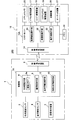
- FIG. 1 shows a block diagram of an overall configuration of an electronic key system according to a first embodiment of the present invention.
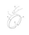
- One structural example of a bracelet-type portable device is shown in an external view.
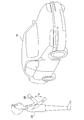
- indication to a motor vehicle by the motion of the arm which wore the portable machine is shown.
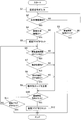
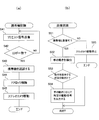
- 2 is a flowchart of the operation of the portable device in the electronic key system of FIG.
- the block diagram of the whole structure of the electronic key system by the 2nd Embodiment of this invention is shown.
- indication to a motor vehicle is shown.
- FIG. 7 is a flowchart of the operation of the portable device in the electronic key system of FIG. 7 shows a flowchart of the operation of the control unit of the automobile in the electronic key system of FIG.
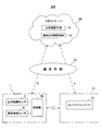
- An electronic key system by a 3rd embodiment of the present invention is a conceptual explanatory view.
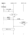
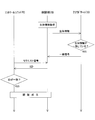
- FIG. 11 shows a sequence diagram until authentication between the portable device and the automobile in the electronic key system of FIG. 10 is established.
- FIG. 1 conceptually shows the entire configuration of the electronic key system 100 in a block diagram.
- the electronic key system 100 is a system for instructing an operation to the automobile 16 by wireless, and includes a portable device 1 carried by a user and a control unit 15 mounted on the automobile 16.
- the portable device 1 is attached to the bracelet 20 so that the user can wear it on the arm as shown in FIGS.
- the portable device 1 includes a biological recognition sensor 2, a motion detection sensor 3, an attachment / detachment detection sensor 4 that detects attachment / detachment of the bracelet 20 to a user, a registration instruction device 5, a wireless communication device 6, and a control unit 7. Composed.
- the biometric sensor 2 detects user biometric information such as fingerprints, finger vein patterns, and heartbeats.
- the biometric recognition sensor 2 in this example is a fingerprint sensor. When the fingerprint portion at the tip of a human finger 23 is pressed against the surface of the portable device 1, the fingerprint is detected as biometric information.
- the movement detection sensor 3 detects the movement amount and movement angle of the portable device 1 due to the movement of the arm of the user wearing the portable device 1.
- a motion detection sensor 3 an acceleration sensor and / or an angular velocity sensor are used.
- both the acceleration sensor and the angular velocity sensor are used to detect a movement amount and an angular velocity in three axes. .
- the attachment / detachment detection sensor 4 outputs a mounting signal when the bracelet 20 is worn on the user's arm and both ends thereof are coupled by the buckle 22, and a mounting release signal when the coupling is released.
- the wireless communication device 6 wirelessly communicates with the control unit 15 of the automobile 16 at a short distance in the RF band. In this case, when the control unit 15 determines that the portable device 1 existing in the wireless communication range is registered in advance, wireless communication is possible.
- the control unit 7 includes a computer including a CPU, a ROM, and a RAM.
- Each of the biometric authentication unit 8, the communication control unit 9, the motion detection unit 10, the operation instruction unit 11, and the biometric information registration unit 12 is performed by the CPU. This is realized by processing a control program stored in the ROM.
- the control part 7 is provided with the registration biometric information storage part 13 by the flash memory which has memorize
- the biometric information registration unit 12 stores the biometric information (in this example, fingerprint information) detected by the biometric recognition sensor 2 in the registered biometric information storage unit 13 using a flash memory. Store. In this case, a plurality of pieces of biological information can be registered in the registered biological information storage unit 13.
- the registration instruction device 5 is configured by a switch device that outputs a registration instruction signal by a predetermined operation by a registrant.
- the registration instruction device 5 is usually provided separately from the portable device 1 from the viewpoint of security. Therefore, it is preferable that the mobile phone 1 is used by being connected at the time of registration setting.
- the biometric authentication unit 8 detects the detected biometric information and the registered biometric information stored in the registered biometric information storage unit 13. Are compared to determine whether or not they match each other. If they match, the authentication flag 8a provided in the RAM is set.
- the communication control means 9 exchanges signals for inter-device authentication between the portable device 1 and the control unit 15 of the automobile 16.
- FIG. 3 schematically shows a state when the wearer 23 rotates the arm up and down in the arrow direction a with the elbow as a fulcrum.
- the operation instructing means 11 discriminates the content of an instruction given to the automobile 16 set in advance according to the reciprocating motion detected by the motion detecting means 10, generates a command code indicating the instruction, and generates a command code.
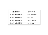
- an operation instruction table 11b is set in which the type of reciprocating motion detected by the motion detecting means 10 is compared with the instruction content to the automobile 16 that means the reciprocating motion. For example, as shown in FIG. 4, the movement instruction table 11 b instructs the automobile 16 about the vertical and horizontal reciprocating motions of the portable device 1 and the vertical and horizontal reciprocating motions of the parallel movement. Instruction contents are set.
- the operation instruction means 11 is a content that instructs the automobile 16 to release the door lock. Is read from the operation instruction table 11 b and an instruction code for instructing this operation is transmitted to the control unit 15.
- the control unit 15 is a main control unit of the automobile 16 composed of a CPU, and performs control processing of electronic devices mounted on the automobile 16 based on execution of predetermined software.
- FIG. 1 only the portable device recognition means 24 directly related to the operation of the electronic key system 100 according to the present invention is shown, but this function is also realized by executing this software.
- the portable device recognition means 24 intermittently transmits a request signal for requesting the portable device 1 to transmit an ID from the wireless communication device 14. Then, when the portable device 1 that falls within the range of the request signal receives the request signal by the wireless communication device 6 and sends an ID in response thereto, the portable device recognition means 24 compares it with the preset ID. If they match, the presence of the portable device 1 is recognized.
- the control unit 15 receives a door lock driving device mounted on the automobile 16 according to the content of the command code. 17, the engine drive device 18, the steering lock drive device 19 and the like are driven.
- the portable device 1 When the bracelet 20 is wound around the user's arm and worn, and the buckle 22 is locked, the portable device 1 is operated by receiving an attachment signal from the attachment / detachment detection sensor 4 (step 7). S1).
- control part 7 discriminate
- the biological recognition sensor 2 outputs biological information based on the fingerprint, but until the biological recognition sensor 2 outputs the biological information.
- a mounting release signal is input from the attachment / detachment detection sensor 4 (“YES” in step S3)
- the control unit 7 ends the operation. This is an operation when the portable device 1 is worn by the user, but the portable device 1 is removed from the arm without placing a fingertip on the package surface of the portable device 1.
- the biometric authentication unit 8 collates the biometric information detected by the biometric recognition sensor 2 with the registered biometric information stored in the registered biometric information storage unit 13 and wears it. It is determined whether or not the person 23 is a previously registered user (step S4). If the collation does not match and the user is not a registered user, the process is step S10 described later.
- the biometric authentication unit 8 When the biometric authentication unit 8 confirms that the wearer 23 is a registered user by matching the biometric information (“YES” in step S4), the biometric authentication unit 8 sets an authentication flag 8a indicating that the wearer 23 is a registered user ( Step S5).
- the control unit 7 determines whether or not the communication control means 9 is wirelessly connected to the control unit 15 of the automobile 16 existing in the vicinity (step S6).
- the communication control means 9 receives a request signal transmitted from the control unit 15 by the portable device recognition means 24.
- ID is transmitted in response to this, and the portable communication recognition means 24 establishes a wireless communication connection.
- the control unit 7 and the control unit 15 is established.
- the control unit 7 determines whether or not the portable device 1 has reciprocated by the motion detection means 10 (Ste S7). At this time, when the movement detection means 10 calculates the movement position from the movement amount and movement angle of the portable device 1 output from the movement detection sensor 3, the movement amount and movement angle of the portable device 1 output from the movement detection sensor 3 next. When the movement position calculated from the above is the original position before the movement, it is determined that the movement is reciprocated. At this time, the motion detection means 10 determines the content of the reciprocating motion from the movement amount and the movement angle detected by the motion detection means 10. If there is a change in the movement angle, it is a rotational movement, and if there is no change, it becomes a parallel movement.
- the control unit 7 refers to the operation instruction table 11b based on the contents of the reciprocating motion determined by the motion detecting unit 10 by the operation instructing unit 11, and this movement is activated in the automobile 16. It is determined whether or not the movement indicates the instruction content (step S8). Then, when it is determined that the movement indicates the instruction content, the operation instruction means 11 outputs an instruction code indicating this instruction to the control unit 15 of the automobile 16 (step S9).
- the wearer 23 performs the movement indicated by the arrow a that rotates upward with the elbow of the arm wearing the portable device 1 as a fulcrum.
- the door lock release instruction code is transmitted to the control unit 15. Therefore, the control unit 15 that has received the instruction code outputs a drive signal to the door lock driving device 17 to release the door lock.
- the operation control means determines that it is a door lock instruction for the automobile 16 and transmits a door lock command code to the control unit 15. Further, in the operation instruction table 11b of this example, when the user lifts the arm wearing the portable device 1 in parallel, the movement is instructed to start the engine, and the operation instruction means 11 generates an instruction code for starting the engine. To the control unit 15 of the automobile 16.
- the control unit 7 determines whether or not an attachment release signal is output from the attachment / detachment detection sensor 4 when the instruction code is transmitted by the operation instruction unit 11 (step S10). If the mounting release signal is not output (“NO” in step S10), the control unit 7 performs the processing in steps S5 to S11 when the authentication flag 8a is set (“NO” in step S11). In the meantime, when a movement indicating the instruction content by the wearer 23 is detected in a state where wireless communication connection is possible ("YES" in step S6), an instruction code corresponding to the movement is transmitted to the control unit 15. To do.
- step S6 determines whether “NO” is determined in each determination process of steps S6, S7, and S8 described above, as long as the wearer 23 does not remove the portable device 1 from the arm and the authentication flag 8a is set. The processes from step S6 to step S11 are repeated.
- step S10 when the wearer 23 removes the portable device 1 from his / her arm and outputs an attachment release signal from the attachment / detachment detection sensor 4 (“YES” in step S10), the control unit 7 resets the authentication flag 8a. The operation is terminated (step S12). Therefore, the authentication between the portable device 1 and the control unit 15 is released.
- step S10 the authentication flag 8a is not set in this case. Since it is a set, the control part 7 complete
- the user's specific movement is detected on the portable device 1 side, and the instruction code to the automobile 16 corresponding to this movement is output, but the user's specific movement is detected on the automobile 16 side.
- FIG. 6 conceptually shows a block diagram of the entire configuration of the electronic key system 200 according to such an embodiment.
- the operation of the electronic key system 200 will be described.
- the components common to the electronic key system 100 are denoted by the same reference numerals, and detailed description thereof will be omitted.
- an imaging device is disposed at a position where the movement of the user's hand in the vicinity of the steering handle of the automobile 16 can be imaged, for example, a ceiling portion in the vehicle.
- an imaging apparatus by capturing the movement of the hand using the stereo camera 25, the movement of the hand can be accurately captured by recognizing the shape, distance, and position of the captured hand in three dimensions.
- the control unit 15A is a main control unit of the automobile 16 composed of a CPU, and performs control processing of electronic equipment mounted on the automobile 16 based on execution of predetermined software.
- FIG. 6 shows only the portable device recognition unit 24, the image recognition unit 32, and the operation control unit 33, which are directly related to the operation of the electronic key system 200, but these functions are realized by executing this software. Is done.
- the portable device recognition means 24 also intermittently transmits a request signal for requesting transmission of an ID to the portable device 1 from the wireless communication device 14 in the same manner as described above for the electronic key system 100, and the range of the request signal.
- the portable device 1 that has entered the mobile communication device 6 receives a request signal
- the ID transmitted in response to the request signal is compared with a preset ID, and if they match, the wireless communication connection is established. Establish.
- the image recognition unit 32 operates the stereo camera 25 while the portable device recognition unit 24 recognizes the portable device 1. Then, image recognition processing is performed on the three-dimensional image information of the hand movement captured and output by the stereo camera 25 to detect the user's hand movement. In this process, three-dimensional image information of hand movements captured and output by the stereo camera 25 is subjected to image processing, binarized using a preset standard pattern, and then processed using a standard pattern. A well-known method for recognizing hand movement by performing pattern matching of a digitized image is used.
- the operation control means 33 operates the door lock drive device 17, the engine drive device 18, the steering lock drive device 19, the air conditioner 26, the audio device 27, etc. according to the movement of the user's hand determined by the image recognition means 32. Control.
- the operation control unit 33 outputs a drive signal to the engine drive unit 18.
- the movement and the corresponding instruction content to each part of the automobile 16 are set in the memory 34 in advance.
- such actions include moving the finger from “goo” to “choki” or “par”, and raising the thumb.
- FIG. 8 is a flowchart showing the operation of the portable device 1.
- the bracelet 20 is wound around the user's arm and worn, and the buckle 22 is locked. Is input and the operation is started (step S21).
- the control unit 7A determines whether or not biometric information is detected by the biometric recognition sensor 2 by the biometric authentication unit 8 (step S22).
- the biometric recognition sensor 2 outputs biometric information based on the fingerprint, but the biometric recognition sensor 2 outputs biometric information.
- an attachment release signal is input from the attachment / detachment detection sensor 4 (“YES” in step S23)
- the control unit 7A places the fingertip on the package surface of the portable device 1 although the portable device 1 is worn by the user. Without placing, it is determined that the portable device 1 has been removed from the arm, and the operation ends.
- the biometric authentication unit 8 collates the biometric information detected by the biometric recognition sensor 2 with the registered biometric information stored in the registered biometric information storage unit 13 and wears it. It is determined whether or not the person 23 is a previously registered user (step 24). However, when the collation does not match and the user is not a registered user, the processing of step S27 is performed, but the operation at this time will be clarified later.
- the biometric authentication unit 8 When the biometric authentication unit 8 confirms that the wearer 23 is a registered user by matching the biometric information (“YES” in step S24), the biometric authentication unit 8 sets an authentication flag 8a indicating that the wearer 23 is a registered user ( Step S25). Then, when the authentication flag 8a is in the set state, the control unit 7A makes a wireless communication connection with the control unit 15A of the automobile 16 possible (step S26).
- the state in which wireless communication connection is possible means that when the control unit 15A of the automobile 16 transmits a request signal by the portable device authentication means 24, the portable device 1 transmits an ID by the communication control means 9 in response thereto. It is a state that can be done.
- control unit 7A determines whether or not a mounting release signal is input from the attachment / detachment detection sensor 4 (step S27), and if not input, checks the set of the authentication flag 8a (step S28). When the flag is set, the process returns to step S26. Therefore, the control unit 7A can perform wireless communication with the control unit 15A in step S26 while the attachment release signal is not input from the attachment / detachment detection sensor 4 and the authentication flag 8a is set. It has become.
- step S27 when the wearer 23 removes the portable device 1 from his / her arm, and the attachment release signal is output from the attachment / detachment detection sensor 4 (“YES” in step S27), the control unit 7A resets the authentication flag 8a. The operation is terminated (step S29). Therefore, wireless communication is disabled by resetting the authentication flag 8a.
- step S24 the operation of the control unit 7A when it is determined in step S24 that biometric information collation does not match and the wearer is not a registered user will be described.
- the authentication flag 8a is not set, and the process of step S27 is performed in a state where wireless communication with the control unit 15A is not possible.
- the control unit 7A ends the operation (in step S28). "YES"). Therefore, even if a user without authority wears the portable device 1, the control unit 7A does not perform wireless communication with the control unit 15A.
- FIG. 9A is a flowchart showing the “portable device recognition” operation of the control unit 15A.
- the control unit 15A transmits a request signal for requesting an ID to the portable device 1 by the portable device recognition means 24 (step S41).
- step S26 the control unit 7A performs the process of step S26 (FIG. 8). Then, a preset ID is transmitted from the wireless communication device 6. Therefore, when the ID is transmitted, the portable device recognition means 24 determines whether or not this ID matches a preset ID (step S42). If the ID matches, the presence of the portable device 1 exists. Is recognized (step S43). As a result, authentication between the control unit 7A and the control unit 15A is established.
- control unit 15A outputs a door lock release signal to the door lock drive device 17 to release the door lock (step S44), drives the stereo camera 25, and ends the routine of the portable device recognition process.
- control unit 15 ⁇ / b> A executes a control process for a predetermined electronic device mounted on the automobile 16, while a timer interrupt causes a “ The image recognition process is performed.
- the control unit 15A determines whether the communication connection with the portable device 1 is possible by the portable device recognition means 24 (step S51). In this case, it is determined whether or not an ID is transmitted from the portable device 1 in response to the transmission of the request signal by the portable device recognition means 24. As described above, the portable device 1 can establish a wireless communication connection when the authentication flag 8a is set.
- the control unit 15A detects the movement of the user's hand from the image captured and output by the stereo camera 25 by the image recognition means 32 (step S52). Then, the motion control means 33 determines whether or not the detected hand movement is a content for instructing each part of the automobile 16 (step S53). After outputting the drive signal to the component, the process returns to the process before the interruption (step S54). Accordingly, for example, an ON / OFF signal or a temperature adjustment signal is output to the air conditioner 26, and a volume adjustment signal is output to the audio device 27 as instructed by the user.
- step S51 if it is determined in step S51 that communication connection with the portable device 1 is impossible, the control unit 15A stops driving the stereo camera 25 (step S55). Then, the control unit 15A returns to the process before the interruption, but does not perform the “image recognition” interruption process thereafter. Thereby, when the control unit 15A recognizes the portable device 1 and releases the door lock, even if another person who does not wear the portable device 1 enters the vehicle and moves his hand, the vehicle 16 cannot be instructed. .
- the electronic key systems 100 and 200 include biometric information in which biometric information is input after a wearing signal is generated by the user wearing the portable device 1 and input biometric information is registered in advance. If they match, it is confirmed that the wearer is a user having authority registered in advance. After this confirmation, in the electronic key system 100, the user can give an instruction to the automobile 16 by the movement of the worn arm.
- the electronic key system 200 when the presence of the portable device 1 is recognized, the automobile 16 releases the door lock, and the user who has boarded the vehicle can give an instruction to the automobile 16 by making a predetermined movement with the palm of the hand. it can.
- the electronic key systems 100 and 200 described above are provided with the biometric authentication unit 8 and the registered biometric information storage unit 13 in the control units 7 and 7A of the portable device 1, but are provided in a cloud connected via a communication line such as the Internet. May be.
- FIG. 10 shows a conceptual diagram of an electronic key system 300 in which the biometric authentication means 8 and the registered biometric information storage unit 13 are provided in the cloud server 50.
- control unit 7 ⁇ / b> B of the portable device 1 detects that the portable device 1 is worn by the user by the attachment / detachment detection sensor 4, and then when the biological recognition sensor 2 detects the wearer's biological information, the cloud server 50.
- the biometric authentication unit 8 discriminates the coincidence with the biometric information of the registered user.
- the control unit 7B of the portable device 1 in order to transmit the wearer's biometric information detected by the biometric sensor 2 to the cloud server 50 via the communication line 51, the control unit 7B of the portable device 1 once transmits the biometric information to the control unit of the automobile 16.
- a method a for transferring from the control unit 7C to the cloud server 50 and a method b for the portable device 1 to directly access the cloud server 50 for transmission.
- the portable device 1 in the case of the latter method b is preferably a wireless terminal portable device such as a smartphone or a tablet computer that can be connected to the cloud server 50 via the communication line 51.
- the electronic key system 300 similarly to the electronic key systems 100 and 200, the electronic key system 300 also includes the biometric recognition sensor 2 and the attachment / detachment detection sensor 4 in the portable device 1. Then, the control unit 7C of the automobile 16 intermittently transmits a request signal for requesting the transmission of the ID to the portable device 1 from the wireless communication device 14, but the portable device 1 responds to the reception of the request signal by receiving the ID. Has the same functions as those of the electronic key systems 100 and 200.
- FIG. 11 is a sequence diagram for explaining the process until the authentication between the control unit 7B and the control unit 7C of the portable device 1 is established in the case of the method a for transferring the biological information transmitted from the portable device 1 to the cloud server 50. It is.
- the control unit 7B transmits the ID by receiving the request signal transmitted from the control unit 7C.
- the control unit 7C transmits the acquired biological information to the control unit 7C by permitting communication when the transmitted ID matches the ID stored in advance.
- the control unit 7C transfers the biometric information to the cloud server 50, and the cloud server 50 determines whether the biometric information matches the biometric information stored in the registered biometric information storage unit 13. Thereby, authentication between control unit 7C and control part 7B is materialized.
- FIG. 12 is a sequence diagram for explaining until authentication between the control unit 7B and the control unit 7C of the portable device 1 is established in the method b in which the biological information acquired by the portable device 1 is directly transmitted to the cloud server 50. It is.
- the control unit 7 ⁇ / b> B transmits the biological information to the cloud server 50 when the biological recognition sensor 2 acquires the biological information.
- the cloud server 50 determines whether or not the biometric information matches the biometric information stored in the registered biometric information storage unit 13. If the biometric information matches, the cloud server 50 transmits a match signal to the control unit 7B. Then, after inputting the coincidence signal, the control unit 7B transmits the ID by receiving the request signal transmitted from the control unit 7C.
- the control unit 7C permits authentication between the control unit 7C and the control unit 7B by permitting communication when the transmitted ID matches the ID stored in advance.
- the portable device 1 is worn as described in the electronic key system 100, although not shown.
- a command code for the automobile is transmitted to the control unit 7C by the movement of the user's part.
- the control unit 7C detects the movement of the hand of the user wearing the portable device 1, and controls the operation of the automobile according to this movement.
- the biometric information of the user registered in this way is stored in the cloud server 50, and biometric authentication is performed by the cloud server 50, whereby authentication is established with a plurality of vehicle control units using one portable device 1. It becomes possible. Therefore, in the owner of a plurality of cars, a rental car shop, etc., the troublesomeness of managing the portable device 1 for each car is eliminated.
- the cloud server 50 also has user-specific driving propensity information (calibration), such as seat position, home or work address, frequently visited places, shops, driving styles, and sleep time. -By storing information such as the distance between the preceding vehicle according to the speed and the timing for applying the brake according to the distance between the vehicles, especially in the case of a car that performs automatic driving, this information is downloaded. Thus, it is possible to automatically provide the driving state and the movement to the destination according to the user's preference.
- calibration user-specific driving propensity information
- autonomous driving is an automatic driving system that has been researched and developed in recent years to further improve road traffic safety. This system recognizes the environment around the vehicle. It runs automatically.
- the automated level of an automated driving system for vehicles such as automobiles is defined in four stages from level 1 to level 4.
- Level 1 is called a safe driving support system, where the vehicle performs acceleration, steering, or braking.
- Level 2 is called a semi-automatic driving system (semi-automatic driving), in which a vehicle performs a plurality of operations of acceleration, steering, and braking simultaneously.
- Level 3 is a state in which acceleration, steering, and braking are all performed by the vehicle and the driver responds only in an emergency. This is also called a semi-automatic driving system.
- Level 4 is called a fully automatic driving system in which acceleration, steering and braking are all performed by a person other than the driver and the driver is not involved at all.
- Levels 2 to 4 are also called automated driving systems ("Step SIP (Strategic Innovation Creation Program) Automated Driving System Research and Development Plan", November 13, 2014, Cabinet Office, Policy Director (Science Technology and innovation)). Therefore, “automatic driving” includes all automatic driving of the fully automated level from level 1 to level 4.
- the present invention is not limited to the above-described embodiments, and various modifications or changes are made within the technical scope thereof.
- the user wearing the portable device 1 is not limited to a bracelet, but may be a ring, a headband, a necklace, a pendant, or the like.
- the user's movement is not limited to the arm or palm, but may be the movement of the head.
Abstract
L'invention concerne un système de clé électronique qui permet de donner une instruction à une automobile, depuis un côté machine portable, l'authentification biométrique d'un utilisateur ayant été obtenue. Une machine portable (1) portée par l'utilisateur détermine, lorsque des informations biométriques d'un utilisateur sont détectées par un capteur de reconnaissance biométrique (2), si des informations biométriques détectées par un moyen d'authentification biométrique (8) correspondent ou non à des informations biométriques de l'utilisateur préalablement enregistré. Ensuite, lorsque le moyen d'authentification biométrique (8) vérifie que l'utilisateur est un utilisateur enregistré, la machine portable (1) permet, par un moyen de commande de communication (9), une communication radio en champ proche avec une unité de commande (15), montée dans une automobile (16), par un appareil de communication radio (6). Ainsi, la machine portable (1) peut donner une instruction d'une opération à l'automobile (16) par communication radio avec l'unité de commande (15).
Priority Applications (3)
| Application Number | Priority Date | Filing Date | Title |
|---|---|---|---|
| EP16841517.2A EP3342651A4 (fr) | 2015-08-28 | 2016-08-18 | Système de clé électronique |
| CN201680050100.2A CN107921927A (zh) | 2015-08-28 | 2016-08-18 | 电子钥匙系统 |
| US15/755,369 US10384647B2 (en) | 2015-08-28 | 2016-08-18 | Electronic key system |
Applications Claiming Priority (2)
| Application Number | Priority Date | Filing Date | Title |
|---|---|---|---|
| JP2015168531A JP2017043267A (ja) | 2015-08-28 | 2015-08-28 | 電子キーシステム |
| JP2015-168531 | 2015-08-28 |
Publications (1)
| Publication Number | Publication Date |
|---|---|
| WO2017038485A1 true WO2017038485A1 (fr) | 2017-03-09 |
Family
ID=58187475
Family Applications (1)
| Application Number | Title | Priority Date | Filing Date |
|---|---|---|---|
| PCT/JP2016/074125 WO2017038485A1 (fr) | 2015-08-28 | 2016-08-18 | Système de clé électronique |
Country Status (5)
| Country | Link |
|---|---|
| US (1) | US10384647B2 (fr) |
| EP (1) | EP3342651A4 (fr) |
| JP (1) | JP2017043267A (fr) |
| CN (1) | CN107921927A (fr) |
| WO (1) | WO2017038485A1 (fr) |
Cited By (2)
| Publication number | Priority date | Publication date | Assignee | Title |
|---|---|---|---|---|
| CN107669252A (zh) * | 2017-11-09 | 2018-02-09 | 京东方科技集团股份有限公司 | 一种可穿戴设备及其控制方法 |
| CN110386106A (zh) * | 2018-04-20 | 2019-10-29 | 比亚迪股份有限公司 | 防止终端设备遗落在车辆的方法、装置、系统和车辆 |
Families Citing this family (20)
| Publication number | Priority date | Publication date | Assignee | Title |
|---|---|---|---|---|
| DE102015225778A1 (de) * | 2015-12-17 | 2017-06-22 | Deutsche Post Ag | Vorrichtung und Verfahren für die personalisierte Bereitstellung eines Schlüssels |
| US10053056B1 (en) | 2017-04-20 | 2018-08-21 | Denso International America, Inc. | Multi-step vehicle entry authorization |
| DE102017120778A1 (de) * | 2017-09-08 | 2019-03-14 | Connaught Electronics Ltd. | Verfahren zum autonomen Parken eines aktuellen Fahrzeugs entlang einer trainierten Trajektorie |
| JP6984281B2 (ja) | 2017-09-27 | 2021-12-17 | トヨタ自動車株式会社 | 車両状態提示システム、車両、端末装置、および、方法 |
| JP6915481B2 (ja) | 2017-09-27 | 2021-08-04 | トヨタ自動車株式会社 | 車両制御システム |
| KR102388273B1 (ko) * | 2017-10-24 | 2022-04-20 | 아싸 아브로이 에이비 | 다중 생체인식을 포함하는 웨어러블 디바이스 |
| EP3476672A1 (fr) * | 2017-10-27 | 2019-05-01 | Continental Automotive GmbH | Unité d'émetteur mobile et procédé pour commander une fonction d'un système technique utilisant une telle unité d'émetteur mobile |
| JP2019097024A (ja) * | 2017-11-22 | 2019-06-20 | クラリオン株式会社 | 遠隔操作システム、車載装置、及び遠隔操作方法 |
| JP7114933B2 (ja) * | 2018-03-01 | 2022-08-09 | 株式会社デンソー | ウェアラブルキーデバイス、及び電子キーシステム |
| US10529085B2 (en) * | 2018-03-30 | 2020-01-07 | Samsung Electronics Co., Ltd. | Hardware disparity evaluation for stereo matching |
| US10587613B2 (en) | 2018-06-18 | 2020-03-10 | DataLogic Software, Inc. | Systems and methods for one-time password authentication |
| KR102564019B1 (ko) * | 2018-07-03 | 2023-08-07 | 현대자동차주식회사 | 반지형 무선 컨트롤러 및 그의 작동 방법 |
| JP7154061B2 (ja) * | 2018-08-07 | 2022-10-17 | 株式会社東海理化電機製作所 | 生体情報認証装置 |
| CN109446767A (zh) * | 2018-09-29 | 2019-03-08 | 东风汽车有限公司 | 车辆人员身份安全验证方法、设备及系统 |
| KR20200057979A (ko) * | 2018-11-19 | 2020-05-27 | 현대자동차주식회사 | 차량 및 차량의 제어방법 |
| JP2020201805A (ja) * | 2019-06-12 | 2020-12-17 | 国立大学法人福井大学 | 認証プログラム、認証装置及び認証システム |
| KR20210031267A (ko) | 2019-09-11 | 2021-03-19 | 삼성전자주식회사 | 인증을 수행하는 차량용 전자 기기, 차량 인증에 이용되는 모바일 기기, 차량 인증 시스템, 및 차량의 인증 방법 |
| CN111083670A (zh) * | 2019-12-31 | 2020-04-28 | 东风小康汽车有限公司重庆分公司 | 一种基于智能钥匙的车辆使用方法及装置 |
| CN112896387B (zh) * | 2021-02-09 | 2022-12-13 | 常州高翎未来科技有限公司 | 骑行交通工具的控制方法、装置和电子设备 |
| CN116101220A (zh) * | 2023-02-24 | 2023-05-12 | 英华达(上海)科技有限公司 | 汽车解锁控制方法、系统、设备及存储介质 |
Citations (4)
| Publication number | Priority date | Publication date | Assignee | Title |
|---|---|---|---|---|
| JP2005139700A (ja) * | 2003-11-06 | 2005-06-02 | Fuji Heavy Ind Ltd | キーレスエントリ装置 |
| JP2008189261A (ja) * | 2007-02-07 | 2008-08-21 | Quality Kk | 車両管理システムおよび資格管理プログラム |
| JP2014148842A (ja) * | 2013-02-01 | 2014-08-21 | Tokai Rika Co Ltd | 車両扉開閉装置 |
| JP2015074311A (ja) * | 2013-10-08 | 2015-04-20 | 株式会社東海理化電機製作所 | 動作検知リモートシステム |
Family Cites Families (37)
| Publication number | Priority date | Publication date | Assignee | Title |
|---|---|---|---|---|
| JP4126385B2 (ja) * | 1998-12-31 | 2008-07-30 | カシオ計算機株式会社 | 身体装着機器及び認証システム |
| US20140070943A1 (en) * | 2002-06-11 | 2014-03-13 | Intelligent Technologies International, Inc. | Atmospheric and Chemical Monitoring Techniques |
| JP2004216125A (ja) * | 2002-11-19 | 2004-08-05 | Seiko Instruments Inc | 生体情報検出端末制御システム |
| CN1742146A (zh) * | 2002-12-13 | 2006-03-01 | 松下电器产业株式会社 | 车载设备控制系统、车载设备控制装置以及车载设备控制方法 |
| JP4633347B2 (ja) * | 2003-08-27 | 2011-02-16 | ソニー株式会社 | 電子機器 |
| US7259653B2 (en) | 2003-11-06 | 2007-08-21 | Fuji Jukogyo Kabushiki Kaisha | Keyless entry device |
| KR100608595B1 (ko) * | 2004-11-16 | 2006-08-03 | 삼성전자주식회사 | 얼굴 인식 방법 및 장치 |
| JP4604776B2 (ja) * | 2005-03-15 | 2011-01-05 | トヨタ自動車株式会社 | 遠隔制御装置 |
| JP4843389B2 (ja) * | 2006-06-28 | 2011-12-21 | 本田技研工業株式会社 | 生体認証システム |
| US20100039224A1 (en) * | 2008-05-26 | 2010-02-18 | Okude Kazuhiro | Biometrics information matching apparatus, biometrics information matching system, biometrics information matching method, person authentication apparatus, and person authentication method |
| JP2009286343A (ja) * | 2008-05-30 | 2009-12-10 | Fujitsu Ten Ltd | 遠隔車両制御システム、乗員認証装置および遠隔車両制御方法 |
| JP4636171B2 (ja) * | 2008-12-17 | 2011-02-23 | トヨタ自動車株式会社 | 車両用生体認証システム |
| US8258919B2 (en) * | 2010-03-05 | 2012-09-04 | International Business Machines Corporation | Mobile device communications management |
| US10042993B2 (en) * | 2010-11-02 | 2018-08-07 | Homayoon Beigi | Access control through multifactor authentication with multimodal biometrics |
| US8737913B2 (en) * | 2010-12-22 | 2014-05-27 | Verizon Patent And Licensing Inc. | Methods and systems for providing a wireless automobile key service |
| JP5432192B2 (ja) * | 2011-01-12 | 2014-03-05 | 株式会社東海理化電機製作所 | 電子キーシステム |
| EP2738337B1 (fr) * | 2011-07-29 | 2017-06-21 | Panasonic Intellectual Property Management Co., Ltd. | Appareil pour commander un élément d'ouverture/de fermeture de véhicule |
| FR2981767B1 (fr) * | 2011-10-21 | 2014-07-04 | Continental Automotive France | Procede et dispositif de communication entre un vehicule automobile et des moyens de paiement |
| EP2805311A4 (fr) * | 2012-01-20 | 2015-10-07 | Thomson Licensing | Procédé et appareil pour la reconnaissance d'un utilisateur |
| JP2014151884A (ja) * | 2013-02-13 | 2014-08-25 | Toyota Motor Corp | 通信システム、車載機及び携帯機並びに通信方法 |
| JP2014200165A (ja) * | 2013-03-14 | 2014-10-23 | 株式会社リコー | 調停装置、調停方法およびプログラム |
| JP6111133B2 (ja) * | 2013-04-23 | 2017-04-05 | 株式会社東海理化電機製作所 | 遠隔操作システム |
| US20140359499A1 (en) * | 2013-05-02 | 2014-12-04 | Frank Cho | Systems and methods for dynamic user interface generation and presentation |
| US9485607B2 (en) * | 2013-05-14 | 2016-11-01 | Nokia Technologies Oy | Enhancing the security of short-range communication in connection with an access control device |
| US9013300B2 (en) * | 2013-06-12 | 2015-04-21 | Wilfredo FELIX | Method of communicating information through a wearable device |
| US20150025917A1 (en) * | 2013-07-15 | 2015-01-22 | Advanced Insurance Products & Services, Inc. | System and method for determining an underwriting risk, risk score, or price of insurance using cognitive information |
| US9558336B2 (en) * | 2013-10-04 | 2017-01-31 | Salutron Inc. | Persistent authentication using sensors of a user-wearable device |
| US9499125B2 (en) * | 2013-10-29 | 2016-11-22 | Volkswagen Aktiengesellschaft | Vehicle system for activating a vehicle component to provide vehicle access |
| US10088844B2 (en) * | 2013-11-22 | 2018-10-02 | Ford Global Technologies, Llc | Wearable computer in an autonomous vehicle |
| WO2015101210A1 (fr) * | 2013-12-31 | 2015-07-09 | 马要武 | Clés et verrous |
| JP2015153258A (ja) * | 2014-02-17 | 2015-08-24 | パナソニックIpマネジメント株式会社 | 車両用個人認証システム及び車両用個人認証方法 |
| US20150288687A1 (en) * | 2014-04-07 | 2015-10-08 | InvenSense, Incorporated | Systems and methods for sensor based authentication in wearable devices |
| US9491171B2 (en) * | 2014-04-16 | 2016-11-08 | iAccess Technologies Inc. | System and method for vascular mapping authentication |
| KR102302350B1 (ko) * | 2014-06-02 | 2021-09-15 | 삼성전자 주식회사 | 보안 기능을 제공하는 방법 및 장치 |
| KR102443186B1 (ko) * | 2014-06-11 | 2022-09-14 | 베라디움 아이피 리미티드 | 생체 인식 정보에 기반된 차량들에 대한 유저 액세스를 가능하게 하기 위한 시스템 및 방법 |
| US9690387B2 (en) * | 2014-06-13 | 2017-06-27 | Ford Global Technologies, Llc | Vehicle computing system in communication with a wearable device |
| US9674700B2 (en) * | 2014-11-04 | 2017-06-06 | Qualcomm Incorporated | Distributing biometric authentication between devices in an ad hoc network |
-
2015
- 2015-08-28 JP JP2015168531A patent/JP2017043267A/ja active Pending
-
2016
- 2016-08-18 WO PCT/JP2016/074125 patent/WO2017038485A1/fr active Application Filing
- 2016-08-18 CN CN201680050100.2A patent/CN107921927A/zh active Pending
- 2016-08-18 US US15/755,369 patent/US10384647B2/en not_active Expired - Fee Related
- 2016-08-18 EP EP16841517.2A patent/EP3342651A4/fr not_active Withdrawn
Patent Citations (4)
| Publication number | Priority date | Publication date | Assignee | Title |
|---|---|---|---|---|
| JP2005139700A (ja) * | 2003-11-06 | 2005-06-02 | Fuji Heavy Ind Ltd | キーレスエントリ装置 |
| JP2008189261A (ja) * | 2007-02-07 | 2008-08-21 | Quality Kk | 車両管理システムおよび資格管理プログラム |
| JP2014148842A (ja) * | 2013-02-01 | 2014-08-21 | Tokai Rika Co Ltd | 車両扉開閉装置 |
| JP2015074311A (ja) * | 2013-10-08 | 2015-04-20 | 株式会社東海理化電機製作所 | 動作検知リモートシステム |
Non-Patent Citations (1)
| Title |
|---|
| See also references of EP3342651A4 * |
Cited By (2)
| Publication number | Priority date | Publication date | Assignee | Title |
|---|---|---|---|---|
| CN107669252A (zh) * | 2017-11-09 | 2018-02-09 | 京东方科技集团股份有限公司 | 一种可穿戴设备及其控制方法 |
| CN110386106A (zh) * | 2018-04-20 | 2019-10-29 | 比亚迪股份有限公司 | 防止终端设备遗落在车辆的方法、装置、系统和车辆 |
Also Published As
| Publication number | Publication date |
|---|---|
| JP2017043267A (ja) | 2017-03-02 |
| CN107921927A (zh) | 2018-04-17 |
| US10384647B2 (en) | 2019-08-20 |
| US20180272991A1 (en) | 2018-09-27 |
| EP3342651A1 (fr) | 2018-07-04 |
| EP3342651A4 (fr) | 2019-04-17 |
Similar Documents
| Publication | Publication Date | Title |
|---|---|---|
| WO2017038485A1 (fr) | Système de clé électronique | |
| US11052874B2 (en) | Recognizing authorized vehicle user with movement data | |
| JP6609005B2 (ja) | 自動車及び自動車用プログラム | |
| JP6810607B2 (ja) | 自動車両の自動移動操縦を制御するための方法 | |
| CN108327722B (zh) | 用于通过移动模式来识别车辆驾驶员的系统和方法 | |
| KR102303556B1 (ko) | 기기 제어 장치 | |
| US20230350498A1 (en) | Human-machine interaction method and human-machine interaction apparatus | |
| CN112238832A (zh) | 一种车辆座舱偏好设置实现方法、系统及存储介质 | |
| JP2023086816A (ja) | 自動車及び歩容認識システム | |
| CN110794819A (zh) | 一种手势按键融合的智能汽车无线驾驶控制系统 | |
| JP2019049875A (ja) | 作動許可認証装置 | |
| US11951941B2 (en) | Methods and apparatus for enabling contactless command of a vehicle | |
| US11055999B2 (en) | Vehicle control apparatus, vehicle control method, and storage medium | |
| CN113799733A (zh) | 用于从车辆外部控制车辆的方法、控制装置、系统和车辆 | |
| US10870436B2 (en) | Operation assistance system and operation assistance method | |
| WO2019181143A1 (fr) | Système de commande de véhicule | |
| US20240095317A1 (en) | Method and System For Device Access Control | |
| KR101986605B1 (ko) | 위치기반 자전거 잠금/해제 시스템 | |
| JP2019097024A (ja) | 遠隔操作システム、車載装置、及び遠隔操作方法 | |
| WO2021131194A1 (fr) | Système d'authentification, dispositif de commande et support non transitoire lisible par ordinateur | |
| JP2023114459A (ja) | ドライバ推定装置、制御方法、プログラム及び記憶媒体 | |
| JP2021179893A (ja) | 認証システム、制御装置、およびコンピュータプログラム | |
| JP2021117669A (ja) | 生体認証システム、制御装置、およびコンピュータプログラム | |
| JP2020076271A (ja) | 車両用自動開扉装置およびプログラム |
Legal Events
| Date | Code | Title | Description |
|---|---|---|---|
| 121 | Ep: the epo has been informed by wipo that ep was designated in this application |
Ref document number: 16841517 Country of ref document: EP Kind code of ref document: A1 |
|
| WWE | Wipo information: entry into national phase |
Ref document number: 15755369 Country of ref document: US |
|
| NENP | Non-entry into the national phase |
Ref country code: DE |
|
| WWE | Wipo information: entry into national phase |
Ref document number: 2016841517 Country of ref document: EP |