WO2017038485A1 - Electronic key system - Google Patents
Electronic key system Download PDFInfo
- Publication number
- WO2017038485A1 WO2017038485A1 PCT/JP2016/074125 JP2016074125W WO2017038485A1 WO 2017038485 A1 WO2017038485 A1 WO 2017038485A1 JP 2016074125 W JP2016074125 W JP 2016074125W WO 2017038485 A1 WO2017038485 A1 WO 2017038485A1
- Authority
- WO
- WIPO (PCT)
- Prior art keywords
- portable device
- user
- control unit
- biometric
- authentication
- Prior art date
Links
Images


Classifications
-
- B—PERFORMING OPERATIONS; TRANSPORTING
- B60—VEHICLES IN GENERAL
- B60R—VEHICLES, VEHICLE FITTINGS, OR VEHICLE PARTS, NOT OTHERWISE PROVIDED FOR
- B60R25/00—Fittings or systems for preventing or indicating unauthorised use or theft of vehicles
- B60R25/20—Means to switch the anti-theft system on or off
- B60R25/25—Means to switch the anti-theft system on or off using biometry
- B60R25/252—Fingerprint recognition
-
- A—HUMAN NECESSITIES
- A61—MEDICAL OR VETERINARY SCIENCE; HYGIENE
- A61B—DIAGNOSIS; SURGERY; IDENTIFICATION
- A61B5/00—Measuring for diagnostic purposes; Identification of persons
- A61B5/117—Identification of persons
- A61B5/1171—Identification of persons based on the shapes or appearances of their bodies or parts thereof
- A61B5/1172—Identification of persons based on the shapes or appearances of their bodies or parts thereof using fingerprinting
-
- B—PERFORMING OPERATIONS; TRANSPORTING
- B60—VEHICLES IN GENERAL
- B60R—VEHICLES, VEHICLE FITTINGS, OR VEHICLE PARTS, NOT OTHERWISE PROVIDED FOR
- B60R25/00—Fittings or systems for preventing or indicating unauthorised use or theft of vehicles
- B60R25/20—Means to switch the anti-theft system on or off
- B60R25/24—Means to switch the anti-theft system on or off using electronic identifiers containing a code not memorised by the user
-
- B—PERFORMING OPERATIONS; TRANSPORTING
- B60—VEHICLES IN GENERAL
- B60R—VEHICLES, VEHICLE FITTINGS, OR VEHICLE PARTS, NOT OTHERWISE PROVIDED FOR
- B60R25/00—Fittings or systems for preventing or indicating unauthorised use or theft of vehicles
- B60R25/20—Means to switch the anti-theft system on or off
- B60R25/25—Means to switch the anti-theft system on or off using biometry
-
- E—FIXED CONSTRUCTIONS
- E05—LOCKS; KEYS; WINDOW OR DOOR FITTINGS; SAFES
- E05B—LOCKS; ACCESSORIES THEREFOR; HANDCUFFS
- E05B49/00—Electric permutation locks; Circuits therefor ; Mechanical aspects of electronic locks; Mechanical keys therefor
-
- G—PHYSICS
- G06—COMPUTING; CALCULATING OR COUNTING
- G06F—ELECTRIC DIGITAL DATA PROCESSING
- G06F21/00—Security arrangements for protecting computers, components thereof, programs or data against unauthorised activity
- G06F21/30—Authentication, i.e. establishing the identity or authorisation of security principals
- G06F21/31—User authentication
- G06F21/32—User authentication using biometric data, e.g. fingerprints, iris scans or voiceprints
Definitions
- the present invention relates to an electronic key system, and more particularly to an electronic key system that allows an authorized user to give an operation instruction to a vehicle.
- detachable data storage means for storing biometric information of a registrant as registration data is set in the vehicle body, and a biometric sample collected from a passenger in a car
- a key system based on biometric authentication that enables opening / closing and operation of a door lock when the information matches registered data is disclosed (see, for example, Patent Document 1).
- the present invention provides an electronic key system that makes it possible to give instructions to a vehicle from a portable device that has been authenticated by a user.
- the electronic key system of the present invention is an electronic key system that instructs a control unit mounted on an automobile to operate by a portable device that is carried when the user wears it on the body, and stores biometric information of the user registered in advance.
- the portable device includes an attachment / detachment detection unit, and the biometric authentication unit determines whether the biometric information matches when the attachment / detachment detection unit detects wearing, and the portable device indicates that they match. And authentication between the control unit and the control unit.
- the biometric authentication unit may cancel the authentication when the attachment / detachment detection unit detects that the user has detached the portable device after the authentication is established. Thereby, only the wearer of a portable machine can give directions to a car.
- the portable device detects movement of a part where the user wears the portable machine, and when the movement detection means detects a specific movement of the part, the portable device moves to the automobile corresponding to the movement. It is good to provide the operation instruction
- control unit includes a portable device recognition unit that recognizes the portable device in which the wearer is confirmed to be a registered user by the biometric authentication unit, an imaging device that images the movement of the user, and the imaging An image recognition unit that detects a specific movement of the user based on imaging information from a unit, and an operation control unit that controls the operation of the automobile according to the detected specific movement.
- an instruction can be given to the automobile by performing image recognition processing of the movement of the registered user having authority.
- biometric information storage means and the biometric authentication means may each be provided in a cloud server.
- the control unit establishes authentication with the portable device based on the determination result of the biometric authentication unit by transferring the biological information transmitted from the portable device to the cloud server. be able to.
- the portable device can transmit the biometric information to the cloud server, and can establish authentication with the control unit based on the determination result of the biometric authentication means.
- a cloud server it is possible to establish authentication with the control units of a plurality of automobiles with a single portable device.
- the control unit can authenticate with the portable device.
- the propensity information can be downloaded. Thereby, the control unit can control operation
- the electronic key system of the present invention by obtaining the user's biometric information on the portable device side, there is no need to provide a plurality of biometric recognition sensors in the car according to the instructed item, which is simplified.
- An electronic key system based on biometric authentication is provided.
- FIG. 1 shows a block diagram of an overall configuration of an electronic key system according to a first embodiment of the present invention.
- One structural example of a bracelet-type portable device is shown in an external view.
- indication to a motor vehicle by the motion of the arm which wore the portable machine is shown.
- 2 is a flowchart of the operation of the portable device in the electronic key system of FIG.
- the block diagram of the whole structure of the electronic key system by the 2nd Embodiment of this invention is shown.
- indication to a motor vehicle is shown.
- FIG. 7 is a flowchart of the operation of the portable device in the electronic key system of FIG. 7 shows a flowchart of the operation of the control unit of the automobile in the electronic key system of FIG.
- An electronic key system by a 3rd embodiment of the present invention is a conceptual explanatory view.
- FIG. 11 shows a sequence diagram until authentication between the portable device and the automobile in the electronic key system of FIG. 10 is established.
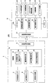
- FIG. 1 conceptually shows the entire configuration of the electronic key system 100 in a block diagram.
- the electronic key system 100 is a system for instructing an operation to the automobile 16 by wireless, and includes a portable device 1 carried by a user and a control unit 15 mounted on the automobile 16.
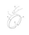
- the portable device 1 is attached to the bracelet 20 so that the user can wear it on the arm as shown in FIGS.
- the portable device 1 includes a biological recognition sensor 2, a motion detection sensor 3, an attachment / detachment detection sensor 4 that detects attachment / detachment of the bracelet 20 to a user, a registration instruction device 5, a wireless communication device 6, and a control unit 7. Composed.
- the biometric sensor 2 detects user biometric information such as fingerprints, finger vein patterns, and heartbeats.
- the biometric recognition sensor 2 in this example is a fingerprint sensor. When the fingerprint portion at the tip of a human finger 23 is pressed against the surface of the portable device 1, the fingerprint is detected as biometric information.
- the movement detection sensor 3 detects the movement amount and movement angle of the portable device 1 due to the movement of the arm of the user wearing the portable device 1.
- a motion detection sensor 3 an acceleration sensor and / or an angular velocity sensor are used.
- both the acceleration sensor and the angular velocity sensor are used to detect a movement amount and an angular velocity in three axes. .
- the attachment / detachment detection sensor 4 outputs a mounting signal when the bracelet 20 is worn on the user's arm and both ends thereof are coupled by the buckle 22, and a mounting release signal when the coupling is released.
- the wireless communication device 6 wirelessly communicates with the control unit 15 of the automobile 16 at a short distance in the RF band. In this case, when the control unit 15 determines that the portable device 1 existing in the wireless communication range is registered in advance, wireless communication is possible.
- the control unit 7 includes a computer including a CPU, a ROM, and a RAM.
- Each of the biometric authentication unit 8, the communication control unit 9, the motion detection unit 10, the operation instruction unit 11, and the biometric information registration unit 12 is performed by the CPU. This is realized by processing a control program stored in the ROM.
- the control part 7 is provided with the registration biometric information storage part 13 by the flash memory which has memorize
- the biometric information registration unit 12 stores the biometric information (in this example, fingerprint information) detected by the biometric recognition sensor 2 in the registered biometric information storage unit 13 using a flash memory. Store. In this case, a plurality of pieces of biological information can be registered in the registered biological information storage unit 13.
- the registration instruction device 5 is configured by a switch device that outputs a registration instruction signal by a predetermined operation by a registrant.
- the registration instruction device 5 is usually provided separately from the portable device 1 from the viewpoint of security. Therefore, it is preferable that the mobile phone 1 is used by being connected at the time of registration setting.
- the biometric authentication unit 8 detects the detected biometric information and the registered biometric information stored in the registered biometric information storage unit 13. Are compared to determine whether or not they match each other. If they match, the authentication flag 8a provided in the RAM is set.
- the communication control means 9 exchanges signals for inter-device authentication between the portable device 1 and the control unit 15 of the automobile 16.
- FIG. 3 schematically shows a state when the wearer 23 rotates the arm up and down in the arrow direction a with the elbow as a fulcrum.
- the operation instructing means 11 discriminates the content of an instruction given to the automobile 16 set in advance according to the reciprocating motion detected by the motion detecting means 10, generates a command code indicating the instruction, and generates a command code.
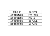
- an operation instruction table 11b is set in which the type of reciprocating motion detected by the motion detecting means 10 is compared with the instruction content to the automobile 16 that means the reciprocating motion. For example, as shown in FIG. 4, the movement instruction table 11 b instructs the automobile 16 about the vertical and horizontal reciprocating motions of the portable device 1 and the vertical and horizontal reciprocating motions of the parallel movement. Instruction contents are set.
- the operation instruction means 11 is a content that instructs the automobile 16 to release the door lock. Is read from the operation instruction table 11 b and an instruction code for instructing this operation is transmitted to the control unit 15.
- the control unit 15 is a main control unit of the automobile 16 composed of a CPU, and performs control processing of electronic devices mounted on the automobile 16 based on execution of predetermined software.
- FIG. 1 only the portable device recognition means 24 directly related to the operation of the electronic key system 100 according to the present invention is shown, but this function is also realized by executing this software.
- the portable device recognition means 24 intermittently transmits a request signal for requesting the portable device 1 to transmit an ID from the wireless communication device 14. Then, when the portable device 1 that falls within the range of the request signal receives the request signal by the wireless communication device 6 and sends an ID in response thereto, the portable device recognition means 24 compares it with the preset ID. If they match, the presence of the portable device 1 is recognized.
- the control unit 15 receives a door lock driving device mounted on the automobile 16 according to the content of the command code. 17, the engine drive device 18, the steering lock drive device 19 and the like are driven.
- the portable device 1 When the bracelet 20 is wound around the user's arm and worn, and the buckle 22 is locked, the portable device 1 is operated by receiving an attachment signal from the attachment / detachment detection sensor 4 (step 7). S1).
- control part 7 discriminate
- the biological recognition sensor 2 outputs biological information based on the fingerprint, but until the biological recognition sensor 2 outputs the biological information.
- a mounting release signal is input from the attachment / detachment detection sensor 4 (“YES” in step S3)
- the control unit 7 ends the operation. This is an operation when the portable device 1 is worn by the user, but the portable device 1 is removed from the arm without placing a fingertip on the package surface of the portable device 1.
- the biometric authentication unit 8 collates the biometric information detected by the biometric recognition sensor 2 with the registered biometric information stored in the registered biometric information storage unit 13 and wears it. It is determined whether or not the person 23 is a previously registered user (step S4). If the collation does not match and the user is not a registered user, the process is step S10 described later.
- the biometric authentication unit 8 When the biometric authentication unit 8 confirms that the wearer 23 is a registered user by matching the biometric information (“YES” in step S4), the biometric authentication unit 8 sets an authentication flag 8a indicating that the wearer 23 is a registered user ( Step S5).
- the control unit 7 determines whether or not the communication control means 9 is wirelessly connected to the control unit 15 of the automobile 16 existing in the vicinity (step S6).
- the communication control means 9 receives a request signal transmitted from the control unit 15 by the portable device recognition means 24.
- ID is transmitted in response to this, and the portable communication recognition means 24 establishes a wireless communication connection.
- the control unit 7 and the control unit 15 is established.
- the control unit 7 determines whether or not the portable device 1 has reciprocated by the motion detection means 10 (Ste S7). At this time, when the movement detection means 10 calculates the movement position from the movement amount and movement angle of the portable device 1 output from the movement detection sensor 3, the movement amount and movement angle of the portable device 1 output from the movement detection sensor 3 next. When the movement position calculated from the above is the original position before the movement, it is determined that the movement is reciprocated. At this time, the motion detection means 10 determines the content of the reciprocating motion from the movement amount and the movement angle detected by the motion detection means 10. If there is a change in the movement angle, it is a rotational movement, and if there is no change, it becomes a parallel movement.
- the control unit 7 refers to the operation instruction table 11b based on the contents of the reciprocating motion determined by the motion detecting unit 10 by the operation instructing unit 11, and this movement is activated in the automobile 16. It is determined whether or not the movement indicates the instruction content (step S8). Then, when it is determined that the movement indicates the instruction content, the operation instruction means 11 outputs an instruction code indicating this instruction to the control unit 15 of the automobile 16 (step S9).
- the wearer 23 performs the movement indicated by the arrow a that rotates upward with the elbow of the arm wearing the portable device 1 as a fulcrum.
- the door lock release instruction code is transmitted to the control unit 15. Therefore, the control unit 15 that has received the instruction code outputs a drive signal to the door lock driving device 17 to release the door lock.
- the operation control means determines that it is a door lock instruction for the automobile 16 and transmits a door lock command code to the control unit 15. Further, in the operation instruction table 11b of this example, when the user lifts the arm wearing the portable device 1 in parallel, the movement is instructed to start the engine, and the operation instruction means 11 generates an instruction code for starting the engine. To the control unit 15 of the automobile 16.
- the control unit 7 determines whether or not an attachment release signal is output from the attachment / detachment detection sensor 4 when the instruction code is transmitted by the operation instruction unit 11 (step S10). If the mounting release signal is not output (“NO” in step S10), the control unit 7 performs the processing in steps S5 to S11 when the authentication flag 8a is set (“NO” in step S11). In the meantime, when a movement indicating the instruction content by the wearer 23 is detected in a state where wireless communication connection is possible ("YES" in step S6), an instruction code corresponding to the movement is transmitted to the control unit 15. To do.
- step S6 determines whether “NO” is determined in each determination process of steps S6, S7, and S8 described above, as long as the wearer 23 does not remove the portable device 1 from the arm and the authentication flag 8a is set. The processes from step S6 to step S11 are repeated.
- step S10 when the wearer 23 removes the portable device 1 from his / her arm and outputs an attachment release signal from the attachment / detachment detection sensor 4 (“YES” in step S10), the control unit 7 resets the authentication flag 8a. The operation is terminated (step S12). Therefore, the authentication between the portable device 1 and the control unit 15 is released.
- step S10 the authentication flag 8a is not set in this case. Since it is a set, the control part 7 complete
- the user's specific movement is detected on the portable device 1 side, and the instruction code to the automobile 16 corresponding to this movement is output, but the user's specific movement is detected on the automobile 16 side.
- FIG. 6 conceptually shows a block diagram of the entire configuration of the electronic key system 200 according to such an embodiment.
- the operation of the electronic key system 200 will be described.
- the components common to the electronic key system 100 are denoted by the same reference numerals, and detailed description thereof will be omitted.
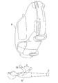
- an imaging device is disposed at a position where the movement of the user's hand in the vicinity of the steering handle of the automobile 16 can be imaged, for example, a ceiling portion in the vehicle.
- an imaging apparatus by capturing the movement of the hand using the stereo camera 25, the movement of the hand can be accurately captured by recognizing the shape, distance, and position of the captured hand in three dimensions.
- the control unit 15A is a main control unit of the automobile 16 composed of a CPU, and performs control processing of electronic equipment mounted on the automobile 16 based on execution of predetermined software.
- FIG. 6 shows only the portable device recognition unit 24, the image recognition unit 32, and the operation control unit 33, which are directly related to the operation of the electronic key system 200, but these functions are realized by executing this software. Is done.
- the portable device recognition means 24 also intermittently transmits a request signal for requesting transmission of an ID to the portable device 1 from the wireless communication device 14 in the same manner as described above for the electronic key system 100, and the range of the request signal.
- the portable device 1 that has entered the mobile communication device 6 receives a request signal
- the ID transmitted in response to the request signal is compared with a preset ID, and if they match, the wireless communication connection is established. Establish.
- the image recognition unit 32 operates the stereo camera 25 while the portable device recognition unit 24 recognizes the portable device 1. Then, image recognition processing is performed on the three-dimensional image information of the hand movement captured and output by the stereo camera 25 to detect the user's hand movement. In this process, three-dimensional image information of hand movements captured and output by the stereo camera 25 is subjected to image processing, binarized using a preset standard pattern, and then processed using a standard pattern. A well-known method for recognizing hand movement by performing pattern matching of a digitized image is used.
- the operation control means 33 operates the door lock drive device 17, the engine drive device 18, the steering lock drive device 19, the air conditioner 26, the audio device 27, etc. according to the movement of the user's hand determined by the image recognition means 32. Control.
- the operation control unit 33 outputs a drive signal to the engine drive unit 18.
- the movement and the corresponding instruction content to each part of the automobile 16 are set in the memory 34 in advance.
- such actions include moving the finger from “goo” to “choki” or “par”, and raising the thumb.
- FIG. 8 is a flowchart showing the operation of the portable device 1.
- the bracelet 20 is wound around the user's arm and worn, and the buckle 22 is locked. Is input and the operation is started (step S21).
- the control unit 7A determines whether or not biometric information is detected by the biometric recognition sensor 2 by the biometric authentication unit 8 (step S22).
- the biometric recognition sensor 2 outputs biometric information based on the fingerprint, but the biometric recognition sensor 2 outputs biometric information.
- an attachment release signal is input from the attachment / detachment detection sensor 4 (“YES” in step S23)
- the control unit 7A places the fingertip on the package surface of the portable device 1 although the portable device 1 is worn by the user. Without placing, it is determined that the portable device 1 has been removed from the arm, and the operation ends.
- the biometric authentication unit 8 collates the biometric information detected by the biometric recognition sensor 2 with the registered biometric information stored in the registered biometric information storage unit 13 and wears it. It is determined whether or not the person 23 is a previously registered user (step 24). However, when the collation does not match and the user is not a registered user, the processing of step S27 is performed, but the operation at this time will be clarified later.
- the biometric authentication unit 8 When the biometric authentication unit 8 confirms that the wearer 23 is a registered user by matching the biometric information (“YES” in step S24), the biometric authentication unit 8 sets an authentication flag 8a indicating that the wearer 23 is a registered user ( Step S25). Then, when the authentication flag 8a is in the set state, the control unit 7A makes a wireless communication connection with the control unit 15A of the automobile 16 possible (step S26).
- the state in which wireless communication connection is possible means that when the control unit 15A of the automobile 16 transmits a request signal by the portable device authentication means 24, the portable device 1 transmits an ID by the communication control means 9 in response thereto. It is a state that can be done.
- control unit 7A determines whether or not a mounting release signal is input from the attachment / detachment detection sensor 4 (step S27), and if not input, checks the set of the authentication flag 8a (step S28). When the flag is set, the process returns to step S26. Therefore, the control unit 7A can perform wireless communication with the control unit 15A in step S26 while the attachment release signal is not input from the attachment / detachment detection sensor 4 and the authentication flag 8a is set. It has become.
- step S27 when the wearer 23 removes the portable device 1 from his / her arm, and the attachment release signal is output from the attachment / detachment detection sensor 4 (“YES” in step S27), the control unit 7A resets the authentication flag 8a. The operation is terminated (step S29). Therefore, wireless communication is disabled by resetting the authentication flag 8a.
- step S24 the operation of the control unit 7A when it is determined in step S24 that biometric information collation does not match and the wearer is not a registered user will be described.
- the authentication flag 8a is not set, and the process of step S27 is performed in a state where wireless communication with the control unit 15A is not possible.
- the control unit 7A ends the operation (in step S28). "YES"). Therefore, even if a user without authority wears the portable device 1, the control unit 7A does not perform wireless communication with the control unit 15A.
- FIG. 9A is a flowchart showing the “portable device recognition” operation of the control unit 15A.
- the control unit 15A transmits a request signal for requesting an ID to the portable device 1 by the portable device recognition means 24 (step S41).
- step S26 the control unit 7A performs the process of step S26 (FIG. 8). Then, a preset ID is transmitted from the wireless communication device 6. Therefore, when the ID is transmitted, the portable device recognition means 24 determines whether or not this ID matches a preset ID (step S42). If the ID matches, the presence of the portable device 1 exists. Is recognized (step S43). As a result, authentication between the control unit 7A and the control unit 15A is established.
- control unit 15A outputs a door lock release signal to the door lock drive device 17 to release the door lock (step S44), drives the stereo camera 25, and ends the routine of the portable device recognition process.
- control unit 15 ⁇ / b> A executes a control process for a predetermined electronic device mounted on the automobile 16, while a timer interrupt causes a “ The image recognition process is performed.
- the control unit 15A determines whether the communication connection with the portable device 1 is possible by the portable device recognition means 24 (step S51). In this case, it is determined whether or not an ID is transmitted from the portable device 1 in response to the transmission of the request signal by the portable device recognition means 24. As described above, the portable device 1 can establish a wireless communication connection when the authentication flag 8a is set.
- the control unit 15A detects the movement of the user's hand from the image captured and output by the stereo camera 25 by the image recognition means 32 (step S52). Then, the motion control means 33 determines whether or not the detected hand movement is a content for instructing each part of the automobile 16 (step S53). After outputting the drive signal to the component, the process returns to the process before the interruption (step S54). Accordingly, for example, an ON / OFF signal or a temperature adjustment signal is output to the air conditioner 26, and a volume adjustment signal is output to the audio device 27 as instructed by the user.
- step S51 if it is determined in step S51 that communication connection with the portable device 1 is impossible, the control unit 15A stops driving the stereo camera 25 (step S55). Then, the control unit 15A returns to the process before the interruption, but does not perform the “image recognition” interruption process thereafter. Thereby, when the control unit 15A recognizes the portable device 1 and releases the door lock, even if another person who does not wear the portable device 1 enters the vehicle and moves his hand, the vehicle 16 cannot be instructed. .
- the electronic key systems 100 and 200 include biometric information in which biometric information is input after a wearing signal is generated by the user wearing the portable device 1 and input biometric information is registered in advance. If they match, it is confirmed that the wearer is a user having authority registered in advance. After this confirmation, in the electronic key system 100, the user can give an instruction to the automobile 16 by the movement of the worn arm.
- the electronic key system 200 when the presence of the portable device 1 is recognized, the automobile 16 releases the door lock, and the user who has boarded the vehicle can give an instruction to the automobile 16 by making a predetermined movement with the palm of the hand. it can.
- the electronic key systems 100 and 200 described above are provided with the biometric authentication unit 8 and the registered biometric information storage unit 13 in the control units 7 and 7A of the portable device 1, but are provided in a cloud connected via a communication line such as the Internet. May be.
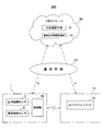
- FIG. 10 shows a conceptual diagram of an electronic key system 300 in which the biometric authentication means 8 and the registered biometric information storage unit 13 are provided in the cloud server 50.
- control unit 7 ⁇ / b> B of the portable device 1 detects that the portable device 1 is worn by the user by the attachment / detachment detection sensor 4, and then when the biological recognition sensor 2 detects the wearer's biological information, the cloud server 50.
- the biometric authentication unit 8 discriminates the coincidence with the biometric information of the registered user.
- the control unit 7B of the portable device 1 in order to transmit the wearer's biometric information detected by the biometric sensor 2 to the cloud server 50 via the communication line 51, the control unit 7B of the portable device 1 once transmits the biometric information to the control unit of the automobile 16.
- a method a for transferring from the control unit 7C to the cloud server 50 and a method b for the portable device 1 to directly access the cloud server 50 for transmission.
- the portable device 1 in the case of the latter method b is preferably a wireless terminal portable device such as a smartphone or a tablet computer that can be connected to the cloud server 50 via the communication line 51.
- the electronic key system 300 similarly to the electronic key systems 100 and 200, the electronic key system 300 also includes the biometric recognition sensor 2 and the attachment / detachment detection sensor 4 in the portable device 1. Then, the control unit 7C of the automobile 16 intermittently transmits a request signal for requesting the transmission of the ID to the portable device 1 from the wireless communication device 14, but the portable device 1 responds to the reception of the request signal by receiving the ID. Has the same functions as those of the electronic key systems 100 and 200.
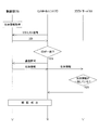
- FIG. 11 is a sequence diagram for explaining the process until the authentication between the control unit 7B and the control unit 7C of the portable device 1 is established in the case of the method a for transferring the biological information transmitted from the portable device 1 to the cloud server 50. It is.
- the control unit 7B transmits the ID by receiving the request signal transmitted from the control unit 7C.
- the control unit 7C transmits the acquired biological information to the control unit 7C by permitting communication when the transmitted ID matches the ID stored in advance.
- the control unit 7C transfers the biometric information to the cloud server 50, and the cloud server 50 determines whether the biometric information matches the biometric information stored in the registered biometric information storage unit 13. Thereby, authentication between control unit 7C and control part 7B is materialized.
- FIG. 12 is a sequence diagram for explaining until authentication between the control unit 7B and the control unit 7C of the portable device 1 is established in the method b in which the biological information acquired by the portable device 1 is directly transmitted to the cloud server 50. It is.
- the control unit 7 ⁇ / b> B transmits the biological information to the cloud server 50 when the biological recognition sensor 2 acquires the biological information.
- the cloud server 50 determines whether or not the biometric information matches the biometric information stored in the registered biometric information storage unit 13. If the biometric information matches, the cloud server 50 transmits a match signal to the control unit 7B. Then, after inputting the coincidence signal, the control unit 7B transmits the ID by receiving the request signal transmitted from the control unit 7C.
- the control unit 7C permits authentication between the control unit 7C and the control unit 7B by permitting communication when the transmitted ID matches the ID stored in advance.
- the portable device 1 is worn as described in the electronic key system 100, although not shown.
- a command code for the automobile is transmitted to the control unit 7C by the movement of the user's part.
- the control unit 7C detects the movement of the hand of the user wearing the portable device 1, and controls the operation of the automobile according to this movement.
- the biometric information of the user registered in this way is stored in the cloud server 50, and biometric authentication is performed by the cloud server 50, whereby authentication is established with a plurality of vehicle control units using one portable device 1. It becomes possible. Therefore, in the owner of a plurality of cars, a rental car shop, etc., the troublesomeness of managing the portable device 1 for each car is eliminated.
- the cloud server 50 also has user-specific driving propensity information (calibration), such as seat position, home or work address, frequently visited places, shops, driving styles, and sleep time. -By storing information such as the distance between the preceding vehicle according to the speed and the timing for applying the brake according to the distance between the vehicles, especially in the case of a car that performs automatic driving, this information is downloaded. Thus, it is possible to automatically provide the driving state and the movement to the destination according to the user's preference.
- calibration user-specific driving propensity information
- autonomous driving is an automatic driving system that has been researched and developed in recent years to further improve road traffic safety. This system recognizes the environment around the vehicle. It runs automatically.
- the automated level of an automated driving system for vehicles such as automobiles is defined in four stages from level 1 to level 4.
- Level 1 is called a safe driving support system, where the vehicle performs acceleration, steering, or braking.
- Level 2 is called a semi-automatic driving system (semi-automatic driving), in which a vehicle performs a plurality of operations of acceleration, steering, and braking simultaneously.
- Level 3 is a state in which acceleration, steering, and braking are all performed by the vehicle and the driver responds only in an emergency. This is also called a semi-automatic driving system.
- Level 4 is called a fully automatic driving system in which acceleration, steering and braking are all performed by a person other than the driver and the driver is not involved at all.
- Levels 2 to 4 are also called automated driving systems ("Step SIP (Strategic Innovation Creation Program) Automated Driving System Research and Development Plan", November 13, 2014, Cabinet Office, Policy Director (Science Technology and innovation)). Therefore, “automatic driving” includes all automatic driving of the fully automated level from level 1 to level 4.
- the present invention is not limited to the above-described embodiments, and various modifications or changes are made within the technical scope thereof.
- the user wearing the portable device 1 is not limited to a bracelet, but may be a ring, a headband, a necklace, a pendant, or the like.
- the user's movement is not limited to the arm or palm, but may be the movement of the head.
Landscapes
- Engineering & Computer Science (AREA)
- Health & Medical Sciences (AREA)
- Life Sciences & Earth Sciences (AREA)
- Mechanical Engineering (AREA)
- Physics & Mathematics (AREA)
- Computer Security & Cryptography (AREA)
- Theoretical Computer Science (AREA)
- Human Computer Interaction (AREA)
- General Health & Medical Sciences (AREA)
- Animal Behavior & Ethology (AREA)
- Biophysics (AREA)
- Pathology (AREA)
- Biomedical Technology (AREA)
- Heart & Thoracic Surgery (AREA)
- Medical Informatics (AREA)
- Molecular Biology (AREA)
- Surgery (AREA)
- Veterinary Medicine (AREA)
- Public Health (AREA)
- General Engineering & Computer Science (AREA)
- General Physics & Mathematics (AREA)
- Software Systems (AREA)
- Computer Hardware Design (AREA)
- Lock And Its Accessories (AREA)
- Image Input (AREA)
- Measurement Of The Respiration, Hearing Ability, Form, And Blood Characteristics Of Living Organisms (AREA)
Abstract
Provided is an electronic key system that enables an instruction to be given, to an automobile, from a portable machine side where biometric authentication of a user has been obtained. A portable machine (1) to be worn by the user determines, when biometric information of a wearer is detected by a biometric recognition sensor (2), whether or not biometric information detected by a biometric authentication means (8) matches biometric information of the user registered in advance. Then, when the biometric authentication means (8) verifies that the wearer is a registered user, the portable machine (1) enables, by a communication control means (9), near-field radio communication with a control unit (15) mounted in an automobile (16) by a radio communication apparatus (6). Thus, the portable machine (1) can instruct an operation to the automobile (16) through radio communication with the control unit (15).
Description
本発明は、電子キーシステムに関し、特に権限を有するユーザが自動車に動作の指示を与えることができる電子キーシステムに関する。
The present invention relates to an electronic key system, and more particularly to an electronic key system that allows an authorized user to give an operation instruction to a vehicle.
近年、キーを差し込まずに自動車のドアロックの開閉やエンジンの始動・停止等ができる電子キーシステムが開発されている。
In recent years, electronic key systems have been developed that can open and close automobile door locks and start / stop engines without inserting a key.
このような電子キーシステムにおいて、セキュリティーを確保するために、登録者の生体情報を登録データとして記憶する着脱式のデータ記憶手段を車体内にセットしておき、自動車への搭乗者から採取した生体情報が登録データと一致するとドアロックの開閉や運転を可能とする生体認証によるキーシステムが開示されている(例えば、特許文献1を参照)。
In such an electronic key system, in order to ensure security, detachable data storage means for storing biometric information of a registrant as registration data is set in the vehicle body, and a biometric sample collected from a passenger in a car A key system based on biometric authentication that enables opening / closing and operation of a door lock when the information matches registered data is disclosed (see, for example, Patent Document 1).
しかしながら、特許文献1による従来技術は、ユーザがドアのアウタハンドルを手で掴んだとき、アウタハンドルに設けられている第1生体センサから採取された生体情報が登録情報と一致するとドアロックを開放し、インストルメントパネルに設けられている第2生体センサから採取された生体情報が登録情報と一致すると自動車の運転を可能とするものである。したがって、自動車に指示する項目に応じて生体センサを設けなければならずコストが嵩む問題があった。
However, in the conventional technique disclosed in Patent Document 1, when the user grips the outer handle of the door by hand, the door lock is released when the biometric information collected from the first biosensor provided on the outer handle matches the registered information. When the biological information collected from the second biological sensor provided on the instrument panel matches the registered information, the vehicle can be driven. Therefore, there has been a problem that the biosensor must be provided in accordance with the items instructed to the automobile, which increases the cost.
本発明は、上記点に鑑みて、ユーザの生体認証が取れた携帯機側から自動車への指示を行うことを可能とする電子キーシステムを提供する。
In view of the above points, the present invention provides an electronic key system that makes it possible to give instructions to a vehicle from a portable device that has been authenticated by a user.
本発明の電子キーシステムは、ユーザが身体に着用することで携帯される携帯機によって自動車に搭載のコントロールユニットに動作を指示する電子キーシステムであって、予め登録されたユーザの生体情報を格納している登録生体情報記憶手段と、前記ユーザの前記生体情報が予め登録された前記ユーザの生体情報と一致するか否かを判別する生体認証手段と、を備えて、前記携帯機は、少なくとも前記ユーザの生体情報を検知する生体認識センサを含み、前記生体認証手段によって前記ユーザが登録ユーザであることが確証されたとき、前記携帯機と前記コントロールユニットとの間の認証が成立することを特徴としている。
The electronic key system of the present invention is an electronic key system that instructs a control unit mounted on an automobile to operate by a portable device that is carried when the user wears it on the body, and stores biometric information of the user registered in advance. Registered biometric information storage means, and biometric authentication means for determining whether or not the biometric information of the user matches preregistered biometric information of the user, and the portable device includes at least Including a biometric sensor for detecting biometric information of the user, and when the biometric authentication unit confirms that the user is a registered user, authentication between the portable device and the control unit is established. It is a feature.
このとき、前記携帯機は、着脱検知手段を備えて、前記生体認証手段は、前記着脱検知手段が着用を検出したとき、前記生体情報の一致の判別を行い、一致していると前記携帯機と前記コントロールユニットとの間の認証を成立させる。そして、前記生体認証手段は、認証の成立後、前記ユーザが前記携帯機の取り外したことを前記着脱検知手段が検出したとき、前記認証を解除するようにするとよい。これにより、携帯機の着用者だけが自動車に指示を与えることができる。
At this time, the portable device includes an attachment / detachment detection unit, and the biometric authentication unit determines whether the biometric information matches when the attachment / detachment detection unit detects wearing, and the portable device indicates that they match. And authentication between the control unit and the control unit. The biometric authentication unit may cancel the authentication when the attachment / detachment detection unit detects that the user has detached the portable device after the authentication is established. Thereby, only the wearer of a portable machine can give directions to a car.
さらに、前記携帯機は、前記ユーザが当該携帯機を着用した部位の動きを検知する運動検出手段と、前記運動検出手段が前記部位の特定の動きを検出すると、この動きに応じた前記自動車への命令コードを生成して、前記無線通信装置から送信するよう制御する動作指示手段と、を備えるとよい。これにより、ユーザは、携帯機を着用した身体の部位の動きで自動車に指示を与えることができる。
Further, the portable device detects movement of a part where the user wears the portable machine, and when the movement detection means detects a specific movement of the part, the portable device moves to the automobile corresponding to the movement. It is good to provide the operation instruction | indication means to control to generate | occur | produce and transmit this instruction code from the said radio | wireless communication apparatus. Thereby, the user can give an instruction | indication to a motor vehicle by the motion of the body part which wore the portable machine.
また、前記コントロールユニットは、前記生体認証手段によって前記着用者が登録ユーザであることが確証された前記携帯機を認識する携帯機認識手段と、前記ユーザの動きを撮像する撮像装置と、前記撮像部からの撮像情報に基づき前記ユーザの特定の動きを検出する画像認識手段と、検出した前記特定の動きに応じて、自動車の動作を制御する動作制御手段と、を備えてもよい。この場合には、権限を有する登録されたユーザの動きを画像認識処理することで自動車に指示を与えることができる。
In addition, the control unit includes a portable device recognition unit that recognizes the portable device in which the wearer is confirmed to be a registered user by the biometric authentication unit, an imaging device that images the movement of the user, and the imaging An image recognition unit that detects a specific movement of the user based on imaging information from a unit, and an operation control unit that controls the operation of the automobile according to the detected specific movement. In this case, an instruction can be given to the automobile by performing image recognition processing of the movement of the registered user having authority.
また、前記生体情報記憶手段と前記生体認証手段とをそれぞれクラウドサーバに設けてもよい。この場合、前記コントロールユニットは、前記携帯機から送信される前記生体情報を前記クラウドサーバに転送することで、前記生体認証手段の判別結果に基づいて、前記携帯機との間の認証を成立させることができる。
Further, the biometric information storage means and the biometric authentication means may each be provided in a cloud server. In this case, the control unit establishes authentication with the portable device based on the determination result of the biometric authentication unit by transferring the biological information transmitted from the portable device to the cloud server. be able to.
一方、前記携帯機が、前記生体情報を前記クラウドサーバに送信し、前記生体認証手段の判別結果に基づいて、前記コントロールユニットとの間の認証を成立させることもできる。このようなクラウドサーバを用いることで、一つの携帯機で複数の自動車のコントロールユニットとの間で認証を成立させることが可能となる。
On the other hand, the portable device can transmit the biometric information to the cloud server, and can establish authentication with the control unit based on the determination result of the biometric authentication means. By using such a cloud server, it is possible to establish authentication with the control units of a plurality of automobiles with a single portable device.
さらに、前記生体情報記憶手段には、記憶している生体情報に対応する前記ユーザの自動車の運転に関する性向情報を併せて記憶させておけば、前記コントロールユニットは、前記携帯機との間の認証が成立したとき、前記性向情報をダウンロードすることが可能となる。これにより、コントロールユニットは、当該ユーザの性向に応じて、自動車の動作を制御することができる。
Further, if the biometric information storage means stores propensity information related to the driving of the user's automobile corresponding to the stored biometric information, the control unit can authenticate with the portable device. When is established, the propensity information can be downloaded. Thereby, the control unit can control operation | movement of a motor vehicle according to the said user's tendency.
本発明の電子キーシステムによれば、ユーザの生体情報の取得を携帯機側で行うことで、自動車内には指示する項目に応じて複数の生体認識センサを設けずとも済み、簡略化された生体認証による電子キーシステムが提供される。
According to the electronic key system of the present invention, by obtaining the user's biometric information on the portable device side, there is no need to provide a plurality of biometric recognition sensors in the car according to the instructed item, which is simplified. An electronic key system based on biometric authentication is provided.
以下、本発明に係る電子キーシステムの実施の形態を図面に基づき説明する。
Embodiments of an electronic key system according to the present invention will be described below with reference to the drawings.
図1は、電子キーシステム100の構成全体を概念的にブロック図で示している。電子キーシステム100は、ワイヤレスにより自動車16に動作を指示するシステムであって、ユーザによって携帯される携帯機1と、自動車16に搭載されたコントロールユニット15とからなる。
FIG. 1 conceptually shows the entire configuration of the electronic key system 100 in a block diagram. The electronic key system 100 is a system for instructing an operation to the automobile 16 by wireless, and includes a portable device 1 carried by a user and a control unit 15 mounted on the automobile 16.
携帯機1は、図2及び図3に示すようにユーザが腕に着用することができるようにブレスレット20に装着されている。携帯機1は、生体認識センサ2と、運動検知センサ3と、ブレスレット20のユーザへの着脱を検知する着脱検知センサ4と、登録指示装置5と、無線通信装置6と、制御部7とから構成される。
The portable device 1 is attached to the bracelet 20 so that the user can wear it on the arm as shown in FIGS. The portable device 1 includes a biological recognition sensor 2, a motion detection sensor 3, an attachment / detachment detection sensor 4 that detects attachment / detachment of the bracelet 20 to a user, a registration instruction device 5, a wireless communication device 6, and a control unit 7. Composed.
生体認識センサ2は、指紋、指の静脈パターン、心臓の鼓動等のユーザの生体情報を検知する。本例での生体認識センサ2は指紋センサであり、人の指23の先端の指紋部分が携帯機1の表面に押しつけられると、その指紋を生体情報として検出する。
The biometric sensor 2 detects user biometric information such as fingerprints, finger vein patterns, and heartbeats. The biometric recognition sensor 2 in this example is a fingerprint sensor. When the fingerprint portion at the tip of a human finger 23 is pressed against the surface of the portable device 1, the fingerprint is detected as biometric information.
運動検知センサ3は、携帯機1を着用したユーザの腕の動きによる携帯機1の移動量及び移動角度を検知する。このような運動検知センサ3には、加速度センサや角速度センサ又はその両方が使用されるが、本例では、加速度センサと角速度センサの両方を用いて、3軸での移動量や角速度を検出する。
The movement detection sensor 3 detects the movement amount and movement angle of the portable device 1 due to the movement of the arm of the user wearing the portable device 1. As such a motion detection sensor 3, an acceleration sensor and / or an angular velocity sensor are used. In this example, both the acceleration sensor and the angular velocity sensor are used to detect a movement amount and an angular velocity in three axes. .
着脱検知センサ4は、ブレスレット20がユーザの腕に着用されて、その両端がバックル22で結合されると装着信号、結合が解除されると装着解除信号をそれぞれ出力する。
The attachment / detachment detection sensor 4 outputs a mounting signal when the bracelet 20 is worn on the user's arm and both ends thereof are coupled by the buckle 22, and a mounting release signal when the coupling is released.
無線通信装置6は、RF帯で自動車16のコントロールユニット15と近距離で無線通信する。この場合、コントロールユニット15が無線通信範囲内に存在する携帯機1が予め登録されたものであることを判別したとき、無線通信が可能となる。
The wireless communication device 6 wirelessly communicates with the control unit 15 of the automobile 16 at a short distance in the RF band. In this case, when the control unit 15 determines that the portable device 1 existing in the wireless communication range is registered in advance, wireless communication is possible.
制御部7は、CPU、ROM、RAMを含むコンピュータで構成されており、生体認証手段8、通信制御手段9、運動検出手段10、動作指示手段11及び生体情報登録手段12のそれぞれは、CPUがROMに格納されている制御プログラムを処理することで実現される。そして、制御部7は、登録生体情報を記憶しているフラッシュメモリによる登録生体情報記憶部13を備えている。
The control unit 7 includes a computer including a CPU, a ROM, and a RAM. Each of the biometric authentication unit 8, the communication control unit 9, the motion detection unit 10, the operation instruction unit 11, and the biometric information registration unit 12 is performed by the CPU. This is realized by processing a control program stored in the ROM. And the control part 7 is provided with the registration biometric information storage part 13 by the flash memory which has memorize | stored registration biometric information.
生体情報登録手段12は、登録指示装置5からの登録指示信号に応答して、生体認識センサ2が検知している生体情報(本例では指紋情報)をフラッシュメモリによる登録生体情報記憶部13に格納する。この場合、登録生体情報記憶部13には複数の生体情報を登録することができる。登録指示装置5は、登録者による所定の操作により、登録指示信号を出力するスイッチ装置によって構成されるが、セキュリティーの面から、登録指示装置5は、通常、携帯機1とは別体で設けて、登録設定時に携帯機1に接続して使用するように構成するのが好ましい。
In response to the registration instruction signal from the registration instruction device 5, the biometric information registration unit 12 stores the biometric information (in this example, fingerprint information) detected by the biometric recognition sensor 2 in the registered biometric information storage unit 13 using a flash memory. Store. In this case, a plurality of pieces of biological information can be registered in the registered biological information storage unit 13. The registration instruction device 5 is configured by a switch device that outputs a registration instruction signal by a predetermined operation by a registrant. However, the registration instruction device 5 is usually provided separately from the portable device 1 from the viewpoint of security. Therefore, it is preferable that the mobile phone 1 is used by being connected at the time of registration setting.
生体認証手段8は、ブレスレット20がユーザの腕に着用されたとき、生体認識センサ2が生体情報を検知すると、検知された生体情報と登録生体情報記憶部13に記憶されている登録生体情報とを比較して、互いに一致しているか否かを判別する。そして、一致しているときには、前記RAMに設けている認証フラグ8aをセットする。
When the biometric recognition sensor 2 detects biometric information when the bracelet 20 is worn on the user's arm, the biometric authentication unit 8 detects the detected biometric information and the registered biometric information stored in the registered biometric information storage unit 13. Are compared to determine whether or not they match each other. If they match, the authentication flag 8a provided in the RAM is set.
通信制御手段9は、携帯機1と自動車16のコントロールユニット15との間で機器間認証のための信号の授受を行う。
The communication control means 9 exchanges signals for inter-device authentication between the portable device 1 and the control unit 15 of the automobile 16.
運動検出手段10は、運動検知センサ3がユーザの腕の動きに伴う携帯機1の移動量及び移動角度を検知すると、これら検知情報から携帯機1の移動位置を算出する。続いて、運動検出手段10は、その直後のユーザによる再度の腕の動きによって、運動検知センサ3が携帯機1の移動量及び移動角度を検知したとき、その検知情報から算出した移動位置が携帯機1の原の位置であるときには、ユーザは腕を往復移動させたと判定する。図3は、着用者23が肘を支点にして腕を矢印方向aに上下に回動させたときの状態を模式的に示している。
When the movement detection sensor 3 detects the movement amount and movement angle of the portable device 1 accompanying the movement of the user's arm, the movement detection means 10 calculates the movement position of the portable device 1 from these detection information. Subsequently, when the movement detection sensor 3 detects the movement amount and movement angle of the portable device 1 due to the movement of the arm again by the user immediately after that, the movement position calculated from the detection information is portable. When it is the original position of the machine 1, the user determines that the arm has been reciprocated. FIG. 3 schematically shows a state when the wearer 23 rotates the arm up and down in the arrow direction a with the elbow as a fulcrum.
動作指示手段11は、運動検出手段10が検出した往復運動に応じて、予め設定されている自動車16に与える指示の内容を判別し、その指示を示す命令コードを生成して、無線通信装置6から自動車16のコントロールユニット15に送信する。前記ROMには、運動検出手段10が検出する往復運動の種類とその往復運動が意味する自動車16への指示内容とを対照させた動作指示テーブル11bが設定されている。例えば、動作指示テーブル11bには、図4に示すように、携帯機1の上下及び左右の各往復回転運動と、平行移動による上下及び左右の各往復運動について、その運動によって自動車16に指示する指示内容が設定されている。
The operation instructing means 11 discriminates the content of an instruction given to the automobile 16 set in advance according to the reciprocating motion detected by the motion detecting means 10, generates a command code indicating the instruction, and generates a command code. To the control unit 15 of the automobile 16. In the ROM, an operation instruction table 11b is set in which the type of reciprocating motion detected by the motion detecting means 10 is compared with the instruction content to the automobile 16 that means the reciprocating motion. For example, as shown in FIG. 4, the movement instruction table 11 b instructs the automobile 16 about the vertical and horizontal reciprocating motions of the portable device 1 and the vertical and horizontal reciprocating motions of the parallel movement. Instruction contents are set.
したがって、動作指示手段11は、図3で示すように、着用者23が肘を支点とした携帯機1の上下往復回転運動を行うと、ドアロックの解除を自動車16に指示する内容であることを動作指示テーブル11bから読み取って、この動作を指示する命令コードをコントロールユニット15に送信する。
Therefore, as shown in FIG. 3, when the wearer 23 performs a reciprocating rotary motion of the portable device 1 with the elbow as a fulcrum, the operation instruction means 11 is a content that instructs the automobile 16 to release the door lock. Is read from the operation instruction table 11 b and an instruction code for instructing this operation is transmitted to the control unit 15.
コントロールユニット15は、CPUからなる自動車16の主制御部であり、自動車16に搭載される電子機器の制御処理を予め定められたソフトウェアの実行に基づいて実施する。図1では、本発明に係る電子キーシステム100の動作と直接関係する携帯機認識手段24のみを示しているが、この機能もこのソフトウェアを実行することで実現される。
The control unit 15 is a main control unit of the automobile 16 composed of a CPU, and performs control processing of electronic devices mounted on the automobile 16 based on execution of predetermined software. In FIG. 1, only the portable device recognition means 24 directly related to the operation of the electronic key system 100 according to the present invention is shown, but this function is also realized by executing this software.
携帯機認識手段24は、携帯機1へIDの送信を要求するリクエスト信号を無線通信装置14から間欠的に発信させる。そして、リクエスト信号の範囲内に入った携帯機1が無線通信装置6でリクエスト信号を受信し、これに応答してIDを発信すると、携帯機認識手段24は、予め設定されているIDと比較し、一致していると当該携帯機1の存在を認識する。
The portable device recognition means 24 intermittently transmits a request signal for requesting the portable device 1 to transmit an ID from the wireless communication device 14. Then, when the portable device 1 that falls within the range of the request signal receives the request signal by the wireless communication device 6 and sends an ID in response thereto, the portable device recognition means 24 compares it with the preset ID. If they match, the presence of the portable device 1 is recognized.
そして、コントロールユニット15は、無線通信装置14を介して存在を認識した携帯機1からの命令コードが入力されると、その命令コードの内容に応じて、自動車16に搭載されたドアロック駆動装置17、エンジン駆動装置18、ステアリングロック駆動装置19等を駆動させる。
When the command code from the portable device 1 whose presence has been recognized is input via the wireless communication device 14, the control unit 15 receives a door lock driving device mounted on the automobile 16 according to the content of the command code. 17, the engine drive device 18, the steering lock drive device 19 and the like are driven.
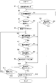
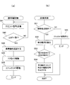
上記構成による電子キーシステム100の動作を図5のフローチャートに基づき説明する。
The operation of the electronic key system 100 configured as described above will be described with reference to the flowchart of FIG.
携帯機1は、ブレスレット20がユーザの腕に巻かれて着用され、バックル22が係止されると、制御部7には着脱検知センサ4からの装着信号が入力されて動作を開始する(ステップS1)。
When the bracelet 20 is wound around the user's arm and worn, and the buckle 22 is locked, the portable device 1 is operated by receiving an attachment signal from the attachment / detachment detection sensor 4 (step 7). S1).
そして、制御部7は、生体認証手段8によって、生体認識センサ2で生体情報が検出されたかを判別する(ステップS2)。携帯機1の着用後、着用者23が携帯機1のパッケージの表面に指先を載せると、生体認識センサ2は指紋による生体情報を出力するが、生体認識センサ2が生体情報を出力するまでの間に、着脱検知センサ4から装着解除信号が入力されると(ステップS3の「YES」)、制御部7は動作を終了する。これは、携帯機1はユーザに着用されたものの、携帯機1のパッケージ表面に指先を載せることなく携帯機1を腕から取り外した場合の動作である。
And the control part 7 discriminate | determines whether biometric information was detected by the biometric recognition sensor 2 by the biometrics authentication means 8 (step S2). When the wearer 23 puts a fingertip on the surface of the package of the portable device 1 after the portable device 1 is worn, the biological recognition sensor 2 outputs biological information based on the fingerprint, but until the biological recognition sensor 2 outputs the biological information. In the meantime, when a mounting release signal is input from the attachment / detachment detection sensor 4 (“YES” in step S3), the control unit 7 ends the operation. This is an operation when the portable device 1 is worn by the user, but the portable device 1 is removed from the arm without placing a fingertip on the package surface of the portable device 1.
着用者23がパッケージ表面に指先を載せたときには、生体認証手段8は、生体認識センサ2が検出した生体情報と登録生体情報記憶部13に記憶されている登録生体情報とを照合して、着用者23が予め登録されたユーザであるか否かを判定する(ステップS4)。そして、照合が一致せず登録ユーザでない「NO」の場合には、後に説明するステップS10の処理となる。
When the wearer 23 places his fingertip on the package surface, the biometric authentication unit 8 collates the biometric information detected by the biometric recognition sensor 2 with the registered biometric information stored in the registered biometric information storage unit 13 and wears it. It is determined whether or not the person 23 is a previously registered user (step S4). If the collation does not match and the user is not a registered user, the process is step S10 described later.
生体認証手段8は、生体情報の一致によって着用者23が登録ユーザであることを確証すると(ステップS4の「YES」)、着用者23が登録ユーザであることを示す認証フラグ8aをセットする(ステップS5)。
When the biometric authentication unit 8 confirms that the wearer 23 is a registered user by matching the biometric information (“YES” in step S4), the biometric authentication unit 8 sets an authentication flag 8a indicating that the wearer 23 is a registered user ( Step S5).
そして、制御部7は、通信制御手段9によって、周囲に存在している自動車16のコントロールユニット15と無線通信接続されているか否かを判定する(ステップS6)。ここでの動作は、着用者23が自動車16に近づいたとき、通信制御手段9は、コントロールユニット15が携帯機認識手段24によって発信しているリクエスト信号を受信する。そして、通信制御手段9は、リクエスト信号を受信したとき、これに応答してIDを発信することで、携帯機認識手段24によって無線通信接続が確立される。これによって、制御部7とコントロールユニット15との間の認証が成立したことになる。
Then, the control unit 7 determines whether or not the communication control means 9 is wirelessly connected to the control unit 15 of the automobile 16 existing in the vicinity (step S6). In this operation, when the wearer 23 approaches the automobile 16, the communication control means 9 receives a request signal transmitted from the control unit 15 by the portable device recognition means 24. And when the communication control means 9 receives a request signal, ID is transmitted in response to this, and the portable communication recognition means 24 establishes a wireless communication connection. As a result, authentication between the control unit 7 and the control unit 15 is established.
携帯機認識手段24によって無線通信接続が確立されているときは(ステップS6の「YES」)、制御部7は、運動検出手段10によって、携帯機1が往復移動したか否かを判別する(ステップS7)。このとき運動検出手段10は、運動検知センサ3が出力する携帯機1の移動量及び移動角度から移動位置を算出したとき、次に運動検知センサ3が出力する携帯機1の移動量及び移動角度から算出する移動位置が移動前の元の位置である場合に、往復移動されたと判断する。このとき、運動検出手段10は、運動検出手段10が検知した移動量及び移動角度からその往復運動の内容を判定する。移動角度に変化があれば回転運動であり、変化が無ければ平行運動となる。
When the wireless communication connection is established by the portable device recognition means 24 (“YES” in step S6), the control unit 7 determines whether or not the portable device 1 has reciprocated by the motion detection means 10 ( Step S7). At this time, when the movement detection means 10 calculates the movement position from the movement amount and movement angle of the portable device 1 output from the movement detection sensor 3, the movement amount and movement angle of the portable device 1 output from the movement detection sensor 3 next. When the movement position calculated from the above is the original position before the movement, it is determined that the movement is reciprocated. At this time, the motion detection means 10 determines the content of the reciprocating motion from the movement amount and the movement angle detected by the motion detection means 10. If there is a change in the movement angle, it is a rotational movement, and if there is no change, it becomes a parallel movement.
携帯機1が往復移動したとき、制御部7は、動作指示手段11によって、運動検出手段10が判定した往復運動の内容に基づき動作指示テーブル11bを参照して、この動きが自動車16に動作への指示内容を示す動きであるか否かを判別する(ステップS8)。そして、動作指示手段11は、指示内容を示す動きであることを判別すると、この指示を示す命令コードを自動車16のコントロールユニット15に出力する(ステップS9)。
When the portable device 1 reciprocates, the control unit 7 refers to the operation instruction table 11b based on the contents of the reciprocating motion determined by the motion detecting unit 10 by the operation instructing unit 11, and this movement is activated in the automobile 16. It is determined whether or not the movement indicates the instruction content (step S8). Then, when it is determined that the movement indicates the instruction content, the operation instruction means 11 outputs an instruction code indicating this instruction to the control unit 15 of the automobile 16 (step S9).
図3に示す例では、着用者23が携帯機1を着用している腕の肘を支点にして上方向に回動させる矢印aに示す動きを行っており、動作指示手段11は、自動車16のドアロックを解除の指示であることを判別して、コントロールユニット15にドアロック解除の命令コードを送信する。したがって、命令コードを受信したコントロールユニット15は、ドアロック駆動装置17に駆動信号を出力してドアロックを解除する。
In the example shown in FIG. 3, the wearer 23 performs the movement indicated by the arrow a that rotates upward with the elbow of the arm wearing the portable device 1 as a fulcrum. The door lock release instruction code is transmitted to the control unit 15. Therefore, the control unit 15 that has received the instruction code outputs a drive signal to the door lock driving device 17 to release the door lock.
逆に、携帯機1を下方向に回動させる動きを行うと、動作制御手段は、自動車16のドアロック指示であることを判別して、コントロールユニット15にドアロックの命令コードを送信する。また、本例の動作指示テーブル11bでは、ユーザが携帯機1を着用している腕を平行に持ち上げると、エンジン始動を指示する動きとなり、動作指示手段11は、エンジン始動の命令コードを生成して自動車16のコントロールユニット15に出力する。
Conversely, when the mobile device 1 is rotated downward, the operation control means determines that it is a door lock instruction for the automobile 16 and transmits a door lock command code to the control unit 15. Further, in the operation instruction table 11b of this example, when the user lifts the arm wearing the portable device 1 in parallel, the movement is instructed to start the engine, and the operation instruction means 11 generates an instruction code for starting the engine. To the control unit 15 of the automobile 16.
制御部7は、動作指示手段11によって命令コードを送信すると、着脱検知センサ4から装着解除信号が出力されているかを判別する(ステップS10)。そして、装着解除信号が出力されていないと(ステップS10の「NO」)、制御部7は、認証フラグ8aがセットされていると(ステップS11の「NO」)、ステップS5乃至S11の処理を繰り返して、この間に、無線通信接続が可能な状態(ステップS6の「YES」)で、着用者23による指示内容を示す動きを検知した際には、それに応じた命令コードをコントロールユニット15に送信する。
The control unit 7 determines whether or not an attachment release signal is output from the attachment / detachment detection sensor 4 when the instruction code is transmitted by the operation instruction unit 11 (step S10). If the mounting release signal is not output (“NO” in step S10), the control unit 7 performs the processing in steps S5 to S11 when the authentication flag 8a is set (“NO” in step S11). In the meantime, when a movement indicating the instruction content by the wearer 23 is detected in a state where wireless communication connection is possible ("YES" in step S6), an instruction code corresponding to the movement is transmitted to the control unit 15. To do.
また、前述したステップS6、S7及びS8の各判定処理で「NO」を判定したときも同様であり、着用者23が携帯機1を腕から外さず、且つ認証フラグ8aがセットされている限り、ステップS6からステップS11までの処理を繰り返す。
The same applies when “NO” is determined in each determination process of steps S6, S7, and S8 described above, as long as the wearer 23 does not remove the portable device 1 from the arm and the authentication flag 8a is set. The processes from step S6 to step S11 are repeated.
しかし、着用者23が携帯機1を腕から外したことで着脱検知センサ4から装着解除信号が出力されると(ステップS10の「YES」)、制御部7は、認証フラグ8aをリセットして動作を終了する(ステップS12)。したがって、携帯機1とコントロールユニット15との間の認証が解除される。
However, when the wearer 23 removes the portable device 1 from his / her arm and outputs an attachment release signal from the attachment / detachment detection sensor 4 (“YES” in step S10), the control unit 7 resets the authentication flag 8a. The operation is terminated (step S12). Therefore, the authentication between the portable device 1 and the control unit 15 is released.
一方、前述のステップS4で「NO」の判定からステップS10の処理となり、このとき装着解除信号が入力されておらず、続けてステップS11の処理となったとき、この場合は認証フラグ8aが非セットであるため制御部7は動作を終了する。すなわち、携帯機1は、着用者23は登録されたユーザとは異なることから、着用されても動作することがない。
On the other hand, if “NO” is determined in step S4 described above, the process proceeds to step S10. At this time, when the mounting release signal is not input and the process proceeds to step S11, the authentication flag 8a is not set in this case. Since it is a set, the control part 7 complete | finishes operation | movement. That is, since the wearer 23 is different from the registered user, the portable device 1 does not operate even when worn.
上記の実施形態では、携帯機1側でユーザの特定の動きを検出して、この動きに応じた自動車16への命令コードを出力しているが、自動車16側でユーザの特定の動きを検出することもできる。
In the above embodiment, the user's specific movement is detected on the portable device 1 side, and the instruction code to the automobile 16 corresponding to this movement is output, but the user's specific movement is detected on the automobile 16 side. You can also
図6は、このような実施形態による電子キーシステム200の構成全体を概念的にブロック図で示している。以下、電子キーシステム200の動作を説明するが、電子キーシステム100と共通する構成については、同一の符号を付して詳しい説明を省略する。
FIG. 6 conceptually shows a block diagram of the entire configuration of the electronic key system 200 according to such an embodiment. Hereinafter, the operation of the electronic key system 200 will be described. The components common to the electronic key system 100 are denoted by the same reference numerals, and detailed description thereof will be omitted.
電子キーシステム200では、自動車16のステアリングハンドル付近でのユーザの手の動きを撮像可能な位置、例えば車内の天井部分に撮像装置を配置している。撮像装置としては、ステレオカメラ25を用いて手の動きを撮影することにより、撮影される手の形状や距離、位置を三次元で認識することで手の動きを正確に捉えることができる。
In the electronic key system 200, an imaging device is disposed at a position where the movement of the user's hand in the vicinity of the steering handle of the automobile 16 can be imaged, for example, a ceiling portion in the vehicle. As an imaging apparatus, by capturing the movement of the hand using the stereo camera 25, the movement of the hand can be accurately captured by recognizing the shape, distance, and position of the captured hand in three dimensions.
コントロールユニット15Aは、CPUからなる自動車16の主制御部であり、自動車16に搭載される電子機器の制御処理を予め定められたソフトウェアの実行に基づいて実施する。図6においては、電子キーシステム200の動作と直接関係する、携帯機認識手段24、画像認識手段32、動作制御手段33のみを示しているが、これら各機能はこのソフトウェアを実行することで実現される。
The control unit 15A is a main control unit of the automobile 16 composed of a CPU, and performs control processing of electronic equipment mounted on the automobile 16 based on execution of predetermined software. FIG. 6 shows only the portable device recognition unit 24, the image recognition unit 32, and the operation control unit 33, which are directly related to the operation of the electronic key system 200, but these functions are realized by executing this software. Is done.
ここでの携帯機認識手段24も、電子キーシステム100で前述したのと同様に、携帯機1へIDの送信を要求するリクエスト信号を無線通信装置14から間欠的に発信し、リクエスト信号の範囲内に入った携帯機1が無線通信装置6でリクエスト信号を受信したとき、これに応答して発信してきたIDを予め設定されているIDと比較して、一致していると無線通信接続を確立する。
Here, the portable device recognition means 24 also intermittently transmits a request signal for requesting transmission of an ID to the portable device 1 from the wireless communication device 14 in the same manner as described above for the electronic key system 100, and the range of the request signal. When the portable device 1 that has entered the mobile communication device 6 receives a request signal, the ID transmitted in response to the request signal is compared with a preset ID, and if they match, the wireless communication connection is established. Establish.
画像認識手段32は、携帯機認識手段24が携帯機1を認識している間、ステレオカメラ25を動作させる。そして、ステレオカメラ25が捉えて出力する手の動きの三次元画像情報の画像認識処理を行ってユーザの手の動きを検出する。この処理には、ステレオカメラ25が捉えて出力する手の動きの三次元画像情報を画像処理して、予め設定されている標準パターンを用いて2値化処理した後、標準パターンを用いて2値化画像のパターンマッチングを行うことで手の動きを認識する周知の手法が用いられる。
The image recognition unit 32 operates the stereo camera 25 while the portable device recognition unit 24 recognizes the portable device 1. Then, image recognition processing is performed on the three-dimensional image information of the hand movement captured and output by the stereo camera 25 to detect the user's hand movement. In this process, three-dimensional image information of hand movements captured and output by the stereo camera 25 is subjected to image processing, binarized using a preset standard pattern, and then processed using a standard pattern. A well-known method for recognizing hand movement by performing pattern matching of a digitized image is used.
動作制御手段33は、画像認識手段32が判別したユーザの手の動きに応じて、ドアロック駆動装置17、エンジン駆動装置18、ステアリングロック駆動装置19、空調装置26、オーディオ装置27等の動作を制御する。
The operation control means 33 operates the door lock drive device 17, the engine drive device 18, the steering lock drive device 19, the air conditioner 26, the audio device 27, etc. according to the movement of the user's hand determined by the image recognition means 32. Control.
例えば、画像認識手段32が、ステアリングハンドル40の位置で左の手の平41を左右に振る図7に示すような動作を検出したとき、動作制御手段33は、エンジン駆動装置18に駆動信号を出力する。このように、ステアリングハンドルを操作するときに通常では行われない手の平の動きについて、その動きとそれに対応する自動車16の各部への指示内容が予めメモリ34に設定されている。このような動作としては、手の平を左右に振る以外にも、指を「グー」から「チョキ」や「パー」にする動作や親指を立てる動作などがある。
For example, when the image recognition unit 32 detects an operation as shown in FIG. 7 in which the left palm 41 is swung left and right at the position of the steering handle 40, the operation control unit 33 outputs a drive signal to the engine drive unit 18. . As described above, regarding the movement of the palm that is not normally performed when the steering wheel is operated, the movement and the corresponding instruction content to each part of the automobile 16 are set in the memory 34 in advance. In addition to shaking the palm to the left and right, such actions include moving the finger from “goo” to “choki” or “par”, and raising the thumb.
電子キーシステム200の動作を図8及び図9のフローチャートに基づき説明する。
The operation of the electronic key system 200 will be described with reference to the flowcharts of FIGS.
図8は携帯機1の動作を示すフローチャートで、携帯機1は、ブレスレット20がユーザの腕に巻かれて着用され、バックル22が係止されると、制御部7Aには着脱検知センサ4からの装着信号が入力されて動作を開始する(ステップS21)。
FIG. 8 is a flowchart showing the operation of the portable device 1. In the portable device 1, the bracelet 20 is wound around the user's arm and worn, and the buckle 22 is locked. Is input and the operation is started (step S21).
そして、制御部7Aは、生体認証手段8によって、生体認識センサ2で生体情報が検出されたかを判別する(ステップS22)。ここで、携帯機1の着用者23が携帯機1のパッケージの表面に指先を載せると、生体認識センサ2は指紋による生体情報を出力するが、生体認識センサ2が生体情報を出力するまでの間に、着脱検知センサ4から装着解除信号が入力されたとき(ステップS23の「YES」)、制御部7Aは、携帯機1はユーザによって着用されたものの、携帯機1のパッケージ表面に指先を載せることなく、携帯機1が腕から取り外されたと判断し、動作を終了する。
Then, the control unit 7A determines whether or not biometric information is detected by the biometric recognition sensor 2 by the biometric authentication unit 8 (step S22). Here, when the wearer 23 of the portable device 1 places a fingertip on the surface of the package of the portable device 1, the biometric recognition sensor 2 outputs biometric information based on the fingerprint, but the biometric recognition sensor 2 outputs biometric information. In the meantime, when an attachment release signal is input from the attachment / detachment detection sensor 4 (“YES” in step S23), the control unit 7A places the fingertip on the package surface of the portable device 1 although the portable device 1 is worn by the user. Without placing, it is determined that the portable device 1 has been removed from the arm, and the operation ends.
着用者23がパッケージ表面に指先を載せたときには、生体認証手段8は、生体認識センサ2が検出した生体情報と登録生体情報記憶部13に記憶されている登録生体情報とを照合して、着用者23が予め登録されたユーザであるか否かを判定する(ステップ24)。しかし、照合が一致せず登録ユーザでないときにはステップS27の処理となるが、このときの動作については後に明らかとなる。
When the wearer 23 places his fingertip on the package surface, the biometric authentication unit 8 collates the biometric information detected by the biometric recognition sensor 2 with the registered biometric information stored in the registered biometric information storage unit 13 and wears it. It is determined whether or not the person 23 is a previously registered user (step 24). However, when the collation does not match and the user is not a registered user, the processing of step S27 is performed, but the operation at this time will be clarified later.
生体認証手段8は、生体情報の一致によって着用者23が登録ユーザであることを確証すると(ステップS24の「YES」)、着用者23が登録ユーザであることを示す認証フラグ8aをセットする(ステップS25)。そして、制御部7Aは、認証フラグ8aがセット状態であるとき、自動車16のコントロールユニット15Aとの無線通信接続を可能な状態とする(ステップS26)。ここで、無線通信接続が可能な状態とは、自動車16のコントロールユニット15Aが携帯機認証手段24によってリクエスト信号を発信したとき、これに応答して携帯機1が通信制御手段9によってIDを送信することができる状態である。
When the biometric authentication unit 8 confirms that the wearer 23 is a registered user by matching the biometric information (“YES” in step S24), the biometric authentication unit 8 sets an authentication flag 8a indicating that the wearer 23 is a registered user ( Step S25). Then, when the authentication flag 8a is in the set state, the control unit 7A makes a wireless communication connection with the control unit 15A of the automobile 16 possible (step S26). Here, the state in which wireless communication connection is possible means that when the control unit 15A of the automobile 16 transmits a request signal by the portable device authentication means 24, the portable device 1 transmits an ID by the communication control means 9 in response thereto. It is a state that can be done.
そして、制御部7Aは、着脱検知センサ4から装着解除信号が入力されているか否かを判別し(ステップS27)、入力されていないときには、認証フラグ8aのセットを確認して(ステップS28)、フラグをセットしているときにはステップS26の処理に戻る。したがって、制御部7Aは、着脱検知センサ4から装着解除信号が入力されておらず、且つ認証フラグ8aがセット状態である間は、ステップS26において、コントロールユニット15Aとの無線通信を行うことが可能となっている。
Then, the control unit 7A determines whether or not a mounting release signal is input from the attachment / detachment detection sensor 4 (step S27), and if not input, checks the set of the authentication flag 8a (step S28). When the flag is set, the process returns to step S26. Therefore, the control unit 7A can perform wireless communication with the control unit 15A in step S26 while the attachment release signal is not input from the attachment / detachment detection sensor 4 and the authentication flag 8a is set. It has become.
しかし、着用者23が携帯機1を腕から外したことで、着脱検知センサ4から装着解除信号が出力されると(ステップS27の「YES」)、制御部7Aは、認証フラグ8aをリセットして動作を終了する(ステップS29)。したがって、認証フラグ8aをリセットすることで、無線通信が不能となる。
However, when the wearer 23 removes the portable device 1 from his / her arm, and the attachment release signal is output from the attachment / detachment detection sensor 4 (“YES” in step S27), the control unit 7A resets the authentication flag 8a. The operation is terminated (step S29). Therefore, wireless communication is disabled by resetting the authentication flag 8a.
ここで、ステップS24で生体情報の照合が一致せず、着用者が登録ユーザでないことを判別したときの制御部7Aの動作を説明する。この場合は認証フラグ8aがセットされず、またコントロールユニット15Aとの無線通信が不可の状態でステップS27の処理となる。そして、着脱検知センサ4から装着解除信号が出力されずに、次にステップS28の処理となると、認証フラグ8aが非セットであるため、制御部7Aは動作を終了することになる(ステップS28の「YES」)。したがって、権限を有さないユーザが携帯機1を着用していても、制御部7Aは、コントロールユニット15Aと無線通信を行うことがない。
Here, the operation of the control unit 7A when it is determined in step S24 that biometric information collation does not match and the wearer is not a registered user will be described. In this case, the authentication flag 8a is not set, and the process of step S27 is performed in a state where wireless communication with the control unit 15A is not possible. Then, when the attachment release signal is not output from the attachment / detachment detection sensor 4 and the next processing of step S28 is performed, since the authentication flag 8a is not set, the control unit 7A ends the operation (in step S28). "YES"). Therefore, even if a user without authority wears the portable device 1, the control unit 7A does not perform wireless communication with the control unit 15A.
携帯機1側での上記の動作に対しての、自動車16のコントロールユニット15Aの動作を図9のフローチャートで説明する。図9(a)は、コントロールユニット15Aの「携帯機認識」の動作を示すフローチャートである。コントロールユニット15Aは、携帯機認識手段24によって、携帯機1へIDを要求するリクエスト信号を発信している(ステップS41)。
The operation of the control unit 15A of the automobile 16 with respect to the above-described operation on the portable device 1 side will be described with reference to the flowchart of FIG. FIG. 9A is a flowchart showing the “portable device recognition” operation of the control unit 15A. The control unit 15A transmits a request signal for requesting an ID to the portable device 1 by the portable device recognition means 24 (step S41).
したがって、生体認証手段8により着用者が登録ユーザであることが確証された携帯機1がリクエスト信号の送信範囲内に入ったとき、制御部7Aは、ステップS26(図8)の処理を行うことで、予め設定されているIDを無線通信装置6から送信する。よって、携帯機認識手段24は、IDが送信されてくると、このIDが予め設定されているIDと一致しているかを判別し(ステップS42)、一致していると当該携帯機1の存在を認識する(ステップS43)。これによって、制御部7Aとコントロールユニット15Aとの間の認証が成立したことになる。
Therefore, when the portable device 1 whose wearer is confirmed to be a registered user by the biometric authentication unit 8 enters the transmission range of the request signal, the control unit 7A performs the process of step S26 (FIG. 8). Then, a preset ID is transmitted from the wireless communication device 6. Therefore, when the ID is transmitted, the portable device recognition means 24 determines whether or not this ID matches a preset ID (step S42). If the ID matches, the presence of the portable device 1 exists. Is recognized (step S43). As a result, authentication between the control unit 7A and the control unit 15A is established.
そして、コントロールユニット15Aは、ドアロック駆動装置17にドアロック解除信号を出力してドアロックを解除し(ステップS44)、ステレオカメラ25を駆動して携帯機認識処理のルーチンを終了する。
Then, the control unit 15A outputs a door lock release signal to the door lock drive device 17 to release the door lock (step S44), drives the stereo camera 25, and ends the routine of the portable device recognition process.
携帯機1の存在を認識した後、コントロールユニット15Aは、予め定められた自動車16に搭載される電子機器の制御処理を実行する一方で、タイマー割り込みにより、図9(b)のフローチャートに示す「画像認識」の処理を行う。
After recognizing the presence of the portable device 1, the control unit 15 </ b> A executes a control process for a predetermined electronic device mounted on the automobile 16, while a timer interrupt causes a “ The image recognition process is performed.
この割り込み処理では、先ずコントロールユニット15Aは、携帯機認識手段24によって携帯機1との通信接続が可能であるかを判別する(ステップS51)。この場合、携帯機認識手段24によるリクエスト信号の発信に応答して、携帯機1からIDが送信されてくるか否かで判断する。前述したように、携帯機1は認証フラグ8aをセットしていると無線通信接続が可能である。
In this interruption process, first, the control unit 15A determines whether the communication connection with the portable device 1 is possible by the portable device recognition means 24 (step S51). In this case, it is determined whether or not an ID is transmitted from the portable device 1 in response to the transmission of the request signal by the portable device recognition means 24. As described above, the portable device 1 can establish a wireless communication connection when the authentication flag 8a is set.
そして、携帯機1との通信が可能であるとき、コントロールユニット15Aは、画像認識手段32によってステレオカメラ25が捉えて出力する画像からユーザの手の動きを検出する(ステップS52)。そして、動作制御手段33は、検出した手の動きが自動車16の各部に対し動作を指示する内容であるかを判別し(ステップS53)、動作を指示する手の動きであるときには、その対象の構成部に駆動信号を出力した後、割り込み前の処理に戻る(ステップS54)。これにより、ユーザの指示通りに、例えば、空調装置26にはON・OFF信号や温度調節信号、オーディオ装置27には音量調整信号などが出力される。
When the communication with the portable device 1 is possible, the control unit 15A detects the movement of the user's hand from the image captured and output by the stereo camera 25 by the image recognition means 32 (step S52). Then, the motion control means 33 determines whether or not the detected hand movement is a content for instructing each part of the automobile 16 (step S53). After outputting the drive signal to the component, the process returns to the process before the interruption (step S54). Accordingly, for example, an ON / OFF signal or a temperature adjustment signal is output to the air conditioner 26, and a volume adjustment signal is output to the audio device 27 as instructed by the user.
しかし、ステップS51で、携帯機1との通信接続が不能と判定したときには、コントロールユニット15Aは、ステレオカメラ25の駆動を停止する(ステップS55)。そして、コントロールユニット15Aは、割り込み前の処理に戻るが、これ以後、「画像認識」の割り込み処理は行わない。これにより、コントロールユニット15Aが携帯機1を認識してドアロックを解除したとき、携帯機1を着用していない別人が車内に入って手を動かしても、自動車16に指示を与えることはできない。
However, if it is determined in step S51 that communication connection with the portable device 1 is impossible, the control unit 15A stops driving the stereo camera 25 (step S55). Then, the control unit 15A returns to the process before the interruption, but does not perform the “image recognition” interruption process thereafter. Thereby, when the control unit 15A recognizes the portable device 1 and releases the door lock, even if another person who does not wear the portable device 1 enters the vehicle and moves his hand, the vehicle 16 cannot be instructed. .
上記したように本発明に係わる電子キーシステム100、200は、ユーザが携帯機1を着用することで装着信号が発生した後に生体情報が入力されて、入力生体情報が予め登録された生体情報と一致している場合に、この着用者が予め登録された権限を有するユーザであることを確証する。そして、この確証後、電子キーシステム100では、ユーザは着用した腕の動きで自動車16に指示を与えることができる。そして、電子キーシステム200では、携帯機1の存在を認識すると、自動車16はドアロックを解除し、車内に搭乗したユーザが手の平で所定の動きをすることで、自動車16に指示を与えることができる。
As described above, the electronic key systems 100 and 200 according to the present invention include biometric information in which biometric information is input after a wearing signal is generated by the user wearing the portable device 1 and input biometric information is registered in advance. If they match, it is confirmed that the wearer is a user having authority registered in advance. After this confirmation, in the electronic key system 100, the user can give an instruction to the automobile 16 by the movement of the worn arm. In the electronic key system 200, when the presence of the portable device 1 is recognized, the automobile 16 releases the door lock, and the user who has boarded the vehicle can give an instruction to the automobile 16 by making a predetermined movement with the palm of the hand. it can.
また、上記した電子キーシステム100、200は携帯機1の制御部7、7Aに生体認証手段8及び登録生体情報記憶部13を設けているが、インターネット等の通信回線で接続されるクラウドに設けてもよい。
The electronic key systems 100 and 200 described above are provided with the biometric authentication unit 8 and the registered biometric information storage unit 13 in the control units 7 and 7A of the portable device 1, but are provided in a cloud connected via a communication line such as the Internet. May be.
図10は、クラウドサーバ50に生体認証手段8及び登録生体情報記憶部13を設けた電子キーシステム300の概念図を示している。
FIG. 10 shows a conceptual diagram of an electronic key system 300 in which the biometric authentication means 8 and the registered biometric information storage unit 13 are provided in the cloud server 50.
図10で携帯機1の制御部7Bは、着脱検知センサ4によって携帯機1がユーザに着用されるのを検知した後、生体認識センサ2が着用者の生体情報を検知したとき、クラウドサーバ50の生体認証手段8が、登録ユーザの生体情報との一致を判別する。
In FIG. 10, the control unit 7 </ b> B of the portable device 1 detects that the portable device 1 is worn by the user by the attachment / detachment detection sensor 4, and then when the biological recognition sensor 2 detects the wearer's biological information, the cloud server 50. The biometric authentication unit 8 discriminates the coincidence with the biometric information of the registered user.
この場合、通信回線51を介して、生体認識センサ2が検知した着用者の生体情報をクラウドサーバ50へ送信するには、一旦、携帯機1の制御部7Bが生体情報を自動車16のコントロールユニット7Cに送信した後、コントロールユニット7Cからクラウドサーバ50に転送する方法aと、携帯機1がクラウドサーバ50に直接アクセスして送信する方法bとがある。後者の方法bの場合の携帯機1には、通信回線51を経由して、クラウドサーバ50に接続可能なスマートフォンやタブレット型コンピュータ等の無線端末携帯機が好ましい。
In this case, in order to transmit the wearer's biometric information detected by the biometric sensor 2 to the cloud server 50 via the communication line 51, the control unit 7B of the portable device 1 once transmits the biometric information to the control unit of the automobile 16. After transmitting to 7C, there are a method a for transferring from the control unit 7C to the cloud server 50 and a method b for the portable device 1 to directly access the cloud server 50 for transmission. The portable device 1 in the case of the latter method b is preferably a wireless terminal portable device such as a smartphone or a tablet computer that can be connected to the cloud server 50 via the communication line 51.
ここで、電子キーシステム300も電子キーシステム100、200と同様に、携帯機1に生体認識センサ2と着脱検知センサ4とを設けている。そして、自動車16のコントロールユニット7Cは、携帯機1へIDの送信を要求するリクエスト信号を無線通信装置14から間欠的に発信させるが、携帯機1は、リクエスト信号の受信に応答して、IDを送信する電子キーシステム100、200と同様の機能を有している。
Here, similarly to the electronic key systems 100 and 200, the electronic key system 300 also includes the biometric recognition sensor 2 and the attachment / detachment detection sensor 4 in the portable device 1. Then, the control unit 7C of the automobile 16 intermittently transmits a request signal for requesting the transmission of the ID to the portable device 1 from the wireless communication device 14, but the portable device 1 responds to the reception of the request signal by receiving the ID. Has the same functions as those of the electronic key systems 100 and 200.
図11は、携帯機1から送信される生体情報をクラウドサーバ50に転送する方法aの場合における携帯機1の制御部7Bとコントロールユニット7Cとの間の認証が成立するまでを説明するシーケンス図である。制御部7Bは、着脱検知センサ4が携帯機1の着用を検知したとき、生体認識センサ2によって生体情報を取得すると、このときコントロールユニット7Cから送信されるリクエスト信号の受信によりIDを送信する。
FIG. 11 is a sequence diagram for explaining the process until the authentication between the control unit 7B and the control unit 7C of the portable device 1 is established in the case of the method a for transferring the biological information transmitted from the portable device 1 to the cloud server 50. It is. When the attachment / detachment detection sensor 4 detects wearing of the portable device 1 and the biometric information is acquired by the biometric recognition sensor 2, the control unit 7B transmits the ID by receiving the request signal transmitted from the control unit 7C.
コントロールユニット7Cは、送信されてきたIDが予め記憶しているIDと一致する場合には通信を許可することで、制御部7Bは、取得した生体情報をコントロールユニット7Cに送信する。コントロールユニット7Cは、この生体情報をクラウドサーバ50に転送し、クラウドサーバ50は生体情報が登録生体情報記憶部13に記憶されている生体情報と一致しているかを判別する。これにより、コントロールユニット7Cと制御部7Bとの間の認証が成立する。
The control unit 7C transmits the acquired biological information to the control unit 7C by permitting communication when the transmitted ID matches the ID stored in advance. The control unit 7C transfers the biometric information to the cloud server 50, and the cloud server 50 determines whether the biometric information matches the biometric information stored in the registered biometric information storage unit 13. Thereby, authentication between control unit 7C and control part 7B is materialized.
図12は、携帯機1が取得した生体情報をクラウドサーバ50に直接送信する方法bの場合における携帯機1の制御部7Bとコントロールユニット7Cとの間の認証が成立するまでを説明するシーケンス図である。この場合、制御部7Bは、着脱検知センサ4が携帯機1の着用を検知したとき、生体認識センサ2によって生体情報を取得すると、この生体情報をクラウドサーバ50に送信する。
FIG. 12 is a sequence diagram for explaining until authentication between the control unit 7B and the control unit 7C of the portable device 1 is established in the method b in which the biological information acquired by the portable device 1 is directly transmitted to the cloud server 50. It is. In this case, when the attachment / detachment detection sensor 4 detects wearing of the portable device 1, the control unit 7 </ b> B transmits the biological information to the cloud server 50 when the biological recognition sensor 2 acquires the biological information.
クラウドサーバ50では、生体情報が登録生体情報記憶部13に記憶されている生体情報と一致しているかを判別し、一致している場合には一致信号を制御部7Bに送信する。そして、制御部7Bは、一致信号の入力後、コントロールユニット7Cから送信されるリクエスト信号の受信によりIDを送信する。
The cloud server 50 determines whether or not the biometric information matches the biometric information stored in the registered biometric information storage unit 13. If the biometric information matches, the cloud server 50 transmits a match signal to the control unit 7B. Then, after inputting the coincidence signal, the control unit 7B transmits the ID by receiving the request signal transmitted from the control unit 7C.
コントロールユニット7Cは、送信されてきたIDが予め記憶しているIDと一致する場合には通信を許可することで、コントロールユニット7Cと制御部7Bとの間の認証が成立する。
The control unit 7C permits authentication between the control unit 7C and the control unit 7B by permitting communication when the transmitted ID matches the ID stored in advance.
そして、図11又は図12に示すシーケンスの流れで制御部7Bとコントロールユニット7Cとの間での認証が成立すると、図示しないが、電子キーシステム100で説明したように、携帯機1を着用したユーザの部位の動きでコントロールユニット7Cに自動車への命令コードを送信する。或いは、電子キーシステム200で説明したように、携帯機1を着用したユーザの手の動きをコントロールユニット7Cが検知して、この動きに応じて自動車の動作を制御する。
Then, when authentication between the control unit 7B and the control unit 7C is established in the sequence shown in FIG. 11 or FIG. 12, the portable device 1 is worn as described in the electronic key system 100, although not shown. A command code for the automobile is transmitted to the control unit 7C by the movement of the user's part. Alternatively, as described in the electronic key system 200, the control unit 7C detects the movement of the hand of the user wearing the portable device 1, and controls the operation of the automobile according to this movement.
このように登録されたユーザの生体情報をクラウドサーバ50に記憶して、クラウドサーバ50で生体認証を行うことで、一つの携帯機1で複数の自動車のコントロールユニットとの間で認証を成立させることが可能となる。したがって、複数の自動車のオーナーやレンタカー店等では車ごとに携帯機1を管理する煩わしさから解消される。
The biometric information of the user registered in this way is stored in the cloud server 50, and biometric authentication is performed by the cloud server 50, whereby authentication is established with a plurality of vehicle control units using one portable device 1. It becomes possible. Therefore, in the owner of a plurality of cars, a rental car shop, etc., the troublesomeness of managing the portable device 1 for each car is eliminated.
また、クラウドサーバ50には生体情報以外にも、ユーザ独自の運転に関する性向情報(キャリブレーション)、例えば、座席の位置・自宅や職場の住所・頻繁に訪れる場所や店・運転スタイル・眠くなる時間・速度に応じた先行車との車間距離・車間距離に応じたブレーキを掛けるタイミング等の情報を記憶させておくことで、特に、自動運転を行う自動車にあっては、これらの情報をダウンロードすることでユーザの好みに合せた運転状態や目的地までの移動を自動で提供することができる。
In addition to biometric information, the cloud server 50 also has user-specific driving propensity information (calibration), such as seat position, home or work address, frequently visited places, shops, driving styles, and sleep time. -By storing information such as the distance between the preceding vehicle according to the speed and the timing for applying the brake according to the distance between the vehicles, especially in the case of a car that performs automatic driving, this information is downloaded. Thus, it is possible to automatically provide the driving state and the movement to the destination according to the user's preference.
上記の「自動運転」について説明すると、近年、道路交通の安全をより一層向上させるため研究開発が進められている自動運転システムのことであり、このシステムは、自動車が周囲の環境を認識して自動走行するものである。我が国では、自動車等の車輌の自動走行システムについて、その自動化レベルがレベル1からレベル4まで4段階に分けて定義されている。レベル1は、加速・操舵・制動のいずれかを自動車が行い、安全運転支援システムと呼ばれる。レベル2は、加速・操舵・制動の内複数の操作を同時に自動車が行い、準自動走行システム(半自動運転)と呼ばれる。レベル3は、加速・操舵・制動を全て自動車が行い、緊急時のみドライバーが対応する状態で、これも準自動走行システムと呼ばれる。レベル4は、加速・操舵・制動を全てドライバー以外が行い、ドライバーが全く関与しない状態で完全自動走行システムと呼ばれる。また、レベル2からレベル4までを自動走行システムとも呼んでいる(「ステップSIP(戦略的イノベーション創造プログラム)自動走行システム研究開発計画」、2014年11月13日、内閣府、政策統括官(科学技術・イノベーション担当))。よって、「自動運転」とはこのレベル1からレベル4までの全自動化レベルの自動走行を全て含むものとする。
The above-mentioned “autonomous driving” is an automatic driving system that has been researched and developed in recent years to further improve road traffic safety. This system recognizes the environment around the vehicle. It runs automatically. In Japan, the automated level of an automated driving system for vehicles such as automobiles is defined in four stages from level 1 to level 4. Level 1 is called a safe driving support system, where the vehicle performs acceleration, steering, or braking. Level 2 is called a semi-automatic driving system (semi-automatic driving), in which a vehicle performs a plurality of operations of acceleration, steering, and braking simultaneously. Level 3 is a state in which acceleration, steering, and braking are all performed by the vehicle and the driver responds only in an emergency. This is also called a semi-automatic driving system. Level 4 is called a fully automatic driving system in which acceleration, steering and braking are all performed by a person other than the driver and the driver is not involved at all. Levels 2 to 4 are also called automated driving systems ("Step SIP (Strategic Innovation Creation Program) Automated Driving System Research and Development Plan", November 13, 2014, Cabinet Office, Policy Director (Science Technology and innovation)). Therefore, “automatic driving” includes all automatic driving of the fully automated level from level 1 to level 4.
このような自動運転車にあっては、生体認証したユーザのキャリブレーションを取得することで、ユーザに則した自動運転が実現できる。
In such an automatic driving vehicle, by acquiring the biometric authentication user's calibration, automatic driving according to the user can be realized.
以上、本発明の各種の好適な実施形態について詳細に説明したが、本発明は上記実施形態に限定されるものでなく、その技術的範囲内において、様々な変形又は変更を加えて実施することができる。例えば、携帯機1をユーザが着用するのはブレスレットには限定されず、指輪やヘッドバンド又はネックレスやペンダント等であってもよい。そして、ユーザの動きも腕や手の平に限らず、頭部の動きでもよい。
Although various preferred embodiments of the present invention have been described in detail above, the present invention is not limited to the above-described embodiments, and various modifications or changes are made within the technical scope thereof. Can do. For example, the user wearing the portable device 1 is not limited to a bracelet, but may be a ring, a headband, a necklace, a pendant, or the like. The user's movement is not limited to the arm or palm, but may be the movement of the head.
100、200、300 電子キーシステム
1 携帯機
2 生体認識センサ
4 着脱検知センサ(着脱検知手段)
6 無線通信装置
8 生体認証手段
9 通信制御手段
10 運動検出手段
13 登録生体情報記憶部(登録生体情報記憶手段)
14 無線通信装置
15 コントロールユニット
16 自動車
25 ステレオカメラ(撮像装置)
30 コントロールユニット
32 画像認識手段
33 動作制御手段 100, 200, 300 Electronickey system 1 Portable device 2 Biological recognition sensor 4 Attachment / detachment detection sensor (attachment / detachment detection means)
6Wireless communication device 8 Biometric authentication unit 9 Communication control unit 10 Motion detection unit 13 Registered biometric information storage unit (registered biometric information storage unit)
14Wireless communication device 15 Control unit 16 Automobile 25 Stereo camera (imaging device)
30Control unit 32 Image recognition means 33 Operation control means
1 携帯機
2 生体認識センサ
4 着脱検知センサ(着脱検知手段)
6 無線通信装置
8 生体認証手段
9 通信制御手段
10 運動検出手段
13 登録生体情報記憶部(登録生体情報記憶手段)
14 無線通信装置
15 コントロールユニット
16 自動車
25 ステレオカメラ(撮像装置)
30 コントロールユニット
32 画像認識手段
33 動作制御手段 100, 200, 300 Electronic
6
14
30
Claims (9)
- ユーザが身体に着用することで携帯される携帯機によって自動車に搭載のコントロールユニットに動作を指示する電子キーシステムであって、
予め登録されたユーザの生体情報を格納している登録生体情報記憶手段と、
前記ユーザの前記生体情報が予め登録された前記ユーザの生体情報と一致するか否かを判別する生体認証手段と、
を備えて、
前記携帯機は、少なくとも前記ユーザの生体情報を検知する生体認識センサを含み、
前記生体認証手段によって前記ユーザが登録ユーザであることが確証されたとき、前記携帯機と前記コントロールユニットとの間の認証が成立することを特徴とする電子キーシステム。 An electronic key system for instructing operation to a control unit mounted on a car by a portable device carried by a user wearing the body,
Registered biometric information storage means for storing pre-registered user biometric information;
Biometric authentication means for determining whether or not the biometric information of the user matches the biometric information of the user registered in advance;
With
The portable device includes at least a biometric recognition sensor that detects biometric information of the user,
An electronic key system characterized in that authentication between the portable device and the control unit is established when the biometric authentication means confirms that the user is a registered user. - 前記携帯機は、さらに着脱検知手段を備え、
前記生体認証手段は、前記着脱検知手段が前記ユーザの着用を検出したとき、前記生体情報の一致の判別を行い、一致していると前記携帯機と前記コントロールユニットとの間の認証が成立することを特徴とする請求項1に記載の電子キーシステム。 The portable device further includes attachment / detachment detection means,
The biometric authentication unit determines whether the biometric information matches when the attachment / detachment detection unit detects the user's wearing, and if the biometric authentication unit matches, authentication between the portable device and the control unit is established. The electronic key system according to claim 1. - 前記生体認証手段は、前記認証の成立後、前記ユーザが前記携帯機の取り外したことを前記着脱検知手段が検出したとき、前記認証を解除することを特徴とする請求項2に記載の電子キーシステム。 The electronic key according to claim 2, wherein the biometric authentication unit cancels the authentication when the attachment / detachment detection unit detects that the user has detached the portable device after the authentication is established. system.
- 前記生体情報記憶手段と前記生体認証手段とはそれぞれ前記携帯機に設けられ、
さらに、前記携帯機は、
前記ユーザが当該携帯機を着用したその部位の動きを検知する運動検出手段と、
前記運動検出手段が前記部位の特定の動きを検出すると、この動きに応じた前記自動車への命令コードを生成して、前記コントロールユニットに送信するよう制御する動作指示手段と、
を備えたことを特徴とする請求項1乃至3の何れかに記載の電子キーシステム。 The biometric information storage means and the biometric authentication means are each provided in the portable device,
Furthermore, the portable device is
Motion detection means for detecting the movement of the part where the user wears the portable device;
When the motion detection means detects a specific movement of the part, an operation instruction means for controlling to generate a command code for the vehicle according to the movement and to transmit it to the control unit;
The electronic key system according to claim 1, further comprising: - 前記生体情報記憶手段と前記生体認証手段とはそれぞれ前記携帯機に設けられ、
前記コントロールユニットは、
前記生体認証手段によって前記ユーザが登録ユーザであることが確証された前記携帯機を認識する携帯機認識手段と、
前記ユーザの動きを撮像する撮像装置と、
前記撮像部からの撮像情報に基づき前記ユーザの特定の動きを検出する画像認識手段と、
検出した前記特定の動きに応じて、自動車の動作を制御する動作制御手段と、
を備えたことを特徴とする請求項1乃至3の何れかに記載の電子キーシステム。 The biometric information storage means and the biometric authentication means are each provided in the portable device,
The control unit is
A portable device recognition means for recognizing the portable device for which the user is confirmed to be a registered user by the biometric authentication means;
An imaging device for imaging the movement of the user;
Image recognition means for detecting a specific movement of the user based on imaging information from the imaging unit;
Operation control means for controlling the operation of the vehicle according to the detected specific movement;
The electronic key system according to claim 1, further comprising: - 前記生体情報記憶手段と前記生体認証手段とをそれぞれクラウドサーバに設けたことを特徴とする請求項1乃至3の何れかに記載の電子キーシステム。 4. The electronic key system according to claim 1, wherein the biometric information storage unit and the biometric authentication unit are provided in a cloud server.
- 前記コントロールユニットは、前記携帯機から送信される前記生体情報を前記クラウドサーバに転送し、前記生体認証手段の判別結果に基づいて、前記携帯機との間の認証を成立させることを特徴とする請求項6に記載の電子キーシステム。 The control unit transfers the biometric information transmitted from the portable device to the cloud server, and establishes authentication with the portable device based on a determination result of the biometric authentication unit. The electronic key system according to claim 6.
- 前記携帯機は、前記生体情報を前記クラウドサーバに送信し、前記生体認証手段の判別結果に基づいて、前記コントロールユニットとの間の認証を成立させることを特徴とする請求項6に記載の電子キーシステム。 The electronic device according to claim 6, wherein the portable device transmits the biometric information to the cloud server and establishes authentication with the control unit based on a determination result of the biometric authentication unit. Key system.
- 前記生体情報記憶手段は、記憶している生体情報に対応する前記ユーザの自動車の運転に関する性向情報を併せて記憶しており、
前記コントロールユニットは、前記携帯機との間の認証が成立したとき、前記性向情報をダウンロードすることを特徴とする請求項6乃至8の何れかに記載の電子キーシステム。 The biometric information storage means also stores propensity information relating to driving of the user's car corresponding to the stored biometric information,
9. The electronic key system according to claim 6, wherein the control unit downloads the propensity information when authentication with the portable device is established.
Priority Applications (3)
| Application Number | Priority Date | Filing Date | Title |
|---|---|---|---|
| EP16841517.2A EP3342651A4 (en) | 2015-08-28 | 2016-08-18 | Electronic key system |
| CN201680050100.2A CN107921927A (en) | 2015-08-28 | 2016-08-18 | Electron key system |
| US15/755,369 US10384647B2 (en) | 2015-08-28 | 2016-08-18 | Electronic key system |
Applications Claiming Priority (2)
| Application Number | Priority Date | Filing Date | Title |
|---|---|---|---|
| JP2015-168531 | 2015-08-28 | ||
| JP2015168531A JP2017043267A (en) | 2015-08-28 | 2015-08-28 | Electronic key system |
Publications (1)
| Publication Number | Publication Date |
|---|---|
| WO2017038485A1 true WO2017038485A1 (en) | 2017-03-09 |
Family
ID=58187475
Family Applications (1)
| Application Number | Title | Priority Date | Filing Date |
|---|---|---|---|
| PCT/JP2016/074125 WO2017038485A1 (en) | 2015-08-28 | 2016-08-18 | Electronic key system |
Country Status (5)
| Country | Link |
|---|---|
| US (1) | US10384647B2 (en) |
| EP (1) | EP3342651A4 (en) |
| JP (1) | JP2017043267A (en) |
| CN (1) | CN107921927A (en) |
| WO (1) | WO2017038485A1 (en) |
Cited By (2)
| Publication number | Priority date | Publication date | Assignee | Title |
|---|---|---|---|---|
| CN107669252A (en) * | 2017-11-09 | 2018-02-09 | 京东方科技集团股份有限公司 | A kind of wearable device and its control method |
| CN110386106A (en) * | 2018-04-20 | 2019-10-29 | 比亚迪股份有限公司 | Terminal device is prevented to be lost in the method, apparatus, system and vehicle of vehicle |
Families Citing this family (19)
| Publication number | Priority date | Publication date | Assignee | Title |
|---|---|---|---|---|
| DE102015225778A1 (en) * | 2015-12-17 | 2017-06-22 | Deutsche Post Ag | Device and method for the personalized provision of a key |
| US10053056B1 (en) * | 2017-04-20 | 2018-08-21 | Denso International America, Inc. | Multi-step vehicle entry authorization |
| DE102017120778A1 (en) | 2017-09-08 | 2019-03-14 | Connaught Electronics Ltd. | Method for autonomously parking a current vehicle along a trained trajectory |
| JP6984281B2 (en) | 2017-09-27 | 2021-12-17 | トヨタ自動車株式会社 | Vehicle status presentation system, vehicle, terminal device, and method |
| JP6915481B2 (en) * | 2017-09-27 | 2021-08-04 | トヨタ自動車株式会社 | Vehicle control system |
| EP3701406B1 (en) * | 2017-10-24 | 2021-10-13 | Assa Abloy AB | Wearable device with multibiometry |
| EP3476672A1 (en) * | 2017-10-27 | 2019-05-01 | Continental Automotive GmbH | Mobile transmitter unit and method for controlling a function of a technical system using such mobile transmitter unit |
| JP2019097024A (en) * | 2017-11-22 | 2019-06-20 | クラリオン株式会社 | Remote operation system, on-vehicle device, and remote operation method |
| JP7114933B2 (en) * | 2018-03-01 | 2022-08-09 | 株式会社デンソー | Wearable key device and electronic key system |
| US10529085B2 (en) * | 2018-03-30 | 2020-01-07 | Samsung Electronics Co., Ltd. | Hardware disparity evaluation for stereo matching |
| EP3808029A4 (en) | 2018-06-18 | 2022-03-02 | Datalogic Software, Inc. | Systems and methods for one-time password authentication |
| KR102564019B1 (en) * | 2018-07-03 | 2023-08-07 | 현대자동차주식회사 | Ring type remote controller and method for operating thereof |
| CN109446767A (en) * | 2018-09-29 | 2019-03-08 | 东风汽车有限公司 | Vehicle personnel identity safety verification method, equipment and system |
| KR20200057979A (en) * | 2018-11-19 | 2020-05-27 | 현대자동차주식회사 | Vehicle and controlling method of vehicle |
| JP2020201805A (en) * | 2019-06-12 | 2020-12-17 | 国立大学法人福井大学 | Authentication program, authentication device, and authentication system |
| KR20210031267A (en) | 2019-09-11 | 2021-03-19 | 삼성전자주식회사 | Vehicle electronic device for performing authentication, mobile device for vehicle authentication, vehicle authentication system, and authentication method for vehicle |
| CN111083670A (en) * | 2019-12-31 | 2020-04-28 | 东风小康汽车有限公司重庆分公司 | Vehicle using method and device based on intelligent key |
| CN112896387B (en) * | 2021-02-09 | 2022-12-13 | 常州高翎未来科技有限公司 | Control method and device for riding vehicle and electronic equipment |
| CN116101220A (en) * | 2023-02-24 | 2023-05-12 | 英华达(上海)科技有限公司 | Automobile unlocking control method, system, equipment and storage medium |
Citations (4)
| Publication number | Priority date | Publication date | Assignee | Title |
|---|---|---|---|---|
| JP2005139700A (en) * | 2003-11-06 | 2005-06-02 | Fuji Heavy Ind Ltd | Keyless entry device |
| JP2008189261A (en) * | 2007-02-07 | 2008-08-21 | Quality Kk | Vehicle control system and qualification control program |
| JP2014148842A (en) * | 2013-02-01 | 2014-08-21 | Tokai Rika Co Ltd | Vehicle door opening and closing device |
| JP2015074311A (en) * | 2013-10-08 | 2015-04-20 | 株式会社東海理化電機製作所 | Motion detection remote system |
Family Cites Families (37)
| Publication number | Priority date | Publication date | Assignee | Title |
|---|---|---|---|---|
| JP4126385B2 (en) * | 1998-12-31 | 2008-07-30 | カシオ計算機株式会社 | Body wearing device and authentication system |
| US20140070943A1 (en) * | 2002-06-11 | 2014-03-13 | Intelligent Technologies International, Inc. | Atmospheric and Chemical Monitoring Techniques |
| JP2004216125A (en) * | 2002-11-19 | 2004-08-05 | Seiko Instruments Inc | Biological information detection terminal control system |
| CN1742146A (en) * | 2002-12-13 | 2006-03-01 | 松下电器产业株式会社 | Onboard device control system, onboard device controller, and onboard device control method |
| JP4633347B2 (en) * | 2003-08-27 | 2011-02-16 | ソニー株式会社 | Electronics |
| US7259653B2 (en) | 2003-11-06 | 2007-08-21 | Fuji Jukogyo Kabushiki Kaisha | Keyless entry device |
| KR100608595B1 (en) * | 2004-11-16 | 2006-08-03 | 삼성전자주식회사 | Face identifying method and apparatus |
| JP4604776B2 (en) * | 2005-03-15 | 2011-01-05 | トヨタ自動車株式会社 | Remote control device |
| JP4843389B2 (en) * | 2006-06-28 | 2011-12-21 | 本田技研工業株式会社 | Biometric authentication system |
| US20100039224A1 (en) * | 2008-05-26 | 2010-02-18 | Okude Kazuhiro | Biometrics information matching apparatus, biometrics information matching system, biometrics information matching method, person authentication apparatus, and person authentication method |
| JP2009286343A (en) * | 2008-05-30 | 2009-12-10 | Fujitsu Ten Ltd | Remote vehicle control system, occupant authentication device, and remote vehicle control method |
| JP4636171B2 (en) * | 2008-12-17 | 2011-02-23 | トヨタ自動車株式会社 | Biometric authentication system for vehicles |
| US8258919B2 (en) * | 2010-03-05 | 2012-09-04 | International Business Machines Corporation | Mobile device communications management |
| US10042993B2 (en) * | 2010-11-02 | 2018-08-07 | Homayoon Beigi | Access control through multifactor authentication with multimodal biometrics |
| US8737913B2 (en) * | 2010-12-22 | 2014-05-27 | Verizon Patent And Licensing Inc. | Methods and systems for providing a wireless automobile key service |
| JP5432192B2 (en) * | 2011-01-12 | 2014-03-05 | 株式会社東海理化電機製作所 | Electronic key system |
| WO2013018333A1 (en) * | 2011-07-29 | 2013-02-07 | パナソニック株式会社 | Apparatus for controlling vehicle opening/closing element |
| FR2981767B1 (en) * | 2011-10-21 | 2014-07-04 | Continental Automotive France | METHOD AND DEVICE FOR COMMUNICATION BETWEEN A MOTOR VEHICLE AND MEANS OF PAYMENT |
| US9684821B2 (en) * | 2012-01-20 | 2017-06-20 | Thomson Licensing | Method and apparatus for user recognition |
| JP2014151884A (en) * | 2013-02-13 | 2014-08-25 | Toyota Motor Corp | Communication system, in-vehicle device, portable device, and communication method |
| JP2014200165A (en) * | 2013-03-14 | 2014-10-23 | 株式会社リコー | Arbitration apparatus, arbitration method, and program |
| JP6111133B2 (en) * | 2013-04-23 | 2017-04-05 | 株式会社東海理化電機製作所 | Remote control system |
| US20140359499A1 (en) * | 2013-05-02 | 2014-12-04 | Frank Cho | Systems and methods for dynamic user interface generation and presentation |
| US9485607B2 (en) * | 2013-05-14 | 2016-11-01 | Nokia Technologies Oy | Enhancing the security of short-range communication in connection with an access control device |
| US9013300B2 (en) * | 2013-06-12 | 2015-04-21 | Wilfredo FELIX | Method of communicating information through a wearable device |
| US20150025917A1 (en) * | 2013-07-15 | 2015-01-22 | Advanced Insurance Products & Services, Inc. | System and method for determining an underwriting risk, risk score, or price of insurance using cognitive information |
| US9558336B2 (en) * | 2013-10-04 | 2017-01-31 | Salutron Inc. | Persistent authentication using sensors of a user-wearable device |
| US9499125B2 (en) * | 2013-10-29 | 2016-11-22 | Volkswagen Aktiengesellschaft | Vehicle system for activating a vehicle component to provide vehicle access |
| US10088844B2 (en) * | 2013-11-22 | 2018-10-02 | Ford Global Technologies, Llc | Wearable computer in an autonomous vehicle |
| WO2015101210A1 (en) * | 2013-12-31 | 2015-07-09 | 马要武 | Keys and locks |
| JP2015153258A (en) * | 2014-02-17 | 2015-08-24 | パナソニックIpマネジメント株式会社 | Vehicle-purposed personal authentication system and vehicle-purposed personal authentication method |
| US20150288687A1 (en) * | 2014-04-07 | 2015-10-08 | InvenSense, Incorporated | Systems and methods for sensor based authentication in wearable devices |
| US9491171B2 (en) * | 2014-04-16 | 2016-11-08 | iAccess Technologies Inc. | System and method for vascular mapping authentication |
| KR102302350B1 (en) * | 2014-06-02 | 2021-09-15 | 삼성전자 주식회사 | Method and apparatus for providing the security function |
| CA2952084C (en) * | 2014-06-11 | 2022-09-13 | Veridium Ip Limited | System and method for facilitating user access to vehicles based on biometric information |
| US9690387B2 (en) * | 2014-06-13 | 2017-06-27 | Ford Global Technologies, Llc | Vehicle computing system in communication with a wearable device |
| US9674700B2 (en) * | 2014-11-04 | 2017-06-06 | Qualcomm Incorporated | Distributing biometric authentication between devices in an ad hoc network |
-
2015
- 2015-08-28 JP JP2015168531A patent/JP2017043267A/en active Pending
-
2016
- 2016-08-18 WO PCT/JP2016/074125 patent/WO2017038485A1/en active Application Filing
- 2016-08-18 EP EP16841517.2A patent/EP3342651A4/en not_active Withdrawn
- 2016-08-18 US US15/755,369 patent/US10384647B2/en not_active Expired - Fee Related
- 2016-08-18 CN CN201680050100.2A patent/CN107921927A/en active Pending
Patent Citations (4)
| Publication number | Priority date | Publication date | Assignee | Title |
|---|---|---|---|---|
| JP2005139700A (en) * | 2003-11-06 | 2005-06-02 | Fuji Heavy Ind Ltd | Keyless entry device |
| JP2008189261A (en) * | 2007-02-07 | 2008-08-21 | Quality Kk | Vehicle control system and qualification control program |
| JP2014148842A (en) * | 2013-02-01 | 2014-08-21 | Tokai Rika Co Ltd | Vehicle door opening and closing device |
| JP2015074311A (en) * | 2013-10-08 | 2015-04-20 | 株式会社東海理化電機製作所 | Motion detection remote system |
Non-Patent Citations (1)
| Title |
|---|
| See also references of EP3342651A4 * |
Cited By (2)
| Publication number | Priority date | Publication date | Assignee | Title |
|---|---|---|---|---|
| CN107669252A (en) * | 2017-11-09 | 2018-02-09 | 京东方科技集团股份有限公司 | A kind of wearable device and its control method |
| CN110386106A (en) * | 2018-04-20 | 2019-10-29 | 比亚迪股份有限公司 | Terminal device is prevented to be lost in the method, apparatus, system and vehicle of vehicle |
Also Published As
| Publication number | Publication date |
|---|---|
| US10384647B2 (en) | 2019-08-20 |
| JP2017043267A (en) | 2017-03-02 |
| EP3342651A4 (en) | 2019-04-17 |
| CN107921927A (en) | 2018-04-17 |
| EP3342651A1 (en) | 2018-07-04 |
| US20180272991A1 (en) | 2018-09-27 |
Similar Documents
| Publication | Publication Date | Title |
|---|---|---|
| WO2017038485A1 (en) | Electronic key system | |
| US11052874B2 (en) | Recognizing authorized vehicle user with movement data | |
| JP6609005B2 (en) | Automotive and automotive programs | |
| JP6810607B2 (en) | Methods for controlling the automatic movement maneuvering of automatic vehicles | |
| CN108327722B (en) | System and method for identifying vehicle driver by moving pattern | |
| KR102303556B1 (en) | Device control apparatus | |
| US20230350498A1 (en) | Human-machine interaction method and human-machine interaction apparatus | |
| CN112238832A (en) | Method, system and storage medium for realizing preference setting of vehicle cabin | |
| JP2023086816A (en) | Automobile and gait recognition system | |
| CN110794819A (en) | Intelligent automobile wireless driving control system with gesture key fusion | |
| JP2019049875A (en) | Operation permission authentication device | |
| US11951941B2 (en) | Methods and apparatus for enabling contactless command of a vehicle | |
| US11055999B2 (en) | Vehicle control apparatus, vehicle control method, and storage medium | |
| US10870436B2 (en) | Operation assistance system and operation assistance method | |
| WO2019181143A1 (en) | Vehicle control system | |
| CN113799733A (en) | Method, control device, system and vehicle for controlling vehicle from outside of vehicle | |
| US20240095317A1 (en) | Method and System For Device Access Control | |
| KR101986605B1 (en) | Location based lock/unlock system for bicycle | |
| JP2019097024A (en) | Remote operation system, on-vehicle device, and remote operation method | |
| WO2021131194A1 (en) | Authentication system, control device, and non-transitory computer-readable medium | |
| JP2023114459A (en) | Driver estimation device, control method, program, and storage medium | |
| JP2021179893A (en) | Authentication system, controller, and computer program | |
| JP2021117669A (en) | Biological authentication system, control device, and computer program |
Legal Events
| Date | Code | Title | Description |
|---|---|---|---|
| 121 | Ep: the epo has been informed by wipo that ep was designated in this application |
Ref document number: 16841517 Country of ref document: EP Kind code of ref document: A1 |
|
| WWE | Wipo information: entry into national phase |
Ref document number: 15755369 Country of ref document: US |
|
| NENP | Non-entry into the national phase |
Ref country code: DE |
|
| WWE | Wipo information: entry into national phase |
Ref document number: 2016841517 Country of ref document: EP |