WO2017033944A1 - ハイブリッド車両用駆動装置 - Google Patents
ハイブリッド車両用駆動装置 Download PDFInfo
- Publication number
- WO2017033944A1 WO2017033944A1 PCT/JP2016/074564 JP2016074564W WO2017033944A1 WO 2017033944 A1 WO2017033944 A1 WO 2017033944A1 JP 2016074564 W JP2016074564 W JP 2016074564W WO 2017033944 A1 WO2017033944 A1 WO 2017033944A1
- Authority
- WO
- WIPO (PCT)
- Prior art keywords
- output shaft
- motor generator
- rotational speed
- input shaft
- engine
- Prior art date
- Legal status (The legal status is an assumption and is not a legal conclusion. Google has not performed a legal analysis and makes no representation as to the accuracy of the status listed.)
- Ceased
Links
Images


Classifications
-
- B—PERFORMING OPERATIONS; TRANSPORTING
- B60—VEHICLES IN GENERAL
- B60K—ARRANGEMENT OR MOUNTING OF PROPULSION UNITS OR OF TRANSMISSIONS IN VEHICLES; ARRANGEMENT OR MOUNTING OF PLURAL DIVERSE PRIME-MOVERS IN VEHICLES; AUXILIARY DRIVES FOR VEHICLES; INSTRUMENTATION OR DASHBOARDS FOR VEHICLES; ARRANGEMENTS IN CONNECTION WITH COOLING, AIR INTAKE, GAS EXHAUST OR FUEL SUPPLY OF PROPULSION UNITS IN VEHICLES
- B60K6/00—Arrangement or mounting of plural diverse prime-movers for mutual or common propulsion, e.g. hybrid propulsion systems comprising electric motors and internal combustion engines
- B60K6/20—Arrangement or mounting of plural diverse prime-movers for mutual or common propulsion, e.g. hybrid propulsion systems comprising electric motors and internal combustion engines the prime-movers consisting of electric motors and internal combustion engines, e.g. HEVs
- B60K6/22—Arrangement or mounting of plural diverse prime-movers for mutual or common propulsion, e.g. hybrid propulsion systems comprising electric motors and internal combustion engines the prime-movers consisting of electric motors and internal combustion engines, e.g. HEVs characterised by apparatus, components or means specially adapted for HEVs
- B60K6/36—Arrangement or mounting of plural diverse prime-movers for mutual or common propulsion, e.g. hybrid propulsion systems comprising electric motors and internal combustion engines the prime-movers consisting of electric motors and internal combustion engines, e.g. HEVs characterised by apparatus, components or means specially adapted for HEVs characterised by the transmission gearings
-
- B—PERFORMING OPERATIONS; TRANSPORTING
- B60—VEHICLES IN GENERAL
- B60K—ARRANGEMENT OR MOUNTING OF PROPULSION UNITS OR OF TRANSMISSIONS IN VEHICLES; ARRANGEMENT OR MOUNTING OF PLURAL DIVERSE PRIME-MOVERS IN VEHICLES; AUXILIARY DRIVES FOR VEHICLES; INSTRUMENTATION OR DASHBOARDS FOR VEHICLES; ARRANGEMENTS IN CONNECTION WITH COOLING, AIR INTAKE, GAS EXHAUST OR FUEL SUPPLY OF PROPULSION UNITS IN VEHICLES
- B60K6/00—Arrangement or mounting of plural diverse prime-movers for mutual or common propulsion, e.g. hybrid propulsion systems comprising electric motors and internal combustion engines
- B60K6/20—Arrangement or mounting of plural diverse prime-movers for mutual or common propulsion, e.g. hybrid propulsion systems comprising electric motors and internal combustion engines the prime-movers consisting of electric motors and internal combustion engines, e.g. HEVs
- B60K6/22—Arrangement or mounting of plural diverse prime-movers for mutual or common propulsion, e.g. hybrid propulsion systems comprising electric motors and internal combustion engines the prime-movers consisting of electric motors and internal combustion engines, e.g. HEVs characterised by apparatus, components or means specially adapted for HEVs
- B60K6/38—Arrangement or mounting of plural diverse prime-movers for mutual or common propulsion, e.g. hybrid propulsion systems comprising electric motors and internal combustion engines the prime-movers consisting of electric motors and internal combustion engines, e.g. HEVs characterised by apparatus, components or means specially adapted for HEVs characterised by the driveline clutches
- B60K6/383—One-way clutches or freewheel devices
-
- B—PERFORMING OPERATIONS; TRANSPORTING
- B60—VEHICLES IN GENERAL
- B60K—ARRANGEMENT OR MOUNTING OF PROPULSION UNITS OR OF TRANSMISSIONS IN VEHICLES; ARRANGEMENT OR MOUNTING OF PLURAL DIVERSE PRIME-MOVERS IN VEHICLES; AUXILIARY DRIVES FOR VEHICLES; INSTRUMENTATION OR DASHBOARDS FOR VEHICLES; ARRANGEMENTS IN CONNECTION WITH COOLING, AIR INTAKE, GAS EXHAUST OR FUEL SUPPLY OF PROPULSION UNITS IN VEHICLES
- B60K6/00—Arrangement or mounting of plural diverse prime-movers for mutual or common propulsion, e.g. hybrid propulsion systems comprising electric motors and internal combustion engines
- B60K6/20—Arrangement or mounting of plural diverse prime-movers for mutual or common propulsion, e.g. hybrid propulsion systems comprising electric motors and internal combustion engines the prime-movers consisting of electric motors and internal combustion engines, e.g. HEVs
- B60K6/42—Arrangement or mounting of plural diverse prime-movers for mutual or common propulsion, e.g. hybrid propulsion systems comprising electric motors and internal combustion engines the prime-movers consisting of electric motors and internal combustion engines, e.g. HEVs characterised by the architecture of the hybrid electric vehicle
- B60K6/44—Series-parallel type
- B60K6/442—Series-parallel switching type
-
- B—PERFORMING OPERATIONS; TRANSPORTING
- B60—VEHICLES IN GENERAL
- B60K—ARRANGEMENT OR MOUNTING OF PROPULSION UNITS OR OF TRANSMISSIONS IN VEHICLES; ARRANGEMENT OR MOUNTING OF PLURAL DIVERSE PRIME-MOVERS IN VEHICLES; AUXILIARY DRIVES FOR VEHICLES; INSTRUMENTATION OR DASHBOARDS FOR VEHICLES; ARRANGEMENTS IN CONNECTION WITH COOLING, AIR INTAKE, GAS EXHAUST OR FUEL SUPPLY OF PROPULSION UNITS IN VEHICLES
- B60K6/00—Arrangement or mounting of plural diverse prime-movers for mutual or common propulsion, e.g. hybrid propulsion systems comprising electric motors and internal combustion engines
- B60K6/20—Arrangement or mounting of plural diverse prime-movers for mutual or common propulsion, e.g. hybrid propulsion systems comprising electric motors and internal combustion engines the prime-movers consisting of electric motors and internal combustion engines, e.g. HEVs
- B60K6/50—Architecture of the driveline characterised by arrangement or kind of transmission units
- B60K6/52—Driving a plurality of drive axles, e.g. four-wheel drive
-
- B—PERFORMING OPERATIONS; TRANSPORTING
- B60—VEHICLES IN GENERAL
- B60K—ARRANGEMENT OR MOUNTING OF PROPULSION UNITS OR OF TRANSMISSIONS IN VEHICLES; ARRANGEMENT OR MOUNTING OF PLURAL DIVERSE PRIME-MOVERS IN VEHICLES; AUXILIARY DRIVES FOR VEHICLES; INSTRUMENTATION OR DASHBOARDS FOR VEHICLES; ARRANGEMENTS IN CONNECTION WITH COOLING, AIR INTAKE, GAS EXHAUST OR FUEL SUPPLY OF PROPULSION UNITS IN VEHICLES
- B60K6/00—Arrangement or mounting of plural diverse prime-movers for mutual or common propulsion, e.g. hybrid propulsion systems comprising electric motors and internal combustion engines
- B60K6/20—Arrangement or mounting of plural diverse prime-movers for mutual or common propulsion, e.g. hybrid propulsion systems comprising electric motors and internal combustion engines the prime-movers consisting of electric motors and internal combustion engines, e.g. HEVs
- B60K6/50—Architecture of the driveline characterised by arrangement or kind of transmission units
- B60K6/54—Transmission for changing ratio
- B60K6/547—Transmission for changing ratio the transmission being a stepped gearing
-
- B—PERFORMING OPERATIONS; TRANSPORTING
- B60—VEHICLES IN GENERAL
- B60L—PROPULSION OF ELECTRICALLY-PROPELLED VEHICLES; SUPPLYING ELECTRIC POWER FOR AUXILIARY EQUIPMENT OF ELECTRICALLY-PROPELLED VEHICLES; ELECTRODYNAMIC BRAKE SYSTEMS FOR VEHICLES IN GENERAL; MAGNETIC SUSPENSION OR LEVITATION FOR VEHICLES; MONITORING OPERATING VARIABLES OF ELECTRICALLY-PROPELLED VEHICLES; ELECTRIC SAFETY DEVICES FOR ELECTRICALLY-PROPELLED VEHICLES
- B60L15/00—Methods, circuits, or devices for controlling the traction-motor speed of electrically-propelled vehicles
- B60L15/20—Methods, circuits, or devices for controlling the traction-motor speed of electrically-propelled vehicles for control of the vehicle or its driving motor to achieve a desired performance, e.g. speed, torque, programmed variation of speed
- B60L15/2054—Methods, circuits, or devices for controlling the traction-motor speed of electrically-propelled vehicles for control of the vehicle or its driving motor to achieve a desired performance, e.g. speed, torque, programmed variation of speed by controlling transmissions or clutches
-
- B—PERFORMING OPERATIONS; TRANSPORTING
- B60—VEHICLES IN GENERAL
- B60L—PROPULSION OF ELECTRICALLY-PROPELLED VEHICLES; SUPPLYING ELECTRIC POWER FOR AUXILIARY EQUIPMENT OF ELECTRICALLY-PROPELLED VEHICLES; ELECTRODYNAMIC BRAKE SYSTEMS FOR VEHICLES IN GENERAL; MAGNETIC SUSPENSION OR LEVITATION FOR VEHICLES; MONITORING OPERATING VARIABLES OF ELECTRICALLY-PROPELLED VEHICLES; ELECTRIC SAFETY DEVICES FOR ELECTRICALLY-PROPELLED VEHICLES
- B60L3/00—Electric devices on electrically-propelled vehicles for safety purposes; Monitoring operating variables, e.g. speed, deceleration or energy consumption
- B60L3/0023—Detecting, eliminating, remedying or compensating for drive train abnormalities, e.g. failures within the drive train
-
- B—PERFORMING OPERATIONS; TRANSPORTING
- B60—VEHICLES IN GENERAL
- B60L—PROPULSION OF ELECTRICALLY-PROPELLED VEHICLES; SUPPLYING ELECTRIC POWER FOR AUXILIARY EQUIPMENT OF ELECTRICALLY-PROPELLED VEHICLES; ELECTRODYNAMIC BRAKE SYSTEMS FOR VEHICLES IN GENERAL; MAGNETIC SUSPENSION OR LEVITATION FOR VEHICLES; MONITORING OPERATING VARIABLES OF ELECTRICALLY-PROPELLED VEHICLES; ELECTRIC SAFETY DEVICES FOR ELECTRICALLY-PROPELLED VEHICLES
- B60L50/00—Electric propulsion with power supplied within the vehicle
- B60L50/10—Electric propulsion with power supplied within the vehicle using propulsion power supplied by engine-driven generators, e.g. generators driven by combustion engines
- B60L50/16—Electric propulsion with power supplied within the vehicle using propulsion power supplied by engine-driven generators, e.g. generators driven by combustion engines with provision for separate direct mechanical propulsion
-
- F—MECHANICAL ENGINEERING; LIGHTING; HEATING; WEAPONS; BLASTING
- F16—ENGINEERING ELEMENTS AND UNITS; GENERAL MEASURES FOR PRODUCING AND MAINTAINING EFFECTIVE FUNCTIONING OF MACHINES OR INSTALLATIONS; THERMAL INSULATION IN GENERAL
- F16H—GEARING
- F16H3/00—Toothed gearings for conveying rotary motion with variable gear ratio or for reversing rotary motion
- F16H3/02—Toothed gearings for conveying rotary motion with variable gear ratio or for reversing rotary motion without gears having orbital motion
- F16H3/08—Toothed gearings for conveying rotary motion with variable gear ratio or for reversing rotary motion without gears having orbital motion exclusively or essentially with continuously meshing gears, that can be disengaged from their shafts
- F16H3/083—Toothed gearings for conveying rotary motion with variable gear ratio or for reversing rotary motion without gears having orbital motion exclusively or essentially with continuously meshing gears, that can be disengaged from their shafts with radially acting and axially controlled clutching members, e.g. sliding keys
-
- B—PERFORMING OPERATIONS; TRANSPORTING
- B60—VEHICLES IN GENERAL
- B60K—ARRANGEMENT OR MOUNTING OF PROPULSION UNITS OR OF TRANSMISSIONS IN VEHICLES; ARRANGEMENT OR MOUNTING OF PLURAL DIVERSE PRIME-MOVERS IN VEHICLES; AUXILIARY DRIVES FOR VEHICLES; INSTRUMENTATION OR DASHBOARDS FOR VEHICLES; ARRANGEMENTS IN CONNECTION WITH COOLING, AIR INTAKE, GAS EXHAUST OR FUEL SUPPLY OF PROPULSION UNITS IN VEHICLES
- B60K6/00—Arrangement or mounting of plural diverse prime-movers for mutual or common propulsion, e.g. hybrid propulsion systems comprising electric motors and internal combustion engines
- B60K6/20—Arrangement or mounting of plural diverse prime-movers for mutual or common propulsion, e.g. hybrid propulsion systems comprising electric motors and internal combustion engines the prime-movers consisting of electric motors and internal combustion engines, e.g. HEVs
- B60K6/42—Arrangement or mounting of plural diverse prime-movers for mutual or common propulsion, e.g. hybrid propulsion systems comprising electric motors and internal combustion engines the prime-movers consisting of electric motors and internal combustion engines, e.g. HEVs characterised by the architecture of the hybrid electric vehicle
- B60K6/48—Parallel type
- B60K2006/4825—Electric machine connected or connectable to gearbox input shaft
-
- B—PERFORMING OPERATIONS; TRANSPORTING
- B60—VEHICLES IN GENERAL
- B60L—PROPULSION OF ELECTRICALLY-PROPELLED VEHICLES; SUPPLYING ELECTRIC POWER FOR AUXILIARY EQUIPMENT OF ELECTRICALLY-PROPELLED VEHICLES; ELECTRODYNAMIC BRAKE SYSTEMS FOR VEHICLES IN GENERAL; MAGNETIC SUSPENSION OR LEVITATION FOR VEHICLES; MONITORING OPERATING VARIABLES OF ELECTRICALLY-PROPELLED VEHICLES; ELECTRIC SAFETY DEVICES FOR ELECTRICALLY-PROPELLED VEHICLES
- B60L2240/00—Control parameters of input or output; Target parameters
- B60L2240/10—Vehicle control parameters
- B60L2240/12—Speed
-
- B—PERFORMING OPERATIONS; TRANSPORTING
- B60—VEHICLES IN GENERAL
- B60L—PROPULSION OF ELECTRICALLY-PROPELLED VEHICLES; SUPPLYING ELECTRIC POWER FOR AUXILIARY EQUIPMENT OF ELECTRICALLY-PROPELLED VEHICLES; ELECTRODYNAMIC BRAKE SYSTEMS FOR VEHICLES IN GENERAL; MAGNETIC SUSPENSION OR LEVITATION FOR VEHICLES; MONITORING OPERATING VARIABLES OF ELECTRICALLY-PROPELLED VEHICLES; ELECTRIC SAFETY DEVICES FOR ELECTRICALLY-PROPELLED VEHICLES
- B60L2240/00—Control parameters of input or output; Target parameters
- B60L2240/40—Drive Train control parameters
- B60L2240/48—Drive Train control parameters related to transmissions
- B60L2240/486—Operating parameters
-
- B—PERFORMING OPERATIONS; TRANSPORTING
- B60—VEHICLES IN GENERAL
- B60L—PROPULSION OF ELECTRICALLY-PROPELLED VEHICLES; SUPPLYING ELECTRIC POWER FOR AUXILIARY EQUIPMENT OF ELECTRICALLY-PROPELLED VEHICLES; ELECTRODYNAMIC BRAKE SYSTEMS FOR VEHICLES IN GENERAL; MAGNETIC SUSPENSION OR LEVITATION FOR VEHICLES; MONITORING OPERATING VARIABLES OF ELECTRICALLY-PROPELLED VEHICLES; ELECTRIC SAFETY DEVICES FOR ELECTRICALLY-PROPELLED VEHICLES
- B60L2240/00—Control parameters of input or output; Target parameters
- B60L2240/40—Drive Train control parameters
- B60L2240/50—Drive Train control parameters related to clutches
- B60L2240/507—Operating parameters
-
- Y—GENERAL TAGGING OF NEW TECHNOLOGICAL DEVELOPMENTS; GENERAL TAGGING OF CROSS-SECTIONAL TECHNOLOGIES SPANNING OVER SEVERAL SECTIONS OF THE IPC; TECHNICAL SUBJECTS COVERED BY FORMER USPC CROSS-REFERENCE ART COLLECTIONS [XRACs] AND DIGESTS
- Y02—TECHNOLOGIES OR APPLICATIONS FOR MITIGATION OR ADAPTATION AGAINST CLIMATE CHANGE
- Y02T—CLIMATE CHANGE MITIGATION TECHNOLOGIES RELATED TO TRANSPORTATION
- Y02T10/00—Road transport of goods or passengers
- Y02T10/60—Other road transportation technologies with climate change mitigation effect
- Y02T10/62—Hybrid vehicles
-
- Y—GENERAL TAGGING OF NEW TECHNOLOGICAL DEVELOPMENTS; GENERAL TAGGING OF CROSS-SECTIONAL TECHNOLOGIES SPANNING OVER SEVERAL SECTIONS OF THE IPC; TECHNICAL SUBJECTS COVERED BY FORMER USPC CROSS-REFERENCE ART COLLECTIONS [XRACs] AND DIGESTS
- Y02—TECHNOLOGIES OR APPLICATIONS FOR MITIGATION OR ADAPTATION AGAINST CLIMATE CHANGE
- Y02T—CLIMATE CHANGE MITIGATION TECHNOLOGIES RELATED TO TRANSPORTATION
- Y02T10/00—Road transport of goods or passengers
- Y02T10/60—Other road transportation technologies with climate change mitigation effect
- Y02T10/64—Electric machine technologies in electromobility
-
- Y—GENERAL TAGGING OF NEW TECHNOLOGICAL DEVELOPMENTS; GENERAL TAGGING OF CROSS-SECTIONAL TECHNOLOGIES SPANNING OVER SEVERAL SECTIONS OF THE IPC; TECHNICAL SUBJECTS COVERED BY FORMER USPC CROSS-REFERENCE ART COLLECTIONS [XRACs] AND DIGESTS
- Y02—TECHNOLOGIES OR APPLICATIONS FOR MITIGATION OR ADAPTATION AGAINST CLIMATE CHANGE
- Y02T—CLIMATE CHANGE MITIGATION TECHNOLOGIES RELATED TO TRANSPORTATION
- Y02T10/00—Road transport of goods or passengers
- Y02T10/60—Other road transportation technologies with climate change mitigation effect
- Y02T10/70—Energy storage systems for electromobility, e.g. batteries
-
- Y—GENERAL TAGGING OF NEW TECHNOLOGICAL DEVELOPMENTS; GENERAL TAGGING OF CROSS-SECTIONAL TECHNOLOGIES SPANNING OVER SEVERAL SECTIONS OF THE IPC; TECHNICAL SUBJECTS COVERED BY FORMER USPC CROSS-REFERENCE ART COLLECTIONS [XRACs] AND DIGESTS
- Y02—TECHNOLOGIES OR APPLICATIONS FOR MITIGATION OR ADAPTATION AGAINST CLIMATE CHANGE
- Y02T—CLIMATE CHANGE MITIGATION TECHNOLOGIES RELATED TO TRANSPORTATION
- Y02T10/00—Road transport of goods or passengers
- Y02T10/60—Other road transportation technologies with climate change mitigation effect
- Y02T10/7072—Electromobility specific charging systems or methods for batteries, ultracapacitors, supercapacitors or double-layer capacitors
-
- Y—GENERAL TAGGING OF NEW TECHNOLOGICAL DEVELOPMENTS; GENERAL TAGGING OF CROSS-SECTIONAL TECHNOLOGIES SPANNING OVER SEVERAL SECTIONS OF THE IPC; TECHNICAL SUBJECTS COVERED BY FORMER USPC CROSS-REFERENCE ART COLLECTIONS [XRACs] AND DIGESTS
- Y02—TECHNOLOGIES OR APPLICATIONS FOR MITIGATION OR ADAPTATION AGAINST CLIMATE CHANGE
- Y02T—CLIMATE CHANGE MITIGATION TECHNOLOGIES RELATED TO TRANSPORTATION
- Y02T10/00—Road transport of goods or passengers
- Y02T10/60—Other road transportation technologies with climate change mitigation effect
- Y02T10/72—Electric energy management in electromobility
Definitions
- the present invention relates to a drive system for a hybrid vehicle.
- the hybrid vehicle drive device includes a first clutch for connecting and disconnecting the engine and the output shaft, and a second clutch for connecting and connecting the first motor generator and the output shaft.
- the present invention has been made to solve the above-mentioned problems, and in a drive device for a hybrid vehicle having a motor generator and an engine, when connecting the engine to an output shaft, a gear constituting the drive device for a hybrid vehicle
- a gear constituting the drive device for a hybrid vehicle Provided is a drive device for a hybrid vehicle in which an excessive force does not act.
- the invention of a drive device for a hybrid vehicle comprises a first motor generator, a second motor generator, an input shaft to which an engine is rotationally connected, a drive wheel, and the second
- the output is rotationally connected to the motor generator, the output shaft rotatably connected to the first motor generator and the output shaft, and the input
- a first one-way clutch is connected to connect the shaft and the rotating member, and disconnects the input shaft and the rotating member when the rotational speed of the input shaft is lower than the rotational speed of the rotating member.
- the first one-way clutch connects the input shaft and the rotary member when the rotational speed of the input shaft is faster than the rotational speed of the rotary member.
- the engine outputs the engine torque and the rotational speed of the input shaft becomes faster than the rotational speed of the rotating member the input shaft and the rotating member are connected by the first one-way clutch, and the engine and the output shaft are connected. Be done. That is, the input shaft and the rotating member are connected by the first one-way clutch in a state where there is no difference in rotational speed between the input shaft and the rotating member. For this reason, the force by the inertia force of the engine is not input to each gear constituting the hybrid vehicle drive device, and an excessive force does not act on the gears constituting the hybrid vehicle drive device.
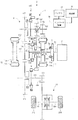
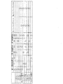
- FIG. 1 is an explanatory view of a vehicle equipped with a hybrid vehicle drive device according to a first embodiment. It is an engagement table of the drive device for hybrid vehicles of 1st embodiment and 2nd embodiment. It is explanatory drawing of the vehicle by which the hybrid vehicle drive device of 2nd embodiment was mounted. It is explanatory drawing of the vehicle by which the hybrid vehicle drive device of 3rd embodiment was mounted. It is an engagement table of the drive device for hybrid vehicles of a third embodiment.
- the vehicle V includes a hybrid vehicle drive device 1, a differential 19, drive shafts 20L and 20R, and drive wheels 21L and 21R.
- the hybrid vehicle drive device 1 includes an engine 2, a flywheel 3, an automatic transmission 4, a first motor generator 11, a second motor generator 12, an inverter device 16, a battery 17, and a control unit 18.
- the engine 2 is a gasoline engine, a diesel engine or the like that uses a hydrocarbon fuel such as gasoline or light oil and outputs the engine torque Te to the drive shaft 2a.
- the flywheel 3 is connected to the drive shaft 2a.
- the flywheel 3 is provided with a damper 3a that absorbs the fluctuation of the input engine torque Te.
- the configuration of the automatic transmission 4 will be described in detail later.
- the first motor generator is composed of a first rotor 11a and a first stator 11b.
- the first rotor 11a is rotatably provided on the inner peripheral side of the first stator 11b.
- the second motor generator 12 is composed of a second rotor 12a and a second stator 12b.
- the second rotor 12a is rotatably provided on the inner peripheral side of the second stator 12b.
- the battery 17 is a secondary battery that stores electric power, and supplies power to the first stator 11 b of the first motor generator 11 and the second stator 12 b of the second motor generator 12 via the inverter device 16.
- the inverter device 16 boosts the voltage of the power supplied from the battery 17 based on the command from the control unit 18 to generate the first stator 11 b of the first motor generator 11 and the second stator 12 b of the second motor generator 12. It supplies and drives the first motor generator 11 and the second motor generator 12. In addition, inverter device 16 steps down the voltage of the electric power generated by first motor generator 11 and second motor generator 12 based on the command from control unit 18 to charge battery 17. When the brake pedal (not shown) is depressed, the control unit 18 outputs a command to the inverter device 16 to cause at least one of the first motor generator 11 and the second motor generator 12 to generate electric power, thereby performing regeneration. Generate a braking force.
- the differential 19 transmits the torque output from the automatic transmission 4 to the left and right drive wheels 21L and 21R via the left and right drive shafts 20L and 20R, and the rotational speed difference between the left and right drive wheels 21L and 21R. Absorb.
- the automatic transmission 4 includes a first input shaft 111, a second input shaft 112, a rotating member 115, a first output shaft 121, a second output shaft 122, a first drive gear 131, a second drive gear 132, and a first driven gear 141.
- the first input shaft 111 (corresponding to the input shaft described in the claims) is provided in series with the drive shaft 2a coaxially with the drive shaft 2a.
- the first input shaft 111 is rotatably connected to the drive shaft 2 a of the engine 2 via the flywheel 3.
- the rotating member 115 has a cylindrical shape and is provided coaxially with the first input shaft 111 on the outer peripheral side of the first input shaft 111.
- the second input shaft 112 is provided coaxially with the first input shaft 111 in series with the first input shaft 111.
- the first output shaft 121 (corresponding to the output shaft described in the claims) and the second output shaft 122 (corresponding to the output shaft described in the claims) have a first input shaft 111 and a second input shaft 112. And are provided in parallel in the radial direction.
- the first rotor 11 a of the first motor generator 11 is rotationally connected to the rotating member 115.
- a one-way clutch 161 (corresponding to a first one-way clutch described in the claims) is provided between the first input shaft 111 and the rotating member 115.
- the one-way clutch 161 is locked.
- the input shaft 111 and the rotating member 115 are connected.
- the one-way clutch 161 is in a free state, and the first input shaft 111 and the rotating member 115 are disconnected.
- the first drive gear 131 is provided on the rotating member 115 so as to be able to idle.
- the second drive gear 132 and the second rotor 12 a of the second motor generator 12 are fixed to the second input shaft 112. With such a configuration, the second drive gear 132 (corresponding to the drive gear described in the claims) is rotationally connected to the second rotor 12 a of the second motor generator 12.
- the first output gear 151 is fixed to the first output shaft 121 and meshes with the ring gear 19 a of the differential 19. With such a configuration, the first output shaft 121 is rotationally connected to the drive wheels 21L and 21R.
- the first driven gear 141 is provided rotatably on the first output shaft 121 and is in mesh with the second drive gear 132. With such a configuration, when the first driven gear 141 is connected to the first output shaft 121 as described later, the second motor generator 12 is rotationally connected to the first output shaft 121.
- the overdrive driven gear 149 is fixed to the second output shaft 122 and meshes with the first drive gear 131. With such a configuration, as described later, when the first drive gear 131 is connected to the rotating member 115 by the first connecting mechanism 191, the rotating member 115 is rotationally connected to the second output shaft 122.
- the second output gear 152 is fixed to the second output shaft 122 and meshes with the ring gear 19 a of the differential 19. With such a configuration, the second output shaft 122 is rotationally connected to the drive wheels 21L and 21R. The gear diameter of the second output gear 152 is larger than the gear diameter of the first output gear 151.
- the second driven gear 142 is rotatably provided on the second output shaft 122 and meshes with the second drive gear 132. With such a configuration, when the second driven gear 142 is connected to the second output shaft 122 as described later, the second motor generator 12 is rotationally connected to the second output shaft 122.
- the gear diameter of the second driven gear 142 is smaller than the gear diameter of the first driven gear 141.
- the first connecting mechanism 191 has a first shift position S1 for connecting the first drive gear 131 to the rotating member 115, a second shift position S2 for connecting the first input shaft 111 to the rotating member 115, a first drive gear 131, and It is a dog clutch which switches to any one of the first neutral N1 in which none of the one input shaft 111 is connected to the rotating member 115.
- the first connection mechanism 191 connects and disconnects either the first drive gear 131 or the first input shaft 111 and the rotating member 115.
- the first connection mechanism 191 includes a first hub 191a, a first engagement member 191b, a second engagement member 191c, a first sleeve 191d, and a first actuator 191e.
- the first hub 191 a is fixed to the rotating member 115.
- the first engagement member 191 b is fixed to the first drive gear 131 and provided adjacent to the first hub 191 a.
- the second engagement member 191 c is fixed to the first input shaft 111 and provided adjacent to the first hub 191 a.
- the first sleeve 191d is in splined engagement with the first hub 191a, and selectively engages either the first engagement member 191b or the second engagement member 191c, and the first engagement member 191b or the second It does not engage with both of the engagement members 191c.
- the first actuator 191e moves the first sleeve 191d to any one of the first neutral N1, the first shift position S1, and the second shift position S2 based on a command from the control unit 18.
- the first hub 191a is not engaged with any of the first engagement member 191b and the second engagement member 191c.
- the first hub 191 a engages with the first engagement member 191 b and the first drive gear 131 is connected to the rotating member 115.
- the first hub 191 a engages with the second engagement member 191 c and the first input shaft 111 is connected to the rotation member 115.
- the second connection mechanism 192 either the third shift position S3 in which the first driven gear 141 is connected to the first output shaft 121 or the second neutral N2 in which the first driven gear 141 is disconnected from the first output shaft 121 It is a dog clutch that switches. In other words, the second connection mechanism 192 connects and disconnects the first driven gear 141 and the first output shaft 121.
- the specific configuration of the second connection mechanism 192 is the same as that of the first connection mechanism 191, so the description will be omitted.
- the third connection mechanism 193 is either the fourth shift position S4 in which the second driven gear 142 is connected to the second output shaft 122 or the third neutral N3 in which the second driven gear 142 is disconnected from the second output shaft 122. It is a dog clutch that switches. In other words, the third connection mechanism 193 connects and disconnects the second driven gear 142 and the second output shaft 122.
- the specific configuration of the third connection mechanism 193 is the same as that of the first connection mechanism 191, so the description will be omitted.
- the EV-L is a mode in which the vehicle V travels with only the driving force of the second motor generator 12.
- the control unit 18 When forming the EV-L in the automatic transmission 4, the control unit 18 outputs a command to the connecting mechanisms 191 to 193 so that the shift position is in the column of EV-L in the engagement table of FIG.
- the first driven gear 141 is coupled to the first output shaft 121
- the second motor generator 12 is rotationally coupled to the driving wheels 21L and 21R.
- the second motor torque Tm2 output from the second motor generator 12 is transmitted to the drive wheels 21L and 21R via the first output shaft 121.
- [EV-H] EV-H is a mode in which the vehicle V travels with only the driving force of the second motor generator 12.
- the reduction ratio between the second motor generator 12 and the drive wheels 21L and 21R is smaller than the reduction ratio of the EV-L.
- the control unit 18 outputs a command to the connecting mechanisms 191 to 193 so that the shift position becomes the column of the EV-H speed in the engagement table of FIG. .
- the second driven gear 142 is coupled to the second output shaft 122, and the second motor generator 12 is rotationally coupled to the driving wheels 21L and 21R. Then, the second motor torque Tm2 output from the second motor generator 12 is transmitted to the drive wheels 21L and 21R via the second output shaft 122.
- [EV-OD] EV-OD is a mode in which the vehicle V travels with the driving force of the first motor generator 11.
- the reduction ratio between the first motor generator 11 and the drive wheels 21L, 21R is smaller than the reduction ratio between the second motor generator 12 and the drive wheels 21L, 21R in EV-H.
- the control unit 18 When forming the EV-OD in the automatic transmission 4, the control unit 18 outputs a command to the connecting mechanisms 191 to 193 so that the shift position is in the column of EV-OD in the engagement table of FIG.
- the first drive gear 131 is connected to the rotating member 115, and the first motor generator 11 is rotationally connected to the driving wheels 21L and 21R.
- the first motor torque Tm1 output from the first motor generator 11 is transmitted to the drive wheels 21L and 21R via the second output shaft 122.
- the EV-OD is formed, and the first motor generator 11 outputs the first motor torque Tm1 to the drive wheels 21L and 21R, whereby the vehicle is produced. Prevent V from decelerating.
- the engine travel is a mode in which the vehicle V travels with the driving force of the engine 2.
- the control unit 18 outputs a command to the connecting mechanisms 191 to 193 so that the shift position becomes a column of the engine travel in the engagement table of FIG.
- the first drive gear 131 is connected to the rotating member 115.
- the one-way clutch 161 is in the locked state, the first input shaft 111 and the rotating member 115 are connected, and the engine torque Te is driven through the second output shaft 122. , 21R.
- the first motor generator 11 is driven by the driving force of the engine 2, and the first motor generator 11 generates electric power and supplies power to the accessories of the vehicle V.
- the vehicle V travels with both the engine 2 and the first motor generator 11 in engine travel.
- the series L is a mode in which the first motor generator 11 is driven by the engine 2, power is generated by the first motor generator 11, and the vehicle V travels by the driving force of the second motor generator 12.
- the control unit 18 When forming the series L in the automatic transmission 4, the control unit 18 outputs a command to the connecting mechanisms 191 to 193 so that the shift position becomes a column of series L in the engagement table of FIG.
- the first driven gear 141 is coupled to the first output shaft 121, and the second motor generator 12 is rotationally coupled to the driving wheels 21L and 21R.
- the engine 2 Since the engine 2 is driven and the first input shaft 111 is rotated, the one-way clutch 161 is locked, the first motor generator 11 is driven by the engine 2, and the first motor generator 11 generates electric power.
- the electric power generated by the first motor generator 11 is used to drive the second motor generator 12, and the second motor torque Tm 2 output from the second motor generator 12 is driven by the driving wheel via the first output shaft 121. It is transmitted to 21L and 21R.
- the series H is a mode in which the first motor generator 11 is driven by the engine 2, power is generated by the first motor generator 11, and the vehicle V travels by the driving force of the second motor generator 12.
- the reduction ratio between the second motor generator 12 and the drive wheels 21L and 21R is smaller than the reduction ratio of the series L.
- the control unit 18 When forming the series H in the automatic transmission 4, the control unit 18 outputs a command to the connecting mechanisms 191 to 193 so that the shift position becomes a column of series H in the engagement table of FIG.
- the second driven gear 142 is connected to the second output shaft 122, and the second motor generator 12 is rotationally connected to the drive wheels 21L and 21R.
- the engine 2 Since the engine 2 is driven and the first input shaft 111 is rotated, the one-way clutch 161 is locked, the first motor generator 11 is driven by the engine 2, and the first motor generator 11 generates electric power.
- the electric power generated by the first motor generator 11 is used to drive the second motor generator 12, and the second motor torque Tm 2 output from the second motor generator 12 is driven by the driving wheel via the second output shaft 122. It is transmitted to 21L and 21R.
- the parallel L is a mode in which the vehicle V travels with the driving force of the engine 2 and the second motor generator 12.
- the control unit 18 When forming the parallel L in the automatic transmission 4, the control unit 18 outputs a command to the connecting mechanisms 191 to 193 so that the shift position is a column of the parallel L in the engagement table of FIG.
- the parallel L is formed in the automatic transmission 4, the first drive gear 131 is connected to the rotating member 115, and the first motor generator 11 is rotationally connected to the driving wheels 21L and 21R. Further, the first driven gear 141 is connected to the first output shaft 121.
- the one-way clutch 161 is locked, and the engine torque Te output from the engine 2 is transmitted to the first motor generator 11 and the drive wheels 21L and 21R. Ru.
- the electric power generated by the first motor generator 11 is used to drive the second motor generator 12.
- the second motor torque Tm2 output from the second motor generator 12 is transmitted to the drive wheels 21L and 21R via the first output shaft 121.
- the first motor generator 11 operates as a motor, and the first motor torque Tm1 output from the first motor generator 11 is transmitted to the drive wheels 21L and 21R via the second output shaft 122. Ru.
- the parallel H is a mode in which the vehicle V travels by the driving force of the engine 2 and the second motor generator 12.
- the reduction ratio between the second motor generator 12 and the drive wheels 21L and 21R is smaller than the reduction ratio of the parallel L.
- the control unit 18 outputs a command to the connecting mechanisms 191 to 193 so that the shift position becomes a column of the parallel H in the engagement table of FIG.
- the parallel H is formed in the automatic transmission 4, the first drive gear 131 is connected to the rotating member 115, and the first motor generator 11 is rotationally connected to the driving wheels 21L and 21R.
- a second driven gear 142 is connected to the second output shaft 122.
- the one-way clutch 161 is locked, and the engine torque Te output from the engine 2 is transmitted to the first motor generator 11 and the drive wheels 21L and 21R.
- the electric power generated by the first motor generator 11 is used to drive the second motor generator 12, and the second motor torque Tm 2 output from the second motor generator 12 is driven by the driving wheel via the second output shaft 122. It is transmitted to 21L and 21R.
- the first motor generator 11 operates as a motor, and the first motor torque Tm1 output from the first motor generator 11 is transmitted to the drive wheels 21L and 21R via the second output shaft 122. Ru.
- the engine start is a mode in which the first motor generator 11 starts the engine 2.
- the control unit 18 When forming an engine start in the automatic transmission 4, the control unit 18 outputs a command to the connecting mechanisms 191 to 193 so that the shift position becomes a column of the engine start in the engagement table of FIG.
- the first rotor 11 a of the first motor generator 11 When the engine start is formed in the automatic transmission 4, the first rotor 11 a of the first motor generator 11 is connected to the first input shaft 111.
- the first motor torque Tm1 output from the first motor generator 11 is transmitted to the engine 2 and the engine 2 is started.
- the hybrid vehicle drive device 1 is low in cost since the one-way clutch 161 is low in cost as compared with the configuration using the friction clutch connecting the first input shaft 111 and the rotating member 115, the hybrid vehicle drive device 1 is low in cost.
- the first connection mechanism 191 connects and disconnects the second output shaft 122 and the rotating member 115 by connecting and disconnecting the first drive gear 131 and the rotating member 115.
- the first motor generator 11 and the engine 2 can be separated from the second output shaft 122. Therefore, it is possible to switch to the EV-L mode or the EV-H mode in which the vehicle travels with only the driving force of the second motor generator 12. Further, it is possible to drive the first motor generator 11 by the engine 2 and switch to the series L mode or the series H mode in which the first motor generator 11 generates electric power and travels by the driving force of the second motor generator 12. As a result, it is possible to switch to an appropriate travel mode according to the vehicle speed of the vehicle V, the remaining amount of the battery 17, and the required driving force.
- the first connection mechanism 191 connects and disconnects the first input shaft 111 and the rotating member 115.
- the first rotor 11a of the first motor generator 11 can be connected to the engine 2.
- the engine 2 can be started by the first motor generator 11, and a dedicated motor for starting the engine 2 is not necessary, and the cost of the hybrid vehicle drive device 1 can be reduced.
- the hybrid vehicle drive device 1 of the second embodiment will be described based on FIG. 3 with respect to differences from the hybrid vehicle drive device 1 of the first embodiment.
- the hybrid vehicle drive system 1 of the second embodiment has the same structure as that of the hybrid vehicle drive system 1 of the first embodiment. Do.
- both front and rear wheels are drive wheels 21FL, 21FR, 21RL, and 21RR.
- at least one of the engine 2 and the first motor generator 11 is one of the front and rear drive wheels 21FL, 21FR, 21RL, and 21RR.
- the second motor generator 12 drives the other drive wheel among the front and rear drive wheels 21FL, 21FR, 21RL, and 21RR.
- a first output shaft 125 is provided in parallel with the first input shaft 111 in the radial direction.
- the first output gear 151 and the overdrive driven gear 149 are fixed to the first output shaft 125.
- the rotating member 115 is rotatably connected to the first output shaft 125.
- the first output gear 151 meshes with the front ring gear 19Fa of the front differential 19F.
- the front drive wheels 21FL and 21FR are rotationally connected via the front drive shafts 20FL and 20FR.
- the first output shaft 125 is rotationally connected to the front drive wheels 21FL and 21FR.
- a low-side second output shaft 126 (corresponding to a second output shaft as recited in the claims) and a high-side second output shaft 127 (as recited in the claims) are provided in parallel with the second input shaft 112 in the radial direction. (Corresponding to two output shafts) is provided.
- a second output gear 152 is fixed to the low side second output shaft 126.
- the second output gear 152 meshes with the rear ring gear 19Ra of the rear differential 19R.
- the rear drive wheels 21RL and 21RR are rotationally connected via the rear drive shafts 20RL and 20RR.
- the low side second output shaft 126 is rotationally connected to the rear side drive wheels 21RL and 21RR.
- a first driven gear 141 is rotatably provided on the low side second output shaft 126.
- the second connection mechanism 192 connects and disconnects the first driven gear 141 and the low side second output shaft 126.
- the first driven gear 141 is connected to the low side second output shaft 126 by the second connecting mechanism 192
- the second rotor 12 a of the second motor generator 12 is rotationally connected to the low side second output shaft 126.
- the low side second output shaft 126 is rotatably connected to the second rotor 12 a of the second motor generator 12.
- the third output gear 153 is fixed to the high side second output shaft 127.
- the third output gear 153 meshes with the rear ring gear 19Ra of the rear differential 19R.
- a second driven gear 142 is provided on the high side second output shaft 127 so as to be capable of free rotation.
- the third connection mechanism 193 connects and disconnects the second driven gear 142 and the high side second output shaft 127.
- the second driven gear 142 is connected to the high side second output shaft 127 by the third connection mechanism 193
- the second rotor 12a of the second motor generator 12 is rotationally connected to the high side second output shaft 127.
- the control unit 18 outputs commands to the connection mechanisms 191 to 193 according to the engagement table shown in FIG. 2 to set the hybrid vehicle drive device 1 in each mode.
- the front drive wheels 21FL and 21FR and the rear drive wheels 21RL and 21RR can be simultaneously driven. For this reason, it is possible to suppress slippage of the front and rear drive wheels 21FL, 21FR, 21RL, 21R in a situation where the front and rear drive wheels 21FL, 21FR, 21RL, 21RR are slippery, such as on a snowy road.
- the first output shaft 125 is rotatably connected to the rear drive wheels 21RL and 21RR, and the low side second output shaft 126 and the high side second output shaft 127 are rotatably connected to the front drive wheels 21FL and 21FR. It does not matter. That is, in the embodiment, at least one of the engine 2 and the first motor generator 11 drives the rear drive wheels 21RL and 21RR, and the second motor generator 12 drives the front drive wheels 21FL and 21FR.
- the hybrid vehicle drive device 1 of the third embodiment will be described based on FIG. 4 with respect to differences from the hybrid vehicle drive device 1 of the first embodiment.
- the hybrid vehicle drive device 1 of the third embodiment has the same structure as that of the hybrid vehicle drive device 1 of the first embodiment, and in FIG. Do.
- a second one-way clutch 162 is provided between the overdrive driven gear 149 (connection member) and the second output shaft 122.
- the second one-way clutch 162 is locked when the rotational speed of the overdrive driven gear 149 (coupling member) is faster than the rotational speed of the second output shaft 122, and connects the overdrive driven gear 149 to the second output shaft 122 .
- the second one-way clutch 162 is free and cuts the overdrive driven gear 149 and the second output shaft 122.
- the overdrive driven gear 149 (connection member) is rotatably connected to the rotation member 115.
- the rotational speed of the overdrive driven gear 149 becomes faster than the rotational speed of the second output shaft 122 by driving of the first motor generator 11 or the engine 2
- the second one-way clutch 162 is locked and the overdrive driven gear 149 (coupling member) is coupled to the second output shaft 122.
- the engine torque Te and the first motor torque Tm1 are transmitted to the drive wheels 21L and 21R via the second output shaft 122.
- the control unit 18 outputs commands to the connection mechanisms 191 to 193 according to the engagement table shown in FIG. 5 to set the hybrid vehicle drive device 1 in each mode.
- the first rotor 11a of the first motor generator 11 is connected to the first drive gear 131 in each of the EV-L and EH-H modes.
- the first motor generator 11 is the first The motor torque Tm1 is output.
- the second one-way clutch 162 is locked, and the first rotor 11a of the first motor generator 11 is automatically connected to the second output shaft 122, and the driving wheel 21L is driven by the first motor torque Tm1 of the first motor generator 11. , 21R are driven.
- the first rotor 11a of the first motor generator 11 is connected in advance to the first drive gear 131, the first rotor 11a of the first motor generator 11 is required when the driving force of the first motor generator 11 is required. There is no need to connect the first drive gear 131, and the drive wheels 21L and 21R can be driven immediately by the first motor generator 11.
- the second one-way clutch 162 becomes free, and the first rotor 11a of the first motor generator 11 is disconnected from the second output shaft 122. Therefore, it is possible to prevent the occurrence of loss due to the rotation of the first rotor 11a of the first motor generator 11.
- first connection mechanism 191 to the third connection mechanism 193 are dog clutches.
- first connection mechanism 191 to the third connection mechanism 193 may be synchronizer mechanisms.
- second connection mechanism 192 and the third connection mechanism 193 can be operated by the same actuator.
Landscapes
- Engineering & Computer Science (AREA)
- Mechanical Engineering (AREA)
- Transportation (AREA)
- Combustion & Propulsion (AREA)
- Chemical & Material Sciences (AREA)
- Power Engineering (AREA)
- General Engineering & Computer Science (AREA)
- Sustainable Energy (AREA)
- Sustainable Development (AREA)
- Life Sciences & Earth Sciences (AREA)
- Hybrid Electric Vehicles (AREA)
- Electric Propulsion And Braking For Vehicles (AREA)
- Structure Of Transmissions (AREA)
Abstract
エンジンを出力軸に接続する際に、ハイブリッド車両用駆動装置を構成するギヤに過大な力が作用しないハイブリッド車両用駆動装置を提供する。ハイブリッド車両用駆動装置は、第一モータジェネレータと、第二モータジェネレータと、エンジンが回転連結される第一入力軸と、駆動輪及び第二モータジェネレータに回転連結される第二出力軸と、第一モータジェネレータ及び第二出力軸に回転連結される回転部材と、第一入力軸の回転速度が回転部材の回転速度よりも速い場合に、第一入力軸と回転部材とを接続し、第一入力軸の回転速度が回転部材の回転速度よりも遅い場合に、第一入力軸と回転部材とを切断する第一ワンウエイクラッチと、を有する。
Description
本発明は、ハイブリッド車両用駆動装置に関する。
従来から特許文献1に示されるように、2つのモータジェネレータとエンジンを備えたハイブリッド車両用駆動装置が提案されている。このハイブリッド車両用駆動装置は、エンジンと出力軸とを断接するための第一クラッチと、第一モータジェネレータと出力軸とを断接する第二クラッチとを有している。
特許文献1に示されるハイブリッド車両用駆動装置では、エンジンが出力するエンジントルクを出力軸に伝達させる際に、切断状態にある第一クラッチを接続する。この際に、第一クラッチが接続する部材同士に回転速度差があり、エンジンの慣性力が、第一クラッチを介して、ハイブリッド車両用駆動装置を構成するギヤに入力され、このギヤに過大な力が作用し、ギヤに悪影響を与える。
本発明は、上述した問題を解消するためになされたもので、モータジェネレータとエンジンを有するハイブリッド車両用駆動装置において、エンジンを出力軸に接続する際に、ハイブリッド車両用駆動装置を構成するギヤに過大な力が作用しないハイブリッド車両用駆動装置を提供する。
上記の課題を解決するため、請求項1に係るハイブリッド車両用駆動装置の発明は、第一モータジェネレータと、第二モータジェネレータと、エンジンが回転連結される入力軸と、駆動輪及び前記第二モータジェネレータに回転連結される出力軸と、前記第一モータジェネレータ及び前記出力軸に回転連結される回転部材と、前記入力軸の回転速度が前記回転部材の回転速度よりも速い場合に、前記入力軸と前記回転部材とを接続し、前記入力軸の回転速度が前記回転部材の回転速度よりも遅い場合に、前記入力軸と前記回転部材とを切断する第一ワンウエイクラッチと、を有する。
このように、第一ワンウエイクラッチは、入力軸の回転速度が回転部材の回転速度よりも速い場合に、入力軸と回転部材とを接続する。これにより、エンジンがエンジントルクを出力して、入力軸の回転速度が回転部材の回転速度よりも速くなると、第一ワンウエイクラッチによって、入力軸と回転部材とが接続され、エンジンと出力軸が接続される。つまり、入力軸と回転部材との回転速度差が無い状態で、第一ワンウエイクラッチによって、入力軸と回転部材とが接続される。このため、ハイブリッド車両用駆動装置を構成する各ギヤにエンジンの慣性力による力が入力されず、ハイブリッド車両用駆動装置を構成するギヤに過大な力が作用しない。
(車両の説明)
図1に基づき、本発明の実施形態(第一実施形態)によるハイブリッド車両用駆動装置1が搭載された車両Vについて説明する。図1に示すように、車両Vは、ハイブリッド車両用駆動装置1、デファレンシャル19、ドライブシャフト20L、20R、及び駆動輪21L、21Rを有している。ハイブリッド車両用駆動装置1は、エンジン2、フライホイール3、自動変速機4、第一モータジェネレータ11、第二モータジェネレータ12、インバータ装置16、バッテリ17、及び制御部18を有している。
図1に基づき、本発明の実施形態(第一実施形態)によるハイブリッド車両用駆動装置1が搭載された車両Vについて説明する。図1に示すように、車両Vは、ハイブリッド車両用駆動装置1、デファレンシャル19、ドライブシャフト20L、20R、及び駆動輪21L、21Rを有している。ハイブリッド車両用駆動装置1は、エンジン2、フライホイール3、自動変速機4、第一モータジェネレータ11、第二モータジェネレータ12、インバータ装置16、バッテリ17、及び制御部18を有している。
エンジン2は、ガソリンや軽油等の炭化水素系燃料を使用し、エンジントルクTeをその駆動軸2aに出力するガソリンエンジンやディーゼルエンジン等である。フライホイール3は、駆動軸2aに連結されている。フライホイール3には、入力されたエンジントルクTeの変動を吸収するダンパー3aが設けられている。自動変速機4の構成については、後で詳細に説明する。
第一モータジェネレータは、第一ロータ11aと第一ステータ11bとから構成されている。第一ロータ11aは、第一ステータ11bの内周側に回転可能に設けられている。第二モータジェネレータ12は、第二ロータ12aと第二ステータ12bとから構成されている。第二ロータ12aは、第二ステータ12bの内周側に回転可能に設けられている。
バッテリ17は、電力を蓄電する二次電池であり、インバータ装置16を介して、第一モータジェネレータ11の第一ステータ11b及び第二モータジェネレータ12の第二ステータ12bに電力を供給する。
バッテリ17は、電力を蓄電する二次電池であり、インバータ装置16を介して、第一モータジェネレータ11の第一ステータ11b及び第二モータジェネレータ12の第二ステータ12bに電力を供給する。
インバータ装置16は、制御部18からの指令に基づいて、バッテリ17から供給された電力の電圧を昇圧して第一モータジェネレータ11の第一ステータ11b及び第二モータジェネレータ12の第二ステータ12bに供給し、第一モータジェネレータ11及び第二モータジェネレータ12を駆動する。また、インバータ装置16は、制御部18からの指令に基づいて、第一モータジェネレータ11及び第二モータジェネレータ12において発電された電力の電圧を降圧して、バッテリ17に充電する。ブレーキペダル(不図示)が踏まれた場合には、制御部18は、インバータ装置16に指令を出力して、第一モータジェネレータ11及び第二モータジェネレータ12の少なくとも一方において発電をさせて、回生制動力を発生させる。
デファレンシャル19は、自動変速機4から出力されたトルクを、左右のドライブシャフト20L、20Rを介して、左右の駆動輪21L、21Rに伝達するとともに、左右の駆動輪21L、21Rの回転速度差を吸収する。
(自動変速機)
以下に、自動変速機4について説明する。自動変速機4は、第一入力軸111、第二入力軸112、回転部材115、第一出力軸121、第二出力軸122、第一ドライブギヤ131、第二ドライブギヤ132、第一ドリブンギヤ141、第二ドリブンギヤ142、オーバードライブドリブンギヤ149、第一出力ギヤ151、第二出力ギヤ152、ワンウエイクラッチ161、第一連結機構191、第二連結機構192、及び第三連結機構193を有している。
以下に、自動変速機4について説明する。自動変速機4は、第一入力軸111、第二入力軸112、回転部材115、第一出力軸121、第二出力軸122、第一ドライブギヤ131、第二ドライブギヤ132、第一ドリブンギヤ141、第二ドリブンギヤ142、オーバードライブドリブンギヤ149、第一出力ギヤ151、第二出力ギヤ152、ワンウエイクラッチ161、第一連結機構191、第二連結機構192、及び第三連結機構193を有している。
第一入力軸111(特許請求の範囲に記載の入力軸に相当)は、駆動軸2aと同軸に、駆動軸2aと直列に設けられている。第一入力軸111は、フライホイール3を介してエンジン2の駆動軸2aに回転連結されている。回転部材115は、円筒形状であり、第一入力軸111の外周側に、第一入力軸111と同軸に設けられている。第二入力軸112は、第一入力軸111と同軸に、第一入力軸111と直列に設けられている。第一出力軸121(特許請求の範囲に記載の出力軸に相当)及び第二出力軸122(特許請求の範囲に記載の出力軸に相当)は、第一入力軸111及び第二入力軸112と径方向に並列に設けられている。
第一モータジェネレータ11の第一ロータ11aは、回転部材115に回転連結されている。第一入力軸111と回転部材115との間には、ワンウエイクラッチ161(特許請求の範囲に記載の第一ワンウエイクラッチに相当)が設けられている。第一入力軸111の回転速度、つまり、エンジン2の回転速度が、回転部材115の回転速度、つまり、第一ロータ11aの回転速度よりも速い場合に、ワンウエイクラッチ161はロック状態となり、第一入力軸111と回転部材115とが接続される。一方で、第一入力軸111の回転速度が回転部材115の回転速度よりも遅い場合には、ワンウエイクラッチ161はフリー状態となり、第一入力軸111と回転部材115とが切断される。第一ドライブギヤ131は、回転部材115に遊転可能に設けられている。
第二ドライブギヤ132及び第二モータジェネレータ12の第二ロータ12aは、第二入力軸112に固定されている。このような構成によって、第二ドライブギヤ132(特許請求の範囲に記載のドライブギヤに相当)は、第二モータジェネレータ12の第二ロータ12aに回転連結されている。
第一出力ギヤ151は、第一出力軸121に固定され、デファレンシャル19のリングギヤ19aと噛み合っている。このような構成によって、第一出力軸121は、駆動輪21L、21Rに回転連結されている。第一ドリブンギヤ141は、第一出力軸121に遊転可能に設けられ、第二ドライブギヤ132と噛み合っている。このような構成によって、後述するように、第一ドリブンギヤ141が第一出力軸121に連結されると、第二モータジェネレータ12が第一出力軸121に回転連結される。
オーバードライブドリブンギヤ149は、第二出力軸122に固定され、第一ドライブギヤ131と噛み合っている。このような構成によって、後述するように、第一連結機構191によって、第一ドライブギヤ131が回転部材115に連結されると、回転部材115は第二出力軸122に回転連結される。
第二出力ギヤ152は、第二出力軸122に固定され、デファレンシャル19のリングギヤ19aと噛み合っている。このような構成によって、第二出力軸122は、駆動輪21L、21Rに回転連結されている。第二出力ギヤ152のギヤ径は、第一出力ギヤ151のギヤ径よりも大きくなっている。
第二ドリブンギヤ142は、第二出力軸122に遊転可能に設けられ、第二ドライブギヤ132と噛み合っている。このような構成によって、後述するように、第二ドリブンギヤ142が第二出力軸122に連結されると、第二モータジェネレータ12が第二出力軸122に回転連結される。第二ドリブンギヤ142のギヤ径は、第一ドリブンギヤ141のギヤ径よりも小さくなっている。
第一連結機構191は、第一ドライブギヤ131を回転部材115に連結する第一シフトポジションS1、第一入力軸111を回転部材115に連結する第二シフトポジションS2、第一ドライブギヤ131及び第一入力軸111のいずれも回転部材115に連結しない第一ニュートラルN1のいずれかに切り換えるドグクラッチである。言い換えると、第一連結機構191は、第一ドライブギヤ131又は第一入力軸111のいずれかと回転部材115とを断接する。第一連結機構191は、第一ハブ191a、第一係合部材191b、第二係合部材191c、第一スリーブ191d、及び第一アクチュエータ191eから構成されている。
第一ハブ191aは、回転部材115に固定されている。第一係合部材191bは、第一ドライブギヤ131に固定され、第一ハブ191aに隣接して設けられている。第二係合部材191cは、第一入力軸111に固定され、第一ハブ191aに隣接して設けられている。第一スリーブ191dは、第一ハブ191aとスプライン嵌合していて、第一係合部材191b及び第二係合部材191cのいずれかと選択的に係合し、第一係合部材191b及び第二係合部材191cの両方と係合しない。
第一アクチュエータ191eは、制御部18の指令に基づいて、第一スリーブ191dを、第一ニュートラルN1、第一シフトポジションS1、及び第二シフトポジションS2のいずれに移動させる。第一スリーブ191dが第一ニュートラルN1に位置している状態では、第一ハブ191aは、第一係合部材191b及び第二係合部材191cのいずれにも係合していない。第一スリーブ191dが第一シフトポジションS1に位置している状態では、第一ハブ191aは第一係合部材191bに係合し、第一ドライブギヤ131は回転部材115に連結される。第一スリーブ191dが第二シフトポジションS2に位置している状態では、第一ハブ191aは第二係合部材191cに係合し、第一入力軸111は回転部材115に連結される。
第二連結機構192は、第一ドリブンギヤ141が第一出力軸121に連結された第三シフトポジションS3と、第一ドリブンギヤ141が第一出力軸121から切断された第二ニュートラルN2のいずれかに切り換えるドグクラッチである。言い換えると、第二連結機構192は、第一ドリブンギヤ141と第一出力軸121を断接する。第二連結機構192の具体的な構成は、第一連結機構191と同様であるので、説明を省略する。
第三連結機構193は、第二ドリブンギヤ142が第二出力軸122に連結された第四シフトポジションS4と、第二ドリブンギヤ142が第二出力軸122から切断された第三ニュートラルN3のいずれかに切り換えるドグクラッチである。言い換えると、第三連結機構193は、第二ドリブンギヤ142と第二出力軸122とを断接する。第三連結機構193の具体的な構成は、第一連結機構191と同様であるので、説明を省略する。
(第一実施形態のハイブリッド車両用駆動装置のモード)
次に、図2に示す係合表を用いて、第一実施形態のハイブリッド車両用駆動装置1のモードについて説明する。
次に、図2に示す係合表を用いて、第一実施形態のハイブリッド車両用駆動装置1のモードについて説明する。
[EV-L]
EV-Lは、第二モータジェネレータ12の駆動力のみで車両Vが走行するモードである。制御部18は、自動変速機4においてEV-Lを形成する場合には、シフトポジションが図2の係合表のEV-Lの欄となるように連結機構191~193に指令を出力する。自動変速機4においてEV-Lが形成されると、第一ドリブンギヤ141が第一出力軸121に連結されて、第二モータジェネレータ12が駆動輪21L、21Rに回転連結される。すると、第二モータジェネレータ12から出力された第二モータトルクTm2が、第一出力軸121を介して、駆動輪21L、21Rに伝達される。
EV-Lは、第二モータジェネレータ12の駆動力のみで車両Vが走行するモードである。制御部18は、自動変速機4においてEV-Lを形成する場合には、シフトポジションが図2の係合表のEV-Lの欄となるように連結機構191~193に指令を出力する。自動変速機4においてEV-Lが形成されると、第一ドリブンギヤ141が第一出力軸121に連結されて、第二モータジェネレータ12が駆動輪21L、21Rに回転連結される。すると、第二モータジェネレータ12から出力された第二モータトルクTm2が、第一出力軸121を介して、駆動輪21L、21Rに伝達される。
[EV-H]
EV-Hは、第二モータジェネレータ12の駆動力のみで車両Vが走行するモードである。EV-Hでは、第二モータジェネレータ12と駆動輪21L、21Rとの間の減速比は、EV-Lの前記減速比よりも小さい。制御部18は、自動変速機4においてEV-Hを形成する場合には、シフトポジションが図2の係合表のEV-H速の欄となるように連結機構191~193に指令を出力する。自動変速機4においてEV-Hが形成されると、第二ドリブンギヤ142が第二出力軸122に連結されて、第二モータジェネレータ12が駆動輪21L、21Rに回転連結される。すると、第二モータジェネレータ12から出力された第二モータトルクTm2が、第二出力軸122を介して、駆動輪21L、21Rに伝達される。
EV-Hは、第二モータジェネレータ12の駆動力のみで車両Vが走行するモードである。EV-Hでは、第二モータジェネレータ12と駆動輪21L、21Rとの間の減速比は、EV-Lの前記減速比よりも小さい。制御部18は、自動変速機4においてEV-Hを形成する場合には、シフトポジションが図2の係合表のEV-H速の欄となるように連結機構191~193に指令を出力する。自動変速機4においてEV-Hが形成されると、第二ドリブンギヤ142が第二出力軸122に連結されて、第二モータジェネレータ12が駆動輪21L、21Rに回転連結される。すると、第二モータジェネレータ12から出力された第二モータトルクTm2が、第二出力軸122を介して、駆動輪21L、21Rに伝達される。
[EV-OD]
EV-ODは、第一モータジェネレータ11の駆動力で車両Vが走行するモードである。EV-ODでは、第一モータジェネレータ11と駆動輪21L、21Rとの間の減速比は、EV-Hにおける第二モータジェネレータ12と駆動輪21L、21Rとの間の減速比よりも小さい。制御部18は、自動変速機4においてEV-ODを形成する場合には、シフトポジションが図2の係合表のEV-ODの欄となるように連結機構191~193に指令を出力する。自動変速機4においてEV-ODが形成されると、第一ドライブギヤ131が回転部材115に連結され、第一モータジェネレータ11が駆動輪21L、21Rに回転連結される。すると、第一モータジェネレータ11から出力された第一モータトルクTm1が、第二出力軸122を介して、駆動輪21L、21Rに伝達される。なお、EV-LとEV-Hとの間で変速する間に、EV-ODを形成して、第一モータジェネレータ11から第一モータトルクTm1を駆動輪21L、21Rを出力することにより、車両Vの減速を防止する。
EV-ODは、第一モータジェネレータ11の駆動力で車両Vが走行するモードである。EV-ODでは、第一モータジェネレータ11と駆動輪21L、21Rとの間の減速比は、EV-Hにおける第二モータジェネレータ12と駆動輪21L、21Rとの間の減速比よりも小さい。制御部18は、自動変速機4においてEV-ODを形成する場合には、シフトポジションが図2の係合表のEV-ODの欄となるように連結機構191~193に指令を出力する。自動変速機4においてEV-ODが形成されると、第一ドライブギヤ131が回転部材115に連結され、第一モータジェネレータ11が駆動輪21L、21Rに回転連結される。すると、第一モータジェネレータ11から出力された第一モータトルクTm1が、第二出力軸122を介して、駆動輪21L、21Rに伝達される。なお、EV-LとEV-Hとの間で変速する間に、EV-ODを形成して、第一モータジェネレータ11から第一モータトルクTm1を駆動輪21L、21Rを出力することにより、車両Vの減速を防止する。
[エンジン走行]
エンジン走行は、エンジン2の駆動力で車両Vが走行するモードである。制御部18は、自動変速機4においてエンジン走行を形成する場合には、シフトポジションが図2の係合表のエンジン走行の欄となるように連結機構191~193に指令を出力する。自動変速機4においてエンジン走行が形成されると、第一ドライブギヤ131が回転部材115に連結される。そして、エンジン2がエンジントルクTeを出力すると、ワンウエイクラッチ161がロック状態となり、第一入力軸111と回転部材115とが接続され、エンジントルクTeが第二出力軸122を介して、駆動輪21L、21Rに伝達される。この場合には、エンジン2の駆動力で第一モータジェネレータ11が駆動されて、第一モータジェネレータ11が発電して車両Vの補機類に電力を供給する。また、要求される駆動力が大きい場合には、エンジン走行において、車両Vは、エンジン2と第一モータジェネレータ11の両方の駆動力で走行する。
エンジン走行は、エンジン2の駆動力で車両Vが走行するモードである。制御部18は、自動変速機4においてエンジン走行を形成する場合には、シフトポジションが図2の係合表のエンジン走行の欄となるように連結機構191~193に指令を出力する。自動変速機4においてエンジン走行が形成されると、第一ドライブギヤ131が回転部材115に連結される。そして、エンジン2がエンジントルクTeを出力すると、ワンウエイクラッチ161がロック状態となり、第一入力軸111と回転部材115とが接続され、エンジントルクTeが第二出力軸122を介して、駆動輪21L、21Rに伝達される。この場合には、エンジン2の駆動力で第一モータジェネレータ11が駆動されて、第一モータジェネレータ11が発電して車両Vの補機類に電力を供給する。また、要求される駆動力が大きい場合には、エンジン走行において、車両Vは、エンジン2と第一モータジェネレータ11の両方の駆動力で走行する。
[シリーズL]
シリーズLは、エンジン2で第一モータジェネレータ11を駆動して、第一モータジェネレータ11において発電し、第二モータジェネレータ12の駆動力で車両Vが走行するモードである。制御部18は、自動変速機4においてシリーズLを形成する場合には、シフトポジションが図2の係合表のシリーズLの欄となるように連結機構191~193に指令を出力する。自動変速機4においてシリーズLが形成されると、第一ドリブンギヤ141が第一出力軸121に連結され、第二モータジェネレータ12が駆動輪21L、21Rに回転連結される。エンジン2が駆動して、第一入力軸111が回転するので、ワンウエイクラッチ161がロックして、エンジン2によって第一モータジェネレータ11が駆動されて、第一モータジェネレータ11において発電される。第一モータジェネレータ11において発電された電力は、第二モータジェネレータ12の駆動に使用され、第二モータジェネレータ12から出力された第二モータトルクTm2が、第一出力軸121を介して、駆動輪21L、21Rに伝達される。
シリーズLは、エンジン2で第一モータジェネレータ11を駆動して、第一モータジェネレータ11において発電し、第二モータジェネレータ12の駆動力で車両Vが走行するモードである。制御部18は、自動変速機4においてシリーズLを形成する場合には、シフトポジションが図2の係合表のシリーズLの欄となるように連結機構191~193に指令を出力する。自動変速機4においてシリーズLが形成されると、第一ドリブンギヤ141が第一出力軸121に連結され、第二モータジェネレータ12が駆動輪21L、21Rに回転連結される。エンジン2が駆動して、第一入力軸111が回転するので、ワンウエイクラッチ161がロックして、エンジン2によって第一モータジェネレータ11が駆動されて、第一モータジェネレータ11において発電される。第一モータジェネレータ11において発電された電力は、第二モータジェネレータ12の駆動に使用され、第二モータジェネレータ12から出力された第二モータトルクTm2が、第一出力軸121を介して、駆動輪21L、21Rに伝達される。
[シリーズH]
シリーズHは、エンジン2で第一モータジェネレータ11を駆動して、第一モータジェネレータ11において発電し、第二モータジェネレータ12の駆動力で車両Vが走行するモードである。シリーズHでは、第二モータジェネレータ12と駆動輪21L、21Rとの間の減速比は、シリーズLの前記減速比よりも小さい。制御部18は、自動変速機4においてシリーズHを形成する場合には、シフトポジションが図2の係合表のシリーズHの欄となるように連結機構191~193に指令を出力する。自動変速機4においてシリーズHが形成されると、第二ドリブンギヤ142が第二出力軸122に連結され、第二モータジェネレータ12が駆動輪21L、21Rに回転連結される。エンジン2が駆動して、第一入力軸111が回転するので、ワンウエイクラッチ161がロックして、エンジン2によって第一モータジェネレータ11が駆動されて、第一モータジェネレータ11において発電される。第一モータジェネレータ11において発電された電力は、第二モータジェネレータ12の駆動に使用され、第二モータジェネレータ12から出力された第二モータトルクTm2が、第二出力軸122を介して、駆動輪21L、21Rに伝達される。
シリーズHは、エンジン2で第一モータジェネレータ11を駆動して、第一モータジェネレータ11において発電し、第二モータジェネレータ12の駆動力で車両Vが走行するモードである。シリーズHでは、第二モータジェネレータ12と駆動輪21L、21Rとの間の減速比は、シリーズLの前記減速比よりも小さい。制御部18は、自動変速機4においてシリーズHを形成する場合には、シフトポジションが図2の係合表のシリーズHの欄となるように連結機構191~193に指令を出力する。自動変速機4においてシリーズHが形成されると、第二ドリブンギヤ142が第二出力軸122に連結され、第二モータジェネレータ12が駆動輪21L、21Rに回転連結される。エンジン2が駆動して、第一入力軸111が回転するので、ワンウエイクラッチ161がロックして、エンジン2によって第一モータジェネレータ11が駆動されて、第一モータジェネレータ11において発電される。第一モータジェネレータ11において発電された電力は、第二モータジェネレータ12の駆動に使用され、第二モータジェネレータ12から出力された第二モータトルクTm2が、第二出力軸122を介して、駆動輪21L、21Rに伝達される。
[パラレルL]
パラレルLは、エンジン2及び第二モータジェネレータ12の駆動力で車両Vが走行するモードである。制御部18は、自動変速機4においてパラレルLを形成する場合には、シフトポジションが図2の係合表のパラレルLの欄となるように連結機構191~193に指令を出力する。自動変速機4においてパラレルLが形成されると、第一ドライブギヤ131が回転部材115に連結され、第一モータジェネレータ11が駆動輪21L、21Rに回転連結される。また、第一ドリブンギヤ141が第一出力軸121に連結される。エンジン2が駆動して、第一入力軸111が回転するので、ワンウエイクラッチ161がロックして、エンジン2から出力されたエンジントルクTeは、第一モータジェネレータ11及び駆動輪21L、21Rに伝達される。第一モータジェネレータ11において発電された電力は、第二モータジェネレータ12の駆動に使用される。第二モータジェネレータ12から出力された第二モータトルクTm2が、第一出力軸121を介して、駆動輪21L、21Rに伝達される。また、場合によっては、第一モータジェネレータ11は電動機として作動し、第一モータジェネレータ11から出力された第一モータトルクTm1が、第二出力軸122を介して、駆動輪21L、21Rに伝達される。
パラレルLは、エンジン2及び第二モータジェネレータ12の駆動力で車両Vが走行するモードである。制御部18は、自動変速機4においてパラレルLを形成する場合には、シフトポジションが図2の係合表のパラレルLの欄となるように連結機構191~193に指令を出力する。自動変速機4においてパラレルLが形成されると、第一ドライブギヤ131が回転部材115に連結され、第一モータジェネレータ11が駆動輪21L、21Rに回転連結される。また、第一ドリブンギヤ141が第一出力軸121に連結される。エンジン2が駆動して、第一入力軸111が回転するので、ワンウエイクラッチ161がロックして、エンジン2から出力されたエンジントルクTeは、第一モータジェネレータ11及び駆動輪21L、21Rに伝達される。第一モータジェネレータ11において発電された電力は、第二モータジェネレータ12の駆動に使用される。第二モータジェネレータ12から出力された第二モータトルクTm2が、第一出力軸121を介して、駆動輪21L、21Rに伝達される。また、場合によっては、第一モータジェネレータ11は電動機として作動し、第一モータジェネレータ11から出力された第一モータトルクTm1が、第二出力軸122を介して、駆動輪21L、21Rに伝達される。
[パラレルH]
パラレルHは、エンジン2及び第二モータジェネレータ12の駆動力で車両Vが走行するモードである。パラレルHでは、第二モータジェネレータ12と駆動輪21L、21Rとの間の減速比は、パラレルLの前記減速比よりも小さい。制御部18は、自動変速機4においてパラレルHを形成する場合には、シフトポジションが図2の係合表のパラレルHの欄となるように連結機構191~193に指令を出力する。自動変速機4においてパラレルHが形成されると、第一ドライブギヤ131が回転部材115に連結され、第一モータジェネレータ11が駆動輪21L、21Rに回転連結される。また、第二ドリブンギヤ142が第二出力軸122に連結される。エンジン2が駆動して、第一入力軸111が回転するので、ワンウエイクラッチ161がロックして、エンジン2から出力されたエンジントルクTeは、第一モータジェネレータ11及び駆動輪21L、21Rに伝達される。第一モータジェネレータ11において発電された電力は、第二モータジェネレータ12の駆動に使用され、第二モータジェネレータ12から出力された第二モータトルクTm2が、第二出力軸122を介して、駆動輪21L、21Rに伝達される。また、場合によっては、第一モータジェネレータ11は電動機として作動し、第一モータジェネレータ11から出力された第一モータトルクTm1が、第二出力軸122を介して、駆動輪21L、21Rに伝達される。
パラレルHは、エンジン2及び第二モータジェネレータ12の駆動力で車両Vが走行するモードである。パラレルHでは、第二モータジェネレータ12と駆動輪21L、21Rとの間の減速比は、パラレルLの前記減速比よりも小さい。制御部18は、自動変速機4においてパラレルHを形成する場合には、シフトポジションが図2の係合表のパラレルHの欄となるように連結機構191~193に指令を出力する。自動変速機4においてパラレルHが形成されると、第一ドライブギヤ131が回転部材115に連結され、第一モータジェネレータ11が駆動輪21L、21Rに回転連結される。また、第二ドリブンギヤ142が第二出力軸122に連結される。エンジン2が駆動して、第一入力軸111が回転するので、ワンウエイクラッチ161がロックして、エンジン2から出力されたエンジントルクTeは、第一モータジェネレータ11及び駆動輪21L、21Rに伝達される。第一モータジェネレータ11において発電された電力は、第二モータジェネレータ12の駆動に使用され、第二モータジェネレータ12から出力された第二モータトルクTm2が、第二出力軸122を介して、駆動輪21L、21Rに伝達される。また、場合によっては、第一モータジェネレータ11は電動機として作動し、第一モータジェネレータ11から出力された第一モータトルクTm1が、第二出力軸122を介して、駆動輪21L、21Rに伝達される。
[エンジン始動]
エンジン始動は、第一モータジェネレータ11でエンジン2を始動するモードである。制御部18は、自動変速機4においてエンジン始動を形成する場合には、シフトポジションが図2の係合表のエンジン始動の欄となるように連結機構191~193に指令を出力する。自動変速機4においてエンジン始動が形成されると、第一モータジェネレータ11の第一ロータ11aが第一入力軸111に連結される。第一モータジェネレータ11から出力された第一モータトルクTm1は、エンジン2に伝達されて、エンジン2が始動する。
エンジン始動は、第一モータジェネレータ11でエンジン2を始動するモードである。制御部18は、自動変速機4においてエンジン始動を形成する場合には、シフトポジションが図2の係合表のエンジン始動の欄となるように連結機構191~193に指令を出力する。自動変速機4においてエンジン始動が形成されると、第一モータジェネレータ11の第一ロータ11aが第一入力軸111に連結される。第一モータジェネレータ11から出力された第一モータトルクTm1は、エンジン2に伝達されて、エンジン2が始動する。
(本実施形態の効果)
以上の説明から明らかなように、ワンウエイクラッチ161は、第一入力軸111の回転速度が、回転部材115の回転速度よりも速い場合に、第一入力軸111と回転部材115とを接続する。これにより、エンジン2がエンジントルクTeを出力して、第一入力軸111の回転速度が回転部材115の回転速度よりも速くなると、ワンウエイクラッチ161によって、第一入力軸111と回転部材115とが接続され、エンジン2と第二出力軸122が接続される。つまり、第一入力軸111と回転部材115との回転速度差が無い状態で、ワンウエイクラッチ161によって、第一入力軸111と回転部材115とが接続される。このため、ハイブリッド車両用駆動装置1を構成する各ギヤにエンジン2の慣性力による力が入力されず、ハイブリッド車両用駆動装置1を構成する各ギヤに過大な力が作用しない。
以上の説明から明らかなように、ワンウエイクラッチ161は、第一入力軸111の回転速度が、回転部材115の回転速度よりも速い場合に、第一入力軸111と回転部材115とを接続する。これにより、エンジン2がエンジントルクTeを出力して、第一入力軸111の回転速度が回転部材115の回転速度よりも速くなると、ワンウエイクラッチ161によって、第一入力軸111と回転部材115とが接続され、エンジン2と第二出力軸122が接続される。つまり、第一入力軸111と回転部材115との回転速度差が無い状態で、ワンウエイクラッチ161によって、第一入力軸111と回転部材115とが接続される。このため、ハイブリッド車両用駆動装置1を構成する各ギヤにエンジン2の慣性力による力が入力されず、ハイブリッド車両用駆動装置1を構成する各ギヤに過大な力が作用しない。
また、第一入力軸111と回転部材115とを接続する摩擦クラッチを用いた構成に比べて、ワンウエイクラッチ161は低コストであるので、ハイブリッド車両用駆動装置1が低コストとなる。
第一連結機構191は、第一ドライブギヤ131と回転部材115を断接することにより、第二出力軸122と回転部材115とを断接する。これにより、第一モータジェネレータ11及びエンジン2を第二出力軸122から切り離すことができる。このため、第二モータジェネレータ12の駆動力のみで走行するEV-LモードやEV-Hモードに切り換えることができる。また、エンジン2で第一モータジェネレータ11を駆動して、第一モータジェネレータ11において発電し、第二モータジェネレータ12の駆動力で走行するシリーズLモードやシリーズHモードに切り換えることができる。この結果、車両Vの車速や、バッテリ17の残量、要求される駆動力に応じて適切な走行モードに切り換えることが可能となる。
第一連結機構191は、第一入力軸111と回転部材115とを断接する。これにより、第一連結機構191によって、第一入力軸111と回転部材115とを接続することにより、第一モータジェネレータ11の第一ロータ11aとエンジン2とを接続させることができる。このため、第一モータジェネレータ11によってエンジン2を始動することができ、エンジン2を始動させるための専用のモータが不要となり、ハイブリッド車両用駆動装置1のコストを削減することができる。
第二連結機構192と第三連結機構193によって、第一ドリブンギヤ141が第一出力軸121に連結された状態と、第二ドリブンギヤ142が第二出力軸122に連結された状態のいずれかの状態に切り換えられる。これにより、第二モータジェネレータ12と駆動輪21L、21Rとの間の減速比を異なる2つの減速比に切り換えることができ、第二モータジェネレータ12を効率が良い回転速度で駆動させることができる。
(第二実施形態)
図3に基づき、第二実施形態のハイブリッド車両用駆動装置1について、第一実施形態のハイブリッド車両用駆動装置1と異なる点について説明する。なお、第二実施形態のハイブリッド車両用駆動装置1について、第一実施形態のハイブリッド車両用駆動装置1と同じ構造については、図3において図1と同一の符号を付して、その説明を省略する。
図3に基づき、第二実施形態のハイブリッド車両用駆動装置1について、第一実施形態のハイブリッド車両用駆動装置1と異なる点について説明する。なお、第二実施形態のハイブリッド車両用駆動装置1について、第一実施形態のハイブリッド車両用駆動装置1と同じ構造については、図3において図1と同一の符号を付して、その説明を省略する。
第二実施形態のハイブリッド車両用駆動装置1では、前後の車輪の両方が駆動輪21FL、21FR、21RL、21RRとなっている。図3に示すように、第二実施形態のハイブリッド車両用駆動装置1では、エンジン2及び第一モータジェネレータ11の少なくとも一方が前後の駆動輪21FL、21FR、21RL、21RRのうち一方の駆動輪を駆動し、第二モータジェネレータ12が前後の駆動輪21FL、21FR、21RL、21RRのうち他方の駆動輪を駆動する実施形態である。以下の説明においては、エンジン2及び第一モータジェネレータ11の少なくとも一方が前側駆動輪21FL、21FRを駆動し、第二モータジェネレータ12が後側駆動輪21RL、21RRを駆動する実施形態について説明する。
第一入力軸111と径方向に並行に第一出力軸125が設けられている。第一出力軸125には、第一出力ギヤ151及びオーバードライブドリブンギヤ149が固定されている。第一連結機構191によって、第一ドライブギヤ131が回転部材115に連結されると、回転部材115は、第一出力軸125に回転連結される。
第一出力ギヤ151は、前側デファレンシャル19Fの前側リングギヤ19Faと噛み合っている。前側デファレンシャル19Fは、前側ドライブシャフト20FL、20FRを介して、前側駆動輪21FL、21FRが回転連結されている。このような構成によって、第一出力軸125は、前側駆動輪21FL、21FRに回転連結されている。
第二入力軸112と径方向に並行にロー側第二出力軸126(特許請求の範囲に記載の第二出力軸に相当)とハイ側第二出力軸127(特許請求の範囲に記載の第二出力軸に相当)が設けられている。ロー側第二出力軸126には、第二出力ギヤ152が固定されている。第二出力ギヤ152は、後側デファレンシャル19Rの後側リングギヤ19Raと噛み合っている。後側デファレンシャル19Rは、後側ドライブシャフト20RL、20RRを介して、後側駆動輪21RL、21RRが回転連結されている。このような構成によって、ロー側第二出力軸126は、後側駆動輪21RL、21RRに回転連結されている。ロー側第二出力軸126には、第一ドリブンギヤ141が遊転可能に設けられている。第二連結機構192は、第一ドリブンギヤ141とロー側第二出力軸126とを断接する。第二連結機構192によって、第一ドリブンギヤ141がロー側第二出力軸126に連結されると、第二モータジェネレータ12の第二ロータ12aがロー側第二出力軸126に回転連結される。このような構成によって、ロー側第二出力軸126は、第二モータジェネレータ12の第二ロータ12aに回転連結される。
ハイ側第二出力軸127には、第三出力ギヤ153が固定されている。第三出力ギヤ153は、後側デファレンシャル19Rの後側リングギヤ19Raと噛み合っている。ハイ側第二出力軸127には、第二ドリブンギヤ142が遊転可能に設けられている。第三連結機構193は、第二ドリブンギヤ142とハイ側第二出力軸127とを断接する。第三連結機構193によって、第二ドリブンギヤ142がハイ側第二出力軸127に連結されると、第二モータジェネレータ12の第二ロータ12aがハイ側第二出力軸127に回転連結される。
制御部18は、図2に示す係合表に従って、連結機構191~193に指令を出力して、ハイブリッド車両用駆動装置1を各モードにする。
この第二実施形態のハイブリッド車両用駆動装置1では、前側駆動輪21FL、21FR及び後側駆動輪21RL、21RRを同時に駆動することができる。このため、積雪している道等、前後の駆動輪21FL、21FR、21RL、21RRが滑り易い状況において、前後の駆動輪21FL、21FR、21RL、21Rの滑りを抑制することができる。
第一出力軸125が後側駆動輪21RL、21RRに回転連結し、ロー側第二出力軸126及びハイ側第二出力軸127が前側駆動輪21FL、21FRに回転連結している実施形態であっても差し支え無い。つまり、エンジン2及び第一モータジェネレータ11の少なくとも一方が後側駆動輪21RL、21RRを駆動し、第二モータジェネレータ12が前側駆動輪21FL、21FRを駆動する実施形態であっても差し支え無い。
(第三実施形態)
図4に基づき、第三実施形態のハイブリッド車両用駆動装置1について、第一実施形態のハイブリッド車両用駆動装置1と異なる点について説明する。なお、第三実施形態のハイブリッド車両用駆動装置1について、第一実施形態のハイブリッド車両用駆動装置1と同じ構造については、図4において図1と同一の符号を付して、その説明を省略する。
図4に基づき、第三実施形態のハイブリッド車両用駆動装置1について、第一実施形態のハイブリッド車両用駆動装置1と異なる点について説明する。なお、第三実施形態のハイブリッド車両用駆動装置1について、第一実施形態のハイブリッド車両用駆動装置1と同じ構造については、図4において図1と同一の符号を付して、その説明を省略する。
図4に示すように、第三実施形態のハイブリッド車両用駆動装置1では、オーバードライブドリブンギヤ149(連結部材)と第二出力軸122との間に第二ワンウエイクラッチ162が設けられている。第二ワンウエイクラッチ162は、オーバードライブドリブンギヤ149(連結部材)の回転速度が第二出力軸122の回転速度よりも速い場合に、ロック状態となり、オーバードライブドリブンギヤ149を第二出力軸122に接続する。一方で、第二ワンウエイクラッチ162は、オーバードライブドリブンギヤ149の回転速度が第二出力軸122の回転速度よりも遅い場合に、フリー状態となり、オーバードライブドリブンギヤ149と第二出力軸122を切断する。
第一連結機構191によって、第一ドライブギヤ131が回転部材115に連結されると、オーバードライブドリブンギヤ149(連結部材)は回転部材115と回転連結される。この状態で、第一モータジェネレータ11やエンジン2の駆動によって、オーバードライブドリブンギヤ149の回転速度が第二出力軸122の回転速度よりも速くなると、第二ワンウエイクラッチ162はロック状態となり、オーバードライブドリブンギヤ149(連結部材)が第二出力軸122に連結される。この場合には、エンジントルクTeや第一モータトルクTm1が第二出力軸122を介して、駆動輪21L、21Rに伝達される。一方で、オーバードライブドリブンギヤ149の回転速度が第二出力軸122の回転速度よりも遅い場合には、第二ワンウエイクラッチ162はフリー状態となり、オーバードライブドリブンギヤ149(連結部材)と第二出力軸122とが切断される。
制御部18は、図5に示す係合表に従って、連結機構191~193に指令を出力して、ハイブリッド車両用駆動装置1を各モードにする。
(第三実施形態のハイブリッド車両用駆動装置の効果)
第三実施形態のハイブリッド車両用駆動装置1では、第二ワンウエイクラッチ162は、オーバードライブドリブンギヤ149(連結部材)の回転速度が第二出力軸122の回転速度よりも速い場合に、オーバードライブドリブンギヤ149と第二出力軸122とを接続する。一方で、第二ワンウエイクラッチ162は、オーバードライブドリブンギヤ149の回転速度が第二出力軸122の回転速度よりも遅い場合に、オーバードライブドリブンギヤ149と第二出力軸122とを切断する。このように第三実施形態のハイブリッド車両用駆動装置1を構成したことによる効果を以下に記載する。
第三実施形態のハイブリッド車両用駆動装置1では、第二ワンウエイクラッチ162は、オーバードライブドリブンギヤ149(連結部材)の回転速度が第二出力軸122の回転速度よりも速い場合に、オーバードライブドリブンギヤ149と第二出力軸122とを接続する。一方で、第二ワンウエイクラッチ162は、オーバードライブドリブンギヤ149の回転速度が第二出力軸122の回転速度よりも遅い場合に、オーバードライブドリブンギヤ149と第二出力軸122とを切断する。このように第三実施形態のハイブリッド車両用駆動装置1を構成したことによる効果を以下に記載する。
第三実施形態のハイブリッド車両用駆動装置1では、EV-L、EH-Hの各モードにおいて、第一モータジェネレータ11の第一ロータ11aは第一ドライブギヤ131に連結されている。車両Vが第二モータジェネレータ12の駆動力で走行している際に、要求される駆動力が、第二モータジェネレータ12が出力する駆動力で不足する場合に、第一モータジェネレータ11が第一モータトルクTm1を出力する。すると、第二ワンウエイクラッチ162がロックして、第一モータジェネレータ11の第一ロータ11aが自動的に第二出力軸122に接続され、第一モータジェネレータ11の第一モータトルクTm1によって駆動輪21L、21Rが駆動される。第一モータジェネレータ11の第一ロータ11aは第一ドライブギヤ131に予め連結されているので、第一モータジェネレータ11の駆動力が必要となった場合に、第一モータジェネレータ11の第一ロータ11aを第一ドライブギヤ131に接続する必要が無く、即座に第一モータジェネレータ11で駆動輪21L、21Rを駆動することができる。
一方で、第一モータジェネレータ11による駆動輪21L、21Rの駆動が不要となると、第二ワンウエイクラッチ162がフリーとなり、第一モータジェネレータ11の第一ロータ11aが第二出力軸122から切り離される。このため、第一モータジェネレータ11の第一ロータ11aが回転することによる損失の発生を防止することができる。
また、EV-LとEH-Hとの間でモードが変更される際には第二モータジェネレータ12は駆動輪21L、21Rから切り離されるが、第一モータジェネレータ11によって駆動輪21L、21Rを駆動することにより、車両Vの減速が防止される。
(別の実施形態)
以上の説明では、第一連結機構191~第三連結機構193は、ドグクラッチである。しかし、第一連結機構191~第三連結機構193は、シンクロナイザー機構であっても差し支え無い。また、第二連結機構192と第三連結機構193は同一のアクチュエータで作動させることも可能である。
以上の説明では、第一連結機構191~第三連結機構193は、ドグクラッチである。しかし、第一連結機構191~第三連結機構193は、シンクロナイザー機構であっても差し支え無い。また、第二連結機構192と第三連結機構193は同一のアクチュエータで作動させることも可能である。
2…エンジン、11…第一モータジェネレータ、12…第二モータジェネレータ、111…第一入力軸(入力軸)、115…回転部材、121…第一出力軸(出力軸)、122…第二出力軸(出力軸)、125…第一出力軸、126…ロー側第二出力軸(第二出力軸)、127…ハイ側第二出力軸(第二出力軸)、132…第二ドライブギヤ(ドライブギヤ)、141…第一ドリブンギヤ、142…第二ドリブンギヤ、149…オーバードライブドリブンギヤ、161…ワンウエイクラッチ(第一ワンウエイクラッチ)、162…第二ワンウエイクラッチ、191…第一連結機構、192…第二連結機構、193…第三連結機構、21L、21R…駆動輪、21FL、21FR…前側駆動輪(一方側駆動輪)、21RL、21RR…後側駆動輪(他方側駆動輪)
Claims (6)
- 第一モータジェネレータと、
第二モータジェネレータと、
エンジンが回転連結される入力軸と、
駆動輪及び前記第二モータジェネレータに回転連結される出力軸と、
前記第一モータジェネレータ及び前記出力軸に回転連結される回転部材と、
前記入力軸の回転速度が前記回転部材の回転速度よりも速い場合に、前記入力軸と前記回転部材とを接続し、前記入力軸の回転速度が前記回転部材の回転速度よりも遅い場合に、前記入力軸と前記回転部材とを切断する第一ワンウエイクラッチと、を有するハイブリッド車両用駆動装置。 - 前記出力軸と前記回転部材とを断接する第一連結機構を有する請求項1に記載のハイブリッド車両用駆動装置。
- 前記第一連結機構は、前記入力軸と前記回転部材を断接する請求項2に記載のハイブリッド車両用駆動装置。
- 前記回転部材に回転連結される連結部材と、
前記連結部材の回転速度が前記出力軸の回転速度よりも速い場合に、前記連結部材と前記出力軸とを接続し、前記連結部材の回転速度が前記出力軸の回転速度よりも遅い場合に、前記連結部材と前記出力軸とを切断する第二ワンウエイクラッチとを有する請求項1~請求項3のいずれか一項に記載のハイブリッド車両用駆動装置。 - 前記出力軸は第一出力軸と第二出力軸とから構成され、
前記第二モータジェネレータが回転連結されるドライブギヤと、
前記第一出力軸に遊転可能に設けられ前記ドライブギヤと噛み合う第一ドリブンギヤと、
前記第二出力軸に遊転可能に設けられ前記ドライブギヤと噛み合う第二ドリブンギヤと、
前記第一ドリブンギヤと前記第一出力軸を断接する第二連結機構と、
前記第二ドリブンギヤと前記第二出力軸を断接する第三連結機構と、を有する請求項1~請求項4のいずれか一項に記載のハイブリッド車両用駆動装置。 - 第一モータジェネレータと、
第二モータジェネレータと、
エンジンが回転連結される入力軸と、
前後の駆動輪のうち一方の前記駆動輪と回転連結される第一出力軸と、
前記前後の駆動輪のうち他方の前記駆動輪及び前記第二モータジェネレータに回転連結される第二出力軸と、
前記第一モータジェネレータ及び前記第一出力軸に回転連結される回転部材と、
前記入力軸の回転速度が回転部材の回転速度よりも速い場合に、前記入力軸と前記回転部材とを接続し、前記入力軸の回転速度が前記回転部材の回転速度よりも遅い場合に、前記入力軸と前記回転部材とを切断するワンウエイクラッチと、を有するハイブリッド車両用駆動装置。
Priority Applications (3)
| Application Number | Priority Date | Filing Date | Title |
|---|---|---|---|
| CN201680049211.1A CN107921856A (zh) | 2015-08-27 | 2016-08-23 | 混合动力车用驱动装置 |
| US15/754,888 US20180251016A1 (en) | 2015-08-27 | 2016-08-23 | Hybrid vehicle drive device |
| DE112016003890.9T DE112016003890T5 (de) | 2015-08-27 | 2016-08-23 | Hybridfahrzeugantriebsvorrichtung |
Applications Claiming Priority (2)
| Application Number | Priority Date | Filing Date | Title |
|---|---|---|---|
| JP2015-167852 | 2015-08-27 | ||
| JP2015167852A JP2017043235A (ja) | 2015-08-27 | 2015-08-27 | ハイブリッド車両用駆動装置 |
Publications (1)
| Publication Number | Publication Date |
|---|---|
| WO2017033944A1 true WO2017033944A1 (ja) | 2017-03-02 |
Family
ID=58100259
Family Applications (1)
| Application Number | Title | Priority Date | Filing Date |
|---|---|---|---|
| PCT/JP2016/074564 Ceased WO2017033944A1 (ja) | 2015-08-27 | 2016-08-23 | ハイブリッド車両用駆動装置 |
Country Status (5)
| Country | Link |
|---|---|
| US (1) | US20180251016A1 (ja) |
| JP (1) | JP2017043235A (ja) |
| CN (1) | CN107921856A (ja) |
| DE (1) | DE112016003890T5 (ja) |
| WO (1) | WO2017033944A1 (ja) |
Cited By (1)
| Publication number | Priority date | Publication date | Assignee | Title |
|---|---|---|---|---|
| DE102019209931B4 (de) * | 2019-07-05 | 2024-11-21 | Zf Friedrichshafen Ag | Lastschaltbares Hybridgetriebe |
Families Citing this family (3)
| Publication number | Priority date | Publication date | Assignee | Title |
|---|---|---|---|---|
| CN112918239A (zh) * | 2021-03-18 | 2021-06-08 | 重庆青山工业有限责任公司 | 用于后驱动的双电机混合动力驱动系统 |
| CN117241959A (zh) * | 2021-05-03 | 2023-12-15 | 舍弗勒技术股份两合公司 | 混合动力变速器以及具有混合动力变速器的传动系 |
| EP4334151A1 (de) * | 2021-05-03 | 2024-03-13 | Schaeffler Technologies AG & Co. KG | Hybridgetriebe sowie antriebsstrang mit hybridgetriebe |
Citations (8)
| Publication number | Priority date | Publication date | Assignee | Title |
|---|---|---|---|---|
| JP2001004016A (ja) * | 1999-06-17 | 2001-01-09 | Nissan Diesel Motor Co Ltd | 電気駆動車両の動力伝達装置 |
| JP2012030775A (ja) * | 2010-07-08 | 2012-02-16 | Denso Corp | 車両用動力伝達装置 |
| JP2012066641A (ja) * | 2010-09-22 | 2012-04-05 | Fuji Heavy Ind Ltd | ハイブリッド車両の駆動装置 |
| JP2012166687A (ja) * | 2011-02-14 | 2012-09-06 | Toyota Motor Corp | ハイブリッド車両用駆動装置 |
| WO2013145104A1 (ja) * | 2012-03-26 | 2013-10-03 | トヨタ自動車株式会社 | 車両の制御装置 |
| US20140083246A1 (en) * | 2012-09-26 | 2014-03-27 | IFP Energies Nouvelles | Powertrain for a hybrid type vehicle |
| US8979704B2 (en) * | 2011-03-11 | 2015-03-17 | Zf Friedrichshafen Ag | Hybrid drive of a motor vehicle and method for controlling a hybrid drive |
| JP2016007967A (ja) * | 2014-06-25 | 2016-01-18 | 三菱自動車工業株式会社 | ハイブリッド車両の制御装置 |
Family Cites Families (3)
| Publication number | Priority date | Publication date | Assignee | Title |
|---|---|---|---|---|
| JP2008081099A (ja) * | 2006-08-29 | 2008-04-10 | Nissan Motor Co Ltd | ハイブリッド車両の制御装置 |
| CN101152837B (zh) * | 2006-09-29 | 2011-03-30 | 比亚迪股份有限公司 | 混合动力车驱动装置 |
| JP5505335B2 (ja) | 2011-02-28 | 2014-05-28 | 株式会社デンソー | 車両用動力伝達装置 |
-
2015
- 2015-08-27 JP JP2015167852A patent/JP2017043235A/ja active Pending
-
2016
- 2016-08-23 WO PCT/JP2016/074564 patent/WO2017033944A1/ja not_active Ceased
- 2016-08-23 DE DE112016003890.9T patent/DE112016003890T5/de not_active Withdrawn
- 2016-08-23 CN CN201680049211.1A patent/CN107921856A/zh active Pending
- 2016-08-23 US US15/754,888 patent/US20180251016A1/en not_active Abandoned
Patent Citations (8)
| Publication number | Priority date | Publication date | Assignee | Title |
|---|---|---|---|---|
| JP2001004016A (ja) * | 1999-06-17 | 2001-01-09 | Nissan Diesel Motor Co Ltd | 電気駆動車両の動力伝達装置 |
| JP2012030775A (ja) * | 2010-07-08 | 2012-02-16 | Denso Corp | 車両用動力伝達装置 |
| JP2012066641A (ja) * | 2010-09-22 | 2012-04-05 | Fuji Heavy Ind Ltd | ハイブリッド車両の駆動装置 |
| JP2012166687A (ja) * | 2011-02-14 | 2012-09-06 | Toyota Motor Corp | ハイブリッド車両用駆動装置 |
| US8979704B2 (en) * | 2011-03-11 | 2015-03-17 | Zf Friedrichshafen Ag | Hybrid drive of a motor vehicle and method for controlling a hybrid drive |
| WO2013145104A1 (ja) * | 2012-03-26 | 2013-10-03 | トヨタ自動車株式会社 | 車両の制御装置 |
| US20140083246A1 (en) * | 2012-09-26 | 2014-03-27 | IFP Energies Nouvelles | Powertrain for a hybrid type vehicle |
| JP2016007967A (ja) * | 2014-06-25 | 2016-01-18 | 三菱自動車工業株式会社 | ハイブリッド車両の制御装置 |
Cited By (1)
| Publication number | Priority date | Publication date | Assignee | Title |
|---|---|---|---|---|
| DE102019209931B4 (de) * | 2019-07-05 | 2024-11-21 | Zf Friedrichshafen Ag | Lastschaltbares Hybridgetriebe |
Also Published As
| Publication number | Publication date |
|---|---|
| DE112016003890T5 (de) | 2018-05-09 |
| US20180251016A1 (en) | 2018-09-06 |
| JP2017043235A (ja) | 2017-03-02 |
| CN107921856A (zh) | 2018-04-17 |
Similar Documents
| Publication | Publication Date | Title |
|---|---|---|
| JP7011754B2 (ja) | ハイブリッド車輛用トランスミッション及びパワーシステム | |
| JP3786942B2 (ja) | 車両用の自動切換変速機 | |
| JP4274268B2 (ja) | 動力伝達装置 | |
| US8939867B2 (en) | Automatic manual transmission for a hybrid car provided with an internal combustion engine and with an electrical machine | |
| US20170282702A1 (en) | Hybrid transmission having fixed gear shift stage | |
| JP6075376B2 (ja) | ハイブリッド車両用駆動装置 | |
| JP5921773B2 (ja) | ハイブリッド駆動自動車用駆動装置 | |
| CN105307887B (zh) | 用于混合式传动系变速箱以及控制所述变速箱的方法 | |
| JP2003237393A (ja) | 動力源を備えた変速装置 | |
| JP4445185B2 (ja) | 車両用動力伝達装置 | |
| JP2013510027A (ja) | ハイブリッド車両用トランスミッション | |
| US8974338B2 (en) | Two-mode electrically-variable transmission with offset motor and two planetary gear sets | |
| CN108883692A (zh) | 用于混合动力式机动车的混合动力式动力传动系 | |
| US9487205B2 (en) | Controller of hybrid system | |
| JP2007106395A (ja) | 自動切換可能な自動車変速機 | |
| JP5477240B2 (ja) | 車両用駆動制御装置 | |
| JP2017193320A (ja) | 自動車用駆動装置 | |
| JP6070451B2 (ja) | ハイブリッド車両の制御装置 | |
| JP2017043235A (ja) | ハイブリッド車両用駆動装置 | |
| JP2010247689A (ja) | 車両の動力伝達制御装置 | |
| JP2017197107A (ja) | 自動車用駆動装置 | |
| WO2015004818A1 (ja) | ハイブリッド車両の制御装置 | |
| JP6193093B2 (ja) | 動力伝達機構 | |
| JP2017030375A (ja) | ハイブリッド車両用駆動装置 | |
| JP4779936B2 (ja) | ハイブリッド駆動装置 |
Legal Events
| Date | Code | Title | Description |
|---|---|---|---|
| 121 | Ep: the epo has been informed by wipo that ep was designated in this application |
Ref document number: 16839291 Country of ref document: EP Kind code of ref document: A1 |
|
| WWE | Wipo information: entry into national phase |
Ref document number: 15754888 Country of ref document: US |
|
| WWE | Wipo information: entry into national phase |
Ref document number: 112016003890 Country of ref document: DE |
|
| 122 | Ep: pct application non-entry in european phase |
Ref document number: 16839291 Country of ref document: EP Kind code of ref document: A1 |