WO2017026326A1 - 電池パック - Google Patents
電池パック Download PDFInfo
- Publication number
- WO2017026326A1 WO2017026326A1 PCT/JP2016/072645 JP2016072645W WO2017026326A1 WO 2017026326 A1 WO2017026326 A1 WO 2017026326A1 JP 2016072645 W JP2016072645 W JP 2016072645W WO 2017026326 A1 WO2017026326 A1 WO 2017026326A1
- Authority
- WO
- WIPO (PCT)
- Prior art keywords
- battery
- passage
- bottom wall
- wall
- fluid
- Prior art date
- Legal status (The legal status is an assumption and is not a legal conclusion. Google has not performed a legal analysis and makes no representation as to the accuracy of the status listed.)
- Ceased
Links
Images




Classifications
-
- H—ELECTRICITY
- H01—ELECTRIC ELEMENTS
- H01M—PROCESSES OR MEANS, e.g. BATTERIES, FOR THE DIRECT CONVERSION OF CHEMICAL ENERGY INTO ELECTRICAL ENERGY
- H01M10/00—Secondary cells; Manufacture thereof
- H01M10/60—Heating or cooling; Temperature control
- H01M10/61—Types of temperature control
- H01M10/617—Types of temperature control for achieving uniformity or desired distribution of temperature
-
- H—ELECTRICITY
- H01—ELECTRIC ELEMENTS
- H01M—PROCESSES OR MEANS, e.g. BATTERIES, FOR THE DIRECT CONVERSION OF CHEMICAL ENERGY INTO ELECTRICAL ENERGY
- H01M10/00—Secondary cells; Manufacture thereof
- H01M10/60—Heating or cooling; Temperature control
- H01M10/61—Types of temperature control
- H01M10/615—Heating or keeping warm
-
- H—ELECTRICITY
- H01—ELECTRIC ELEMENTS
- H01M—PROCESSES OR MEANS, e.g. BATTERIES, FOR THE DIRECT CONVERSION OF CHEMICAL ENERGY INTO ELECTRICAL ENERGY
- H01M10/00—Secondary cells; Manufacture thereof
- H01M10/60—Heating or cooling; Temperature control
- H01M10/62—Heating or cooling; Temperature control specially adapted for specific applications
- H01M10/625—Vehicles
-
- H—ELECTRICITY
- H01—ELECTRIC ELEMENTS
- H01M—PROCESSES OR MEANS, e.g. BATTERIES, FOR THE DIRECT CONVERSION OF CHEMICAL ENERGY INTO ELECTRICAL ENERGY
- H01M10/00—Secondary cells; Manufacture thereof
- H01M10/60—Heating or cooling; Temperature control
- H01M10/65—Means for temperature control structurally associated with the cells
- H01M10/655—Solid structures for heat exchange or heat conduction
- H01M10/6551—Surfaces specially adapted for heat dissipation or radiation, e.g. fins or coatings
-
- H—ELECTRICITY
- H01—ELECTRIC ELEMENTS
- H01M—PROCESSES OR MEANS, e.g. BATTERIES, FOR THE DIRECT CONVERSION OF CHEMICAL ENERGY INTO ELECTRICAL ENERGY
- H01M10/00—Secondary cells; Manufacture thereof
- H01M10/60—Heating or cooling; Temperature control
- H01M10/65—Means for temperature control structurally associated with the cells
- H01M10/655—Solid structures for heat exchange or heat conduction
- H01M10/6556—Solid parts with flow channel passages or pipes for heat exchange
-
- H—ELECTRICITY
- H01—ELECTRIC ELEMENTS
- H01M—PROCESSES OR MEANS, e.g. BATTERIES, FOR THE DIRECT CONVERSION OF CHEMICAL ENERGY INTO ELECTRICAL ENERGY
- H01M10/00—Secondary cells; Manufacture thereof
- H01M10/60—Heating or cooling; Temperature control
- H01M10/65—Means for temperature control structurally associated with the cells
- H01M10/656—Means for temperature control structurally associated with the cells characterised by the type of heat-exchange fluid
- H01M10/6561—Gases
- H01M10/6563—Gases with forced flow, e.g. by blowers
-
- H—ELECTRICITY
- H01—ELECTRIC ELEMENTS
- H01M—PROCESSES OR MEANS, e.g. BATTERIES, FOR THE DIRECT CONVERSION OF CHEMICAL ENERGY INTO ELECTRICAL ENERGY
- H01M10/00—Secondary cells; Manufacture thereof
- H01M10/60—Heating or cooling; Temperature control
- H01M10/66—Heat-exchange relationships between the cells and other systems, e.g. central heating systems or fuel cells
- H01M10/663—Heat-exchange relationships between the cells and other systems, e.g. central heating systems or fuel cells the system being an air-conditioner or an engine
-
- H—ELECTRICITY
- H01—ELECTRIC ELEMENTS
- H01M—PROCESSES OR MEANS, e.g. BATTERIES, FOR THE DIRECT CONVERSION OF CHEMICAL ENERGY INTO ELECTRICAL ENERGY
- H01M50/00—Constructional details or processes of manufacture of the non-active parts of electrochemical cells other than fuel cells, e.g. hybrid cells
- H01M50/20—Mountings; Secondary casings or frames; Racks, modules or packs; Suspension devices; Shock absorbers; Transport or carrying devices; Holders
- H01M50/204—Racks, modules or packs for multiple batteries or multiple cells
- H01M50/207—Racks, modules or packs for multiple batteries or multiple cells characterised by their shape
- H01M50/209—Racks, modules or packs for multiple batteries or multiple cells characterised by their shape adapted for prismatic or rectangular cells
-
- H—ELECTRICITY
- H01—ELECTRIC ELEMENTS
- H01M—PROCESSES OR MEANS, e.g. BATTERIES, FOR THE DIRECT CONVERSION OF CHEMICAL ENERGY INTO ELECTRICAL ENERGY
- H01M10/00—Secondary cells; Manufacture thereof
- H01M10/60—Heating or cooling; Temperature control
- H01M10/61—Types of temperature control
- H01M10/613—Cooling or keeping cold
-
- Y—GENERAL TAGGING OF NEW TECHNOLOGICAL DEVELOPMENTS; GENERAL TAGGING OF CROSS-SECTIONAL TECHNOLOGIES SPANNING OVER SEVERAL SECTIONS OF THE IPC; TECHNICAL SUBJECTS COVERED BY FORMER USPC CROSS-REFERENCE ART COLLECTIONS [XRACs] AND DIGESTS
- Y02—TECHNOLOGIES OR APPLICATIONS FOR MITIGATION OR ADAPTATION AGAINST CLIMATE CHANGE
- Y02E—REDUCTION OF GREENHOUSE GAS [GHG] EMISSIONS, RELATED TO ENERGY GENERATION, TRANSMISSION OR DISTRIBUTION
- Y02E60/00—Enabling technologies; Technologies with a potential or indirect contribution to GHG emissions mitigation
- Y02E60/10—Energy storage using batteries
Definitions
- the present invention relates to a battery pack having a plurality of battery cells housed inside a case.
- a battery pack having battery cells for example, a battery pack described in Patent Document 1 is known.
- a battery pack described in Patent Literature 1 battery cooling device
- a plurality of battery cells, a housing that houses the plurality of battery cells, and a fluid that exchanges heat (cools) with the plurality of battery cells in the housing flow.
- a circulation passage and a blower for circulating fluid in the circulation passage are provided.
- the circulation passage is provided with a collection passage where the fluid after heat exchange with the plurality of battery cells is collected and flows in the same direction toward the blower.
- the collecting passage is formed as, for example, a collecting duct that communicates with the lower side of the battery passage between the plurality of battery cells and is connected to the inflow passage of the blower.
- the heat exchange (cooling) of a battery cell is enabled by gathering the fluid after heat-exchange with a battery cell and ensuring the flow velocity by such a collection path.
- a plurality of battery cells in a battery pack are important parts for supplying power to a predetermined electric device or charging by a charging device. For example, when mounted on a vehicle, there is an impact such as a collision. Even so, it is necessary to consider that the battery cell can be protected from impact. However, although the above-mentioned Patent Document 1 has good heat exchange performance, no consideration is given to protecting the battery cell from impact.
- the present invention has been made in view of the above problems, and an object of the present invention is to provide a battery pack having good heat exchange performance for a plurality of batteries and capable of protecting the battery at the time of impact.
- One aspect disclosed is a plurality of batteries, a housing that houses the plurality of batteries, a circulation passage that is formed in the housing and through which a fluid for heat exchange flows around the battery, and a fluid in the circulation passage.
- the circulation path includes a bottom wall side passage formed between a lower end surface of the battery and a bottom wall on the bottom side of the housing, The wall is provided with a plurality of reinforcing beams in parallel to the housing, the battery is arranged on the beam, and the bottom wall side passage is surrounded by the lower end surface of the battery, the bottom wall, and the beam. It is characterized in that the width dimension of the bottom wall side passage formed between the adjacent beams is set to be larger than the width dimension of one beam.
- the beams can be used as a reinforcing member to increase the strength of the casing. And since multiple batteries are arranged on the beam, even if an impact is applied from the outside of the housing, the beam will be subjected to an impact, thus protecting the multiple batteries from the impact. Can do.
- the bottom wall side passage forming a part of the circulation passage is formed by utilizing the reinforcing beam. And since the width dimension of the bottom wall side channel
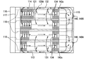
- FIG. 2 is a cross-sectional view showing a II-II portion in FIG. 1.
- FIG. 3 is a cross-sectional view showing a III-III portion in FIG. 1.
- FIG. 4 is a cross-sectional view showing a IV-IV part in FIG. 1.
- It is a disassembled perspective view which shows an internal fin.
- It is a perspective view which shows an external fin.
- It is a perspective view which shows an external duct.
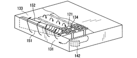
- It is a perspective view which shows the flow of the cooling fluid in an external duct.
- a battery pack 100 according to a first embodiment which is an example of the present invention will be described with reference to FIGS.
- the battery pack 100 is used, for example, in a hybrid vehicle using a motor driven by electric power charged in a battery and an internal combustion engine as a travel drive source, or an electric vehicle using a motor as a travel drive source.
- the plurality of battery cells 121 included in the battery pack 100 are, for example, a nickel hydrogen secondary battery, a lithium ion secondary battery, an organic radical battery, or the like.
- the battery pack 100 is installed in a pack accommodation space such as a trunk room of the vehicle or a back area of the trunk room provided below the trunk room.
- This pack storage space can also store spare tires, tools, and the like, for example.
- the battery pack 100 is installed in the pack accommodation space with the bottom wall 112 and the bottom wall side passage 135 positioned downward.
- the battery pack 100 may be installed below a front seat or a rear seat provided in a vehicle cabin.
- the battery pack 100 is installed below the front seat, the rear seat, etc. with the bottom wall 112 and the bottom wall side passage 135 positioned downward.
- the space where the battery pack 100 is installed below the rear seat may be communicated with the trunk room back area below the trunk room.
- the installation space can also be configured to communicate with the outside of the vehicle.
- the battery pack 100 includes a case 110 that forms a sealed internal space isolated from the outside, an assembled battery 120 (cell stack 120A) that includes a plurality of battery cells 121 that are connected to be energized, and heat that is formed in the case 110.
- a circulation passage 130 through which a replacement fluid flows, and a blower 140 that circulates the fluid in the circulation passage 130 are provided.
- internal fins 150 (151 and 152) are provided inside the case 110, and external fins 160 (161 and 162) are provided outside the case 110 (FIGS. 5 and 6).
- external fins 160 (161 and 162) are provided outside the case 110 (FIGS. 5 and 6).
- an external duct 170 having a blower 172 is provided outside the external fin 160 (FIG. 7).
- Fr indicates the vehicle front side
- Rr indicates the vehicle rear side
- RH indicates the vehicle right side
- LH indicates the vehicle left side.
- the Fr-Rr direction is referred to as the front-rear direction
- the RH-LH direction is referred to as the left-right direction
- the action direction of gravity is referred to as the vertical direction.
- the case 110 is a housing that houses the assembled battery 120 and the blower 140 (140A, 140B).
- the case 110 has a box shape composed of a plurality of walls surrounding an internal space, and is formed of a molded product of an aluminum plate or an iron plate.
- the case 110 is, for example, a rectangular parallelepiped that is flat in the vertical direction, and has six surfaces, that is, the top wall 111, the bottom wall 112, the first side wall 113, the second side wall 114, the third side wall 115, and the fourth side wall 116. have.
- the case 110 also has a partition wall 117 that partitions the inside, and a reinforcing beam 118 on the bottom wall 112.
- the top wall 111 is a wall that forms the upper surface of the case 110, and is a rectangular wall having long sides in the front-rear direction.
- the bottom wall 112 is a wall that forms the lower surface of the case 110 and has the same shape as the top wall 111.
- the first and second side walls 113 and 114 are walls that form the left and right sides of the case 110, and are elongated rectangular walls having long sides in the front-rear direction.
- the first and second side walls 113 and 114 are in a positional relationship facing each other.
- the third and fourth side walls 115 and 116 are walls that form the front and rear sides of the case 110, and are elongated rectangular walls having long sides in the left-right direction.
- the third and fourth side walls 115 and 116 are in a positional relationship facing each other.
- the third and fourth side walls 115 and 116 are walls orthogonal to the first and second side walls 113 and 114.
- the case 110 may be manufactured by forming a box-shaped space inside by joining and assembling a plurality of case bodies instead of using the walls 111 to 116 described above. Moreover, you may make it form a some convex part or a recessed part in the surface of a predetermined wall among the several walls of case 110, in order to enlarge a thermal radiation area.
- the direction along the long sides of the first and second side walls 113, 114 corresponds to the front-rear direction
- the direction along the long sides of the third and fourth side walls 115, 116 is left and right. It corresponds to the direction.
- the partition wall 117 is disposed on the fourth side wall 116 side inside the case 110 and is a wall that connects the first and second side walls 113 and 114 in parallel with the fourth side wall 116.
- the partition wall 117 extends from the upper surface of the bottom wall 112 (the surface on the inner side of the case 110) to an intermediate position in the vertical direction of the case 110.
- a space 117 a is formed between the partition wall 117 and the fourth side wall 116. For example, a battery management unit is accommodated in the space 117a.
- the battery management unit (Battery Management Unit) is configured to be able to communicate with various electronic control devices mounted on the vehicle.
- the battery management unit is a device that manages at least the amount of electricity stored in the battery cell 121, and is an example of a battery control unit that performs control related to the battery cell 121. Further, the battery management unit may be a device that monitors current, voltage, temperature, and the like related to the battery cell 121 and manages an abnormal state of the battery cell 121, electric leakage, and the like.
- a signal related to the current value detected by the current sensor is input to the battery management unit.
- the battery management unit includes an input circuit, a microcomputer, an output circuit, and the like. Battery information is stored as data in the storage means of the microcomputer.
- the stored battery information data includes, for example, the battery voltage, the charging current, the discharging current, and the battery temperature in the battery pack 100.
- the battery management unit also functions as a control device that controls the operations of the fans 140A and 140B, the fan 172, and the PTC heater 144. Temperature information detected by a temperature detector that detects the temperature of the battery cell 121 is input to the battery management unit.
- the temperature detector is provided in each battery cell 121 or a predetermined battery cell 121 in the plurality of battery cells 121.
- the temperature detector can be configured by a temperature detection line, a temperature sensor, or the like that outputs a signal to the battery management unit.
- the battery management unit operates each of the fans 140A and 140B, the fan 172, and the PTC heater 144 when a condition for performing battery cooling or battery heating according to the battery temperature detected by the temperature detector is established. Control.
- the beam 118 is a reinforcing member for improving the strength of the case 110, and is in parallel with the upper surface of the bottom wall 112 (the surface on the inner side of the case 110). A plurality are provided. In the present embodiment, five beams 118 are set.
- the beam 118 is formed in an elongated bar shape, and is provided on the bottom wall 112 so that the longitudinal direction thereof faces the front-rear direction with respect to the case 110 and is arranged at equal intervals in the left-right direction.
- the beam 118 is formed separately from the case 110 and is, for example, a prismatic member that is hollow and has a square cross section. More specifically, the beam 118 has a U-shaped cross-section (or rectangular bracket shape), and the U-shaped opening side is fixed to the bottom wall 112.
- the beam 118 is made of, for example, an aluminum material or an iron material.
- the two beams 118 are arranged along (contact with) the first and second side walls 113 and 114, respectively. Further, the remaining three beams 118 are arranged between the two beams 118. The intervals between the five beams 118 are equal.
- the pitch (distance between center lines) between the beams 118 is set to be equal to the horizontal dimension of the battery cell 121.
- the dimension between the adjacent beams 118 among the plurality of beams 118 is set to be larger than the width dimension of one beam 118.
- the width dimension of the beam 118 is a dimension in a direction in which the beams 118 are arranged.
- the plate thickness of the beam 118 is set to be thicker than the plate thickness of the bottom wall 112.
- the length of the beam 118 is set to be longer than the length in the direction along the beam 118 in the plurality of battery cells 121 as a whole. That is, the longitudinal dimension of the beam 118 is set to be longer than the dimension in the stacking direction of the cell stack 120 ⁇ / b> A formed by the plurality of battery cells 121.
- a plate-shaped blocking wall 119 a connected from the first side wall 113 to the second side wall 114 is provided on the upper surface of the plurality of beams 118. Yes. The upper side of the space between the beams 118 is blocked by the blocking wall 119a.
- a plate-shaped blocking wall 119b connected from the first side wall 113 to the second side wall 114 is formed on the upper surface of the plurality of beams 118. Is provided. The upper side of the space between the beams 118 is blocked by the blocking wall 119b.
- the assembled battery 120 is formed by providing a plurality of cell stacks 120A in which a plurality of battery cells 121 are stacked.
- one cell stack 120A is formed by 20 battery cells 121, and four cell stacks 120A are arranged to form an assembled battery 120 (see FIG. 1).
- the battery cell 121 has a rectangular parallelepiped shape that is flat in the front-rear direction, and includes a positive electrode terminal and a negative electrode terminal that protrude outward from the outer case.
- the battery cell 121 corresponds to the battery of the present invention.
- the cell stack 120A is formed by stacking a plurality of battery cells 121 and accommodating the stacked battery cells 121 in a battery case. That is, the plurality of battery cells 121 are stacked such that the surfaces perpendicular to the flat direction face each other.
- the battery case is a case in which the upper surface side and the lower surface side of each battery cell 121 are opened to cover the periphery of each battery cell 121.
- the cell stack 120A corresponds to the stack of the present invention.
- terminals of different polarities in adjacent battery cells 121 are electrically connected by a conductive member such as a bus bar.
- the connection between the bus bar and the electrode terminal is performed, for example, by screwing or welding. Therefore, the total terminal portions arranged at both ends of the plurality of battery cells 121 electrically connected by a bus bar or the like are supplied with electric power from the outside or discharged toward other electric devices. Yes.
- a predetermined gap is provided between the plurality of battery cells 121 to be stacked.
- This gap is formed by a spacer member or the like provided between the battery cells 121.
- the spacer member can be formed and provided by providing a partition wall portion between the battery cells 121 and providing unevenness or the like on the partition wall portion.
- the plurality of cell stacks 120 ⁇ / b> A are fixed (arranged) on the upper surface of the beam 118. Specifically, in each cell stack 120A (each battery cell 121), both lower ends of the direction in which the plurality of beams 118 are arranged (left and right direction) are placed on the two beams 118, respectively. Is placed (fixed).
- the first cell stack 120A out of the four cell stacks 120A is placed on the first and second beams 118 as viewed from the first side wall 113 side. It has been.
- the second cell stack 120A is placed on the second and third beams 118 as viewed from the first side wall 113 side.
- the third cell stack 120A is placed on the third and fourth beams 118 when viewed from the first side wall 113 side.
- the fourth cell stack 120A is placed on the fourth and fifth beams 118 as viewed from the first side wall 113 side.
- the circulation passage 130 is a passage formed in the case 110 and through which a fluid for heat exchange flows around each battery cell 121.
- the circulation passage 130 mainly includes a first side wall passage 131, a second side wall passage 132, and a ceiling wall.
- a side passage 133, a battery passage 134, a bottom wall side passage 135, and a series of flow passages connecting the fans 140A and 140B are formed.
- the first side wall-side passage 131 is orthogonal to both the top wall 111 and the bottom wall 112, extends in parallel to the first side wall 113, and includes a plurality of battery cells 121 (the assembled battery 120) and the first side wall 113. A passage formed between them.
- the second side wall-side passage 132 is orthogonal to both the top wall 111 and the bottom wall 112, extends in parallel to the second side wall 114, and includes a plurality of battery cells 121 (the assembled battery 120) and the second side wall 114. A passage formed between them.
- the top wall side passage 133 is a passage formed between the top wall 111 and the plurality of battery cells 121 (the assembled battery 120) and extending in parallel to the top wall 111.
- the first side wall side passage 131 and the top wall side passage 133 are connected at the boundary between the top wall 111 and the first side wall 113.
- the second side wall passage 132 and the top wall side passage 133 are connected at the boundary between the top wall 111 and the second side wall 114.
- the battery passage 134 is a passage formed by a gap between adjacent battery cells 121 in each cell stack 120A.
- the bottom wall side passage 135 is a passage formed as a space surrounded by the bottom wall 112, the lower end surfaces 121 a of the plurality of battery cells 121, and the beam 118.
- the bottom wall side passage 135 includes a space surrounded by the bottom wall 112, the blocking wall 119a, and the beam 118, and further includes a space surrounded by the bottom wall 112, the blocking wall 119b, and the beam 118.
- the bottom wall side passage 135 is a passage formed between the adjacent beams 118 on the lower side of each battery cell 121. In the present embodiment, four passages are formed based on the five beams 118. It is formed as.
- the second passage from the first side wall 113 side communicates with the first passage by a communication portion (not shown) in the vicinity of the blower 140A. Further, the third passage from the first side wall 113 side communicates with the fourth passage by a communication portion (not shown) in the vicinity of the blower 140B.
- the upper side of the battery passage 134 is connected to the top wall side passage 133, and the lower side of the battery passage 134 is connected to the bottom wall side passage 135.
- the blower 140 is a fluid driving means that is housed in the case 110 and forcibly circulates (circulates) the heat exchange fluid in the circulation passage 130.
- the blower 140 is set so that two of the first blower 140A and the second blower 140B are arranged.
- the two blowers 140A and 140B may be collectively referred to as the blower 140.
- the fluid circulated in the circulation passage 130 for example, air, various gases, water, a refrigerant, or the like can be used.
- the first blower 140 ⁇ / b> A is a blower that circulates fluid through the circulation passage 130 corresponding to the region of the two cell stacks 120 ⁇ / b> A on the first side wall 113 side.
- the second blower 140B is a blower that circulates fluid through the circulation passage 130 corresponding to the region of the two cell stacks 120A on the second side wall 114 side.
- the first blower 140A and the second blower 140B are symmetrical with respect to the center line facing the front-rear direction of the case 110, and the third side wall 115 and the cell stack 120A (a plurality of battery cells 121). ).
- Each blower 140A, 140B has a motor 141, a sirocco fan 142, and a fan casing 143.
- the motor 141 is an electric device that rotationally drives the sirocco fan 142, and is provided on the upper side of the sirocco fan 142.
- the sirocco fan 142 is a centrifugal fan that sucks fluid in the direction of the rotation axis and blows out fluid in the centrifugal direction.
- the sirocco fan 142 is arranged so that its rotation axis is directed in the vertical direction.
- the fan casing 143 is formed so as to cover the sirocco fan 142, and serves as an air guide member that sets the suction and blowing directions of the fluid by the sirocco fan 142.
- the fan casing 143 has a suction port 143a that opens below the sirocco fan 142, a blowout duct 143b that guides the flow of the blown fluid, and a blowout port 143c that opens at the tip of the blowout duct 143b.
- the air inlets 143a of the fans 140A and 140B are arranged so as to be connected to the region on the third side wall 115 side in the bottom wall side passage 135.
- the suction port 143a of the blower 140A is connected to the first and second passages from the first side wall 113 side among the four bottom wall side passages 135.
- the suction port 143a of the blower 140B is connected to the third and fourth passages from the first side wall 113 side among the four bottom wall passages 135.
- Each blower duct 143b of each blower 140A, 140B extends from the side surface of the sirocco fan 142 to the center side of the case 110 once. And each blowing duct 143b is formed to extend to the first and second side wall passages 131 and 132, respectively, so as to make a U-turn.
- the blower outlet 143c of the air blower 140A is arrange
- the air outlet 143c is located near the battery cell 121 on the third side wall 115 side among the plurality of battery cells 121 stacked at a position closer to the lower side in the vertical direction in the first side wall side passage 131. And, it is arranged so as to face the fourth side wall 116 side.
- the air outlet 143c of the blower 140B is arranged so as to be connected to the second side wall side passage 132. Specifically, the air outlet 143c is located near the battery cell 121 on the third side wall 115 side among the plurality of battery cells 121 stacked at the lower side in the vertical direction of the second side wall passage 132. And, it is arranged so as to face the fourth side wall 116 side.
- a heating device for heating the fluid to a predetermined temperature is provided.
- a PTC heater 144 having a self-temperature control function is used.
- the internal fin 150 is a heat exchange promoting fin provided inside the case 110, and includes a first internal fin 151 and a second internal fin 152.
- Each of the internal fins 151 and 152 is formed of an aluminum material or an iron material having excellent thermal conductivity.
- the first internal fins 151 are provided on the first side wall 113 side and the second side wall 114 side so as to be symmetric with respect to the center line facing the front-rear direction of the case 110.
- the second internal fins 152 are provided at two locations on the first side wall 113 side and the second side wall 114 side of the top wall 111 so as to be symmetric with respect to the center line facing the front-rear direction of the case 110. ing.
- each of the internal fins 151 and 152 for example, a straight fin capable of setting a flow resistance to a fluid relatively small is employed.
- the straight fins are fins in which a large number of thin plate-like fin portions protruding vertically from the thin plate-like substrate portion are arranged in parallel, and fluid passages are formed between the fin portions.
- the internal fins 151 and 152 are not limited to the straight fins, but may be other corrugated fins (with or without louvers), offset fins, or the like.
- the substrate portion of the first internal fin 151 has long and narrow right triangles A, B, and C, and the angles ABC are almost perpendicular.
- the length of the long side AB extending in the front-rear direction is set to be equal to the length in the stacking direction of the cell stack 120A.
- the length of the short side BC extending in the vertical direction is set to be slightly smaller than the vertical dimension of the first and second side walls 113 and 114.
- the substrate part is arranged so that the position in the front-rear direction corresponds to the position of the cell stack 120A.
- the short side BC is located on the fourth side wall 116 side
- the apex angle BAC facing the short side BC is located on the third side wall 115 side
- the long side AB is It arrange
- the fin portion of the first internal fin 151 protrudes vertically from the substrate portion toward the plurality of battery cells 121, and the protruding tip portion has a plurality of batteries so that more fluid flows through the fin portion. It extends to a position close to the side surface of the cell 121. Further, the plate surface of the fin portion is set to be inclined toward the fourth side wall 116 from the lower side to the upper side with respect to the vertical direction. Further, the length of the fluid passage by the fin portion becomes longer as it goes from the third side wall 115 side to the fourth side wall 116 side.
- the substrate portion of the second internal fin 152 has elongated triangular shapes D, E, and F.
- the length of the long side DE extending in the front-rear direction is set to be equal to the long side AB of the substrate portion of the first internal fin 151.
- the substrate portion of the second internal fin 152 is disposed so that the position in the front-rear direction corresponds to the position of the first internal fin 151.
- the short side EF is located on the third side wall 115 side
- the apex angle EDF facing the short side EF is located on the fourth side wall 116 side
- the long side DE is the top side.
- the substrate portion of the second internal fin 152 is joined to the inner surface of the top wall 111 so as to be adjacent to the fin portion of the first internal fin 151. Yes.
- the fin portion of the second internal fin 152 protrudes vertically from the substrate portion toward the plurality of battery cells 121, and the protruding tip portion has a plurality of protrusions so that more fluid flows inside the fin portion.
- the battery cell 121 extends to a position close to the upper surface.
- the plate surface of the fin portion is set to be inclined toward the fourth side wall 116 toward the center side of the case 110 with respect to the left-right direction.
- the length of the fluid passage by the fin portion is shortened from the third side wall 115 side toward the fourth side wall 116 side.
- the fluid passage by the fin part of the 2nd internal fin 152 is connected so that the fluid path by the fin part of the 1st internal fin 151 may be followed.
- the external fin 160 is a heat exchange promoting fin provided on the outside of the case 110, and includes a first external fin 161 and a second external fin 162.
- Each external fin 161, 162 is formed of a material having excellent thermal conductivity, for example, an aluminum material or an iron material.
- the first external fins 161 are provided on the first side wall 113 side and the second side wall 114 side so as to be symmetric with respect to the center line facing the front-rear direction of the case 110.
- the second external fins 162 are provided at two locations on the first side wall 113 side and the second side wall 114 side of the top wall 111 so as to be symmetric with respect to the center line facing the front-rear direction of the case 110. ing.
- each external fin 161, 162 for example, a corrugated fin capable of setting a heat transfer performance for a fluid relatively large is employed.
- the corrugated fin has a wave shape as a whole, and a large number of louvers are formed on the wavy surfaces facing each other, and a fluid passage is formed between the wavy surfaces facing each other and between the louvers. It has become a fin.
- the external fins 161 and 162 may be straight fins such as the internal fins 151 and 152, corrugated fins without louvers, or offset fins.
- the first outer fins 161 are provided as a set of a plurality of (two in this case), and the first and second side walls 113 and 114 have a wave in a region corresponding to the first inner fin 151.
- the continuous direction is directed in the front-rear direction and is slightly offset toward the fourth side wall 116 side.
- the second external fins 162 are provided as a set of a plurality (two in this case) and correspond to the second internal fins 152 on the first and second side walls 113 and 114 side of the top wall 111. Within the region, the wave is arranged such that the direction in which the waves continue is directed in the front-rear direction and slightly closer to the third side wall 115 side than the first external fin 161.
- the external duct 170 is a duct that circulates a cooling fluid along the outer surface of the case 110 as shown in FIG. 7 (FIG. 11).
- a cooling fluid for example, cooled air in the passenger compartment is used.
- the outer duct 170 has a flat cross-sectional shape, and the outer surface of the case 110, specifically, the first and second side walls 113 and 114 region, the first and second side walls 113 and 114 side of the top wall 111. And the third sidewall 115 region, and are formed so as to enclose (cover) the external fins 161 and 162.
- the inside of the external duct 170 is mainly a flow path that connects the first and second side walls 113 and 114 region, the first and second side wall 113 and 114 side regions of the top wall 111, and the third side wall 115 region in this order. ing.
- Both ends of the external duct 170 on the fourth side wall 116 side are suction portions for sucking cooling air.
- a wind direction device 171 for diverting the sucked cooling air to the lower side of the first external fin 161 and the center side of the case 110 of the second external fin 162 is provided on the downstream side immediately after the suction portion. .
- a blower 172 is provided in the center of the external duct 170 on the third side wall 115 side, and the upper and lower portions of the blower 172 serve as blow-out portions for blowing cooling air.
- a turbo fan is used for the blower 172.
- Battery cell 121 self-heats at the time of output from which current is taken out and at the time of input to be charged. Further, the battery cell 121 is affected by the temperature outside the case 110 according to the season.
- the battery management unit constantly monitors the temperature of the battery cell 121 in the battery pack 100 with the temperature detector, and controls the operation of each of the fans 140A and 140B, the fan 172, and the PTC heater 144 based on the temperature of the battery cell 121. It is like that.
- the battery management unit applies a voltage to each of the blowers 140A and 140B according to the temperature of the battery cell 121 to operate the sirocco fan 142. Further, depending on the temperature of the battery cell 121, the PTC heater 144 may be operated together with the fans 140A and 140B, or the fan 172 may be operated together with the fans 140A and 140B.
- the fluid sucked from the suction ports 143a of the blowers 140A and 140B and blown from the blowout port 143c through the blowout duct 143b flows into the first side wall side passage 131 and the second side wall side passage 132, respectively. .
- the fluid flowing into the first and second side wall passages 131 and 132 flows from the lower side (the bottom wall 112 side) to the upper side (the top wall 111) along the inclined fin portions of the first internal fins 151. Flows smoothly toward the side.
- Each of the first and second side wall-side passages 131 and 132 is a flat cross-sectional passage that extends long along the long side of each of the first and second side wall-side passages 131 and 132, and is an inlet when fluid flows.
- the cross-sectional area is smaller than the other top wall side passage 133, battery passage 134, and bottom wall side passage 135, and a fluid flow rate can be obtained to some extent.
- dynamic pressure is a dominant field. . Therefore, in each of the first and second side wall passages 131 and 132, the heat of the fluid accompanied by the flow velocity is effectively transmitted to the first internal fin 151, and further externally through the first and second side walls 113 and 114. To be released.
- the fluid smoothly flows to the fin portion of the second internal fin 152 continuously connected to the first internal fin 151 and flows into the top wall side passage 133 along this fin portion.
- the inlet cross-sectional area when flowing into the top wall side is much larger than the inlet cross-sectional area when flowing into the first and second side wall passages 131 and 132, and the flow velocity of the fluid is small.
- Static pressure is the dominant field. Therefore, the fluid that has flowed into the top wall side passage 133 from the first and second side wall passages 131 and 132 side spreads evenly in the top wall side passage 133.
- the fluid flowing into the top wall side passage 133 from the first side wall side passage 131 mainly spreads in the region of the two cell stacks 120A on the first side wall 113 side.
- the fluid that has flowed into the top wall side passage 133 from the second side wall side passage 132 mainly extends to the region of the two cell stacks 120A on the second side wall 114 side.
- the heat of the fluid flowing into the ceiling wall side passage 133 is transmitted from the second internal fins 152 to the ceiling wall 111 or directly transmitted to the ceiling wall 111 and released to the outside.
- path 133 become positive pressure space by blowing of each air blower 140A, 140B, and the bottom wall side channel
- 140B is sucked into a negative pressure space, and the fluid is continuously moved from the top wall side passage 133 side to the bottom wall side passage 135 side by the pressure difference therebetween.
- the heat of each battery cell 121 is transmitted to the fluid.
- the fluid that has flowed into the bottom wall side passage 135 moves along the longitudinal direction of each beam 118 and reaches the suction port 143a of each of the fans 140A and 140B. Then, the heat of the fluid flowing into the bottom wall side passage 135 is transmitted to the bottom wall 112 and released to the outside.
- the fluid circulates through the circulation passage 130 in the case 110, so that the heat of the fluid, that is, the heat of the battery cell 121, is mainly released from the wide top wall 111 and bottom wall 112.
- the PTC heater 144 is operated in addition to the operations of the fans 140A and 140B. At this time, the fluid flowing through the blowout duct 143b is heated by the PTC heater 144. As the heated fluid circulates in the circulation passage 130 in the case 110 as described above, each battery cell 121 is heated to a temperature at which it can be properly operated by the heated fluid. The performance degradation at the time is corrected.
- the blower 172 in the external duct 170 is operated in addition to the operation of each of the blowers 140A and 140B. In this case, the cooling air in the passenger compartment is sucked into the external duct 170 from the suction portion of the external duct 170.
- the cooling air sucked from the suction port is diverted by the wind direction device 171 and is diverted toward the lower side of the first external fin 161 and the center side of the case 110 of the second external fin 162.
- the And each flow passes and merges so that each external fin 161,162 may be crossed, and it blows off from the blowing part provided in the upper and lower part of the air blower 172.
- the heat of the fluid in the case 110 is transmitted to the cooling air via the internal fins 151 and 152, the first and second side walls 113 and 114, the top wall 111, and the external fins 161 and 162. To be released. Therefore, heat exchange of the fluid in the case 110 is further promoted by the external fins 161 and 162 in addition to the internal fins 151 and 152.
- Each battery cell 121 is forcibly cooled to an appropriate temperature in a short time.
- the battery cell 121, the circulation passage 130, and the blowers 140A and 140B are provided in the case 110. Furthermore, by providing the PTC heater 144 and the internal fins 151 and 152, the temperature of each battery cell 121 can be adjusted according to the temperature of the battery cell 121 without leaking the operating sound of the fans 140 A and 140 B into the vehicle interior. It is possible to perform heating appropriately. Further, by providing the external fins 161 and 162 and the external duct 170 (blower 172), forced cooling at high temperatures can be performed.
- the beams 118 can be used as reinforcing members to increase the strength of the case 110. Since the plurality of battery cells 121 are arranged on the beam 118, even if an impact is applied from the outside of the case 110, the beam 118 is subjected to an impact. Can be protected from impact.
- the bottom wall side passage 135 forming a part of the circulation passage 130 is formed by utilizing the reinforcing beam 118. Since the width dimension of the bottom wall side passage 135 formed between the adjacent beams 118 is set to be larger than the width dimension of one beam 118, the bottom wall side passage 135 is set. Has a small flow resistance to the fluid, can be used as a passage through which the entire fluid flows effectively, and heat exchange by the fluid can be effectively performed.
- the beam 118 is used as a member for forming a part of the bottom wall side passage 135, the battery pack 100 itself is larger than the case where a beam is simply provided to reinforce the case 110. It will not become.
- the beam 118 is a hollow member formed separately from the bottom wall 112, and the plate thickness of the beam 118 is set to be thicker than the plate thickness of the bottom wall 112. Thereby, the reinforcement effect by the beam 118 can be raised.
- the plate thickness of the bottom wall 112 is set to be thinner than the plate thickness of the beam 118, the thermal resistance in the bottom wall 112 can be lowered, and the fluid exchanged with the battery cell 121 and the bottom wall 112. It is possible to increase the heat exchange efficiency with.
- the plurality of battery cells 121 form a cell stack 120A that is stacked in the longitudinal direction of the beam 118.
- the cell stack 120A is arranged in the same manner as the array of the beams 118. Are arranged such that the lower end portions in the direction in which the beams 118 are arranged are respectively placed on the beams 118. Accordingly, stable battery cells 121 can be installed on the beams 118, and the heat exchange area of the lower end surface 121a of each battery cell 121 can be made the bottom wall side passage 135 maximally active. it can.
- a gap is provided between the battery cells 121 in the stacking direction of the cell stack 120A, and this gap serves as a battery passage 134 that forms a part of the circulation passage 130.
- the battery passage 134 is a bottom wall side passage 135. Communicated with. Accordingly, it is possible to easily form the circulation passage 130 in which the battery passage 134 and the bottom wall side passage 135 are connected without using a connection member such as a duct.
- the beam 118 of the first embodiment is a hollow member used for the beam 118 of the first embodiment, a solid member may be used.
- the beam 118 is a separate member from the bottom wall 112, a shape corresponding to the beam 118 may be formed integrally with the bottom wall 112 by providing irregularities on the bottom wall 112.
- the plate thickness of the beam and the bottom wall 112 is the same.
- the length of the beam 118 can be at least equal to the dimension in the stacking direction of the cell stack 120A.
- each battery cell 121 is configured such that both ends in the direction in which the beams 118 are arranged are placed on the beam 118, but the dimension between the adjacent beams 118 is the width of one beam 118. If it is set to be larger than the dimension, the middle part of each battery cell 121 may be placed on the beam 118.
- the fluid in the case 110 flows through the circulation passage 130 in the order of the fans 140A and 140B, the first and second side wall passages 131 and 132, the top wall side passage 133, the battery passage 134, and the bottom wall side passage 135. Although it circulates, you may make it reverse.
- the battery pack 100 of the said 1st Embodiment was made to circulate a fluid to the circulation channel
- the fluid may be circulated through the circulation passage 130.
- an axial fan, a turbo fan, or the like can be used in addition to the sirocco fan described in the first embodiment.
- the PTC heater 144 is not limited to the inside of the fan casing 143 but may be provided inside the case 110 and outside the fan casing 143.
- the essential configuration of the present invention is the case 110, the assembled battery 120, the circulation passage 130, and the blower 140, and the internal fin 150, the external fin 160, and the external duct 170 may be set as necessary. .
- fins integrally formed on the first and second side walls 113 and 114 and the top wall 111 may be used.
- the case (housing) 110 forms a hexahedron and a rectangular parallelepiped, but the housing included in the invention is not limited to this shape.
- the case 110 may be a polyhedron having more than six surfaces, or at least one surface may include a curved surface.
- the case 110 may be formed in a dome shape in which the top wall 111 includes a curved surface, or the case 110 may have a trapezoidal vertical cross-sectional shape.
- the top wall 111 is a wall having a positional relationship facing the bottom wall 112, and the shape thereof may include either a flat surface or a curved surface.
- the first side wall 113 to the fourth side wall 116 may be walls extending from the bottom wall 112 in a direction intersecting the bottom wall 112, or the top side wall in the direction intersecting the top wall 111.
- a wall extending from the wall 111 may be used.
- the boundary portion between the top wall 111 and the first side wall 113 to the fourth side wall 116 in the case 110 may form a corner or a curved surface.
- the boundary between the bottom wall 112 and the first side wall 113 to the fourth side wall 116 in the case 110 may form a corner or may form a curved surface.
- the cell stack 120A included in the battery pack 100 is four, but the number is not limited to this. That is, when only one cell stack 120A included in the battery pack 100 is accommodated inside the case 110, or when a plurality of cell stacks 120A are installed side by side in one direction, the cell stack 120A is arranged in another direction that intersects the one direction. This also includes the case where a plurality are installed side by side.
- Battery pack 110 Case (housing) 112 Bottom wall 118 Beam 120A Cell laminate (laminate) 121 Battery cell (battery) 121a Lower end surface 130 Circulation passage 134 Battery passage 135 Bottom wall side passage 140 Blower
Landscapes
- Chemical & Material Sciences (AREA)
- Chemical Kinetics & Catalysis (AREA)
- Electrochemistry (AREA)
- General Chemical & Material Sciences (AREA)
- Engineering & Computer Science (AREA)
- Manufacturing & Machinery (AREA)
- Secondary Cells (AREA)
- Battery Mounting, Suspending (AREA)
Abstract
複数の電池121と、筐体110と、循環通路130と、送風機140と、を備える電池パックにおいて、循環通路130は、電池121の下端面121aと、筐体110の底部側となる底壁112との間に形成される底壁側通路135を含んでいる。底壁112には、筐体110に対する補強用の梁118が複数並ぶように設けられ、梁118の上に電池121が配置されている。底壁側通路135は、電池121の下端面121a、底壁112、および梁118によって囲まれた空間として形成され、隣り合う梁118と梁118との間に形成される底壁側通路135の幅寸法は、1つの梁118の幅寸法よりも大きくなるように設定されている。
Description
本発明は、ケース内部に収容された複数個の電池セルを有する電池パックに関するものである。
従来、電池セルを有する電池パックとして、例えば、特許文献1に記載されたものが知られている。特許文献1(電池冷却装置)に記載の電池パックは、複数の電池セルと、複数の電池セルを収容する筐体と、筐体内において複数の電池セルと熱交換(冷却)する流体が流通する循環通路と、循環通路に流体を循環させる送風機とを備えている。
上記循環通路には、複数の電池セルと熱交換した後の流体が集合されて、送風機に向かって同一方向に流れる集合通路が設けられている。集合通路は、例えば、複数の電池セル間における電池通路の下側と連通すると共に、送風機の流入通路に接続される集合ダクトとして形成されている。特許文献1では、このような集合通路によって、電池セルと熱交換した後の流体を集合させて流速を確保することで、電池セルの効果的な熱交換(冷却)を可能としている。
ところで、電池パックにおける複数の電池セルは、所定の電気機器に対する電力の供給、あるいは充電装置による充電を行うための重要な部品であり、例えば、車両に搭載された場合に衝突等の衝撃があったとしても、電池セルを衝撃から守ることができるような配慮が必要となる。しかしながら、上記特許文献1では、良好な熱交換性能を備えているものの、電池セルを衝撃から保護するための配慮はなされていない。
本発明は、上記問題点に鑑みてなされたものであり、複数の電池に対する良好な熱交換性能を備えると共に、衝撃時の電池の保護を可能とする電池パックを提供することを目的とする。
本発明は上記目的を達成するために、以下の技術的手段を採用する。
開示される一つの態様は、複数の電池と、複数の電池を収容する筐体と、筐体内に形成されて、電池の周りを熱交換用の流体が流通する循環通路と、循環通路に流体を流通させる送風機と、を備える電池パックであって、循環通路は、電池の下端面と、筐体の底部側となる底壁との間に形成される底壁側通路を含んでおり、底壁には、筐体に対する補強用の梁が並列となるように複数設けられ、梁の上に電池が配置されており、底壁側通路は、電池の下端面、底壁、および梁によって囲まれた空間として形成され、隣り合う梁と梁との間に形成される底壁側通路の幅寸法は、1つの梁の幅寸法よりも大きくなるように設定されていることを特徴としている。
この本発明によれば、筐体の底壁には複数の梁が設けられているので、この梁が補強部材となって筐体の強度を上げることができる。そして、複数の電池は、梁の上に配置されているので、仮に、筐体の外部から衝撃が加わった場合でも、梁が衝撃を受ける形となるので、複数の電池を衝撃から保護することができる。
また、循環通路の一部を成す底壁側通路は、上記補強用の梁を活用して形成されている。そして、隣り合う梁と梁との間に形成される底壁側通路の幅寸法は、1つの梁の幅寸法よりも大きくなるように設定されているので、底壁側通路は、流体に対する流通抵抗が小さく、流体の全体を効果的に流す通路とすることができ、流体による熱交換を効果的に行うことが可能となる。
よって、複数の電池に対する良好な熱交換性能を備えると共に、衝撃時の電池の保護を可能とする電池パックとすることができる。
尚、特許請求の範囲における括弧内の符号は、記載内容の理解を容易にすべく、後述する実施形態において対応する構成を例示するものに留まり、発明の内容を限定することを意図したものではない。
以下に、図面を参照しながら本発明を実施するための複数の形態を説明する。各形態において先行する形態で説明した事項に対応する部分には同一の参照符号を付して重複する説明を省略する場合がある。各形態において構成の一部のみを説明している場合は、構成の他の部分については先行して説明した他の形態を適用することができる。各実施形態で具体的に組み合わせが可能であることを明示している部分同士の組み合わせばかりではなく、特に組み合わせに支障が生じなければ、明示していなくても実施形態同士を部分的に組み合せることも可能である。
(第1実施形態)
本発明の一例である第1実施形態の電池パック100について、図1~図7を参照しながら説明する。電池パック100は、例えば、電池に充電された電力によって駆動されるモータと、内燃機関とを走行駆動源とするハイブリッド自動車、あるいはモータを走行駆動源とする電気自動車等に用いられる。電池パック100に含まれる複数の電池セル121は、例えば、ニッケル水素二次電池、リチウムイオン二次電池、有機ラジカル電池等である。
本発明の一例である第1実施形態の電池パック100について、図1~図7を参照しながら説明する。電池パック100は、例えば、電池に充電された電力によって駆動されるモータと、内燃機関とを走行駆動源とするハイブリッド自動車、あるいはモータを走行駆動源とする電気自動車等に用いられる。電池パック100に含まれる複数の電池セル121は、例えば、ニッケル水素二次電池、リチウムイオン二次電池、有機ラジカル電池等である。
電池パック100は、車両のトランクルーム、あるいはトランクルームより下方に設けられたトランクルーム裏エリア等のパック収容スペースに設置される。このパック収容スペースは、例えば、スペアタイヤ、工具等も収納することができる。電池パック100は、底壁112や底壁側通路135を下側にした姿勢で、パック収容スペースに設置される。
また、電池パック100は、車両の車室内に設けられる前部座席の下方や後部座席等の下方に設置されるようにしてもよい。この場合、電池パック100は、底壁112や底壁側通路135を下側にした姿勢で、前部座席や後部座席等の下方に設置される。また、後部座席の下方において電池パック100を設置する空間は、トランクルームよりも下方のトランクルーム裏エリアに連通させるようにしてもよい。また当該設置空間は、車外に連通するようにも構成できる。
電池パック100は、外部と隔離した密閉された内部空間を形成するケース110、通電可能に接続される複数の電池セル121からなる組電池120(セル積層体120A)、ケース110内に形成され熱交換用の流体が流通する循環通路130、およびこの循環通路130に流体を循環させる送風機140等を備えている。
また、本電池パック100においては、ケース110の内側に、内部フィン150(151、152)が、またケース110の外側に外部フィン160(161、162)が設けられている(図5、図6)。更に、外部フィン160の外側には、送風機172を有する外部ダクト170が設けられている(図7)。
尚、本実施形態では、図1において、Frは車両前方側を示し、Rrは車両後方側を示し、RHは車両右側を示し、LHは車両左側を示している。電池パック100における方向を示す際に、Fr-Rrの方向を前後方向、RH-LHの方向を左右方向と呼ぶことにする。また、重力の作用方向を上下方向と呼ぶことにする。
ケース110は、組電池120、および送風機140(140A、140B)を内部に収容する筐体である。ケース110は、内部の空間を包囲する複数の壁からなる箱形を呈し、アルミニウム板または鉄板の成型品で形成されている。ケース110は、例えば、上下方向に扁平な直方体となっており、6面、即ち、天壁111、底壁112、第一側壁113、第二側壁114、第三側壁115、および第四側壁116を有している。また、ケース110は、内部を区画する区画壁117、および底壁112における補強用の梁118を有している。
天壁111は、ケース110の上側の面を形成する壁であり、前後方向に長辺を有する長方形の壁となっている。底壁112は、ケース110の下側の面を形成する壁であり、天壁111と同様の形状を有している。
また、第一および第二側壁113、114は、ケース110の左右側の面を形成する壁であり、前後方向に長辺を有する細長い長方形の壁となっている。第一および第二側壁113、114は、互いに向かい合う位置関係にある。また、第三および第四側壁115、116は、ケース110の前後側の面を形成する壁であり、左右方向に長辺を有する細長い長方形の壁となっている。第三および第四側壁115、116は、互いに向かい合う位置関係にある。また、第三および第四側壁115、116は、第一および第二側壁113、114に対して直交する壁となっている。
ケース110は、上記各壁111~116を用いたものに代えて、複数のケース体を接合して組み立てることにより、内部に箱体状の空間を形成して製作するようにしてもよい。また、ケース110の複数の壁のうち、所定の壁の表面には、放熱面積を大きくするために複数の凸部または凹部を形成するようにしてもよい。
尚、電池パック100において、第一および第二側壁113、114の長辺に沿う方向が前後方向に対応しており、また、第三および第四側壁115、116の長辺に沿う方向が左右方向に対応している。
区画壁117は、ケース110の内部において、第四側壁116側に配置されて、第四側壁116と平行となって、第一および第二側壁113、114間を繋ぐ壁となっている。区画壁117は、底壁112の上側の面(ケース110の内側となる面)からケース110の上下方向の中間位置まで延びている。区画壁117と第四側壁116との間には空間117aが形成されている。空間117aには、例えば、電池管理ユニットが収容されている。
電池管理ユニット(Battery Management Unit)は、車両に搭載された各種の電子制御装置と通信可能に構成されている。電池管理ユニットは、少なくとも電池セル121の蓄電量を管理する機器であり、電池セル121に係る制御を行う電池制御ユニットの一例である。また、電池管理ユニットは、電池セル121に関する電流、電圧、温度等を監視すると共に、電池セル121の異常状態、漏電等を管理する機器であってもよい。
また、電池管理ユニットには、電流センサによって検出された電流値に係る信号が入力される。電池管理ユニットは、車両ECUと同様に入力回路、マイクロコンピュータ、および出力回路等を備えている。マイクロコンピュータが有する記憶手段には、電池情報がデータとして随時蓄積されている。蓄積される電池情報のデータは、例えば、電池パック100における電池電圧、充電電流、放電電流、および電池温度等である。
また、電池管理ユニットは、各送風機140A、140B、送風機172、およびPTCヒータ144の作動を制御する制御装置としても機能するようになっている。電池管理ユニットには、電池セル121の温度を検出する温度検出器によって検出された温度情報が入力される。温度検出器は、複数の電池セル121において、各電池セル121または所定の電池セル121に設けられている。温度検出器は、電池管理ユニットに対して信号を出力する温度検出線、温度センサ等によって構成することができる。
電池管理ユニットは、温度検出器によって検出される電池温度に応じて電池冷却、あるいは電池加熱を実施する条件が成立した場合には、各送風機140A、140B、送風機172、およびPTCヒータ144の作動を制御する。
梁118は、図1~図3に示すように、ケース110の強度を向上させるための補強部材となっており、底壁112の上側の面(ケース110の内側となる面)に並列となるように複数本、設けられている。本実施形態では、梁118は、5本の設定となっている。梁118は、細長の棒状を成しており、長手方向がケース110に対して前後方向を向くように、且つ、左右方向に等間隔で並ぶようにして、底壁112に設けられている。
梁118は、ケース110に対して別体形成されたものであり、例えば、中空で断面が四角形を成す角柱部材となっている。更に具体的には、梁118は、断面形状がコの字状(あるいは矩形ブラケット状)を成しており、コの字状の開口側が底壁112に固定されている。梁118は、例えば、アルミニウム材、あるいは鉄材等から形成されている。
5本の梁118のうち、2本の梁118は、それぞれ、第一および第二側壁113、114に沿うように(当接するように)配置されている。また、残りの3本の梁118は、2本の梁118の間に配置されている。そして、5本の梁118の間隔は、等間隔となっている。各梁118同士のピッチ(中心線間距離)は、電池セル121の左右方向の寸法と同等となるように設定されている。そして、複数本の梁118のうち、隣り合う梁118間の寸法は、1つの梁118の幅寸法よりも大きくなるように設定されている。梁118の幅寸法とは、梁118が並べられる方向の寸法である。また、梁118の板厚は、底壁112の板厚よりも厚くなるように設定されている。
梁118の長手方向の一端側は、区画壁117に当接しており、また、梁118の長手方向の他端側は、第三側壁115に当接している。梁118の長さは、複数の電池セル121全体における梁118に沿う方向の長さよりも長くなるように設定されている。つまり、梁118の長手方向寸法は、複数の電池セル121によって形成されるセル積層体120Aの積層方向寸法よりも長くなるように設定されている。
区画壁117と複数の電池セル121(組電池120)との間において、複数本の梁118の上面には、第一側壁113から第二側壁114に繋がる板状の閉塞壁119aが設けられている。この閉塞壁119aによって、各梁118間の空間の上側は、閉塞されている。
同様に、第三側壁115と複数の電池セル121(組電池120)との間において、複数本の梁118の上面には、第一側壁113から第二側壁114に繋がる板状の閉塞壁119bが設けられている。この閉塞壁119bによって、各梁118間の空間の上側は、閉塞されている。
組電池120は、複数の電池セル121が積層されたセル積層体120Aが、複数設けられて形成されている。本実施形態では、例えば、20個の電池セル121によって1つのセル積層体120Aが形成され、このセル積層体120Aが4つ並べられて、組電池120が形成されている(図1参照)。
電池セル121は、前後方向に扁平な直方体を成しており、外装ケースから外部に突出する正極端子、および負極端子を備えている。電池セル121は、本発明の電池に対応する。
セル積層体120Aは、複数の電池セル121が積層されて、この積層された電池セル121が電池ケースに収容されて形成されている。即ち、複数の電池セル121は、扁平方向と直交する面が互いに向かい合うように積層されている。そして、電池ケースは、各電池セル121の上面側、および下面側が開口されて、各電池セル121の周囲を覆うケースとなっている。セル積層体120Aは、本発明の積層体に対応する。
セル積層体120Aにおいて、隣り合う電池セル121における異極の端子間は、バスバー等の導電部材によって電気的に接続されている。バスバーと電極端子との接続は、例えばネジ締めや、溶接等により行われる。したがって、バスバー等によって電気的に接続された複数の電池セル121の両端に配された総端子部は、外部から電力が供給されたり、他の電気機器へ向けて放電したりするようになっている。
また、セル積層体120Aにおいて、積層される複数の電池セル121の間には、それぞれ所定の隙間が形成されるように設置されている。この隙間は、電池セル121間に設けられたスペーサ部材等によって形成されている。スペーサ部材は、例えば、電池ケースにおいて、各電池セル121間に仕切り壁部を設け、この仕切り壁部に凹凸等を設けることで形成対応することができる。
複数のセル積層体120A(各電池セル121)は、梁118の上面に固定(配置)されている。具体的には、1つのセル積層体120A(各電池セル121)は、複数の梁118が並べられた方向(左右方向)の下側の両端部が、それぞれ2本の梁118の上に乗せられて配置(固定)されている。
つまり、図1、図3に示すように、4つのセル積層体120Aのうち、1つめのセル積層体120Aは、第一側壁113側から見て1本目と2本目の梁118の上に乗せられている。2つめのセル積層体120Aは、第一側壁113側から見て、2本目と3本目の梁118の上に乗せられている。3つめのセル積層体120Aは、第一側壁113側から見て、3本目と4本目の梁118の上に乗せられている。4つめのセル積層体120Aは、第一側壁113側から見て、4本目と5本目の梁118の上に乗せられている。
循環通路130は、ケース110内に形成され、各電池セル121の周りを熱交換用の流体が流通する通路であり、主に、第一側壁側通路131、第二側壁側通路132、天壁側通路133、電池通路134、底壁側通路135、および各送風機140A、140Bを結ぶ一連の流通路によって形成されている。
第一側壁側通路131は、天壁111、および底壁112の両方に直交し、第一側壁113に対して平行に延び、複数の電池セル121(組電池120)と第一側壁113との間に形成される通路である。
第二側壁側通路132は、天壁111、および底壁112の両方に直交し、第二側壁114に対して平行に延び、複数の電池セル121(組電池120)と第二側壁114との間に形成される通路である。
天壁側通路133は、天壁111と複数の電池セル121(組電池120)との間に形成されて、天壁111に平行に延びる通路である。
第一側壁側通路131と天壁側通路133は、天壁111と第一側壁113との境界部で繋がっている。また、第二側壁側通路132と天壁側通路133は、天壁111と第二側壁114との境界部で繋がっている。
電池通路134は、各セル積層体120Aにおいて、隣り合う電池セル121間の隙間によって形成される通路である。
底壁側通路135は、底壁112、複数の電池セル121の下端面121a、および梁118によって囲まれた空間として形成される通路である。加えて、底壁側通路135には、底壁112、閉塞壁119a、および梁118によって囲まれた空間、更には、底壁112、閉塞壁119b、および梁118によって囲まれた空間も含まれている。底壁側通路135は、各電池セル121の下側で、隣り合う梁118の間に形成される通路となっており、本実施形態では、5本の梁118をもとに、4つの通路として形成されている。
4つの底壁側通路135のうち、第一側壁113側から2つめの通路は、送風機140Aの近傍で、図示しない連通部によって1つめの通路と連通している。また、第一側壁113側から3つめの通路は、送風機140Bの近傍で、図示しない連通部によって4つめの通路と連通している。
電池通路134の上側は、天壁側通路133と繋がっており、また、電池通路134の下側は、底壁側通路135と繋がっている。
送風機140は、ケース110内に収容されて、循環通路130に熱交換用の流体を強制的に流通(循環)させる流体駆動手段である。本実施形態では、送風機140は、第1送風機140Aと第2送風機140Bとの2つが並ぶように設定されている。以下、2つの送風機140A、140Bを総称して送風機140として記載することもある。循環通路130に循環させる流体としては、例えば、空気、各種のガス、水、冷媒等を用いることができる。
図1、図2、図4に示すように、第1送風機140Aは、第一側壁113側の2つのセル積層体120Aの領域に対応する循環通路130に流体を循環させる送風機となっている。また、第2送風機140Bは、第二側壁114側の2つのセル積層体120Aの領域に対応する循環通路130に流体を循環させる送風機となっている。第1送風機140Aと、第2送風機140Bは、ケース110の前後方向を向く中心線に対して対称となるように、ケース110内において、第三側壁115とセル積層体120A(複数の電池セル121)との間に配置されている。
各送風機140A、140Bは、モータ141、シロッコファン142、およびファンケーシング143を有している。
モータ141は、シロッコファン142を回転駆動させる電気機器であり、シロッコファン142の上側に設けられている。
シロッコファン142は、その回転軸方向に流体を吸入し、その遠心方向に流体を吹出す遠心式のファンである。シロッコファン142は、その回転軸が上下方向を向くように配置されている。
ファンケーシング143は、シロッコファン142を覆うように形成されて、シロッコファン142による流体の吸込み、および吹出し方向を設定する導風部材となっている。ファンケーシング143は、シロッコファン142の下側で開口する吸込み口143a、吹出した流体の流れを導く吹出しダクト143b、および吹出しダクト143bの先端部で開口する吹出し口143cを有している。
各送風機140A、140Bの各吸込み口143aは、底壁側通路135における第三側壁115側の領域と繋がるように配置されている。送風機140Aの吸込み口143aは、4つの底壁側通路135のうち、第一側壁113側から1つめと2つめの通路と繋がっている。また、送風機140Bの吸込み口143aは、4つの底壁側通路135のうち、第一側壁113側から3つめと4つめの通路と繋がっている。
各送風機140A、140Bの各吹出しダクト143bは、シロッコファン142の側面からケース110の中心側に一旦延びる。そして、各吹出しダクト143bは、Uターンするようにして、第一および第二側壁側通路131、132側に、それぞれ延びるように形成されている。
そして、送風機140Aの吹出し口143cは、第一側壁側通路131に繋がるように配置されている。具体的には、吹出し口143cは、第一側壁側通路131における上下方向の下側寄りの位置で、積層される複数の電池セル121のうち、第三側壁115側となる電池セル121の近傍で、且つ、第四側壁116側を向くように配置されている。
また、送風機140Bの吹出し口143cは、第二側壁側通路132に繋がるように配置されている。具体的には、吹出し口143cは、第二側壁側通路132における上下方向の下側寄りの位置で、積層される複数の電池セル121のうち、第三側壁115側となる電池セル121の近傍で、且つ、第四側壁116側を向くように配置されている。
ファンケーシング143の中間位置には、流体を所定温度となるように加熱するための加熱装置が設けられている。加熱装置は、例えば、自己温度制御機能を有するPTCヒータ144が用いられている。
内部フィン150は、図5に示すように、ケース110の内側に設けられた熱交換促進用のフィンであり、第1内部フィン151、および第2内部フィン152を有している。各内部フィン151、152は、熱伝導性に優れるアルミニウム材、あるいは鉄材等から形成されている。
第1内部フィン151は、ケース110の前後方向を向く中心線に対して対称となるように第一側壁113側と、第二側壁114側とに設けられている。また、第2内部フィン152は、ケース110の前後方向を向く中心線に対して対称となるように、天壁111の第一側壁113側、および第二側壁114側となる2カ所に設けられている。
ここでは、各内部フィン151、152は、例えば、流体に対する流通抵抗を比較的小さく設定することのできるストレートフィンが採用されている。ストレートフィンは、薄肉板状の基板部から垂直に突出する薄肉板状のフィン部が平行となるように多数並び、各フィン部の間に流体用の通路が形成されるフィンとなっている。
尚、各内部フィン151、152としては、上記ストレートフィンに限らず、他のコルゲートフィン(ルーバあり、なし)、オフセットフィン等とすることもできる。
第1内部フィン151の基板部は、細長い直角三角形状A、B、Cを成しており、角A-B-Cがほぼ直角となっている。前後方向に延びる長辺A-Bの長さは、セル積層体120Aの積層方向長さと同等に設定されている。また、上下方向に延びる短辺B-Cの長さは、第一および第二側壁113、114の上下方向の寸法に対して多少小さく成るように設定されている。基板部は、前後方向の位置が、セル積層体120Aの位置に対応するように配置されている。そして、短辺B-Cが第四側壁116側に位置し、また短辺B-Cに対向する頂角B-A-Cが第三側壁115側に位置し、長辺A-Bが第一および第二側壁113、114の上側の辺に沿うように配置されて、基板部は、第一および第二側壁113、114の内側の面にそれぞれ接合されている。よって、基板部の斜辺C-Aは、第三側壁115側から第四側壁116側に向けて、下方向に傾斜する辺となっている。
第1内部フィン151のフィン部は、基板部から複数の電池セル121側に向けて垂直に突出しており、フィン部の内部により多くの流体が流通するように、突出した先端部は複数の電池セル121の側面に近接する位置まで延びている。またフィン部の板面は、上下方向に対して、下側から上側に向けて、第四側壁116側に傾くように設定されている。また、フィン部による流体通路の長さは、第三側壁115側から第四側壁116側に向かうほど、長くなっている。
一方、第2内部フィン152の基板部は、細長い三角形状D、E、Fを成している。前後方向に延びる長辺D-Eの長さは、第1内部フィン151の基板部の長辺A-Bと同等に設定されている。第2内部フィン152の基板部は、前後方向の位置が、第1内部フィン151の位置に対応するように配置されている。そして、短辺E-Fが第三側壁115側に位置し、また短辺E-Fに対向する頂角E-D-Fが第四側壁116側に位置し、長辺D-Eが天壁111における前後方向の辺に沿うように配置されて、第2内部フィン152の基板部は、第1内部フィン151のフィン部と隣り合うように、天壁111の内側の面に接合されている。
第2内部フィン152のフィン部は、基板部から複数の電池セル121側に向けて垂直に突出しており、フィン部の内部により多くの流体が流通するように、突出した先端部は、複数の電池セル121の上面に近接する位置まで延びている。またフィン部の板面は、左右方向に対して、ケース110の中心側に向かうほど、第四側壁116側に傾くように設定されている。フィン部による流体通路の長さは、第三側壁115側から第四側壁116側に向かうほど、短くなっている。そして、第2内部フィン152のフィン部による流体通路は、第1内部フィン151のフィン部による流体通路と連続するように接続されている。
外部フィン160は、図6に示すように、ケース110の外側に設けられた熱交換促進用のフィンであり、第1外部フィン161、および第2外部フィン162を有している。各外部フィン161、162は、熱伝導性に優れる材料、例えばアルミニウム材や鉄材から形成されている。
第1外部フィン161は、ケース110の前後方向を向く中心線に対して対称となるように第一側壁113側と、第二側壁114側とに設けられている。また、第2外部フィン162は、ケース110の前後方向を向く中心線に対して対称となるように、天壁111の第一側壁113側、および第二側壁114側となる2カ所に設けられている。
ここでは、各外部フィン161、162は、例えば、流体に対する熱伝達性能を比較的大きく設定することのできるコルゲートフィンが採用されている。コルゲートフィンは、全体形状が波状を成して、波状の互いに対向する面には多数のルーバが形成されており、波状の互いに対向する面の間、およびルーバの間に流体用の通路が形成されるフィンとなっている。
尚、各外部フィン161、162としては、上記内部フィン151、152のようなストレートフィン、ルーバ無しのコルゲートフィン、あるいはオフセットフィン等とすることもできる。
第1外部フィン161は、複数本(ここでは2本)が一組となって設けられており、第一および第二側壁113、114において、第1内部フィン151と対応する領域内で、波の連続する方向が前後方向を向くように、且つ、多少、第四側壁116側にオフセットされるように配置されている。
第2外部フィン162は、複数本(ここでは2本)が一組となって設けられており、天壁111の第一および第二側壁113、114側において、第2内部フィン152と対応する領域内で、波の連続する方向が前後方向を向くように、且つ、第1外部フィン161よりも多少、第三側壁115側となるように配置されている。
外部ダクト170は、図7(図11)に示すように、冷却用の流体を、ケース110の外側表面に沿うように流通させるダクトとなっている。冷却用の流体は、例えば、車室内の冷却された空気が使用される。
外部ダクト170は、断面形状が扁平に形成されて、ケース110の外側表面、具体的には、第一および第二側壁113、114領域、天壁111の第一および第二側壁113、114側の領域、および第三側壁115領域に設けられており、各外部フィン161、162を内包する(覆う)ように形成されている。外部ダクト170の内部は、主に、第一および第二側壁113、114領域、天壁111の第一および第二側壁113、114側領域、および第三側壁115領域の順に繋がる流路となっている。
外部ダクト170の第四側壁116側の両端部(第一および第二側壁113、114側)が、冷却空気を吸い込む吸込み部となっている。そして、この吸込み部の直後となる下流側には、吸込んだ冷却空気を第1外部フィン161の下側、および第2外部フィン162のケース110中央側に分流させる風向装置171が設けられている。
また、外部ダクト170の第三側壁115側の中央には、送風機172が設けられており、送風機172の上部、および下部が冷却空気を吹出す吹出し部となっている。送風機172には、例えば、ターボファンが使用されている。
以上のように構成される電池パック100の作動について、図8~図11を参照しながら説明する。
電池セル121は、電流が取り出される出力時、および充電される入力時に自己発熱する。また、電池セル121は、季節に応じてケース110外部の温度の影響を受ける。電池管理ユニットは、温度検出器によって電池パック100内の電池セル121の温度を常時モニターし、電池セル121の温度に基づいて各送風機140A、140B、送風機172、およびPTCヒータ144の作動を制御するようになっている。
電池管理ユニットは、電池セル121の温度に応じて、各送風機140A、140Bに、電圧を印加して、シロッコファン142を作動させる。また、電池セル121の温度によっては、各送風機140A、140Bと共にPTCヒータ144を作動させる場合、あるいは各送風機140A、140Bと共に送風機172を作動させる場合がある。
上記のように、各送風機140A、140Bのみが作動された場合、ケース110内における内部の流体は、図8~図10に示すように、循環通路130を循環する。
即ち、各送風機140A、140Bの吸込み口143aから吸い込まれ、吹出しダクト143bを介して、吹出し口143cから吹出される流体は、それぞれ第一側壁側通路131、および第二側壁側通路132に流入する。
そして、各第一および第二側壁側通路131、132に流入した流体は、第1内部フィン151の傾斜配置されたフィン部に沿って、下側(底壁112側)から上側(天壁111側)に向けてスムーズに流れる。各第一および第二側壁側通路131、132は、各第一および第二側壁側通路131、132の長辺に沿って長く延びる断面扁平な通路となっており、流体が流通する際の入口断面積としては、他の天壁側通路133、電池通路134、および底壁側通路135よりも小さくなっており、流体の流速がある程度得られ、ここでは、動圧が主体的な場となる。よって、各第一および第二側壁側通路131、132において、流速を伴う流体の熱は、第1内部フィン151に効果的に伝達され、更に第一および第二側壁113、114を介して外部に放出される。
次に、流体は、第1内部フィン151と連続的に接続される第2内部フィン152のフィン部にスムーズに流れ、このフィン部に沿って、天壁側通路133に流入する。天壁側に流入する際の入口断面積は、上記第一および第二側壁側通路131、132に流入する際の入口断面積よりも格段に大きくなっており、流体の流速は小さく、ここでは、静圧が主体的な場となる。よって、各第一および第二側壁側通路131、132側から天壁側通路133に流入した流体は、天壁側通路133内に均等に拡がる。
図8に示すように、第一側壁側通路131から天壁側通路133内に流入した流体は、主に第一側壁113側の2つのセル積層体120Aの領域に拡がる。また、第二側壁側通路132から天壁側通路133内に流入した流体は、主に第二側壁114側の2つのセル積層体120Aの領域に拡がる。そして、天壁側通路133内に流入した流体の熱は、第2内部フィン152から天壁111へ伝達され、あるいは天壁111に直接的に伝達され、外部に放出される。
次に、天壁側通路133内に流入した流体は、各電池セル121の間に形成された電池通路134を通り、底壁側通路135に至る。ここで、各第一および第二側壁側通路131、132、および天壁側通路133は、各送風機140A、140Bの吹出しによって、陽圧空間となり、また、底壁側通路135は、各送風機140A、140Bの吸込みによって陰圧空間となり、両者の圧力差によって、天壁側通路133側から底壁側通路135側への流体の移動が継続的に行われることになる。そして、流体が電池通路134を通る際に、各電池セル121の熱が流体に伝達される。
次に、底壁側通路135に流入した流体は、各梁118の長手方向に沿うように移動して、各送風機140A、140Bの吸込み口143aに至る。そして、底壁側通路135内に流入した流体の熱は、底壁112に伝達され、外部に放出される。
上記のように、ケース110内の循環通路130を流体が循環することで、主に、面積の広い天壁111、および底壁112から流体の熱、即ち電池セル121の熱が外部に放出される。このとき、各内部フィン151、152によって、熱交換が促進されるようになっている。よって、各電池セル121は、適切な温度に調節される。
また、電池セル121が低温となる場合は、各送風機140A、140Bの作動に加えて,PTCヒータ144が作動される。このとき、吹出しダクト143b内を流通する流体は、PTCヒータ144によって加熱される。そして、この加熱された流体が上記のように、ケース110内の循環通路130を循環することで、逆に各電池セル121は、加熱された流体によって適正作動可能な温度に昇温され、低温時における性能低下が是正される。
更に、電池セル121が高温となる場合は、各送風機140A、140Bの作動に加えて、外部ダクト170における送風機172が作動される。この場合は、車室内の冷却空気が外部ダクト170の吸込み部から外部ダクト170内に吸込まれる。
吸込み口から吸込まれた冷却空気は、図11に示すように、風向装置171によって、分流され、第1外部フィン161の下側と、第2外部フィン162のケース110の中央側に向け分流される。そして、それぞれの流れは、各外部フィン161、162を横切るように通過、合流して、送風機172の上下部に設けられた吹出し部から吹出される。
このとき、ケース110内の流体の熱は、各内部フィン151、152、第一および第二側壁113、114、天壁111、各外部フィン161、162を介して冷却空気に伝達されて、外部に放出される。よって、ケース110内の流体の熱は、各内部フィン151、152に加えて、各外部フィン161,162によって、熱交換が更に促進されるようになっている。そして、各電池セル121は、短時間で適切な温度に強制冷却される。
以上のように、本実施形態の電池パック100では、ケース110内に電池セル121、循環通路130、および各送風機140A、140Bを設けている。更に、PTCヒータ144、および各内部フィン151、152を設けることで、各送風機140A、140Bの作動音を車室内に漏らすことなく、電池セル121の温度に応じて、各電池セル121の温調、加熱を適切に行うことが可能となっている。更には、各外部フィン161,162、および外部ダクト170(送風機172)を設けることで、高温時における強制冷却の実施も可能となっている。
本実施形態では、ケース110の底壁112には複数の梁118が設けられているので、この梁118が補強部材となってケース110の強度を上げることができる。そして、複数の電池セル121は、梁118の上に配置されているので、仮に、ケース110の外部から衝撃が加わった場合でも、梁118が衝撃を受ける形となるので、複数の電池セル121を衝撃から保護することができる。
また、循環通路130の一部を成す底壁側通路135は、上記補強用の梁118を活用して形成されている。そして、隣り合う梁118と梁118との間に形成される底壁側通路135の幅寸法は、1つの梁118の幅寸法よりも大きくなるように設定されているので、底壁側通路135は、流体に対する流通抵抗が小さく、流体の全体を効果的に流す通路とすることができ、流体による熱交換を効果的に行うことが可能となる。
よって、複数の電池セル121に対する良好な熱交換性能を備えると共に、衝撃時の電池の保護を可能とする電池パック100とすることができる。
また、梁118は、底壁側通路135の一部を形成するための部材として活用されていることから、単にケース110を補強するために梁を設ける場合に比べて、電池パック100自体が大型化してしまうことがない。
また、本実施形態では、梁118は、底壁112に対して別体形成された中空の部材であり、梁118の板厚は、底壁112の板厚より厚く設定されている。これにより、梁118による補強効果を上げることができる。また、同時に、底壁112の板厚は、梁118の板厚より薄く設定されることになり、底壁112における熱抵抗を下げることができ、電池セル121と熱交換した流体と底壁112との熱交換効率を上げることが可能となる。
また、梁118の長さは、複数の電池セル121の全体(組電池120)における梁118に沿う方向の長さよりも長く設定されている。これにより、電池パック100に衝撃が加わった場合、梁118における衝撃を吸収する領域を大きくすることができるので、より効果的に電池セル121を保護することが可能となる。
また、複数の電池セル121は、梁118の長手方向に積層されたセル積層体120Aを形成し、このセル積層体120Aが、梁118の並びと同様に並べられており、複数の電池セル121は、梁118が並べられた方向の下側の両端部が、それぞれ梁118の上に乗せられて配置されている。これにより、梁118の上における安定的な電池セル121の設置が可能となると共に、各電池セル121の下端面121aの熱交換領域を最大限に活量した底壁側通路135とすることができる。
また、セル積層体120Aの積層方向における電池セル121間に隙間が設けられ、この隙間は循環通路130の一部を形成する電池通路134となっており、電池通路134は、底壁側通路135と連通している。これにより、ダクトのような接続部材を不要として、簡単に電池通路134と底壁側通路135とが接続される循環通路130を形成することが可能となる。
(その他の実施形態)
前述の実施形態では、本発明の好ましい実施形態について説明したが、本発明は前述した実施形態に何ら制限されることなく、本発明の主旨を逸脱しない範囲において種々変形して実施することが可能である。前述の実施形態の構造は、あくまで例示であって、本発明の範囲はこれらの記載の範囲に限定されるものではない。本発明の範囲は、特許請求の範囲の記載によって示され、更に特許請求の範囲の記載と均等の意味および範囲内での全ての変更を含むものである。
前述の実施形態では、本発明の好ましい実施形態について説明したが、本発明は前述した実施形態に何ら制限されることなく、本発明の主旨を逸脱しない範囲において種々変形して実施することが可能である。前述の実施形態の構造は、あくまで例示であって、本発明の範囲はこれらの記載の範囲に限定されるものではない。本発明の範囲は、特許請求の範囲の記載によって示され、更に特許請求の範囲の記載と均等の意味および範囲内での全ての変更を含むものである。
上記第1実施形態の梁118は、中空の部材を用いたが、中実の部材としてもよい。また、梁118は、底壁112とは別部材としたが、底壁112に凹凸を設けることで、梁118に相当する形状を底壁112に一体的に形成してもよい。尚、梁を底壁112と一体成型する場合は、梁と底壁112板厚は、同一の設定となる。
また、梁118の長さは、最小限、セル積層体120Aの積層方向の寸法と同等とすることができる。
また、各電池セル121は、梁118が並べられる方向の両端部が梁118の上に乗せられるようにしたが、隣り合う梁118と梁118との間の寸法が、1つの梁118の幅寸法よりも大きくなるように設定されておれば、各電池セル121の中間部が梁118の上に乗せられるようにしてもよい。
また、ケース110内の流体は、循環通路130を、送風機140A、140B、各第一および第二側壁側通路131、132、天壁側通路133、電池通路134、および底壁側通路135の順に循環するようにしたが、この逆となるようにしてもよい。
また、上記第1実施形態の電池パック100は、複数個の送風機140A、140Bを用いて、循環通路130に流体を循環せるようにしたが、例えば1個の送風機、あるいは3個以上の送風機によって、循環通路130に流体を循環させるようにしてもよい。
また、ケース110の内部に設けられる送風機140A、140Bが内蔵するファンには、上記第1実施形態に記載するシロッコファンの他、軸流ファン、ターボファン等を用いることができる。
また、PTCヒータ144は、ファンケーシング143の内部に限らず、ケース110の内部で、ファンケーシング143の外部に設けるようにしてもよい。
また、本発明の必須構成は、ケース110、組電池120、循環通路130、および送風機140であり、内部フィン150、外部フィン160、および外部ダクト170は必要に応じて設定されるものとしてもよい。
また、内部フィン150、および外部フィン160を設定するにあたっては、各第一および第二側壁113、114、および天壁111に一体的に形成されるフィンとしてもよい。
また、上記の実施形態では、ケース(筐体)110は6面体、直方体を形成するが、発明に含まれる筐体はこの形状に限定されない。例えば、ケース110は、6面を超える多面体であってもよいし、少なくとも一つの面が曲面を含む面であってもよい。また、ケース110は、天壁111が湾曲面を含むドーム状に形成されてもよいし、ケース110の縦断面形状が台形状を呈するものでもよい。また、ケース110において天壁111は、底壁112に対して対向する位置関係にある壁であり、その形状は平面、曲面のいずれの形状を含むものでもよい。また、ケース110において第一側壁113~第四側壁116は、底壁112に対して交差する方向に底壁112から延びる壁であってもよいし、天壁111に対して交差する方向に天壁111から延びる壁であってもよい。ケース110における天壁111と第一側壁113~第四側壁116との境界部は角部を形成してもよいし、曲面を形成してもよい。ケース110における底壁112と第一側壁113~第四側壁116との境界部は角部を形成してもよいし、曲面を形成してもよい。
また、上記の実施形態では、電池パック100に含まれるセル積層体120Aは、4個であるが、この個数に限定されない。すなわち、電池パック100に含まれるセル積層体120Aは、ケース110の内部において、1個だけ収容される場合、一方向に複数個並んで設置される場合、当該一方向と交差する他の方向にも複数個並んで設置される場合も含むものである。
100 電池パック
110 ケース(筐体)
112 底壁
118 梁
120A セル積層体(積層体)
121 電池セル(電池)
121a 下端面
130 循環通路
134 電池通路
135 底壁側通路
140 送風機
110 ケース(筐体)
112 底壁
118 梁
120A セル積層体(積層体)
121 電池セル(電池)
121a 下端面
130 循環通路
134 電池通路
135 底壁側通路
140 送風機
Claims (5)
- 複数の電池(121)と、
複数の前記電池(121)を収容する筐体(110)と、
前記筐体(110)内に形成されて、前記電池(121)の周りを熱交換用の流体が流通する循環通路(130)と、
前記循環通路(130)に前記流体を流通させる送風機(140)と、を備える電池パックであって、
前記循環通路(130)は、前記電池(121)の下端面(121a)と、前記筐体(110)の底部側となる底壁(112)との間に形成される底壁側通路(135)を含んでおり、
前記底壁(112)には、前記筐体(110)に対する補強用の梁(118)が並列となるように複数設けられ、前記梁(118)の上に前記電池(121)が配置されており、
前記底壁側通路(135)は、前記電池(121)の下端面(121a)、前記底壁(112)、および前記梁(118)によって囲まれた空間として形成され、
隣り合う前記梁(118)と前記梁(118)との間に形成される前記底壁側通路(135)の幅寸法は、1つの前記梁(118)の幅寸法よりも大きくなるように設定されていることを特徴とする電池パック。 - 前記梁(118)は、前記底壁(112)に対して別体形成された中空の部材であり、
前記梁(118)の板厚は、前記底壁(112)の板厚より厚く設定されていることを特徴とする請求項1に記載の電池パック。 - 前記梁(118)の長さは、複数の前記電池(121)全体における前記梁(118)に沿う方向の長さよりも長く設定されていることを特徴とする請求項1または請求項2に記載の電池パック。
- 複数の前記電池(121)は、前記梁(118)の長手方向に積層された積層体(120A)を形成し、前記積層体(120A)が、前記梁(118)の並びと同様に並べられており、
複数の前記電池(121)は、前記梁(118)が並べられた方向の下側の両端部が、それぞれ前記梁(118)の上に乗せられて配置されていることを特徴とする請求項1~請求項3のいずれか1つに記載の電池パック。 - 前記積層体(120A)の積層方向における前記電池(121)間に隙間が設けられ、前記隙間は前記循環通路(130)の一部を形成する電池通路(134)となっており、
前記電池通路(134)は、前記底壁側通路(135)と連通していることを特徴とする請求項4に記載の電池パック。
Priority Applications (2)
| Application Number | Priority Date | Filing Date | Title |
|---|---|---|---|
| US15/750,859 US10811739B2 (en) | 2015-08-07 | 2016-08-02 | Battery pack |
| CN201680046507.8A CN107851868B (zh) | 2015-08-07 | 2016-08-02 | 电池组 |
Applications Claiming Priority (2)
| Application Number | Priority Date | Filing Date | Title |
|---|---|---|---|
| JP2015157254A JP6390549B2 (ja) | 2015-08-07 | 2015-08-07 | 電池パック |
| JP2015-157254 | 2015-08-07 |
Publications (1)
| Publication Number | Publication Date |
|---|---|
| WO2017026326A1 true WO2017026326A1 (ja) | 2017-02-16 |
Family
ID=57984464
Family Applications (1)
| Application Number | Title | Priority Date | Filing Date |
|---|---|---|---|
| PCT/JP2016/072645 Ceased WO2017026326A1 (ja) | 2015-08-07 | 2016-08-02 | 電池パック |
Country Status (4)
| Country | Link |
|---|---|
| US (1) | US10811739B2 (ja) |
| JP (1) | JP6390549B2 (ja) |
| CN (1) | CN107851868B (ja) |
| WO (1) | WO2017026326A1 (ja) |
Families Citing this family (7)
| Publication number | Priority date | Publication date | Assignee | Title |
|---|---|---|---|---|
| JP6384423B2 (ja) | 2015-08-07 | 2018-09-05 | 株式会社デンソー | 電池パック |
| CN109390512A (zh) * | 2017-08-11 | 2019-02-26 | 宁德时代新能源科技股份有限公司 | 电池柜 |
| KR102418265B1 (ko) * | 2019-08-08 | 2022-07-07 | 주식회사 엘지에너지솔루션 | 히팅 부재를 포함하는 전지팩 |
| JP7665982B2 (ja) * | 2020-12-28 | 2025-04-22 | スズキ株式会社 | バッテリパックの冷却構造 |
| JP7615673B2 (ja) * | 2020-12-28 | 2025-01-17 | スズキ株式会社 | バッテリパックの冷却構造 |
| CN115966816B (zh) * | 2021-10-12 | 2025-02-21 | 宁德时代新能源科技股份有限公司 | 电池单体、电池和用电装置 |
| KR102804712B1 (ko) | 2023-04-05 | 2025-05-07 | 삼성에스디아이 주식회사 | 이차전지 팩 |
Citations (2)
| Publication number | Priority date | Publication date | Assignee | Title |
|---|---|---|---|---|
| JP2000149900A (ja) * | 1998-11-09 | 2000-05-30 | Matsushita Electric Ind Co Ltd | 電池収納モジュール装置及び電池収納装置 |
| JP2013164931A (ja) * | 2012-02-09 | 2013-08-22 | Toyota Industries Corp | 電池温度制御装置 |
Family Cites Families (15)
| Publication number | Priority date | Publication date | Assignee | Title |
|---|---|---|---|---|
| JPH09267646A (ja) * | 1996-04-02 | 1997-10-14 | Nissan Motor Co Ltd | 電気自動車用バッテリの冷却装置 |
| EP0952620B1 (en) | 1998-03-25 | 2002-11-20 | Matsushita Electric Industrial Co., Ltd. | Sealed storage battery and modular system therefor |
| JP2009170370A (ja) | 2008-01-18 | 2009-07-30 | Toyota Motor Corp | 温度調節機構 |
| JP5130955B2 (ja) | 2008-02-29 | 2013-01-30 | 日産自動車株式会社 | 組電池 |
| JP2010015955A (ja) | 2008-07-07 | 2010-01-21 | Toyota Motor Corp | 蓄電装置 |
| JP5768994B2 (ja) | 2008-11-17 | 2015-08-26 | カルソニックカンセイ株式会社 | 車両用バッテリー冷却システム |
| US20100275619A1 (en) * | 2009-04-30 | 2010-11-04 | Lg Chem, Ltd. | Cooling system for a battery system and a method for cooling the battery system |
| JP5365715B2 (ja) | 2012-03-12 | 2013-12-11 | 株式会社豊田自動織機 | 電池パック |
| KR101371739B1 (ko) * | 2012-09-07 | 2014-03-12 | 기아자동차(주) | 배터리 시스템 |
| JP5842867B2 (ja) | 2013-06-03 | 2016-01-13 | 株式会社デンソー | 電池冷却装置 |
| US9484607B2 (en) * | 2013-08-05 | 2016-11-01 | Samsung Sdi Co., Ltd. | Battery module |
| JP6149610B2 (ja) | 2013-08-28 | 2017-06-21 | 株式会社デンソー | 電池冷却装置 |
| CN104118305B (zh) | 2014-07-28 | 2017-04-26 | 安徽江淮汽车集团股份有限公司 | 一种电动汽车动力电池组总成 |
| CN104319356B (zh) * | 2014-10-22 | 2016-06-22 | 南京金龙客车制造有限公司 | 一种动力电池固定装置 |
| CN104701586B (zh) * | 2014-12-31 | 2017-03-08 | 浙江吉利汽车研究院有限公司 | 一种车载电池包风道冷却系统 |
-
2015
- 2015-08-07 JP JP2015157254A patent/JP6390549B2/ja active Active
-
2016
- 2016-08-02 US US15/750,859 patent/US10811739B2/en active Active
- 2016-08-02 WO PCT/JP2016/072645 patent/WO2017026326A1/ja not_active Ceased
- 2016-08-02 CN CN201680046507.8A patent/CN107851868B/zh active Active
Patent Citations (2)
| Publication number | Priority date | Publication date | Assignee | Title |
|---|---|---|---|---|
| JP2000149900A (ja) * | 1998-11-09 | 2000-05-30 | Matsushita Electric Ind Co Ltd | 電池収納モジュール装置及び電池収納装置 |
| JP2013164931A (ja) * | 2012-02-09 | 2013-08-22 | Toyota Industries Corp | 電池温度制御装置 |
Also Published As
| Publication number | Publication date |
|---|---|
| JP6390549B2 (ja) | 2018-09-19 |
| CN107851868A (zh) | 2018-03-27 |
| CN107851868B (zh) | 2021-01-26 |
| US20180241104A1 (en) | 2018-08-23 |
| US10811739B2 (en) | 2020-10-20 |
| JP2017037752A (ja) | 2017-02-16 |
Similar Documents
| Publication | Publication Date | Title |
|---|---|---|
| JP6384423B2 (ja) | 電池パック | |
| JP6390550B2 (ja) | 電池パック | |
| JP6390549B2 (ja) | 電池パック | |
| JP6330757B2 (ja) | 電池パック | |
| JP6308188B2 (ja) | 電池パック | |
| JP6256439B2 (ja) | 電池パック | |
| JP6405912B2 (ja) | 電池パック | |
| US10411312B2 (en) | Battery pack | |
| JP6493166B2 (ja) | 電池パック | |
| JP6507920B2 (ja) | 電池パック | |
| JP6390548B2 (ja) | 電池パック | |
| JP6507921B2 (ja) | 電池パック | |
| JP6458709B2 (ja) | 電池パック | |
| JP6136715B2 (ja) | 電池冷却装置 | |
| JP6507951B2 (ja) | 電池パック | |
| JP6519443B2 (ja) | 電池パック | |
| JP6443298B2 (ja) | 電池パック | |
| JP7528890B2 (ja) | 電池パック |
Legal Events
| Date | Code | Title | Description |
|---|---|---|---|
| 121 | Ep: the epo has been informed by wipo that ep was designated in this application |
Ref document number: 16835023 Country of ref document: EP Kind code of ref document: A1 |
|
| WWE | Wipo information: entry into national phase |
Ref document number: 15750859 Country of ref document: US |
|
| NENP | Non-entry into the national phase |
Ref country code: DE |
|
| 122 | Ep: pct application non-entry in european phase |
Ref document number: 16835023 Country of ref document: EP Kind code of ref document: A1 |