WO2017022652A1 - 車両用空調装置 - Google Patents
車両用空調装置 Download PDFInfo
- Publication number
- WO2017022652A1 WO2017022652A1 PCT/JP2016/072271 JP2016072271W WO2017022652A1 WO 2017022652 A1 WO2017022652 A1 WO 2017022652A1 JP 2016072271 W JP2016072271 W JP 2016072271W WO 2017022652 A1 WO2017022652 A1 WO 2017022652A1
- Authority
- WO
- WIPO (PCT)
- Prior art keywords
- heat exchanger
- air
- vehicle
- upper case
- heating
- Prior art date
- Legal status (The legal status is an assumption and is not a legal conclusion. Google has not performed a legal analysis and makes no representation as to the accuracy of the status listed.)
- Ceased
Links
Images



Classifications
-
- B—PERFORMING OPERATIONS; TRANSPORTING
- B60—VEHICLES IN GENERAL
- B60H—ARRANGEMENTS OF HEATING, COOLING, VENTILATING OR OTHER AIR-TREATING DEVICES SPECIALLY ADAPTED FOR PASSENGER OR GOODS SPACES OF VEHICLES
- B60H1/00—Heating, cooling or ventilating devices
Definitions
- the present invention relates to an air conditioner for a vehicle, and more particularly to an air conditioner for a vehicle that incorporates a heat exchanger for cooling and a heat exchanger for heating and can be stacked and assembled.
- the case includes a lower case where the evaporator is mounted from above, an upper case connected to the lower case, and a downstream side of the lower case.
- the assembly is easy and the assembly line can be automated.
- Patent Document 2 includes a case that is divided into at least three parts, ie, upper, middle, and lower in the vehicle vertical direction on a substantially parallel dividing plane, and these cases are stacked in the vehicle vertical direction to form one case.
- a technical idea of a vehicle air conditioner is disclosed.
- a cooling heat exchanger for cooling the blown air and a blow mode switching door for opening and closing a plurality of blow openings are arranged, and the cooling heat exchanger is The inside of the lower case and the upper case are inserted and fixed, and the rotation shaft of the blow mode switching door is rotatably sandwiched between the end surfaces of two of the three cases.
- the technical idea of a vehicle air conditioner is also disclosed.
- a cooling heat exchanger is inserted into one case (for example, the lower case) among the cases divided into three (upper, middle, and lower) in the vehicle vertical direction on substantially parallel dividing surfaces.
- the other case is stacked on the one case, and the rotation shaft of the blow mode switching door is rotatably sandwiched between the end faces of two cases out of the three cases,
- the air conditioning unit can be assembled.
- the indoor air conditioning unit can be assembled by a simple operation in which the persons are sequentially stacked in one direction from the bottom to the top. Thereby, reduction of the assembly man-hour of an indoor air-conditioning unit part is realizable.
- the vehicle air conditioner disclosed in Patent Document 1 described above is assembled from the downstream side of the airflow, that is, from the side of the apparatus, not from above, with respect to the heater case and the rear case incorporating the heater core. There was a problem that the assembly could not be performed easily and hindered automation.
- the case is divided into at least three parts, upper, middle, and lower, and can be assembled from above, but the connecting portion in the vertical direction is the case. Since there are at least two locations over the entire circumference, there is a possibility that errors during case manufacture or errors during assembly may accumulate, which deteriorates the dimensional accuracy of the device and impairs airtightness and productivity.
- an object of the present invention is to provide a vehicle air conditioner that has good assemblability and can increase the dimensional accuracy and airtightness of the device.
- a vehicle air conditioner according to an aspect of the present invention.
- a lower case disposed below the vehicle in the vertical direction;
- a plurality of upper cases that are stacked only one layer above the lower case along the vehicle vertical direction to form an internal space with the lower case;
- a cooling heat exchanger also referred to as an evaporator
- Of the internal space disposed in the vehicle left-right direction or the vehicle front-rear direction behind the cooling heat exchanger, and can heat all or part of the air flowing through the cooling heat exchanger.
- a heat exchanger for heating also called a heater
- An air mix door also referred to as a temperature control door for controlling a mixing ratio of warm air flowing through the heating heat exchanger and air bypassing the heating heat exchanger; It is characterized by providing.
- the number of stacking steps of the upper case and the lower case is one layer in the case assembly direction, not only a simple assembly process by stacking can be adopted, but also at the time of manufacturing the case.
- the possibility of accumulation of errors or errors during assembly can be reduced, the dimensional accuracy of the apparatus is maintained high, and airtightness is ensured.
- the heat exchanger for heating is arranged in the vehicle left-right direction or the vehicle front-rear direction rear side of the cooling heat exchanger in the internal space formed by the lower case and the plurality of upper cases,
- the heat exchanger for heating and the heat exchanger for heating do not overlap with each other in the vertical direction of the vehicle, and the order of assembling the two heat exchangers into the internal space can be selected in any way, thereby improving productivity.
- the cooling heat exchanger is further fixed by the lower case and the first upper case among the plurality of upper cases, and the heating heat exchanger is provided at the lower portion.
- the case may be fixed by a second upper case among the plurality of upper cases.
- the cooling heat exchanger and the heating heat exchanger have different vertical dimensions in the vehicle, and the upper end of the heating heat exchanger is lower than the upper end of the cooling heat exchanger.
- the air conditioner can be configured even if the number of stacked layers of the upper case and the lower case is one level.
- the second upper case has a heating heat exchanger holding portion that is formed integrally with the second upper case and fixes the heating heat exchanger. May be a feature.
- the heat exchanger for heating is fixed by the heat exchanger holding part for heating integrally formed in the second upper case, the heat exchanger holding part for heating is constituted by a separate member. Compared to the above, the structure is simplified, and the part cost and the number of assembly steps can be reduced.
- the air mix door is disposed between the cooling heat exchanger and the heating heat exchanger along the vehicle left-right direction or the vehicle front-rear direction. It may be a feature.
- the air mix door can also be assembled as a component part of an air conditioner in which the number of stacked layers of the upper case and the lower case is one level.
- the air mix door has a rotation shaft, and the rotation shaft is rotatable between end surfaces of the lower case and the plurality of upper cases. It may be characterized by being pinched.
- the vehicle air conditioner according to another aspect of the present invention is a rotary door in which the air mix door is disposed above the heating heat exchanger along the vehicle vertical direction, and the heating heat exchanger holding portion is (1) Position where the air mix door flows through the cooling heat exchanger (1) Position to flow to the heating heat exchanger (2) Position to flow to bypass the heating heat exchanger In either or both of the cases, the air mix door may be in contact with the air mix door to control the flow of air that has passed through the cooling heat exchanger.
- a vehicle air conditioner having a rotary type air mix door can be configured as an air conditioner in which the number of stacked layers of the upper case and the lower case is one level.
- the vehicle air conditioner of the present invention it is possible to provide a vehicle air conditioner that not only can be produced by a simple assembly process, but also reduces the possibility of errors during case manufacture or errors during assembly.
- FIG. 1 is a perspective view of first and second embodiments of a vehicle air conditioner according to the present invention
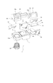
- FIG. 2 is an exploded perspective view
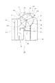
- FIG. 3 is a plane A view of the vehicle air conditioner of FIG. It is sectional drawing at the time of cut
- the vehicle air conditioner 1 is installed so that the front-rear direction in FIG. 1 is the traveling direction of the vehicle, and is roughly divided into a blower mechanism (left side in FIG. 1) that sends an airflow, and an airflow And a temperature conditioning mechanism (right side of FIG. 1) that cools and heats, as shown in FIG. 2, a part of the lower case 10, a part of the first upper case 20, the blower 80, and the inside / outside air switching
- a door 90 or the like constitutes a blowing mechanism, and a part of the lower case 10, a part of the first upper case 20, a second upper case 30, a cooling heat exchanger 40, a heating heat exchanger 50, and an air mix door 60.
- the temperature adjustment mechanism is configured by the mode door 70 (also referred to as a wind door).
- the lower case 10 has a box shape which is disposed below the vehicle in the vertical direction, has a space inside, and is open at the top.
- the plurality of upper cases are stacked one layer above the lower case 10 along the vertical direction of the vehicle, the lower part is opened, and the upper case is combined with the lower case 10 to form an internal space.
- a case 20 and a second upper case 30 are provided.
- the air blow mechanism side has an outside air inlet (not shown) for guiding air outside the vehicle and an inside air inlet 20a for guiding the air inside the first upper case 20.
- the first upper case 20 the defrost opening 21, the second upper case 30, the vent opening 31 for blowing air toward the driver's upper body.
- a foot opening 32 for blowing air to the feet.
- a foot duct 95 may be added to the vehicle air conditioner 1 later as needed.
- the inside / outside air switching door 90 adjusts the ratio of the air taken into the vehicle air conditioner 1 between the outside air introduced from the outside air inlet (not shown) and the inside air introduced from the inside air inlet 20a.
- the cross section is shown as a rotary door having an arc-shaped outer peripheral portion, fan-shaped portions at both ends thereof, and a rotation shaft penetrating through the center portions of the fan-shaped portions on both sides.
- the rotating shaft of the inside / outside air switching door 90 is rotatably held by a bearing portion formed between the end surfaces of the lower case 10 and the first upper case 20, and is illustrated at a portion protruding outward from the case. It is connected with a rotation drive source that does not.
- the inside / outside air switching door 90 can be stopped at an intermediate position.
- the blower 80 guides the air introduced from the outside air inlet (not shown) and / or the inside air inlet 20a to the cooling heat exchanger 40.
- the blower 80 includes an impeller and a motor that rotates the impeller, and is mounted on the blower side of the lower case 10.
- the cooling heat exchanger 40 is disposed in an internal space formed by the lower case 10 and the first upper case 20, and is connected to a known refrigeration cycle. Air that flows through the internal space is circulated. It is possible to cool.
- the heating heat exchanger 50 is an internal space formed by the lower case 10 and the second upper case 30 and is arranged behind the cooling heat exchanger 40 in the front-rear direction of the vehicle. It is connected, and it is possible to heat all or part of the air that has flowed through the cooling heat exchanger 40.
- the second upper case 30 is integrally formed with the second upper case 30 and has a heating heat exchanger holding portion 33 that fixes the heating heat exchanger 50.
- the air mix door 60 uses an airflow (cold air) that bypasses the heating heat exchanger 50 and an airflow that passes through the heating heat exchanger 50 (air) (air) that passes through the cooling heat exchanger 40 and is sent to the mode door 70.
- the ratio with warm air is adjusted.
- it is shown as a cantilever door having a rotating shaft 61 and a closing portion 62 extending from the rotating shaft 61, and between the cooling heat exchanger 40 and the heating heat exchanger 50. Is provided.
- the rotation shaft 61 is rotatably held by a bearing portion 63a formed on the end surface of the lower case 10 and a bearing portion 63b formed on the end surface of the second upper case 30, and the case 20 and 30 are externally extended.
- the protruding portion is connected to a rotation drive source (not shown).
- the mode door 70 distributes the conditioned air to a desired outlet for the air conditioned by the vehicle air conditioner 1.
- the cross section is shown as a rotary door including an outer peripheral portion having an arc shape, fan-shaped portions at both ends thereof, and a rotation shaft penetrating through the central portions of the fan-shaped portions on both sides, and a defrost opening 21
- the vent opening 31 and the foot opening 32 are provided in the vicinity, and an opening for ventilation is appropriately provided on the outer peripheral portion.
- the rotation shaft of the mode door 70 is rotatable by a bearing portion 63c formed on both end surfaces of the second upper case 30 and a bearing portion (not shown) formed on both end surfaces of the first upper case 20.
- the portion that is sandwiched and protrudes from the cases 20 and 30 to the outside is connected to a rotation drive source (not shown).
- FIG. 3 the airflow is indicated by arrows.
- the outside air and / or the inside air introduced into the space formed by the lower case 10, the first upper case 20, and the second upper case 30 from the inside / outside air switching door 90 is directed toward the cooling heat exchanger 40 by the blower 80. And circulated.
- the airflow that has passed through the cooling heat exchanger 40 is guided by the air mix door 60 in the direction of the heating heat exchanger 50 or in the direction not passing through the heating heat exchanger 50 (an alternative route).
- the airflow in both directions can be blown by appropriately changing the mixing ratio.
- the airflow passing through the heating heat exchanger 50 is heated by the heating heat exchanger 50, becomes warm air, and reaches a space (air mix space) where the mode door 70 is disposed.
- the airflow that bypasses the heat exchanger 50 for heating reaches the space (air mix space) in which the mode door 70 is arranged without being heated by the heat exchanger 50 for heating, with the cold air.
- both hot air and cold air are present, they merge in the space (air mix space) in which the mode door 70 is disposed, and the temperatures are harmonized.
- the airflow flows out to a plurality of openings of the defrost opening 21, the vent opening 31, the foot opening 32, or a combination thereof depending on the rotational position of the mode door 70.
- the lower case 10 is placed on a horizontal plane with the opening facing up.
- the cooling heat exchanger 40 is placed on the lower case 10 in an upright position so that the airflow direction is the vehicle front-rear direction. Further, the heat exchanger 50 for heating is similarly placed in a standing position.
- both ends of the rotation shaft 61 of the air mix door 60 are placed on the bearing portion 63 a of the lower case 10. Then, one end of the closing portion 62 of the air mix door 60 is held in a state of being in contact with the contact portion 11 of the lower case 10.
- the second upper case 30 is moved from above, and the heat exchanger 40 for heating is firmly fixed by the heat exchanger holder 33 for heating.
- the rotation shaft 61 of the air mix door 60 is rotatably fixed by the bearing portion 63 b provided in the second upper case 30. Further, conventionally known airtight measures are taken for the fitting portion P2 between the lower case 10 and the second upper case 30.
- the mode door 70 is moved slightly diagonally from above, and both ends of the rotation shaft are placed on the bearing portion 63c of the second upper case 30.
- the first upper case 20 is moved from above and brought into close contact with the lower case 10 to firmly fix the cooling heat exchanger 40.
- the inside / outside air switching door 90 is also rotatably held by the bearing portion 64 a of the lower case 10 and the bearing portion 64 b of the first upper case 20.
- the mode door 70 is also rotatably held by a bearing portion (not shown) of the first upper case 20 and a bearing portion 63c of the second upper case 30.
- conventionally well-known measures against airtightness are also applied to the fitting portion P1 between the lower case 10 and the first upper case 20, and the fitting portion P3 between the first upper case 20 and the second upper case 30.
- suppressing part 33 for a heating when shape
- the heat exchanger holding part 33 for heating is formed separately from the second upper case 30, the degree of freedom in designing the second upper case 30 can be improved.
- cooling heat exchanger 40 and the heating heat exchanger 50 are provided along the vehicle front-rear direction, they may be provided along the vehicle left-right direction. In that case, the air mix door 60 extends in the vehicle front-rear direction. Such an arrangement may be effective depending on the space situation in the vehicle.
- both ends are connected to the lower case 10 and the second case.
- the upper case 20 or one end may be sandwiched between the lower case 10 and the first upper case 20, and the other end may be sandwiched between the lower case 10 and the second upper case 30. It is possible to design appropriately according to the shape of the part and the request from the production process.
- the rotation axis positions of the air mix door 60 and the mode door 70 are different, they may be rotated separately on the same axis as the same position. There is an advantage that only one bearing part is required.
- the door shape is a cantilever type for the air mix door 60 and a rotary type for the mode door 70, but is not limited to this, and any type including a butterfly type having closed portions on both sides of the rotating shaft, etc.
- the door may be used.
- An appropriate mold may be selected based on the request for airflow control and the manufacturing cost.
- the second upper case 30 and the first upper case 20 are assembled in the order of assembling order, but the order may be reversed from the situation such as pre-assembly of other components. In some cases, efficiency can be increased.
- air mix door 60 and the mode door 70 are assembled independently, they may be assembled in advance in the second upper case 30, the first upper case 30, or the lower case 10.
- the advantage that the final assembly is simplified can also be considered.
- the upper case has been described as the first upper case 20 and the second upper case 30, the upper case may be further subdivided to increase the number of upper cases to 3 or more.
- the number of members is increased by changing the air blowing mechanism side of the first upper case to the third upper case.
- the assemblability is improved and the number of assembling steps or time can be reduced, it is effective in reducing the overall cost.
- FIG. 1 is a perspective view of a vehicle air conditioner according to a second embodiment of the present invention, which is common to the first embodiment
- FIG. 4 is an exploded perspective view
- FIG. 5 is a perspective view of FIG. 1 in the second embodiment. It is sectional drawing at the time of cut
- FIG. 1 is a perspective view of a vehicle air conditioner according to a second embodiment of the present invention, which is common to the first embodiment
- FIG. 4 is an exploded perspective view
- FIG. 5 is a perspective view of FIG. 1 in the second embodiment. It is sectional drawing at the time of cut
- the vehicle air conditioner 100 is installed such that the front-rear direction in FIG. 1 is the traveling direction of the vehicle, and is roughly divided into a blower mechanism (left side in FIG. 1) that sends an airflow, and an airflow And a temperature conditioning mechanism (right side of FIG. 1) that cools and heats, as shown in FIG. 4, a part of the lower case 110, a part of the first upper case 120, the blower 180, and the inside / outside air switching
- a door 190 or the like constitutes a blower mechanism, and a part of the lower case 110, a part of the first upper case 120, a second upper case 130, a cooling heat exchanger 140, a heating heat exchanger 150, an air mix door 160.
- the temperature adjustment mechanism is configured by the mode door 170 or the like.
- the lower case 110 has a box shape that is disposed below the vehicle in the vertical direction, has a space inside, and is open at the top.
- the plurality of upper cases are stacked one layer above the lower case 110 along the vertical direction of the vehicle, the lower part is opened, and the lower case 110 is coupled to form an internal space.
- a case 120 and a second upper case 130 are included.
- the first upper case 120 On the air blowing mechanism side, the first upper case 120 has an outside air inlet (not shown) for guiding air outside the vehicle and an inside air inlet 120a for guiding the air inside the vehicle.
- a foot duct 195 may be added to the vehicle air conditioner 100 later as needed.
- the inside / outside air switching door 190 adjusts the ratio of the outside air introduced from the outside air inlet (not shown) and the inside air introduced from the inside air inlet 120a with respect to the air taken into the vehicle air conditioner 100.
- the cross section is shown as a rotary door having an arc-shaped outer peripheral portion, fan-shaped portions at both ends thereof, and rotating shafts penetrating through the central portions of the fan-shaped portions on both sides, and upstream of the blower 180.
- the rotating shaft of the inside / outside air switching door 190 is rotatably held by a bearing portion formed between the end surfaces of the lower case 110 and the first upper case 120, and is illustrated at a portion protruding outward from the case. It is connected with a rotation drive source that does not.
- the inside / outside air switching door 190 can be stopped at an intermediate position.
- the blower 180 guides the air introduced from the outside air inlet (not shown) and / or the inside air inlet 120a to the cooling heat exchanger 140.
- the blower 180 includes an impeller and a motor that rotates the impeller, and is mounted on the blower side of the lower case 110.
- the cooling heat exchanger 140 is disposed in an internal space formed by the lower case 110 and the first upper case 120 and is connected to a well-known refrigeration cycle. Air that flows through the internal space is circulated. It is possible to cool.
- the heating heat exchanger 150 is an internal space formed by the lower case 110 and the second upper case 130, and is disposed behind the cooling heat exchanger 140 in the front-rear direction of the vehicle. It is connected, and it is possible to heat all or part of the air flowing through the cooling heat exchanger 140.
- the second upper case 130 is integrally formed with the second upper case 130 and has a heating heat exchanger holding portion 133 that fixes the heating heat exchanger 150.
- the air mix door 160 has an airflow (cold air) that bypasses the heating heat exchanger 150 and an airflow that passes through the heating heat exchanger 150 (air) that passes through the cooling heat exchanger 140 and is sent to the mode door 170 ( The ratio with warm air is adjusted.
- the cross section is shown as a rotary door comprising an outer peripheral portion having an arc shape, fan-shaped portions at both ends thereof, and a rotating shaft 161 penetrating through the central portions of the fan-shaped portions on both sides.
- the rotation shaft 161 of the air mix door 160 is rotated by a bearing portion 163 a formed on both end surfaces of the second upper case 130 and a bearing portion (not shown) formed on both end surfaces of the first upper case 120. It is clamped so as to be connected to a rotation drive source (not shown) at a portion protruding from the cases 120 and 130 to the outside.
- the mode door 170 distributes conditioned air to a desired outlet for the air conditioned by the vehicle air conditioner 100.
- the cross section is shown as a rotary door including an outer peripheral portion having an arc shape, fan-shaped portions at both ends thereof, and a rotation shaft penetrating through the central portions of the fan-shaped portions on both sides.
- the vent opening 131 and the foot opening 132 are provided in the vicinity, and an opening for ventilation is appropriately provided in the outer peripheral portion.
- the rotation shaft 171 of the mode door 170 is also rotatable by a bearing portion 163a formed on both end surfaces of the second upper case 130 and a bearing portion (not shown) formed on both end surfaces of the first upper case 120. And is connected to a rotation drive source (not shown) at a portion protruding from the cases 120 and 130 to the outside.
- rotation shaft 161 of the air mix door 160 and the rotation shaft 171 of the mode door 170 are arranged on the same axis, they can rotate independently of each other.
- FIG. 5 the airflow is indicated by arrows. Outside air and / or inside air introduced into the space formed by the lower case 110, the first upper case 120, and the second upper case 130 from the inside / outside air switching door 190 is directed toward the cooling heat exchanger 140 by the blower 180. And circulated.
- the airflow that has passed through the cooling heat exchanger 140 is guided by the air mix door 160 in the direction of the heating heat exchanger 150 or in a direction that does not pass through the heating heat exchanger 150 (an alternative route).
- the airflow in both directions can be blown by appropriately changing the mixing ratio.
- the airflow passing through the heating heat exchanger 150 is heated by the heating heat exchanger 150 to become warm air, and reaches a space (air mix space) in which the mode door 170 is disposed.
- the airflow that bypasses the heat exchanger 150 for heating reaches the space (air mix space) in which the mode door 170 is disposed without being heated by the heat exchanger 150 for heating and with the cold air.
- both hot air and cold air are present, they merge in the space (air mix space) in which the mode door 170 is arranged, and the temperatures are harmonized.
- the airflow flows out to a plurality of openings of the defrost opening 121, the vent opening 131, the foot opening 132, or a combination thereof depending on the rotational position of the mode door 170.
- the lower case 110 is placed on a horizontal plane with the opening facing up.
- the cooling heat exchanger 140 is placed on the lower case 110 in an upright position so that the airflow direction is the vehicle front-rear direction. Further, the heat exchanger 150 for heating is similarly placed in a standing position.
- the second upper case 130 is moved from above, and the heating heat exchanger 140 is firmly fixed by the heating heat exchanger pressing portion 133. Further, conventionally known measures for airtightness are applied to the fitting portion P12 of the lower case 110 and the second upper case 130.
- the air mix door 160 and the mode door 170 are temporarily assembled to be rotatable to form a door assembly, and both ends of the rotation shafts 161 and 171 of the door assembly are placed on the bearing portion 163a of the second upper case 130. .
- the first upper case 120 is moved from above and brought into close contact with the lower case 110 to firmly fix the cooling heat exchanger 140.
- the inside / outside air switching door 190 is also rotatably held between the bearing portion 164a of the lower case 110 and the bearing portion 164b of the first upper case 120.
- the mode door 70 is also rotatably held by a bearing portion (not shown) of the first upper case 120 and a bearing portion 163a of the second upper case 130.
- conventionally well-known measures for airtightness are also applied to the fitting portion P11 between the lower case 110 and the first upper case 120 and the fitting portion P13 between the first upper case 120 and the second upper case 130.
- the heat exchanger holding part 133 for heating may be formed integrally with the second upper case 130 or may be formed separately from the second upper case 130.
- the cooling heat exchanger 140 and the heating heat exchanger 150 are provided along the vehicle front-rear direction, but may be provided along the vehicle left-right direction.
- the air mix door 160 extends in the vehicle front-rear direction. Such an arrangement may be effective depending on the space situation in the vehicle.
- the rotation axis positions of the air mix door 160 and the mode door 170 are the same position and coaxial, but may be provided separately at different locations. Advantages such as increased flexibility in layout are also conceivable.
- the door shape is a rotary type for both the air mix door 160 and the mode door 170.
- the present invention is not limited to this, and any type of door including a cantilever type and a butterfly type can be used. It may be used. An appropriate mold may be selected based on the request for airflow control and the manufacturing cost.
- the second upper case 130 and the first upper case 120 are assembled in the order of assembly in the order of assembly, but the order is reversed from the situation such as pre-assembly of other components. Also good. In some cases, efficiency can be increased.
- the air mix door 160 and the mode door 170 are described as being sandwiched between the second upper case 130 and the first upper case 120.
- the air mix door 160 and the mode door 170 may be assembled to the second upper case 130 in advance. May be. The mounting process can be facilitated.
- the heating heat exchanger holding part 133 is in a full hot mode position where the air mix door 160 flows all of the air that has passed through the cooling heat exchanger 140 to the heating heat exchanger 150.
- the air mix door 160 is in the full cool mode position in which all of the air that has passed through the cooling heat exchanger 140 flows to bypass the heating heat exchanger 150, It is preferable to have the sheet part 135 in contact. Air flow can be controlled more reliably.
- the upper case has been described as the first upper case 120 and the second upper case 130.
- the upper case is further subdivided. Good.
- the number of members is increased by changing the air blowing mechanism side of the first upper case to the third upper case.
- the assemblability is improved and the number of assembling steps or time can be reduced, it is effective in reducing the overall cost.
- the lower cases 10 and 110 have been described as being placed on a horizontal plane with the opening side up, but the lower cases 10 and 110 are placed.
- the blowers 80 and 180 may be arranged in front so that the impeller is on the upper side, and the lower cases 10 and 110 may be moved from above and fixed.
- the vehicle air conditioners 1 and 100 including the blowers 80 and 180 can be stacked and assembled from the bottom to the top.
- the vehicle air conditioner according to the present invention is an invention that can be industrially manufactured and can be used as an object of commerce, and thus can be used industrially with economic value.
Landscapes
- Physics & Mathematics (AREA)
- Thermal Sciences (AREA)
- Engineering & Computer Science (AREA)
- Mechanical Engineering (AREA)
- Air-Conditioning For Vehicles (AREA)
Abstract
【課題】 良好な組み付け性を有し、かつ、寸法精度を高くすることのできる車両用空調装置を提供する。 【解決方法】 車両上下方向の下方に配置される下部ケースと、車両上下方向に沿って下部ケースの上方に一層のみ積層されて、下部ケースと内部空間を形成する複数の上部ケースと、内部空間に配置され、該内部空間を通流する空気を冷却可能な冷却用熱交換器と、内部空間のうち冷却用熱交換器よりも車両左右方向のいずれか、又は車両前後方向の後方に配置され、冷却用熱交換器を通流した空気の全部または一部を加熱可能な加熱用熱交換器と、加熱用熱交換器を通流した暖気と加熱用熱交換器を迂回した空気との混合比率を制御するエアミックスドアと、を備える。
Description
本発明は、車両用の空調装置に関し、特に、冷却用熱交換器及び加熱用熱交換器を内蔵し、積層して組み立てることができる車両用の空調装置に関する。
従来から知られた積層型の車両用空調装置としては、例えば、特許文献1に記載されているものがある。これには、ケース内にエバポレータ、ヒータコア等を組み付けてなるエアコンの室内ユニットにおいて、ケースは、エバポレータを上方より装着する下ケースと、下ケースの上に連結する上ケースと、下ケースの下流側に連結する後ケースとに三分割してなる車両用の空調装置の技術思想が開示されている。
これによれば、下ケース、エバポレータ、上ケースの順に上方へと積み重ねて組み付けできる構成としたから、これらの組み付け性がよく、組み付けラインの自動化が可能になるなどの利点がある。
また、特許文献2に記載されているものもある。これには、略平行な分割面にて車両上下方向に少なくとも上・中・下の3つに分割されたケースを有し、これらのケースは車両上下方向に積層されて1つのケースを構成する車両用空調装置の技術思想が開示されている。
更に、3つのケースの内部には、送風空気を冷却する冷却用熱交換器と、複数の吹出開口部を開閉する吹出モード切替ドアが配置されるようになっており、冷却用熱交換器が、中ケース内を貫通して下ケースおよび上ケースの内部に挿入されて固定され、吹出モード切替ドアの回動軸が3つのケースのうち2つのケースの端面間に回動可能に挟み込まれている車両用空調装置の技術思想も開示されている。
これによると、略平行な分割面にて車両上下方向に3つ(上・中・下)に分割されたケースのうち、1つのケース(例えば、下ケース)内に冷却用熱交換器を挿入して、この1つのケースに対して残りの他のケースを積層するとともに、3つのケースのうち2つのケースの端面間に吹出モード切替ドアの回動軸を回動可能に挟み込むことにより、室内空調ユニット部の組み付けを行うことができる。
従って、吹出モード切替ドアの回動軸部の組付のために、事前にサブアッセンブリ単位の組み付け作業を行っておく必要がなく、3つのケース、冷却用熱交換器および吹出モード切替ドアの三者をいずれも下方から上方へと一方向に順次積層していくという、簡潔な作業で室内空調ユニット部の組み付けを行うことができる。これにより、室内空調ユニット部の組み付け工数の低減を実現できる。
しかしながら、上述した特許文献1に開示された車両用空調装置は、ヒータコア及びヒータコアを内蔵する後ケースについては、上方からでなく、気流の下流側から、すなわち、装置の側面からの組み付けになり、組み付けが容易には行えず、自動化の妨げになっているという問題点があった。
更に、特許文献2に開示された車両用空調装置は、ケースが、少なくとも上・中・下の3つに分割されており、上方からの組み付けが可能であるものの、上下方向の結合部がケースの全周にわたって少なくとも2個所あることから、ケース製造時の誤差、あるいは組み付け時の誤差が累積する恐れがあり、装置の寸法精度を悪化させ、気密性や生産性を損なうという問題があった。
そこで、本発明は、良好な組立性を有し、かつ、装置の寸法精度や気密性を高くすることのできる車両用空調装置を提供することを目的としている。
かかる課題を解決するため、本発明の一態様による車両用空調装置は、
車両上下方向の下方に配置される下部ケースと、
車両上下方向に沿って前記下部ケースの上方に一層のみ積層されて、前記下部ケースと内部空間を形成する複数の上部ケースと、
前記内部空間に配置され、該内部空間を通流する空気を冷却可能な冷却用熱交換器(エバポレータともいう)と、
前記内部空間のうち前記冷却用熱交換器よりも車両左右方向のいずれか、又は車両前後方向の後方に配置され、前記冷却用熱交換器を通流した空気の全部または一部を加熱可能な加熱用熱交換器(ヒータともいう)と、
前記加熱用熱交換器を通流した暖気と前記加熱用熱交換器を迂回した空気との混合比率を制御するエアミックスドア(温調ドアともいう)と、
を備えることを特徴とする。
車両上下方向の下方に配置される下部ケースと、
車両上下方向に沿って前記下部ケースの上方に一層のみ積層されて、前記下部ケースと内部空間を形成する複数の上部ケースと、
前記内部空間に配置され、該内部空間を通流する空気を冷却可能な冷却用熱交換器(エバポレータともいう)と、
前記内部空間のうち前記冷却用熱交換器よりも車両左右方向のいずれか、又は車両前後方向の後方に配置され、前記冷却用熱交換器を通流した空気の全部または一部を加熱可能な加熱用熱交換器(ヒータともいう)と、
前記加熱用熱交換器を通流した暖気と前記加熱用熱交換器を迂回した空気との混合比率を制御するエアミックスドア(温調ドアともいう)と、
を備えることを特徴とする。
これによれば、ケースの組み付け方向には、結合部が上部ケースと下部ケースとの積層段数が1階層であるので、積層することによる簡潔な組付け工程を採用できるだけでなく、ケース製造時の誤差、あるいは組付け時の誤差が累積する恐れを減少でき、装置の寸法精度は高く維持され、気密性も確保される。
さらに、下部ケースと複数の上部ケースとで形成される内部空間に、加熱用熱交換器が、冷却用熱交換器よりも車両左右方向のいずれか又は車両前後方向後方に配置されるので、冷却用熱交換器と加熱用熱交換器とが車両上下方向に重ならず、内部空間への2つの熱交換器の組み付け順序を如何様にも選択することができ、生産性を向上できる。
また、本発明の一態様による車両用空調装置は、更に、冷却用熱交換器が、下部ケースと複数の上部ケースのうちの第1上部ケースとにより固定され、加熱用熱交換器が、下部ケースと複数の上部ケースのうちの第2上部ケースとにより固定されることを特徴としてもよい。
これによれば、一般に、冷却用熱交換器と加熱用熱交換器とは車両上下方向の寸法が異なり、冷却用熱交換器の上端部よりも加熱用熱交換器の上端部が低い位置となるところ、それぞれの熱交換機を異なる上部ケースで固定することで、上部ケースと下部ケースとの積層段数が1階層であっても空調装置を構成することができる。
また、本発明の一態様による車両用空調装置は、第2上部ケースは、該第2上部ケースと一体的に成形され、加熱用熱交換器を固定する加熱用熱交換器押さえ部を有することを特徴としてもよい。
これによれば、加熱用熱交換器は、第2上部ケースに一体的に形成された加熱用熱交換器押さえ部により固定されるため、加熱用熱交換器押え部を別部材で構成するのに比べ、構造が簡素化され、部品コスト及び組立工数の削減が可能となる。
また、本発明の一態様による車両用空調装置は、エアミックスドアが、車両左右方向または車両前後方向に沿って、冷却用熱交換器と加熱用熱交換器との間に配置されることを特徴としてもよい。
これによれば、さらにエアミックスドアも、上部ケースと下部ケースとの積層段数が1階層である空調装置の構成部品として、組み付けることができる。
また、本発明の一態様による車両用空調装置は、エアミックスドアが回動軸を有し、該回動軸は、下部ケースと複数の上部ケースのうちいずれかとの端面間に回動可能に挟持されることを特徴としてもよい。
このようにすると、いずれかのケースの端面に軸受部を設ける場合に比べ、部品点数を削減でき、組立工数の削減も期待できる。
また、本発明の別の態様による車両用空調装置は、エアミックスドアが、車両上下方向に沿って、加熱用熱交換器の上方に配置されるロータリドアで、加熱用熱交換器押さえ部は、エアミックスドアが冷却用熱交換器を通流した空気の全部を
(1)加熱用熱交換器へと通流する位置
(2)加熱用熱交換器を迂回するよう通流する位置
のうちいずれか一方、または両方のときに、該エアミックスドアと当接して冷却用熱交換器を通流した空気の流れを制御するシート部を有することを特徴としてもよい。
(1)加熱用熱交換器へと通流する位置
(2)加熱用熱交換器を迂回するよう通流する位置
のうちいずれか一方、または両方のときに、該エアミックスドアと当接して冷却用熱交換器を通流した空気の流れを制御するシート部を有することを特徴としてもよい。
これによれば、ロータリ式のエアミックスドアを有する車両用空調装置でも、上部ケースと下部ケースとの積層段数が1階層である空調装置として構成することができる。
本発明の車両用空調装置によれば、簡潔な組み付け工程で生産できるだけでなく、ケース製造時の誤差、あるいは組み付け時の誤差が累積する恐れを減少した車両用空調装置を提供することができる。
以下、図面を参照し、本発明の第1の実施形態にかかる車両用空調装置について説明する。なお、以下では本発明の目的を達成するための説明に必要な範囲を模式的に示し、本発明の該当部分の説明に必要な範囲を主に説明することとし、説明を省略する箇所については公知技術によるものとする。
図1は、本発明の車両用空調装置の第1及び第2の実施形態の斜視図、図2は分解斜視図、図3は第1の実施形態における図1の車両用空調装置を面Aで切断した場合の断面図である。
第1の実施形態の車両用空調装置1は、図1の前後の方向が、車両の進行方向となるように設置され、大別して、気流を送る送風機構(図1の左方)と、気流を冷却・加熱する温度調和機構(図1の右方)とを有し、図2に示されるように、下部ケース10の一部、第1上部ケース20の一部、送風機80、内外気切替ドア90などで送風機構を構成し、下部ケース10の一部、第1上部ケース20の一部、第2上部ケース30、冷却用熱交換器40、加熱用熱交換器50、エアミックスドア60、モードドア70(配風ドアともいう)などで温度調和機構を構成する。
下部ケース10は、車両の上下方向の下方に配置され、内部に空間を有し、上部が開放されている箱状の形状をしている。
複数の上部ケースは、車両の上下方向に沿って下部ケース10の上方に一層のみ積層されて、下方が開放されており、下部ケース10と結合されて内部空間を形成するもので、第1上部ケース20と第2上部ケース30とを有する。
送風機構側には、第1上部ケース20に、車外の空気を導く外気導入口(図示せず)と車内の空気を導く内気導入口20aとを有する。
また、温度調和機構側には、図3に示されるように、第1上部ケース20に、デフロスト開口部21、第2上部ケース30に、運転者の上半身方向への送風用のベント開口部31と足元への送風用のフット開口部32とを有している。
なお、フット開口部32からの気流を導くため、本車両用空調装置1に後付けで、フットダクト95を必要に応じて付加してもよい。
内外気切替ドア90は、車両用空調装置1に取り込まれる空気について、外気導入口(図示せず)から導入する外気と、内気導入口20aから導入する内気との割合を調整するものである。本実施形態では、断面が円弧状の外周部と、その両端の扇状部分、及び、両側の扇状部分の中心部を貫通する回動軸とを有するロータリドアとして示されており、送風機80の上流側に設けられる。内外気切替ドア90の回動軸は、下部ケース10と第1上部ケース20との端面間に形成された軸受部にて回動可能に挟持され、ケースから外部へ突出した部分にて、図示しない回動駆動源と連結される。内外気切換ドア90は、周知のように、中間の位置で停止することもできる。
送風機80は、外気導入口(図示せず)および/又は内気導入口20aから導入された空気を、冷却用熱交換器40へと導く。送風機80は、インペラと、インペラを回転するモータとを備え、下部ケース10の送風機側に装着される。
冷却用熱交換器40は、下部ケース10と第1上部ケース20とによって形成される内部空間に配置され、また周知の冷凍サイクルと連結されるものであり、その内部空間を通流する空気を冷却することが可能である。
加熱用熱交換器50は、下部ケース10と第2上部ケース30とによって形成される内部空間で、冷却用熱交換器40よりも車両の前後方向の後方に配置され、また周知の温水サイクルと連結されるものであり、冷却用熱交換器40を通流した空気の全部または一部を加熱することが可能である。
なお、第2上部ケース30は、第2上部ケース30と一体的に成形され、加熱用熱交換器50を固定する加熱用熱交換器押さえ部33を有する。
エアミックスドア60は、冷却用熱交換器40を通過してモードドア70に送られる空気について、加熱用熱交換器50を迂回する気流(冷風)と加熱用熱交換器50を経由する気流(温風)との割合を調整するものである。本実施形態では、回動軸61と回動軸61から延出する閉塞部62とを有する片持ち式ドアとして示されており、冷却用熱交換器40と加熱用熱交換器50との間に設けられる。回動軸61は、下部ケース10の端面に形成された軸受部63aと第2上部ケース30との端面に形成された軸受部63bとにより回動可能に挟持され、ケース20、30から外部へ突出した部分にて、図示しない回動駆動源と連結される。
モードドア70は、車両用空調装置1により温度調和された空気について、所望する吹出口に調和空気を配風するものである。本実施形態では、断面が円弧状の外周部と、その両端の扇状部分、及び、両側の扇状部分の中心部を貫通する回動軸とからなるロータリドアとして示されており、デフロスト開口部21、ベント開口部31、フット開口部32の近傍に設けられるとともに、外周部には通気のための開口部が適宜設けられている。モードドア70の回動軸は、第2上部ケース30の両端面に形成された軸受部63cと第1上部ケース20の両端面に形成された軸受部(図示せず)とにより回動可能に挟持され、ケース20、30から外部へ突出した部分にて、図示しない回動駆動源と連結される。
次に、このような構成の車両用空調装置1の動作を説明する。図3において、気流は矢印で示される。内外気切替ドア90より、下部ケース10、第1上部ケース20、第2上部ケース30で形成される空間に導入される外気および/または内気は、送風機80により、冷却用熱交換器40方向へと通流される。
冷却用熱交換器40を通過した気流は、エアミックスドア60によって、加熱用熱交換器50の方向へ、あるいは加熱用熱交換器50を通らない方向(迂回経路)へと導かれる。エアミックスドア60の回動位置によっては、両方向に向かう気流を、適宜、混合比率を変えて送風することができる。
加熱用熱交換器50を経由する気流は、加熱用熱交換器50により加熱され、温風となり、モードドア70が配置される空間(エアミックス空間)へ到達する。加熱用熱交換器50を迂回する気流は、加熱用熱交換器50で加熱されることなく、冷風のまま、モードドア70が配置される空間(エアミックス空間)へ到達する。温風と冷風との両方が存在する場合、モードドア70が配置される空間(エアミックス空間)にて合流し、温度が調和される。
その後、気流は、モードドア70の回動位置に応じて、デフロスト開口部21、ベント開口部31、フット開口部32のいずれか、あるいは、それらの組合せの複数の開口部へと流出される。
ここで、本発明の第1の実施形態の車両用空調装置1の組立方法について図2及び図3に基づいて説明する。まず、下部ケース10を、開口部を上にして、水平面に載置する。
次いで、下部ケース10に、冷却用熱交換器40を、気流の通過方向が車両前後方向になるように、立位で載置する。更に加熱用熱交換器50も、同様に、立位で載置する。
引き続き、エアミックスドア60の回動軸61の両端を、下部ケース10の軸受部63aに載置する。すると、エアミックスドア60の閉塞部62の一端は、下部ケース10の当接部11に当接した状態で保持されることになる。
次に、第2上部ケース30を上方より移動させ、加熱用熱交換器40については、加熱用熱交換器押さえ部33によってしっかりと固定する。この際に、第2上部ケース30に設けられた軸受部63bによってエアミックスドア60の回動軸61が回動自由に固定される。更に、下部ケース10と第2上部ケース30の嵌合部P2については、従来周知の気密対策を施される。
次に、モードドア70をやや斜め上方より移動させ、その回動軸の両端を、第2上部ケース30の軸受部63cに載置する。
次に、内外気切替ドア90の回動軸を、下部ケース10の軸受部64aに載置する。
次に、第1上部ケース20を上方より移動させ、下部ケース10と密着させて、冷却用熱交換器40をしっかりと固定する。内外気切替ドア90についても、下部ケース10の軸受部64aと第1上部ケース20の軸受部64bにて回動可能に挟持する。モードドアドア70についても、第1上部ケース20の軸受部(図示せず)と第2上部ケース30の軸受部63cにて回動可能に挟持する。更に、下部ケース10と第1上部ケース20の嵌合部P1や、第1上部ケース20と第2上部ケース30との嵌合部P3についても、従来周知の気密対策を施される。
このようにすると、車両用空調装置の全ての要素(一部の事前組み付け要素を除く)が、上方から順次組み付けることが可能であり、作業の効率化、自動化(ロボット化)に極めて有効である。
なお、加熱用熱交換器押さえ部33について、第2上部ケース30と一体的に成形される場合は、ケースの部品数を減少できる。加熱用熱交換器押さえ部33が、第2上部ケース30と別体で成形される場合は、第2上部ケース30の設計自由度を向上できる。
また、冷却用熱交換器40と加熱用熱交換器50とは、車両前後方向に沿って設けられるとしたが、車両左右方向に沿って設けてもよい。その場合、エアミックスドア60は、車両前後方向に延伸することとする。このような配置は、車両内のスペースの状況によっては有効な場合もある。
また、エアミックスドア60の回動軸61は、下部ケース10と第2上部ケース30との端面の軸受部63a、bに回動可能に挟持されるとしたが、両端を下部ケース10と第1上部ケース20、または一方の端を下部ケース10と第1上部ケース20、他方の端を下部ケース10と第2上部ケース30により挟持されるよう構成しても良い。部品の形状や生産工程からの要請に応じて、適宜設計することができる。
また、エアミックスドア60とモードドア70の回動軸位置は、別々であるが、同一位置として、同軸上で、別個に回動できるようにしてもよい。軸受部分が一個所で済む利点がある。
また、ドア形状も、エアミックスドア60を片持ち型、モードドア70をロータリ型としたが、それに限定されず、回動軸の両側に閉塞部を設けたバタフライ型なども含めて、どの型のドアを用いてもよい。気流の制御の要請及び製造コストなどから、適切な型を選択すればよい。
また、組立順序につき、第2上部ケース30、第1上部ケース20の順に組み付けるとしたが、他の構成部品の事前組み付けなどの状況から、その順序を逆にしてもよい。効率が上昇できる場合もある。
また、エアミックスドア60やモードドア70は、単独で組み付けるようにしたが、予め、第2上部ケース30、第1上部ケース30、または下部ケース10に事前組み付けされていてもよい。その方が、最終組立が簡素化される利点も考えられる。
また、上部ケースは、第1上部ケース20と第2上部ケース30との2つとして説明したが、更に細分して、上部ケースの数を3以上に増してもよい。例えば、第1上部ケースの送風機構側を第3上部ケースとするなどで、部材の数は増すが、組立性が改善され、組立工数あるいは時間が短縮できれば、全体のコスト削減に有効である。
次に、本発明の第2の実施形態による車両用空調装置について説明する。図1は第1の実施形態と共通で、本発明の第2の実施形態の車両用空調装置の斜視図であり、図4は分解斜視図、図5は第2の実施形態における図1の車両用空調装置100を面Aで切断した場合の断面図である。
第2の実施形態の車両用空調装置100は、図1の前後の方向が、車両の進行方向となるように設置され、大別して、気流を送る送風機構(図1の左方)と、気流を冷却・加熱する温度調和機構(図1の右方)とを有し、図4に示されるように、下部ケース110の一部、第1上部ケース120の一部、送風機180、内外気切替ドア190などで送風機構を構成し、下部ケース110の一部、第1上部ケース120の一部、第2上部ケース130、冷却用熱交換器140、加熱用熱交換器150、エアミックスドア160、モードドア170などで温度調和機構を構成する。
下部ケース110は、車両の上下方向の下方に配置され、内部に空間を有し、上部が開放されている箱状の形状をしている。
複数の上部ケースは、車両の上下方向に沿って下部ケース110の上方に一層のみ積層されて、下方が開放されており、下部ケース110と結合されて内部空間を形成するもので、第1上部ケース120と第2上部ケース130とを有する。
送風機構側には、第1上部ケース120に、車外の空気を導く外気導入口(図示せず)と車内の空気を導く内気導入口120aとを有する。
また、温度調和機構側には、図5に示されるように、第1上部ケース120に、デフロスト開口部121、第2上部ケース130に、運転者の上半身方向への送風用のベント開口部131と足元への送風用のフット開口部132とを有している。
なお、フット開口部121からの気流を導くため、本車両用空調装置100に後付けで、フットダクト195を必要に応じて付加してもよい。
内外気切替ドア190は、車両用空調装置100に取り込まれる空気について、外気導入口(図示せず)から導入する外気と、内気導入口120aから導入する内気との割合を調整するものである。本実施形態では、断面が円弧状の外周部と、その両端の扇状部分、及び、両側の扇状部分の中心部を貫通する回動軸とを有するロータリドアとして示されており、送風機180の上流側に設けられる。内外気切替ドア190の回動軸は、下部ケース110と第1上部ケース120との端面間に形成された軸受部にて回動可能に挟持され、ケースから外部へ突出した部分にて、図示しない回動駆動源と連結される。内外気切換ドア190は、周知のように、中間の位置で停止することもできる。
送風機180は、外気導入口(図示せず)および/又は内気導入口120aから導入された空気を、冷却用熱交換器140へと導く。送風機180は、インペラと、インペラを回転するモータとを備え、下部ケース110の送風機側に装着される。
冷却用熱交換器140は、下部ケース110と第1上部ケース120とによって形成される内部空間に配置され、また周知の冷凍サイクルと連結されるものであり、その内部空間を通流する空気を冷却することが可能である。
加熱用熱交換器150は、下部ケース110と第2上部ケース130とによって形成される内部空間で、冷却用熱交換器140よりも車両の前後方向の後方に配置され、また周知の温水サイクルと連結されるものであり、冷却用熱交換器140を通流した空気の全部または一部を加熱することが可能である。
なお、第2上部ケース130は、第2上部ケース130と一体的に成形され、加熱用熱交換器150を固定する加熱用熱交換器押さえ部133を有する。
エアミックスドア160は、冷却用熱交換器140を通過してモードドア170に送られる空気について、加熱用熱交換器150を迂回する気流(冷風)と加熱用熱交換器150を経由する気流(温風)との割合を調整するものである。本実施形態では、断面が円弧状の外周部と、その両端の扇状部分、及び、両側の扇状部分の中心部を貫通する回動軸161とからなるロータリドアとして示されており、加熱用熱交換器150の上方に設けられる。エアミックスドア160の回動軸161は、第2上部ケース130の両端面に形成された軸受部163aと第1上部ケース120の両端面に形成された軸受部(図示せず)とにより回動可能に挟持され、ケース120、130から外部へ突出した部分にて、図示しない回動駆動源と連結される。
モードドア170は、車両用空調装置100により温度調和された空気について、所望する吹出口に調和空気を配風するものである。本実施形態では、断面が円弧状の外周部と、その両端の扇状部分、及び、両側の扇状部分の中心部を貫通する回動軸とからなるロータリドアとして示されており、デフロスト開口部121、ベント開口部131、フット開口部132の近傍に設けられるとともに、外周部には通気のための開口部が適宜設けられている。モードドア170の回動軸171も、第2上部ケース130の両端面に形成された軸受部163aと第1上部ケース120の両端面に形成された軸受部(図示せず)とにより回動可能に挟持され、ケース120、130から外部へ突出した部分にて、図示しない回動駆動源と連結される。
エアミックスドア160の回動軸161と、モードドア170の回動軸171とは同じ軸線上に配置されているが、それぞれ独立して回動することが可能である。
次に、このような構成の車両用空調装置100の動作を説明する。図5において、気流は矢印で示される。内外気切替ドア190より、下部ケース110、第1上部ケース120、第2上部ケース130で形成される空間に導入される外気および/または内気は、送風機180により、冷却用熱交換器140方向へと通流される。
冷却用熱交換器140を通過した気流は、エアミックスドア160によって加熱用熱交換器150の方向へ、あるいは加熱用熱交換器150を通らない方向(迂回経路)へと導かれる。エアミックスドア160の回動位置によっては、両方向に向かう気流を、適宜、混合比率を変えて送風することができる。
加熱用熱交換器150を経由する気流は、加熱用熱交換器150により加熱され、温風となり、モードドア170が配置される空間(エアミックス空間)へ到達する。加熱用熱交換器150を迂回する気流は、加熱用熱交換器150で加熱されることなく、冷風のまま、モードドア170が配置される空間(エアミックス空間)へ到達する。温風と冷風との両方が存在する場合、モードドア170が配置される空間(エアミックス空間)にて合流し、温度が調和される。
その後、気流は、モードドア170の回動位置に応じて、デフロスト開口部121、ベント開口部131、フット開口部132のいずれか、あるいは、それらの組合せの複数の開口部へと流出される。
ここで、本発明の第2の実施形態の車両用空調装置100の組立方法について図4及び図5に基づいて説明する。まず、下部ケース110を、開口部を上にして、水平面に載置する。
次いで、下部ケース110に、冷却用熱交換器140を、気流の通過方向が車両前後方向になるように、立位で載置する。更に加熱用熱交換器150も、同様に、立位で載置する。
次に、第2上部ケース130を上方より移動させ、加熱用熱交換器140については、加熱用熱交換器押さえ部133によってしっかりと固定する。更に、下部ケース110と第2上部ケース130の嵌合部P12については、従来周知の気密対策が施される。
次いで、エアミックスドア160とモードドア170とを回動可能に仮組みし、ドアアセンブリとし、ドアアセンブリの回動軸161、171の両端を、第2上部ケース130の軸受部163aに載置する。
次に、内外気切替ドア190の回動軸を、下部ケース110の軸受部164aに載置する。
次に、第1上部ケース120を上方より移動させ、下部ケース110と密着させて、冷却用熱交換器140をしっかりと固定する。内外気切替ドア190についても、下部ケース110の軸受部164aと第1上部ケース120の軸受部164bにて回動可能に挟持する。モードドアドア70についても、第1上部ケース120の軸受部(図示せず)と第2上部ケース130の軸受部163aにて回動可能に挟持する。更に、下部ケース110と第1上部ケース120の嵌合部P11や、第1上部ケース120と第2上部ケース130との嵌合部P13についても、従来周知の気密対策を施される。
このようにすると、車両用空調装置の全ての要素(一部の事前組み付け要素を除く)が、上方から順次組み付けることが可能であり、作業の効率化、自動化(ロボット化)に極めて有効である。
なお、加熱用熱交換器押さえ部133についても、第2上部ケース130と一体的に成形されるものであっても、第2上部ケース130と別体で成形されるものであってもよい。
また、第2の実施形態においても、冷却用熱交換器140と加熱用熱交換器150とは、車両前後方向に沿って設けられるとしたが、車両左右方向に沿って設けてもよい。その場合、エアミックスドア160は、車両前後方向に延伸することとする。このような配置は、車両内のスペースの状況によっては有効な場合もある。
また、第2の実施形態においては、エアミックスドア160とモードドア170の回動軸位置は、同一位置で、同軸上としたが、異なる場所に別々に設けてもよい。レイアウトに自由度が増すなどの利点も考えられる。
また、第2の実施形態においては、ドア形状を、エアミックスドア160、モードドア170ともにロータリ型としたが、それに限定されず、片持ち型、バタフライ型なども含めて、どの型のドアを用いてもよい。気流の制御の要請及び製造コストなどから、適切な型を選択すればよい。
また、第2の実施形態においては、組立順序につき、第2上部ケース130、第1上部ケース120の順に組み付けるとしたが、他の構成部品の事前組み付けなどの状況から、その順序を逆にしてもよい。効率が上昇できる場合もある。
また、第2の実施形態においては、エアミックスドア160やモードドア170は、第2上部ケース130と第1上部ケース120とで挟持するとして説明したが、予め第2上部ケース130に組み付けるようにしてもよい。載置工程を容易化することができる。
また、加熱用熱交換器押さえ部133は、エアミックスドア160が、冷却用熱交換器140を通流した空気の全部を加熱用熱交換器150へと通流するフルホットモードの位置のときに、エアミックスドア160と当接するシート部134を有していることが望ましい。あるいは、エアミックスドア160が、冷却用熱交換器140を通流した空気の全部を加熱用熱交換器150を迂回するよう通流するフルクールモードの位置のときに、エアミックスドア160と当接するシート部135を有していることが好ましい。より確実に空気の通流を制御できる。
また、第2の実施形態においても、上部ケースは、第1上部ケース120と第2上部ケース130との2つとして説明したが、更に細分して、上部ケースの数を3以上に増してもよい。例えば、第1上部ケースの送風機構側を第3上部ケースとするなどで、部材の数は増すが、組立性が改善され、組立工数あるいは時間が短縮できれば、全体のコスト削減に有効である。
また、第1の実施形態および第2の実施形態の組み立て方法において、下部ケース10、110を、開口側を上にして水平面に載置するとして説明したが、下部ケース10、110を載置する前に送風機80、180をインペラが上方となるように配置し、下部ケース10、110を上方より移動させ、固定してもよい。送風機80、180も含めて、車両用空調装置1、100を下方から上方へと積み重ねて組み付けることができる。
本発明に係る車両用空調装置は、工業的に製造することができ、また商取引の対象とすることができるから、経済的価値を有して産業上利用することができる発明である。
1、100 車両用空調装置
10、110 下部ケース
20、120 第1上部ケース
30、130 第2上部ケース
40、140 冷却用熱交換器
50、150 加熱用熱交換器
60、160 エアミックスドア
70、170 モードドア
P1、P2、P3 嵌合部
P11、P12、P13 嵌合部
10、110 下部ケース
20、120 第1上部ケース
30、130 第2上部ケース
40、140 冷却用熱交換器
50、150 加熱用熱交換器
60、160 エアミックスドア
70、170 モードドア
P1、P2、P3 嵌合部
P11、P12、P13 嵌合部
Claims (6)
- 車両上下方向の下方に配置される下部ケースと、
車両上下方向に沿って前記下部ケースの上方に一層のみ積層されて、前記下部ケースと内部空間を形成する複数の上部ケースと、
前記内部空間に配置され、該内部空間を通流する空気を冷却可能な冷却用熱交換器と、
前記内部空間のうち前記冷却用熱交換器よりも車両左右方向のいずれか、又は車両前後方向の後方に配置され、前記冷却用熱交換器を通流した空気の全部または一部を加熱可能な加熱用熱交換器と、
前記加熱用熱交換器を通流した暖気と前記加熱用熱交換器を迂回した空気との混合比率を制御するエアミックスドアと、
を備えることを特徴とする車両用空調装置。 - 前記冷却用熱交換器は、前記下部ケースと前記複数の上部ケースのうちの第1上部ケースとにより固定され、
前記加熱用熱交換器は、前記下部ケースと前記複数の上部ケースのうちの第2上部ケースとにより固定される
ことを特徴とする請求項1に記載の車両用空調装置。 - 前記第2上部ケースは、該第2上部ケースと一体的に成形され、前記加熱用熱交換器を固定する加熱用熱交換器押さえ部を有する
ことを特徴とする請求項2に記載の車両用空調装置。 - 前記エアミックスドアは、車両左右方向または車両前後方向に沿って、前記冷却用熱交換器と前記加熱用熱交換器との間に配置される
ことを特徴とする請求項1乃至請求項3のいずれかに記載の車両用空調装置。 - 前記エアミックスドアは回動軸を有し、該回動軸は、前記下部ケースと前記複数の上部ケースのうちいずれかの端面間に回動可能に挟持される
ことを特徴とする請求項1乃至請求項4のいずれかに記載の車両用空調装置。 - 前記エアミックスドアは、車両上下方向に沿って、前記加熱用熱交換器の上方に配置されるロータリドアで、
前記加熱用熱交換器押さえ部は、前記エアミックスドアが前記冷却用熱交換器を通流した空気の全部を
(1)前記加熱用熱交換器へと通流する位置
(2)前記加熱用熱交換器を迂回するよう通流する位置
のうちいずれか一方、または両方のときに、該エアミックスドアと当接して前記冷却用熱交換器を通流した空気の流れを制御するシート部を有する
ことを特徴とする請求項3に記載の車両用空調装置。
Priority Applications (2)
| Application Number | Priority Date | Filing Date | Title |
|---|---|---|---|
| CN201680042521.0A CN107848366B (zh) | 2015-08-03 | 2016-07-29 | 车辆用空调装置 |
| JP2017532565A JP6743017B2 (ja) | 2015-08-03 | 2016-07-29 | 車両用空調装置 |
Applications Claiming Priority (2)
| Application Number | Priority Date | Filing Date | Title |
|---|---|---|---|
| JP2015-153305 | 2015-08-03 | ||
| JP2015153305 | 2015-08-03 |
Publications (1)
| Publication Number | Publication Date |
|---|---|
| WO2017022652A1 true WO2017022652A1 (ja) | 2017-02-09 |
Family
ID=57943177
Family Applications (1)
| Application Number | Title | Priority Date | Filing Date |
|---|---|---|---|
| PCT/JP2016/072271 Ceased WO2017022652A1 (ja) | 2015-08-03 | 2016-07-29 | 車両用空調装置 |
Country Status (3)
| Country | Link |
|---|---|
| JP (1) | JP6743017B2 (ja) |
| CN (1) | CN107848366B (ja) |
| WO (1) | WO2017022652A1 (ja) |
Cited By (4)
| Publication number | Priority date | Publication date | Assignee | Title |
|---|---|---|---|---|
| WO2019021707A1 (ja) * | 2017-07-25 | 2019-01-31 | 株式会社デンソー | 車両用空調ユニット |
| JP2019135137A (ja) * | 2017-07-25 | 2019-08-15 | 株式会社デンソー | 車両用空調ユニット |
| CN111372799A (zh) * | 2017-11-24 | 2020-07-03 | 法雷奥日本株式会社 | 车辆用空调装置 |
| KR20240177755A (ko) * | 2023-06-19 | 2024-12-30 | 에이에스텍 주식회사 | 영역별 제어기능을 갖는 전기자동차용 냉난방 송풍 장치 |
Families Citing this family (1)
| Publication number | Priority date | Publication date | Assignee | Title |
|---|---|---|---|---|
| CN109059131A (zh) * | 2018-06-25 | 2018-12-21 | 李佳雯 | 基于神经网络预测的中央空调调节装置 |
Citations (2)
| Publication number | Priority date | Publication date | Assignee | Title |
|---|---|---|---|---|
| JP2005349942A (ja) * | 2004-06-10 | 2005-12-22 | Denso Corp | 車両用空調装置 |
| JP2007083956A (ja) * | 2005-09-26 | 2007-04-05 | Denso Corp | 車両用空調装置 |
Family Cites Families (3)
| Publication number | Priority date | Publication date | Assignee | Title |
|---|---|---|---|---|
| CN100480081C (zh) * | 2004-07-30 | 2009-04-22 | 株式会社杰克赛尔法雷奥空调 | 车辆用空调装置 |
| KR20100010380A (ko) * | 2008-07-22 | 2010-02-01 | 주식회사 두원공조 | 차량 공조장치의 믹스도어 |
| JP5617779B2 (ja) * | 2011-07-06 | 2014-11-05 | 株式会社デンソー | 車両用空調装置 |
-
2016
- 2016-07-29 WO PCT/JP2016/072271 patent/WO2017022652A1/ja not_active Ceased
- 2016-07-29 JP JP2017532565A patent/JP6743017B2/ja active Active
- 2016-07-29 CN CN201680042521.0A patent/CN107848366B/zh active Active
Patent Citations (2)
| Publication number | Priority date | Publication date | Assignee | Title |
|---|---|---|---|---|
| JP2005349942A (ja) * | 2004-06-10 | 2005-12-22 | Denso Corp | 車両用空調装置 |
| JP2007083956A (ja) * | 2005-09-26 | 2007-04-05 | Denso Corp | 車両用空調装置 |
Cited By (7)
| Publication number | Priority date | Publication date | Assignee | Title |
|---|---|---|---|---|
| WO2019021707A1 (ja) * | 2017-07-25 | 2019-01-31 | 株式会社デンソー | 車両用空調ユニット |
| JP2019135137A (ja) * | 2017-07-25 | 2019-08-15 | 株式会社デンソー | 車両用空調ユニット |
| US11407271B2 (en) | 2017-07-25 | 2022-08-09 | Denso Corporation | Air-conditioning unit for vehicle |
| CN111372799A (zh) * | 2017-11-24 | 2020-07-03 | 法雷奥日本株式会社 | 车辆用空调装置 |
| CN111372799B (zh) * | 2017-11-24 | 2022-11-22 | 法雷奥日本株式会社 | 车辆用空调装置 |
| KR20240177755A (ko) * | 2023-06-19 | 2024-12-30 | 에이에스텍 주식회사 | 영역별 제어기능을 갖는 전기자동차용 냉난방 송풍 장치 |
| KR102820324B1 (ko) | 2023-06-19 | 2025-06-16 | 에이에스텍 주식회사 | 영역별 제어기능을 갖는 전기자동차용 냉난방 송풍 장치 |
Also Published As
| Publication number | Publication date |
|---|---|
| CN107848366B (zh) | 2020-04-14 |
| CN107848366A (zh) | 2018-03-27 |
| JP6743017B2 (ja) | 2020-08-19 |
| JPWO2017022652A1 (ja) | 2018-05-24 |
Similar Documents
| Publication | Publication Date | Title |
|---|---|---|
| JP4253960B2 (ja) | 車両用空調装置 | |
| JP6341114B2 (ja) | 車両用空調装置 | |
| JP6743017B2 (ja) | 車両用空調装置 | |
| US20140335774A1 (en) | Convex grid shape to reduce turbulence under rotary door | |
| US6749008B2 (en) | Vehicle air-conditioning system | |
| WO2014058009A1 (ja) | 車両用空調装置 | |
| JP4894447B2 (ja) | 車両用空調装置 | |
| JP2009143338A (ja) | 車両用空調装置 | |
| KR20180033915A (ko) | 차량용 공조장치 | |
| JP3760582B2 (ja) | 車両用空調装置用ドア手段の駆動回転軸組付機構 | |
| JP2006001378A (ja) | 車両用空調装置 | |
| JP4985604B2 (ja) | 車両用空調装置 | |
| JP2015128938A (ja) | 車両用送風機および車両用空調装置 | |
| JP2009018644A (ja) | 車両用空調装置 | |
| JP4285348B2 (ja) | 車両用空調装置 | |
| JP2009006896A (ja) | 車両用空調装置 | |
| JP2018188070A (ja) | 車両用空調装置 | |
| JP3873433B2 (ja) | 車両用空調装置 | |
| JP4487436B2 (ja) | 空調装置のリンクプレート構造 | |
| JP2010260435A (ja) | 車両用空調装置のダンパ駆動構造 | |
| JP2003220820A (ja) | 車両用空調装置 | |
| JP4397614B2 (ja) | 車両用空調装置 | |
| JP4362816B2 (ja) | 空調ユニット | |
| JP4123901B2 (ja) | 車両用空調装置 | |
| KR102238277B1 (ko) | 차량용 공조장치 |
Legal Events
| Date | Code | Title | Description |
|---|---|---|---|
| 121 | Ep: the epo has been informed by wipo that ep was designated in this application |
Ref document number: 16832931 Country of ref document: EP Kind code of ref document: A1 |
|
| ENP | Entry into the national phase |
Ref document number: 2017532565 Country of ref document: JP Kind code of ref document: A |
|
| NENP | Non-entry into the national phase |
Ref country code: DE |
|
| 122 | Ep: pct application non-entry in european phase |
Ref document number: 16832931 Country of ref document: EP Kind code of ref document: A1 |