WO2017018252A1 - 希土類系焼結磁石の製造方法 - Google Patents
希土類系焼結磁石の製造方法 Download PDFInfo
- Publication number
- WO2017018252A1 WO2017018252A1 PCT/JP2016/071015 JP2016071015W WO2017018252A1 WO 2017018252 A1 WO2017018252 A1 WO 2017018252A1 JP 2016071015 W JP2016071015 W JP 2016071015W WO 2017018252 A1 WO2017018252 A1 WO 2017018252A1
- Authority
- WO
- WIPO (PCT)
- Prior art keywords
- coating film
- sintered magnet
- heat treatment
- rtb
- powder
- Prior art date
- Legal status (The legal status is an assumption and is not a legal conclusion. Google has not performed a legal analysis and makes no representation as to the accuracy of the status listed.)
- Ceased
Links
Images
Classifications
-
- B—PERFORMING OPERATIONS; TRANSPORTING
- B22—CASTING; POWDER METALLURGY
- B22F—WORKING METALLIC POWDER; MANUFACTURE OF ARTICLES FROM METALLIC POWDER; MAKING METALLIC POWDER; APPARATUS OR DEVICES SPECIALLY ADAPTED FOR METALLIC POWDER
- B22F3/00—Manufacture of workpieces or articles from metallic powder characterised by the manner of compacting or sintering; Apparatus specially adapted therefor ; Presses and furnaces
- B22F3/24—After-treatment of workpieces or articles
-
- C—CHEMISTRY; METALLURGY
- C22—METALLURGY; FERROUS OR NON-FERROUS ALLOYS; TREATMENT OF ALLOYS OR NON-FERROUS METALS
- C22C—ALLOYS
- C22C28/00—Alloys based on a metal not provided for in groups C22C5/00 - C22C27/00
-
- C—CHEMISTRY; METALLURGY
- C23—COATING METALLIC MATERIAL; COATING MATERIAL WITH METALLIC MATERIAL; CHEMICAL SURFACE TREATMENT; DIFFUSION TREATMENT OF METALLIC MATERIAL; COATING BY VACUUM EVAPORATION, BY SPUTTERING, BY ION IMPLANTATION OR BY CHEMICAL VAPOUR DEPOSITION, IN GENERAL; INHIBITING CORROSION OF METALLIC MATERIAL OR INCRUSTATION IN GENERAL
- C23C—COATING METALLIC MATERIAL; COATING MATERIAL WITH METALLIC MATERIAL; SURFACE TREATMENT OF METALLIC MATERIAL BY DIFFUSION INTO THE SURFACE, BY CHEMICAL CONVERSION OR SUBSTITUTION; COATING BY VACUUM EVAPORATION, BY SPUTTERING, BY ION IMPLANTATION OR BY CHEMICAL VAPOUR DEPOSITION, IN GENERAL
- C23C10/00—Solid state diffusion of only metal elements or silicon into metallic material surfaces
- C23C10/28—Solid state diffusion of only metal elements or silicon into metallic material surfaces using solids, e.g. powders, pastes
- C23C10/34—Embedding in a powder mixture, i.e. pack cementation
- C23C10/52—Embedding in a powder mixture, i.e. pack cementation more than one element being diffused in one step
-
- H—ELECTRICITY
- H01—ELECTRIC ELEMENTS
- H01F—MAGNETS; INDUCTANCES; TRANSFORMERS; SELECTION OF MATERIALS FOR THEIR MAGNETIC PROPERTIES
- H01F1/00—Magnets or magnetic bodies characterised by the magnetic materials therefor; Selection of materials for their magnetic properties
- H01F1/01—Magnets or magnetic bodies characterised by the magnetic materials therefor; Selection of materials for their magnetic properties of inorganic materials
- H01F1/03—Magnets or magnetic bodies characterised by the magnetic materials therefor; Selection of materials for their magnetic properties of inorganic materials characterised by their coercivity
- H01F1/032—Magnets or magnetic bodies characterised by the magnetic materials therefor; Selection of materials for their magnetic properties of inorganic materials characterised by their coercivity of hard-magnetic materials
- H01F1/04—Magnets or magnetic bodies characterised by the magnetic materials therefor; Selection of materials for their magnetic properties of inorganic materials characterised by their coercivity of hard-magnetic materials metals or alloys
- H01F1/047—Alloys characterised by their composition
- H01F1/053—Alloys characterised by their composition containing rare earth metals
- H01F1/055—Alloys characterised by their composition containing rare earth metals and magnetic transition metals, e.g. SmCo5
- H01F1/057—Alloys characterised by their composition containing rare earth metals and magnetic transition metals, e.g. SmCo5 and IIIa elements, e.g. Nd2Fe14B
-
- H—ELECTRICITY
- H01—ELECTRIC ELEMENTS
- H01F—MAGNETS; INDUCTANCES; TRANSFORMERS; SELECTION OF MATERIALS FOR THEIR MAGNETIC PROPERTIES
- H01F1/00—Magnets or magnetic bodies characterised by the magnetic materials therefor; Selection of materials for their magnetic properties
- H01F1/01—Magnets or magnetic bodies characterised by the magnetic materials therefor; Selection of materials for their magnetic properties of inorganic materials
- H01F1/03—Magnets or magnetic bodies characterised by the magnetic materials therefor; Selection of materials for their magnetic properties of inorganic materials characterised by their coercivity
- H01F1/032—Magnets or magnetic bodies characterised by the magnetic materials therefor; Selection of materials for their magnetic properties of inorganic materials characterised by their coercivity of hard-magnetic materials
- H01F1/04—Magnets or magnetic bodies characterised by the magnetic materials therefor; Selection of materials for their magnetic properties of inorganic materials characterised by their coercivity of hard-magnetic materials metals or alloys
- H01F1/06—Magnets or magnetic bodies characterised by the magnetic materials therefor; Selection of materials for their magnetic properties of inorganic materials characterised by their coercivity of hard-magnetic materials metals or alloys in the form of particles, e.g. powder
- H01F1/08—Magnets or magnetic bodies characterised by the magnetic materials therefor; Selection of materials for their magnetic properties of inorganic materials characterised by their coercivity of hard-magnetic materials metals or alloys in the form of particles, e.g. powder pressed, sintered, or bound together
-
- H—ELECTRICITY
- H01—ELECTRIC ELEMENTS
- H01F—MAGNETS; INDUCTANCES; TRANSFORMERS; SELECTION OF MATERIALS FOR THEIR MAGNETIC PROPERTIES
- H01F41/00—Apparatus or processes specially adapted for manufacturing or assembling magnets, inductances or transformers; Apparatus or processes specially adapted for manufacturing materials characterised by their magnetic properties
- H01F41/02—Apparatus or processes specially adapted for manufacturing or assembling magnets, inductances or transformers; Apparatus or processes specially adapted for manufacturing materials characterised by their magnetic properties for manufacturing cores, coils, or magnets
-
- C—CHEMISTRY; METALLURGY
- C22—METALLURGY; FERROUS OR NON-FERROUS ALLOYS; TREATMENT OF ALLOYS OR NON-FERROUS METALS
- C22C—ALLOYS
- C22C38/00—Ferrous alloys, e.g. steel alloys
Definitions
- the present disclosure relates to a method for manufacturing a rare earth sintered magnet.
- An RTB-based sintered magnet mainly composed of an R 2 T 14 B-type compound is known as the most powerful magnet among permanent magnets, such as a voice coil motor (VCM) of a hard disk drive, It is used for various motors such as motors for hybrid vehicles and home appliances.
- VCM voice coil motor
- H cJ the intrinsic coercive force H cJ
- H cJ the intrinsic coercive force
- the RTB-based sintered magnet is known to improve H cJ when a part of R in the R 2 T 14 B-type compound phase is substituted with a heavy rare earth element RH (Dy, Tb). .
- a heavy rare earth element RH Dy, Tb
- the light rare earth element RL Nd, Pr
- B r residual magnetic flux density
- Patent Document 1 discloses the use of R oxide, R fluoride, and R oxyfluoride powders.
- Patent Document 2 discloses using a powder of an RM (M is one or more selected from Al, Cu, Zn, Ga, etc.) alloy.
- Patent Documents 3 and 4 are RM alloys (M is one or more selected from Al, Cu, Zn, Ga, etc.), M1M2 alloys (M1M2 is one or more selected from Al, Cu, Zn, Ga, etc.), and It is disclosed that by using a mixed powder of RH oxide, it is possible to partially reduce the RH oxide with an RM alloy or the like during heat treatment and introduce the heavy rare earth element RH into the magnet.
- the powder is present on the surface of the sintered magnet, typically, a slurry in which the powder is dispersed in water or an organic solvent is prepared, and the sintered magnet is contained in this slurry. After soaking, it is dried. Moreover, the method of apply
- the present inventor examined a method of applying a paste obtained by mixing these powders with a binder to the surface of the sintered magnet, and the coating film was peeled off from the surface of the sintered magnet during the heat treatment, and the powder contained in the peeled portion. It has been found that the problem that medium elements do not sufficiently diffuse inside the sintered magnet can occur.
- the embodiment of the present disclosure makes it possible to diffuse a desired element from the powder particles contained in the coating film into the coating object with good reproducibility.
- a method of manufacturing a rare earth sintered magnet according to the present disclosure includes a step of preparing an RTB based sintered magnet, a coating film of a paste including a mixed powder in which a metal powder and a metal compound powder are mixed, and a resin binder. Is formed on the surface of the RTB-based sintered magnet, and the RTB-based sintered magnet having the coating film formed on the surface is subjected to a heat treatment.
- the value obtained by subtracting the carbon content before the heat treatment of the mixed powder contained in the paste is in the range of 0.07% by mass or more and 0.50% by mass or less of the entire coating film after the heat treatment. So that the heat treatment Carbon content of the coating film is adjusted in.
- the ratio of the mixed powder to the entire dried coating film before the heat treatment is 95% by mass or more and 99% by mass or less.
- the mixed powder includes a metal powder of an RLM alloy (RL is Nd and / or Pr, M is one or more selected from Cu, Fe, Ga, Co, and Ni), and RH fluoride (RH is Dy and / or Tb), RH oxyfluoride, and at least one metal compound powder of RH oxide.
- RLM alloy RL is Nd and / or Pr
- M is one or more selected from Cu, Fe, Ga, Co, and Ni
- RH fluoride RH is Dy and / or Tb
- RH oxyfluoride RH oxyfluoride
- the RLM alloy powder is not less than 50 mass% and not more than 96 mass% of the entire mixed powder.
- the paste contains a coupling agent.
- the residual carbon content was measured for a film that was heat-treated under the same conditions as the heat treatment step after peeling the film of the paste dried on the member that does not react with the paste from the member. Defined as content.
- the coating film of the paste in which the powder and the binder are mixed is prevented from being peeled off by the heat treatment process, it is possible to diffuse a desired element from the powder in the coating film to the target. Can be realized well.
- the coating film of the powder paste is suppressed or prevented from peeling from the surface of the sintered magnet, a desired metal element in the powder diffuses into the sintered magnet with a high yield, thereby improving HcJ . Effect can be obtained.
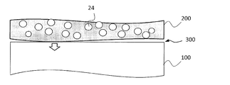
- FIG. 2 is a cross-sectional view schematically showing a state after a paste coating film 200 is formed on the surface of an RTB-based sintered magnet 100 and a drying process is performed. It is sectional drawing which shows the coating film 200 after performing a binder removal process. It is sectional drawing which shows the state of the coating film 200 after hold
- FIG. 3 is a cross-sectional view schematically showing a state in which heat treatment has progressed and metal in the coating film 200 has diffused from the surface of the RTB-based sintered magnet 100 into the magnet. It is sectional drawing which shows typically the part in which peeling of the coating film 200 produced in the middle of heat processing.
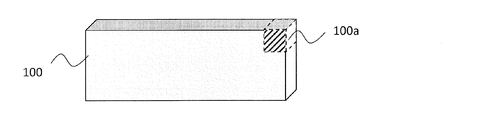
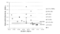
- FIG. 3 is a perspective view showing the position of a magnet piece cut out from an RTB-based sintered magnet 100 with broken lines in order to measure magnet characteristics. It is the graph which showed the ratio of the mixed powder of Table 2, and the residual C amount (what subtracted mixed powder containing C amount) of Table 3 according to the kind of binder and coupling agent.
- the binder in the paste is indispensable from the viewpoint of improving the application efficiency and making the application amount uniform.
- the components in the binder mainly carbon (hereinafter simply referred to as “C”), are not necessary for improving the magnetic properties by diffusion of the metal element.
- C is an impurity, and if contained in the magnet, it adversely affects the magnetic properties. For this reason, as long as the paste can be applied efficiently and uniformly, the role of the binder is completed, and it is important that the binder is removed as completely as possible in the heat treatment process.
- the present inventor has intensively studied in order to solve the problem that the coating film for metal element diffusion is peeled off during the heat treatment as described above, and the diffusion component in the coating film is not sufficiently diffused in the magnet.
- the coating film is peeled off by intentionally leaving a binder component, that is, C having an appropriate concentration in the coating film in a certain amount even during the diffusion heat treatment after completion of the binder removal.
- the inventors have found that it can be suppressed or prevented and have come up with the present invention.
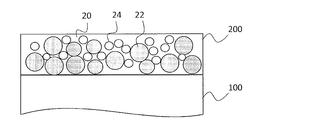
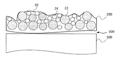
- FIG. 1A is a sectional view schematically showing a state after a paste coating film 200 is formed on the surface of an RTB-based sintered magnet 100 and a drying process is performed.
- a coating film (dry film) 200 a large number of metal powder particles 22 and metal compound powder particles 24 exist in the resin binder 20 that spreads in a film shape along the surface of the RTB-based sintered magnet 100.
- the coating film 200 immediately after application has an appropriate viscosity that is easy to apply and still maintains sufficient fluidity, but the fluidity is lost by performing the drying process.
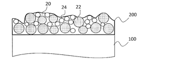
- FIG. 1B shows a cross section of the coating film 200 after performing the binder removal process at the temperature T1. Although most of the resin binder 20 of the coating film 200 is lost due to thermal decomposition or evaporation due to the binder removal process, the metal powder particles 22 and the metal compound powder particles 24 in the coating film (dry film) 200 are retained by the remaining portion. Is done. The coating film (dry film) 200 is adhered or fixed to the surface of the RTB-based sintered magnet 100.
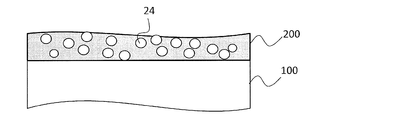
- FIG. 1C shows the state of the coating film 200 after heat treatment at a temperature (T3) exceeding the melting point (T2) of the metal powder particles 22.
- T3 a temperature exceeding the melting point of the metal powder particles 22.
- the coating film 200 When the coating film 200 is peeled off, the coating film 200 is warped in the vicinity of the temperature T2, and peeling starts to occur.
- the coating film 200 When the coating film 200 is formed on, for example, the upper surface of the RTB-based sintered magnet, the coating film 200 that starts to warp near the temperature T2 is softened in the process in which the heat treatment temperature further rises and reaches the temperature T3. Then, it may happen that it naturally adheres again to the upper surface of the RTB-based sintered magnet.
- the coating film 200 when the coating film 200 is formed on the side surface of the RTB-based sintered magnet, the coating film 200 that starts to warp near the temperature T2 adheres again to the side surface of the RTB-based sintered magnet. There is nothing.
- the coating film 200 when the coating film 200 is formed on the lower surface of the RTB-based sintered magnet, when the RTB-based sintered magnet is supported on a flat surface, the RTB When the space is present below the RTB-based sintered magnet, such as when supported by a rod-like or mesh-like support member, although warpage and peeling are not likely to occur due to the weight of the sintered magnet, Part of the film will peel off and will not adhere again.
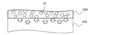
- the heat treatment proceeds at the temperature (T3), and the metal in the coating film 200 (for example, M derived from the RLM alloy that is metal powder particles or RH derived from the RH compound that is metal compound powder particles) is RT— A mode that it has diffused from the surface of B system sintered magnet 100 to the inside of a magnet is shown typically. At this time, rare earth elements diffuse from the inside of the RTB-based sintered magnet 100 to the surface, and mutual diffusion occurs. In this way, the metal component in the coating film can be diffused into the RTB-based sintered magnet by performing a heat treatment on the RTB-based sintered magnet having the coating film formed on the surface. It becomes possible.
- FIG. 2 is a cross-sectional view schematically showing a part where the coating film 200 has been peeled off during the heat treatment.
- FIG. 3 schematically shows the state of the heat treatment temperature T3 in the portion where the coating film 200 is peeled off.
- FIGS. 2 and 3 when peeling occurs in the coating film 200, a gap is generated between the coating film 200 and the RTB-based sintered magnet 100, so that the coating film 200 is included.
- the metal component cannot be uniformly diffused into the RTB-based sintered magnet 100.
- a method for producing a rare earth-based sintered magnet in a non-limiting exemplary embodiment of the present disclosure includes a step of preparing an RTB-based sintered magnet, and a paste coating film including a mixed powder and a resin binder Forming on the surface of the RTB-based sintered magnet.
- This mixed powder is a powder in which the metal powder and the metal compound powder are mixed. Note that the “metal” of the metal powder does not have to be composed of one kind of metal element, and may be “metal alloy”.
- the metal component in the coating film is converted to R— by performing heat treatment on the RTB based sintered magnet having the coating film formed on the surface. And a step of diffusing inside the TB sintered magnet.
- the coating film contains carbon (residual C) remaining after the heat treatment step.
- the value obtained by subtracting the carbon content before heat treatment of the mixed powder contained in the paste from the carbon content (residual C amount) remaining in the coating film after the heat treatment is 0 for the entire coating film after the heat treatment.
- the carbon content of the coating film before the heat treatment is adjusted so as to be in the range of 0.07 mass% or more and 0.50 mass% or less.
- the value obtained by subtracting the carbon content before heat treatment of the mixed powder contained in the paste from the carbon content (residual C amount) remaining in the coating film after heat treatment is the value of the coating film after heat treatment. It exists in the range of 0.07 mass% or more and 0.50 mass% or less of the whole.
- the content (mass) of carbon remaining in the coating film after the heat treatment step is X
- the carbon content (mass) of the mixed powder contained in the paste before the heat treatment is Y
- Z is the total mass of the coating film after the heat treatment.
- the carbon content of the paste before the heat treatment depends on the amount of carbon contained in a composition such as a mixed powder and a resin binder constituting the paste.
- part of the carbon in the paste disappears due to thermal decomposition or evaporation due to the heat treatment, so that the amount of carbon contained in the coating film after the heat treatment may vary depending on the temperature and time of the heat treatment.
- the coating film is peeled only when (XY) / Z finally obtained is in a narrow range of 0.07% by mass or more and 0.50% by mass or less. It was found that it was prevented.
- a paste coating film is formed on the surface of an actual rare earth sintered magnet, the mixed powder reacts with the rare earth sintered magnet during the heat treatment, so it is difficult to correctly measure the values of X and Z. possible. Therefore, according to the present disclosure, when determining the value of (XY) / Z, a paste coating film is formed on the surface of a substance having low reactivity with the mixed powder, and after performing a predetermined heat treatment, Measure X and Z.
- the substance having low reactivity with the mixed powder is optional, but for example, a resin film such as PET (polyethylene terephthalate) having a thickness of about 0.05 mm to 0.2 mm can be used.
- Paste preparation As described above, the carbon content (mass) X remaining in the coating film after the heat treatment step, the carbon content (mass) Y before heat treatment of the mixed powder contained in the paste, and the heat treatment
- the binder type, the mixed powder, and the like so that the index value (XY) / Z expressed by the total mass Z of the coating film later falls within the range of 0.07% by mass to 0.50% by mass.
- the amount of coupling, the type of coupling agent to be added, the amount added, etc. are adjusted.
- the paste may be mixed with an organic solvent or water to adjust the viscosity of the paste. Since C in the organic solvent is almost completely evaporated and removed when the coating film is dried, the amount of C is not affected.
- the type of binder and the type of coupling agent that can be added as necessary are not particularly limited.
- PVA or ethyl cellulose can be used as the binder, and a silane coupling agent, titanate coupling agent, aluminate coupling agent, or the like can be used as the coupling agent.
- the blending ratio of the mixed powder, binder, and coupling agent can be adjusted so that the mixed powder occupies 95 to 99% of the total in the dry film state.
- the addition amount of the coupling agent can be blended so as to be 0 to 85% with respect to the resin as the binder.
- (XY) / Z is not always included in the range of 0.07% by mass or more and 0.50% by mass or less. This is because the amount of residual C varies depending on the type of binder and coupling agent. Therefore, it is necessary to obtain (XY) / Z by measuring the amount of residual C after heat treatment by changing the kind and blending ratio of the mixed powder, binder, and coupling agent that actually constitute the paste. Then, the paste conditions may be selected such that the obtained (XY) / Z is in the range of 0.07 mass% to 0.50 mass%.
- the spatial distribution and concentration of components in the coating film on the surface of the RTB-based sintered magnet may change during the heat treatment. This is because the metal component in the coating film is affected by diffusion into the RTB-based sintered magnet. As a result, it has been found that each component does not necessarily exist uniformly in the thickness direction in the coating film. Specifically, the carbon concentration in the coating film tends to be higher in the surface layer portion on the opposite side from the magnet surface than on the side in contact with the magnet surface. Further, when peeling does not occur in the coating film, it is extremely difficult to measure the amount of C in the coating film by removing only the coating film from the surface of the RTB-based sintered magnet. For this reason, it is difficult to accurately measure the amount of residual C in the coating film on the surface of the RTB-based sintered magnet.
- a paste is applied on a resin film and dried to obtain a dry film (a film obtained by drying the paste coating film). And after heat-processing this dry film
- the amount of residual C can be determined by measuring at the end of heat treatment.
- the amount of C in the dry film hardly changes from the start of heat treatment (when the magnet temperature reaches the heat treatment temperature) to the end of heat treatment.
- the amount of C in the dry film hardly changes even after the binder removal treatment performed before the heat treatment is completed until the heat treatment is completed. Therefore, even if the amount of C in the dry film is measured during these periods, the amount of residual C at the end of the heat treatment can be accurately estimated.
- the carbon content (residual C amount) remaining in the coating film even after the heat treatment step is determined at an arbitrary timing in the period from the end of the binder removal treatment before the heat treatment to the end of the heat treatment for diffusion. Can be measured.
- the value of “residual carbon content” (residual carbon content) after the heat treatment step is clearly defined, and therefore the “residual carbon content” value does not react with the paste. It is defined as the carbon content measured for a film that has been subjected to the heat treatment under the same conditions as in the heat treatment step after peeling off the paste film (paste dry film) from the member.
- the mixed powder contained in the paste is a powder in a state where the metal powder and the metal compound powder are mixed.
- the content of the mixed powder varies depending on what metal element is introduced into the RTB-based sintered magnet.
- a specific example of the mixed powder will be described below by taking an example in which the heavy rare earth element RH is diffused into the RTB-based sintered magnet.
- RLM alloy powder that functions as a diffusion aid can be used.
- RL a light rare earth element having a high effect of reducing the RH compound is suitable. Further, RL is also sometimes M also has the effect of diffused into the magnet to improve the H cJ, tends to reduce the spread easily B r to the main phase crystal grains inside the element should be avoided. From the viewpoint of high effect of reducing this RH compound and difficulty in diffusing into the main phase crystal grains, RL is one or more selected from Nd and / or Pr, M is selected from Cu, Fe, Ga, Co, Ni, and Al.
- the RLM alloy uses an alloy containing RL at 50 atomic% or more and having a melting point equal to or lower than the heat treatment temperature.
- Such an RLM alloy efficiently reduces the RH compound during the heat treatment, and the RH reduced at a higher rate diffuses into the RTB-based sintered magnet so that the RTB system can be efficiently used even in a small amount.
- the H cJ of the sintered magnet can be improved.
- the particle size of the RLM alloy powder is preferably 500 ⁇ m or less.
- RH is Dy and / or Tb
- the RH compound is one or more selected from RH fluoride, RH oxide, and RH oxyfluoride
- RH fluoride is preferable because it is easily reduced by the RLM alloy and has a large effect of improving HcJ .
- the particle size of the RH compound powder is preferably 100 ⁇ m or less.
- the RH oxyfluoride in the present invention may be included in the RH fluoride as an intermediate substance in the production process of the RH fluoride.
- RH diffuses into the RTB -based sintered magnet, and H cJ can be greatly improved with a small amount of RH.
- a powder (third powder) other than the powder of the RLM alloy and the RH compound is present on the surface of the RTB-based sintered magnet. Care must be taken not to inhibit diffusion of RH in the RH compound into the RTB-based sintered magnet.
- the mass ratio of the “RLM alloy and RH compound” powder in the entire powder existing on the surface of the RTB-based sintered magnet is desirably 70% or more.
- RTB-based sintered magnet base material An RTB-based sintered magnet base material to be diffused of the heavy rare earth element RH is prepared.
- an RTB-based sintered magnet that is a target of diffusion of the heavy rare earth element RH may be strictly referred to as an RTB-based sintered magnet base material.
- the term “RTB-based sintered magnet” includes such “RTB-based sintered magnet base material”.
- a known material can be used, for example, having the following composition.
- Rare earth element R 12 to 17 atomic% B (a part of B (boron) may be substituted with C (carbon)): 5 to 8 atomic%
- Additive element M ′ selected from the group consisting of Al, Ti, V, Cr, Mn, Ni, Cu, Zn, Ga, Zr, Nb, Mo, Ag, In, Sn, Hf, Ta, W, Pb, and Bi At least one kind): 0 to 2 atomic% T (which is a transition metal element mainly containing Fe and may contain Co) and inevitable impurities: the balance
- the rare earth element R is mainly composed of at least one kind selected from light rare earth elements RL (Nd, Pr) Element), but may contain heavy rare earth elements. In addition, when a heavy rare earth element is contained, it is preferable that at least one of Dy and Tb is included.
- the RTB-based sintered magnet base material having the above composition is manufactured by an arbitrary manufacturing method.
- Examples of a method for forming a coating film on the surface of the RTB-based sintered magnet may include a coating method (printing method), a dipping method, a spray method, and the like.
- the thickness of the coating film can be set in the range of 0.05 to 0.5 mm, for example.
- the amount of RH element in the powder present on the surface of the RTB-based sintered magnet is preferably 0.03 to 0.35 mg, preferably 0.05 to 0.25 mg per 1 mm 2 of the magnet surface. More preferably.
- the thickness of the coating film can be adjusted to realize such a value.
- the coating film is held at a temperature of, for example, 80 to 100 ° C. for 30 minutes to 3 hours and dried.
- the coating film is heat-treated at a temperature (T1) of 350 to 450 ° C. for 1 to 4 hours, for example.
- T1 a temperature of 350 to 450 ° C. for 1 to 4 hours, for example.
- a heat treatment is performed at a temperature (T3) exceeding the melting point (T2) of the metal powder particles contained in the coating film, for example, 500 to 1000 ° C. Are diffused from the surface of the RTB-based sintered magnet to the inside.
- the heat treatment can be performed in a state in which the powder of the RLM alloy and the powder of the RH compound are present on the surface of the RTB-based sintered magnet. Since the RLM alloy powder melts after the start of the heat treatment, it is not necessary for the RLM alloy to always maintain a “powder” state during the heat treatment.
- the atmosphere for the heat treatment is preferably a vacuum or an inert gas atmosphere.
- the surface of the coating film is ground to a depth of, for example, about 50 to 500 ⁇ m, and the coating film and the surface layer of the RTB-based sintered magnet are removed.
- Example 1 -Measurement of C amount Mixed powder, binder, coupling agent, and solvent were blended under the conditions shown in Table 1 below to prepare a paste. These blending ratios are shown as mass% (mass%) in Table 1.
- the mixed powder in this example was prepared by mixing RLM alloy powder and RH fluoride powder at a mass ratio of 60:40.
- the RLM alloy powder is composed of Nd 70 Cu 30 alloy particles having a particle size of 150 ⁇ m or less prepared by a centrifugal atomization method.
- the RH fluoride powder is composed of TbF 3 particles having a particle size of 100 ⁇ m or less.
- the binder used in this example is EC (ethyl cellulose) or PVA (polyvinyl alcohol).
- the coupling agent is an epoxy SC (silane coupling agent), an amino SC, an amino TC (titanate coupling agent), a vinyl SC, an alkyl SC, or a methacrylic SC.
- the solvent was ethanol when the binder was ethyl cellulose, and pure water when the binder was polyvinyl alcohol.
- the prepared paste was applied to a PET film having a thickness of 70 ⁇ m and dried at 90 ° C. for 1 hour.
- the paste after drying is referred to as “dry film”.
- Table 2 shows the ratio of each component in the dried film obtained by calculation.
- the dried film was placed on a Mo plate, heated from room temperature to 400 ° C. at 10 ° C./min in a heat treatment apparatus, and heat treated at 400 ° C. for 2 hours. Thereafter, the temperature was further raised to 900 ° C. at 10 ° C./min, followed by heat treatment at 900 ° C. for 8 hours.
- These heat treatment conditions are set to be the same as the heat treatment conditions performed after the paste is actually applied to the surface of the RTB-based sintered magnet to form a coating film.
- the amount of residual C in the sample obtained by cooling after the heat treatment was measured with a high-frequency induction heating carbon analyzer (Horiba, Ltd .: EMIA-920V2).
- Table 3 shows the amount of residual C in the sample, the amount of C contained in the mixed powder before the heat treatment, and the difference between them.
- a B-type sintered magnet was produced. This was machined to obtain an RTB-based sintered magnet base material of 5.7 mm ⁇ 15.6 mm ⁇ 70.2 mm. Magnetic properties of the obtained R-T-B based sintered magnet base material where a measured by B-H tracer, H cJ is 1052kA / m, B r was 1.45 T. The amount of impurities in the RTB-based sintered magnet base material was measured with a gas analyzer, and as a result, oxygen was 740 ppm, nitrogen was 490 ppm, and carbon was 880 ppm.
- a paste prepared with the types and blending ratios shown in Table 1 was applied to the surface of the above-mentioned RTB-based sintered magnet base material having a size of 15.6 mm ⁇ 70.2 mm by screen printing.
- the coating amount was adjusted so that the amount of Tb per mm 2 was 0.07 mg. After application, it was dried at 90 ° C. for 1 hour.
- the paste was applied to the opposite surface of the RTB-based sintered magnet base material and dried.
- An RTB-based sintered magnet having a paste coating film (dried film) formed on both sides was erected so that the coating surface was vertical. Specifically, after raising the temperature from room temperature to 400 ° C. at 10 ° C./min, heat treatment is performed at 400 ° C. for 2 hours, and further, the temperature is raised to 900 ° C. at 10 ° C./min, and then at 900 ° C. for 8 hours. The heat treatment was performed.
- FIG. 5 is a graph showing the difference between the ratio of the mixed powder in Table 2 and the “residual C amount ⁇ mixed powder-containing C amount” in Table 3 for each type of binder and coupling agent. This figure shows that when the value of “residual C content ⁇ mixed powder content C content” is 0.07% by mass or more, there is no coating film peeling after heat treatment, and when it is less than 0.07% by mass, coating film peeling occurs. It is shown that. Regardless of the type of binder and coupling agent, “residual C amount—mixed powder-containing C amount” tends to decrease as the proportion of the mixed powder increases.
- residual C amount—mixed powder-containing C amount varies depending on the type of binder or coupling agent and the blending ratio thereof. For example, when the ratio of the mixed powder is 98.78% by mass or 98.28% by mass, the same ratio of the mixed powder, that is, even when the same amount of the binder and the coupling agent is used, the binder and the coupling are used. Depending on the difference in the agent, peeling of the coating film may or may not occur.
- the binder when the value indicated by ⁇ , the binder is ethyl cellulose and the coupling agent is an epoxy silane coupling agent, or the value indicated by ⁇ , the binder is PVA and the coupling agent is not present, the same resin Even if a coupling agent is used, "residual C amount-mixed powder-containing C amount" depending on the difference in the ratio of the mixed powder (that is, the difference in the amount of binder and coupling agent used) and the blending ratio of the binder and the coupling agent.
- the coating film may or may not peel off. As can be seen from ⁇ and ⁇ (the binder is ethyl cellulose and no coupling agent), the presence or absence of the coupling agent is the same, and the coating film may or may not peel off with or without the coupling agent.
- the presence or absence of peeling after the heat treatment is not determined by the ratio of the mixed powder, the type of the binder or the coupling agent, or the blending ratio, but the “residual C amount-mixed powder after the heat treatment determined by the combination thereof” It turns out that it depends on "the amount of contained C”.
- the present invention has been completed based on such findings.
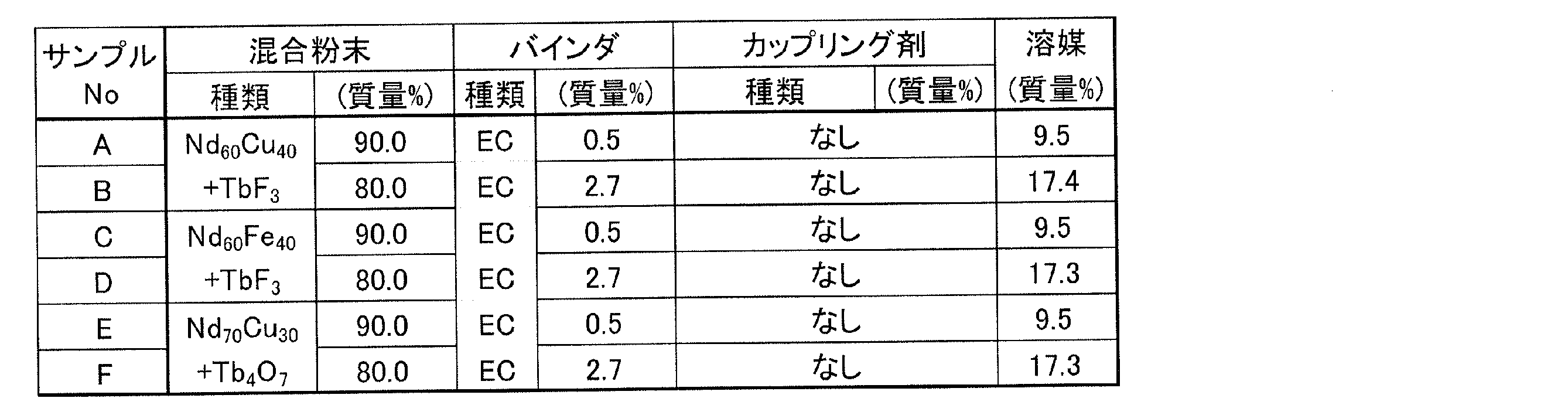
- Example 2 The same evaluation as in Example 1 was performed using the mixed powder, binder, and coupling agent shown in Samples A to F in Table 5 below. The prepared paste was applied to a PET film and dried at 90 ° C. for 1 hour. Table 6 shows the ratio of each component in the dry film obtained by calculation.
- the present invention can improve the H cJ of an RTB -based sintered magnet with less heavy rare earth element RH, and therefore can be used for the production of a rare-earth sintered magnet that requires a high H cJ .
- the present invention can also be widely applied to techniques that require diffusion of metal elements other than the heavy rare earth element RH from the surface to the rare earth sintered magnet.
- Metal powder particles Metal compound powder particles 100 RTB-based sintered magnet 200 Coating film
Landscapes
- Engineering & Computer Science (AREA)
- Chemical & Material Sciences (AREA)
- Power Engineering (AREA)
- Mechanical Engineering (AREA)
- Materials Engineering (AREA)
- Metallurgy (AREA)
- Organic Chemistry (AREA)
- Manufacturing & Machinery (AREA)
- Crystallography & Structural Chemistry (AREA)
- Inorganic Chemistry (AREA)
- Chemical Kinetics & Catalysis (AREA)
- Hard Magnetic Materials (AREA)
- Manufacturing Cores, Coils, And Magnets (AREA)
- Powder Metallurgy (AREA)
Abstract
金属粉末22および金属化合物粉末24が混合された混合粉末と樹脂バインダ20とを含むペーストの塗布膜200をR-T-B系焼結磁石100の表面に形成する。次に、熱処理を行うことによって塗布膜200中の金属成分を焼結磁石100の内部に拡散させる。塗布膜200は、熱処理工程後にも残存する炭素を含有し、かつ、残存する炭素の含有量から、ペーストに含まれていた混合粉末の熱処理前における炭素含有量を差し引いた値が、熱処理後における塗布膜200の全体の0.07質量%以上0.50質量%以下の範囲になるように、熱処理前における塗布膜200の炭素含有量が調整されている。
Description
本開示は、希土類系焼結磁石の製造方法に関する。
R2T14B型化合物を主相とするR-T-B系焼結磁石は、永久磁石の中で最も高性能な磁石として知られており、ハードディスクドライブのボイスコイルモータ(VCM)や、ハイブリッド車搭載用モータ等の各種モータや家電製品等に使用されている。
R-T-B系焼結磁石は、高温で固有保磁力HcJ(以下、単に「HcJ」と表記する)が低下するため、不可逆熱減磁が起こる。不可逆熱減磁を回避するため、モータ用等に使用する場合、高温下でも高いHcJを維持することが要求されている。
R-T-B系焼結磁石は、R2T14B型化合物相中のRの一部を重希土類元素RH(Dy、Tb)で置換すると、HcJが向上することが知られている。高温で高いHcJを得るためには、R-T-B系焼結磁石中に重希土類元素RHを多く添加することが有効である。しかし、R-T-B系焼結磁石において、Rとして軽希土類元素RL(Nd、Pr)を重希土類元素RHで置換すると、HcJが向上する一方、残留磁束密度Br(以下、単に「Br」と表記する)が低下してしまうという問題がある。また、重希土類元素RHは希少資源であるため、その使用量を削減することが求められている。
そこで、近年、Brを低下させないように、より少ない重希土類元素RHによってR-T-B系焼結磁石のHcJを向上させることが検討されている。例えば、重希土類元素RHのフッ化物もしくは酸化物、各種の金属MまたはM合金を、それぞれ、単独または混合して焼結磁石の表面に存在させ、その状態で熱処理することにより、HcJ上昇に寄与する重希土類元素RHを磁石内に拡散させることが提案されている。
特許文献1は、R酸化物、Rフッ化物、R酸フッ化物の粉末を用いることを開示している。
特許文献2は、RM(MはAl,Cu,Zn,Ga などから選ばれる1種以上)合金の粉末を用いることを開示している。
特許文献3、4は、RM合金(MはAl,Cu,Zn,Gaなどから選ばれる1種以上)、M1M2合金(M1M2はAl,Cu,Zn,Gaなどから選ばれる1種以上)、およびRH酸化物の混合粉末を用いることにより、熱処理時にRM合金などによってRH酸化物を部分的に還元し、重希土類元素RHを磁石内に導入することが可能であることを開示している。
上記の特許文献に開示されている方法では、粉末を焼結磁石表面に存在させるため、典型的には、粉末を水または有機溶剤に分散させたスラリーを作製し、このスラリー中に焼結磁石を浸漬した後に乾燥を行う。また、このようなスラリーをスプレーによって塗布する方法も用いられ得る。
本発明者は、これらの粉末をバインダと混合したペーストを焼結磁石の表面に塗布する方法について検討したところ、熱処理の過程で塗布膜が焼結磁石表面から剥がれ、剥がれた部分に含まれる粉末中元素は焼結磁石内部に十分には拡散されないという問題が生じ得ることがわかった。
本開示の実施形態は、塗布膜に含まれる粉末粒子から所望の元素を再現性良く塗布対象物内に拡散させることを可能にする。
本開示による希土類系焼結磁石の製造方法は、R-T-B系焼結磁石を用意する工程と、金属粉末および金属化合物粉末が混合された混合粉末と樹脂バインダとを含むペーストの塗布膜を前記R-T-B系焼結磁石の表面に形成する工程と、前記塗布膜が前記表面に形成された前記R-T-B系焼結磁石に対する熱処理を行うことによって前記塗布膜中の金属成分を前記R-T-B系焼結磁石の内部に拡散させる工程とを含み、前記塗布膜は、前記熱処理工程後にも残存する炭素を含有し、かつ、前記残存する炭素の含有量から、前記ペーストに含まれていた混合粉末の前記熱処理前における炭素含有量を差し引いた値が、前記熱処理後における前記塗布膜の全体の0.07質量%以上0.50質量%以下の範囲になるように、前記熱処理前における前記塗布膜の炭素含有量が調整されている。
ある実施形態において、前記熱処理前における乾燥した塗布膜全体に対する前記混合粉末の割合は95質量%以上99質量%以下である。
ある実施形態において、前記混合粉末は、RLM合金(RLはNdおよび/またはPr、MはCu、Fe、Ga、Co、Niから選ばれる1種以上)の金属粉末と、RHフッ化物(RHはDyおよび/またはTb)、RH酸フッ化物、およびRH酸化物の少なくとも1つの金属化合物粉末とを含有する。
ある実施形態において、前記RLM合金の粉末は、前記混合粉末の全体の50質量%以上96質量%以下である。
ある実施形態において、前記ペーストはカップリング剤を含有する。
前記残存する炭素の含有量は、前記ペーストとは反応しない部材上で乾燥された前記ペーストの膜を前記部材から剥がした後前記熱処理工程と同一の条件で熱処理した膜を対象として測定された炭素含有量であると定義される。
本開示の実施形態によると、粉末とバインダとを混合したペーストの塗布膜が、熱処理工程によって剥がれることが防止されるため、塗布膜中の粉末から所望の元素を対象物に拡散することが歩留まり良く実現し得る。ある実施形態の態様では、粉末ペーストの塗布膜が焼結磁石表面から剥がれることが抑制または防止されるため、粉末中の所望の金属元素が歩留まり良く焼結磁石内に拡散し、HcJを向上させる効果を得ることができる。
ペースト塗布法による塗布・拡散において、ペースト中のバインダは、塗布の作業効率を高め、塗布量を均一化するという観点から必須である。しかし、バインダ中の成分、主に炭素(以下、単に「C」と表記する)は、金属元素の拡散による磁気特性向上には不要である。また、R-T-B系焼結磁石において、Cは不純物であり、磁石中に含まれた場合は磁気特性に悪影響を及ぼす。このため、ペーストを効率よく均一に塗布さえできれば、バインダの役割は終了し、熱処理工程においては、できるだけ完全に脱バインダが行われることが重要である、というのがこれまでの常識であった。
本発明者は、前述のように熱処理の過程で金属元素拡散のための塗布膜が剥がれてしまい、塗布膜中の拡散成分が磁石中に十分拡散されないという問題を解決するために鋭意検討した。その結果、これまでの常識に反して、脱バインダ完了後の拡散熱処理中も塗布膜中にある程度の量でバインダ成分、すなわち適切な濃度のCを意図的に残留させることによって塗布膜の剥がれを抑制または防止できることを見出し、本発明を想到するに至った。
まず、混合粉末と樹脂バインダとを含むペーストの塗布膜をR-T-B系焼結磁石の表面に形成した後、この塗布膜が乾燥および熱処理を経てどのように変化していくかを説明する。
図1Aは、ペーストの塗布膜200をR-T-B系焼結磁石100の表面に形成し、乾燥工程を行った後の状態を模式的に示す断面図である。塗布膜(乾燥膜)200では、R-T-B系焼結磁石100の表面に沿って膜状に広がる樹脂バインダ20中に多数の金属粉末粒子22および金属化合物粉末粒子24が存在している。塗布直後の塗布膜200は、塗布しやすい適切な粘度を持ち、十分な流動性をまだ保持しているが、乾燥工程を行うことより、流動性はなくなる。
図1Bは、温度T1で脱バインダ工程を行った後の塗布膜200の断面を示している。脱バインダ工程により、塗布膜200の樹脂バインダ20の大部分は熱分解や蒸発などによって失われるが、残存部分によって塗布膜(乾燥膜)200中の金属粉末粒子22および金属化合物粉末粒子24が保持される。塗布膜(乾燥膜)200は、R-T-B系焼結磁石100の表面に粘着または固着している。
図1Cは、金属粉末粒子22の融点(T2)を超える温度(T3)で熱処理を行った後の塗布膜200の状態を示している。この状態では、金属粉末粒子22は溶融し、少なくとも一部が膜状に広がって金属化合物粉末粒子24と接触していると推定される。塗布膜200は、樹脂バインダ20の残存物、金属粉末粒子22の溶融物、および金属化合物粉末粒子24が混在した膜の状態でR-T-B系焼結磁石100の表面に固着している。
塗布膜200が剥がれる場合は、温度T2の付近で塗布膜200が反り、剥がれが生じ始める。塗布膜200がR-T-B系焼結磁石の例えば上面に形成されている場合、温度T2付近で反り始めた塗布膜200は、熱処理温度が更に上昇して温度T3に達する過程で、軟化して再びR-T-B系焼結磁石の上面に自然に付着することが起こり得る。しかし、塗布膜200がR-T-B系焼結磁石の側面に形成されている場合、温度T2付近で反り始めた塗布膜200が再びR-T-B系焼結磁石の側面に付着することはない。また、塗布膜200がR-T-B系焼結磁石の下面に形成されている場合、フラットな面でR-T-B系焼結磁石が支持されている場合は、R-T-B系焼結磁石の自重によって反りや剥がれは生じにくいものの、棒状や網目状の支持部材で支持される場合など、R-T-B系焼結磁石の下方に空間が存在する場合には、その部分の膜が剥がれてしまい、再び付着することは無い。
図1Dは、温度(T3)で熱処理が進行し、塗布膜200内の金属(例えば金属粉末粒子であるRLM合金由来のMや金属化合物粉末粒子であるRH化合物由来のRH)がR-T-B系焼結磁石100の表面から磁石内部に拡散している様子を模式的に示している。このとき、R-T-B系焼結磁石100の内部から表面に希土類元素が拡散し、相互拡散が生じている。このように、塗布膜が表面に形成されたR-T-B系焼結磁石に対する熱処理を行うことによって塗布膜中の金属成分をR-T-B系焼結磁石の内部に拡散させることが可能になる。
図2は、熱処理の途中に塗布膜200の剥がれが生じた部分を模式的に示す断面図である。図3は、塗布膜200の剥がれが生じた部分における熱処理温度T3の状態を模式的に示している。図2および図3に示されるように、塗布膜200に剥がれが生じると、塗布膜200とR-T-B系焼結磁石100との間に隙間が発生するため、塗布膜200に含まれる金属成分をR-T-B系焼結磁石100内に均一に拡散させることができなくなる。
本開示の限定的ではない例示的な実施形態における希土類系焼結磁石の製造方法は、R-T-B系焼結磁石を用意する工程と、混合粉末と樹脂バインダとを含むペーストの塗布膜を前記R-T-B系焼結磁石の表面に形成する工程とを含む。この混合粉末は、金属粉末と金属化合物粉末とが混合された状態にある粉末である。なお、金属粉末の「金属」は、1種類の金属元素から構成されている必要は無く、「合金(metal alloy)」であってもよい。
更に、本実施形態における希土類系焼結磁石の製造方法は、上述の塗布膜が表面に形成されたR-T-B系焼結磁石に対する熱処理を行うことによって塗布膜中の金属成分をR-T-B系焼結磁石の内部に拡散させる工程を含む。
本開示の実施形態において、塗布膜は、熱処理工程後にも残存する炭素(残留C)を含有する。この熱処理後の塗布膜に残存する炭素の含有量(残留C量)から、ペーストに含まれていた混合粉末の熱処理前における炭素含有量を差し引いた値が、熱処理後における塗布膜の全体の0.07質量%以上0.50質量%以下の範囲になるように、熱処理前における塗布膜の炭素含有量が調整されている。言い換えると、熱処理後の塗布膜に残存する炭素の含有量(残留C量)から、ペーストに含まれていた混合粉末の熱処理前における炭素含有量を差し引いた値は、熱処理後において、塗布膜の全体の0.07質量%以上0.50質量%以下の範囲にある。
ここで、熱処理工程後の塗布膜中に残存する炭素の含有量(質量)をXとし、ペーストに含まれていた混合粉末の熱処理前における炭素含有量(質量)をYとする。また、熱処理後における塗布膜の全体の質量をZとする。熱処理前におけるペーストの炭素含有量は、ペーストを構成する混合粉末および樹脂バインダなどの組成物が含有する炭素の量に依存する。また、熱処理により、ペースト中の炭素の一部が熱分解や蒸発などによって消失するため、熱処理の温度および時間に応じて、熱処理後の塗布膜が含有する炭素の量は異なり得る。しかしながら、本発明者が検討した結果、最終的に得られる(X-Y)/Zが0.07質量%以上0.50質量%以下という狭い範囲内にある場合に限り、塗布膜の剥がれが防止されることがわかった。これは、所定の条件範囲で熱処理を行う場合、(X-Y)/Zの値によって塗布膜の挙動を予想できることを意味し、(X-Y)/Zを指標として、ペーストの組成を調整して塗布膜の剥がれを防止することが可能になる。
なお、実際の希土類系焼結磁石の表面にペーストの塗布膜を形成した場合、熱処理中に混合粉末が希土類系焼結磁石と反応するため、XおよびZの値を正しく測定することが困難であり得る。このため、本開示によれば、(X-Y)/Zの値を求めるとき、混合粉末との反応性が低い物質の表面にペーストの塗布膜を形成し、所定の熱処理を行った後、XおよびZを測定する。混合粉末との反応性が低い物質は、任意であるが、例えば、厚さが0.05mm~0.2mm程度のPET(ポリエチレンテレフタラート)などの樹脂フィルムが用いられ得る。
以下、本実施形態における希土類系焼結磁石の製造方法の各工程を説明する。
(1)ペースト作製
前述したように、熱処理工程後の塗布膜中に残存する炭素の含有量(質量)X、ペーストに含まれていた混合粉末の熱処理前における炭素含有量(質量)Y、熱処理後における塗布膜の全体の質量Zによって表現される指標値(X-Y)/Zが0.07質量%以上0.50質量%以下の範囲内に入るように、バインダの種類、混合粉末との配合量、添加するカップリング剤の種類、添加量などを調整する。作業性向上の為ペーストに有機溶剤や水などの溶媒を混合してペーストの粘度を調整してもよい。有機溶剤中のCは塗布膜を乾燥する際にほぼ完全に蒸発して除去されるため、前記C量には影響しない。
前述したように、熱処理工程後の塗布膜中に残存する炭素の含有量(質量)X、ペーストに含まれていた混合粉末の熱処理前における炭素含有量(質量)Y、熱処理後における塗布膜の全体の質量Zによって表現される指標値(X-Y)/Zが0.07質量%以上0.50質量%以下の範囲内に入るように、バインダの種類、混合粉末との配合量、添加するカップリング剤の種類、添加量などを調整する。作業性向上の為ペーストに有機溶剤や水などの溶媒を混合してペーストの粘度を調整してもよい。有機溶剤中のCは塗布膜を乾燥する際にほぼ完全に蒸発して除去されるため、前記C量には影響しない。
(X-Y)/Zが0.07質量%未満であると、脱バインダ後から熱処理終了までの間に塗布膜の剥がれが生じ、塗布膜中の混合粉末が磁石に接しない状態となる。このため、これらが磁石内に十分拡散されず、HcJの向上が少なくなる。また(X-Y)/Zが0.50質量%を超えると、塗布膜中の混合粉末の割合が低くなり、十分にHcJを向上させるだけの混合粉末を熱処理前に磁石表面に保持できなくなる。
バインダの種類、および、必要に応じて添加され得るカップリング剤の種類は特に制限されない。例えば、バインダとしてはPVAやエチルセルロース、カップリング剤としては、シランカップリング剤、チタネート系カップリング剤、アルミネート系カップリング剤などが用いられ得る。
混合粉末、バインダ、およびカップリング剤の配合比は、乾燥膜の状態において、混合粉末が全体の95~99%を占めるように調整され得る。カップリング剤の添加量は、バインダとなる樹脂に対して0~85%となるように配合され得る。しかし、この配合比にすれば(X-Y)/Zが常に0.07質量%以上0.50質量%以下の範囲内に含まれるわけではない。バインダおよびカップリング剤の種類によって残留C量は異なるからである。このため、現実にペーストを構成する混合粉末、バインダ、およびカップリング剤の種類および配合比率を変化させ、熱処理後の残留C量を測定して(X-Y)/Zを求める必要がある。そして、求めた(X-Y)/Zが0.07質量%以上0.50質量%以下の範囲内になるようなペーストの条件を選択すればよい。
しかし、R-T-B系焼結磁石表面の塗布膜における成分の空間的分布および濃度は、熱処理の過程において、変化する可能性がある。これは、塗布膜中の金属成分がR-T-B系焼結磁石中に拡散する影響を受けるためである。その結果、必ずしも各成分が塗布膜内において厚さ方向に均一に存在していないことが分かっている。具体的には、塗布膜中の炭素濃度は、磁石表面に接する側よりも磁石表面からは反対側の表層部において高い傾向にあるようである。また、塗布膜に剥がれが生じない場合、塗布膜のみをR-T-B系焼結磁石表面からすべて剥がして塗布膜中のC量を測定することは極めて困難である。このため、R-T-B系焼結磁石表面の塗布膜中の残留C量を正確に測定することは難しい。
本開示の方法では、例えば樹脂フィルム上にペーストを塗布して乾燥させ、乾燥膜(ペーストの塗布膜が乾燥した膜)を得る。そして、この乾燥膜を熱処理した後、残留C量を測定する。そして、熱処理後の塗布膜に含まれる残留C量から、混合粉末中に含まれていたC量を減算した値が、上記の範囲内に含まれるようにペーストの構成を決定する。
残留C量は熱処理終了時に測定して決定することができる。しかし、本発明者らの実験によれば、熱処理開始時(磁石温度が熱処理温度に到達した時点)から熱処理終了時までの間で乾燥膜中のC量はほとんど変化しないことが確かめられている。さらには、熱処理前に行う脱バインダ処理終了後から熱処理終了時までの間でも、乾燥膜中のC量はほとんど変化しないことも確かめられている。したがって、これらの期間に乾燥膜中のC量を測定しても、熱処理終了時の残留C量を正確に推定することが可能である。
このように、熱処理工程後にも塗布膜に残存する炭素の含有量(残留C量)は、熱処理前に行う脱バインダ処理終了時から、拡散のための熱処理終了時までの期間の任意のタイミングで測定され得る。しかし、本開示では、「熱処理工程後にも塗布膜に残存する炭素の含有量(残留C量)」の値を明確に定義するため、「残留C量」の値は、ペーストとは反応しないシート上で乾燥されたペーストの膜(ペーストの乾燥膜)を前記部材から剥がした後前記熱処理工程と同一の条件で熱処理した膜を対象として測定された炭素含有量であると定義する。
ペーストに含まれる混合粉末は、金属粉末と金属化合物粉末とが混合された状態にある粉末である。この混合粉末の内容は、どのような金属元素をR-T-B系焼結磁石の内部に導入するかによって異なる。重希土類元素RHをR-T-B系焼結磁石内に拡散する場合を例にとり、混合粉末の具体例を以下に説明する。
[金属粉末]
拡散助剤として機能するRLM合金の粉末を用いることができる。RLとしてはRH化合物を還元する効果の高い軽希土類元素が適している。また、RLもMも磁石中に拡散してHcJを向上させる効果を持つ場合があるが、主相結晶粒内部にまで拡散しやすくBrを低下させやすい元素は避けるべきである。このRH化合物を還元する効果が高く、主相結晶粒内部に拡散しにくいという観点から、RLはNdおよび/またはPr、MはCu、Fe、Ga、Co、Ni、Alから選ばれる1種以上とする。中でもNd-Cu合金やNd-Fe合金を用いると、NdによるRH化合物の還元能力が効果的に発揮されるので好ましい。また、RLM合金はRLを50原子%以上含み、かつ、その融点が熱処理温度以下の合金を用いる。このようなRLM合金は、熱処理時にRH化合物を効率よく還元し、より高い割合で還元されたRHがR-T-B系焼結磁石中に拡散して少量でも効率よくR-T-B系焼結磁石のHcJを向上させることができる。RLM合金の粉末の粒度は500μm以下が好ましい。
拡散助剤として機能するRLM合金の粉末を用いることができる。RLとしてはRH化合物を還元する効果の高い軽希土類元素が適している。また、RLもMも磁石中に拡散してHcJを向上させる効果を持つ場合があるが、主相結晶粒内部にまで拡散しやすくBrを低下させやすい元素は避けるべきである。このRH化合物を還元する効果が高く、主相結晶粒内部に拡散しにくいという観点から、RLはNdおよび/またはPr、MはCu、Fe、Ga、Co、Ni、Alから選ばれる1種以上とする。中でもNd-Cu合金やNd-Fe合金を用いると、NdによるRH化合物の還元能力が効果的に発揮されるので好ましい。また、RLM合金はRLを50原子%以上含み、かつ、その融点が熱処理温度以下の合金を用いる。このようなRLM合金は、熱処理時にRH化合物を効率よく還元し、より高い割合で還元されたRHがR-T-B系焼結磁石中に拡散して少量でも効率よくR-T-B系焼結磁石のHcJを向上させることができる。RLM合金の粉末の粒度は500μm以下が好ましい。
[金属化合物粉末]
拡散剤として機能するRH化合物(RHはDyおよび/又はTb、RH化合物はRHフッ化物、RH酸化物、RH酸フッ化物から選ばれる1種または2種以上)の粉末を用いることができる。中でもRHフッ化物がRLM合金によって還元されやすくHcJ向上効果が大きいので好ましい。RH化合物の粉末の粒度は100μm以下が好ましい。なお、本発明におけるRH酸フッ化物は、RHフッ化物の製造工程における中間物質としてRHフッ化物に含まれるものであってもよい。
拡散剤として機能するRH化合物(RHはDyおよび/又はTb、RH化合物はRHフッ化物、RH酸化物、RH酸フッ化物から選ばれる1種または2種以上)の粉末を用いることができる。中でもRHフッ化物がRLM合金によって還元されやすくHcJ向上効果が大きいので好ましい。RH化合物の粉末の粒度は100μm以下が好ましい。なお、本発明におけるRH酸フッ化物は、RHフッ化物の製造工程における中間物質としてRHフッ化物に含まれるものであってもよい。
粉末状態にあるRLM合金およびRH化合物のR-T-B系焼結磁石の表面における存在比率(熱処理前)は、質量比率でRLM合金:RH化合物=96:4~50:50とすることができる。すなわち、ペーストに含まれる混合粉末全体のうちRLM合金の粉末は50質量%以上96質量%以下とすることができる。存在比率はRLM合金:RH化合物=95:5~60:40であり得る。すなわち、RLM合金の粉末は、前記混合粉末の全体の60質量%以上95質量%以下であり得る。RLM合金とRH化合物をこの質量比率で混合して使用すると、RLM合金がRH化合物を効率よく還元する。その結果、十分に還元されたRHがR-T-B系焼結磁石中に拡散し、少ないRH量でHcJを大きく向上させることができる。本開示の実施形態において、RLM合金およびRH化合物の粉末以外の粉末(第三の粉末)がR-T-B系焼結磁石の表面に存在することを必ずしも排除しないが、第三の粉末がRH化合物中のRHをR-T-B系焼結磁石の内部に拡散することを阻害しないように留意する必要がある。R-T-B系焼結磁石の表面に存在する粉末全体に占める「RLM合金およびRH化合物」の粉末の質量比率は、70%以上であることが望ましい。
(2)R-T-B系焼結磁石母材の準備
重希土類元素RHの拡散の対象とするR-T-B系焼結磁石母材を準備する。本明細書では、わかりやすさのため、重希土類元素RHの拡散の対象とするR-T-B系焼結磁石をR-T-B系焼結磁石母材と厳密に称することがあるが、「R-T-B系焼結磁石」の用語はそのような「R-T-B系焼結磁石母材」を含むものとする。このR-T-B系焼結磁石母材は公知のものが使用でき、例えば以下の組成を有する。
希土類元素R:12~17原子%
B(B(ボロン)の一部はC(カーボン)で置換されていてもよい):5~8原子%
添加元素M´(Al、Ti、V、Cr、Mn、Ni、Cu、Zn、Ga、Zr、Nb、Mo、Ag、In、Sn、Hf、Ta、W、Pb、およびBiからなる群から選択された少なくとも1種):0~2原子%
T(Feを主とする遷移金属元素であって、Coを含んでもよい)および不可避不純物:残部
ここで、希土類元素Rは、主として軽希土類元素RL(Nd、Prから選択される少なくとも1種の元素)であるが、重希土類元素を含有していてもよい。なお、重希土類元素を含有する場合は、DyおよびTbの少なくとも一方を含むことが好ましい。
重希土類元素RHの拡散の対象とするR-T-B系焼結磁石母材を準備する。本明細書では、わかりやすさのため、重希土類元素RHの拡散の対象とするR-T-B系焼結磁石をR-T-B系焼結磁石母材と厳密に称することがあるが、「R-T-B系焼結磁石」の用語はそのような「R-T-B系焼結磁石母材」を含むものとする。このR-T-B系焼結磁石母材は公知のものが使用でき、例えば以下の組成を有する。
希土類元素R:12~17原子%
B(B(ボロン)の一部はC(カーボン)で置換されていてもよい):5~8原子%
添加元素M´(Al、Ti、V、Cr、Mn、Ni、Cu、Zn、Ga、Zr、Nb、Mo、Ag、In、Sn、Hf、Ta、W、Pb、およびBiからなる群から選択された少なくとも1種):0~2原子%
T(Feを主とする遷移金属元素であって、Coを含んでもよい)および不可避不純物:残部
ここで、希土類元素Rは、主として軽希土類元素RL(Nd、Prから選択される少なくとも1種の元素)であるが、重希土類元素を含有していてもよい。なお、重希土類元素を含有する場合は、DyおよびTbの少なくとも一方を含むことが好ましい。
上記組成のR-T-B系焼結磁石母材は、任意の製造方法によって製造される。
(3)塗布膜形成
R-T-B系焼結磁石の表面に塗布膜を形成する方法の例は、塗布法(印刷法)、浸漬法、スプレー法などであり得る。塗布膜の厚さは、例えば0.05~0.5mmの範囲に設定され得る。R-T-B系焼結磁石の表面に存在させる粉末中のRH元素の量は、磁石表面1mm2あたり0.03~0.35mgであることが好ましく、0.05~0.25mgであることが更に好ましい。このような値を実現するように塗布膜の厚さが調整され得る。
R-T-B系焼結磁石の表面に塗布膜を形成する方法の例は、塗布法(印刷法)、浸漬法、スプレー法などであり得る。塗布膜の厚さは、例えば0.05~0.5mmの範囲に設定され得る。R-T-B系焼結磁石の表面に存在させる粉末中のRH元素の量は、磁石表面1mm2あたり0.03~0.35mgであることが好ましく、0.05~0.25mgであることが更に好ましい。このような値を実現するように塗布膜の厚さが調整され得る。
(4)乾燥
R-T-B系焼結磁石の表面に塗布膜を形成した後、塗布膜は例えば80~100℃の温度で30分から3時間の間、保持され、乾燥される。
R-T-B系焼結磁石の表面に塗布膜を形成した後、塗布膜は例えば80~100℃の温度で30分から3時間の間、保持され、乾燥される。
(5)脱バインダ
乾燥の後、塗布膜は例えば350~450℃の温度(T1)で1~4時間の間、熱処理される。この熱処理により、塗布膜中のバインダの大部分が熱分解や蒸発などによって消失する。
乾燥の後、塗布膜は例えば350~450℃の温度(T1)で1~4時間の間、熱処理される。この熱処理により、塗布膜中のバインダの大部分が熱分解や蒸発などによって消失する。
(6)拡散熱処理
次に、塗布膜に含まれる金属粉末粒子の融点(T2)を超える温度(T3)、例えば500~1000℃で、10分~72時間の熱処理を行うことにより、塗布膜中の金属成分をR-T-B系焼結磁石の表面から内部に拡散させる。
次に、塗布膜に含まれる金属粉末粒子の融点(T2)を超える温度(T3)、例えば500~1000℃で、10分~72時間の熱処理を行うことにより、塗布膜中の金属成分をR-T-B系焼結磁石の表面から内部に拡散させる。
本開示の実施形態では、例えばRLM合金の粉末とRH化合物の粉末とをR-T-B系焼結磁石の表面に存在させた状態で熱処理を行うことができる。熱処理の開始後、RLM合金の粉末は溶融するため、RLM合金が熱処理中に常に「粉末」の状態を維持する必要は無い。熱処理の雰囲気は真空または不活性ガス雰囲気が好ましい。
(7)表面研削
次に、塗布膜の表面から例えば50~500μm程度の深さまで研削し、塗布膜およびR-T-B系焼結磁石の表層を除去する。
次に、塗布膜の表面から例えば50~500μm程度の深さまで研削し、塗布膜およびR-T-B系焼結磁石の表層を除去する。
[実施例1]
・C量の測定
下記の表1に示す条件で、混合粉末、バインダ、カップリング剤、および溶媒を配合し、ペーストを作製した。これらの配合比率は、表1においてmass%(質量%)で示されている。
・C量の測定
下記の表1に示す条件で、混合粉末、バインダ、カップリング剤、および溶媒を配合し、ペーストを作製した。これらの配合比率は、表1においてmass%(質量%)で示されている。
本実施例における混合粉末は、RLM合金粉末とRHフッ化物粉末とを質量比60:40で混合して作製した。RLM合金粉末は、遠心アトマイズ法で作製した粒径150μm以下のNd70Cu30合金粒子から構成されている。RHフッ化物粉末は、粒径100μm以下のTbF3粒子から構成されている。
本実施例で用いたバインダは、表1に示すように、EC(エチルセルロース)またはPVA(ポリビニルアルコール)である。また、カップリング剤は、エポキシ系SC(シランカップリング剤)、アミノ系SC、アミノ系TC(チタネート系カップリング剤)、ビニル系SC、アルキル系SC、またはメタクリル系SCである。溶媒は、バインダがエチルセルロースの場合、エタノールであり、バインダがポリビニルアルコールの場合、純水であった。

作製したペーストを厚さが70μmのPETフィルムに塗布し、90℃で1Hr乾燥した。乾燥後のペーストを「乾燥膜」と称する。計算によって求めた乾燥膜中のそれぞれの成分の割合は表2の通りである。

乾燥膜をPETフィルムから剥がした後、乾燥膜をMo板に載せ、熱処理装置内で常温から10℃/minで400℃まで昇温し、400℃で2時間の熱処理を行った。その後、更に10℃/minで900℃まで昇温した後、900℃で8時間の熱処理を行った。これらの熱処理の条件は、ペーストを実際にR-T-B系焼結磁石の表面に塗布して塗布膜を形成した後に行う熱処理の条件と同一に設定される。
熱処理後に冷却して得られたサンプル中の残留C量を、高周波誘導加熱式炭素分析装置(堀場製作所社製:EMIA-920V2)によって測定した。サンプル中の残留C量、熱処理前の混合粉末に含まれていたC量、および、それらの差を表3に示す。
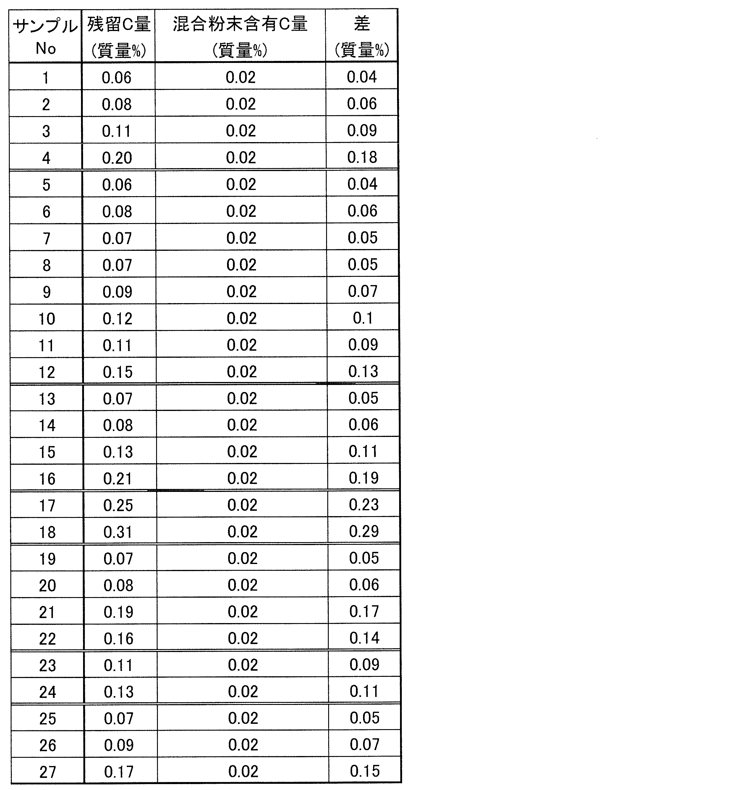
表3において、「残留C量」はX/Zに相当し、「混合粉末含有C量」はY/Zに相当する。表3の「差」は、「残留C量」-「混合粉末含有C量」であり、X/Z-Y/Z=(X-Y)/Zに相当している。
次に、ペーストを塗布する対象であるR-T-B系焼結磁石について説明する。
まず、公知の方法で、組成比Nd=13.4、B=5.8、Al=0.5、Cu=0.1、Co=1.1、残部=Fe(原子%)のR-T-B系焼結磁石を作製した。これを機械加工することにより、5.7mm×15.6mm×70.2mmのR-T-B系焼結磁石母材を得た。得られたR-T-B系焼結磁石母材の磁気特性をB-Hトレーサーによって測定したところ、HcJは1052kA/m、Brは1.45Tであった。なお、R-T-B系焼結磁石母材の不純物量をガス分析装置によって測定したところ、酸素が740ppm、窒素が490ppm、炭素が880ppmであった。
表1に示す種類および配合比で作製したペーストを、上記のR-T-B系焼結磁石母材の15.6mm×70.2mmの大きさの表面にスクリーン印刷法によって塗布した。塗布量は1mm2あたりのTb量が0.07mgとなるように調整した。塗布後、90℃で1時間乾燥した。同様にR-T-B系焼結磁石母材の反対側の面にもペーストを塗布し、乾燥した。
ペーストの塗布膜(乾燥膜)が両面に形成されたR-T-B系焼結磁石を塗布面が垂直面となるように立てて、熱処理を行った。具体的には、常温から10℃/minで400℃まで昇温した後、400℃で2時間の熱処理を行い、更に、10℃/minで900℃まで昇温した後、900℃で8時間の熱処理を施した。
熱処理後の塗膜剥がれの状況を評価した。また、R-T-B系焼結磁石の15.6mm×70.2mmの面を両面から均等に機械加工にて除去して厚さを5.3mmとしてから、図4に示すR-T-B系焼結磁石100の破線で囲まれた部分100aから5.3mm×7.0mm×7.0mmの磁石片を切り出し、B-Hトレーサーによって磁気特性を測定した。剥がれの評価結果(剥がれあり=×、剥がれ無=○)、磁気特性の測定値および総合評価を表4に示す。なお、剥がれが生じたサンプルでは、全て、図4に示す斜線部分を含んだ部分が剥がれていた(裏側の面も同じ)。
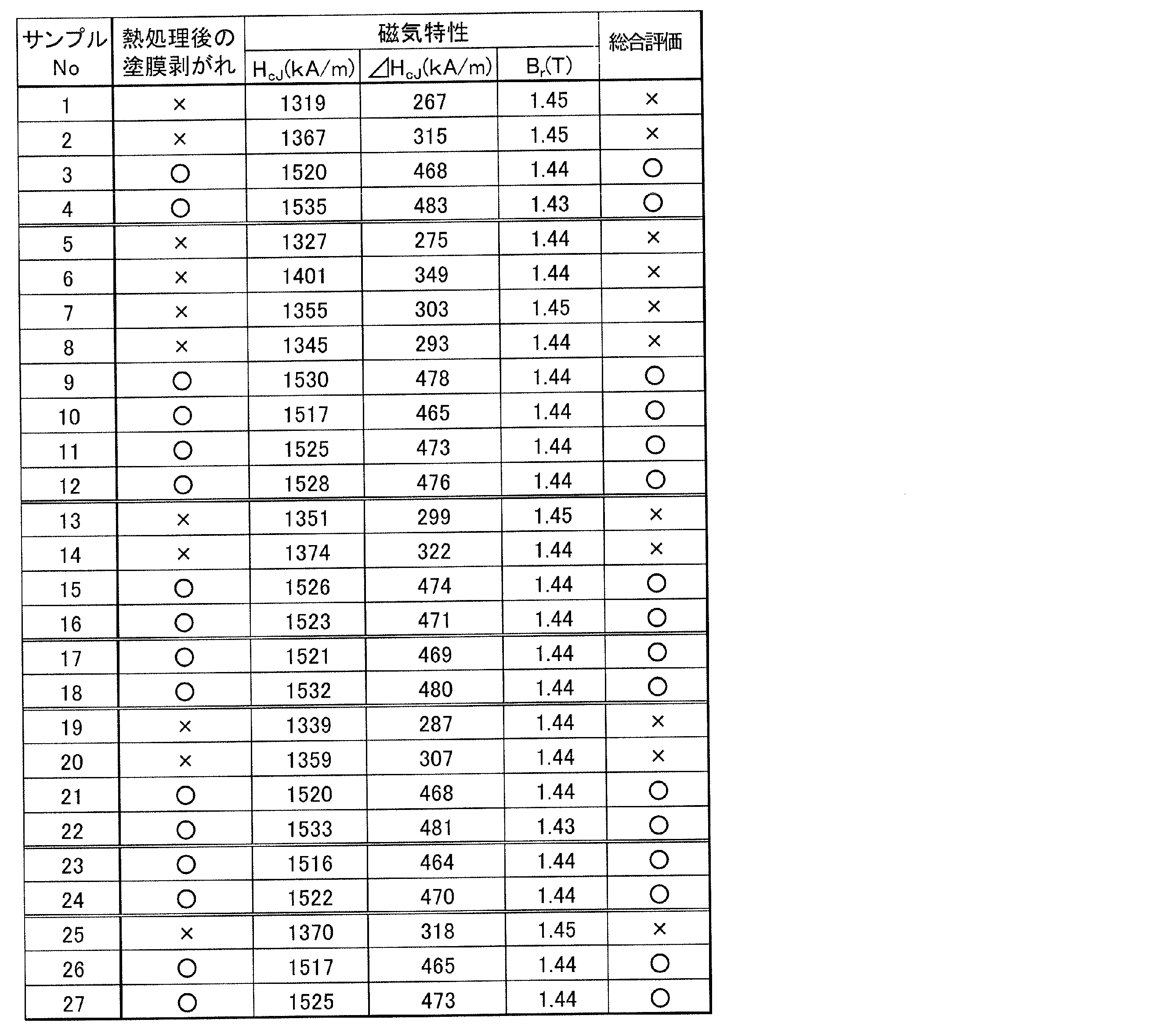
表1~表4からわかるように、表3に示す残留C量の差((X-Y)/Z)が本発明の範囲内であるペーストを塗布して、熱処理を行ったサンプルでは、塗布膜の密着が維持され、HcJも大きく向上していた。しかし、表3の残留C量の差が本発明の範囲外であるペーストを塗布して熱処理したサンプルでは、塗布膜の上部が剥がれて脱落し、HcJの向上度も小さかった。
図5は、表2の混合粉末の割合と表3の「残留C量-混合粉末含有C量」の差を、バインダおよびカップリング剤の種類別に示したグラフである。この図は、「残留C量-混合粉末含有C量」の値が0.07質量%以上の時、熱処理後に塗膜剥がれが無く、0.07質量%を下回るときは塗膜剥がれが生じたことを示している。バインダおよびカップリング剤の種類によらず、混合粉末の割合が多くなるにつれて「残留C量-混合粉末含有C量」は少なくなる傾向にある。ただし、「残留C量-混合粉末含有C量」は、バインダまたはカップリング剤の種類やこれらの配合割合によって異なる。例えば、混合粉末の割合が98.78質量%の場合や98.28質量%の場合を見ると、同じ混合粉末の割合、すなわち同じ量のバインダおよびカップリング剤を用いても、バインダおよびカップリング剤の違いによっては塗膜剥がれが生じることも生じないこともある。さらに、例えば、□で示される、バインダがエチルセルロースでカップリング剤がエポキシ系シランカップリング剤の組み合わせによる値や、●で示される、バインダがPVAでカップリング剤無による値を見ると、同じ樹脂やカップリング剤を用いても、混合粉末の割合の違い(すなわち、用いるバインダおよびカップリング剤の量の違い)やバインダとカップリング剤の配合割合によって「残留C量-混合粉末含有C量」が異なり、塗膜剥がれが生じることも生じないこともある。□と◇(バインダがエチルセルロースでカップリング剤無)からわかるようにカップリング剤の有無も同様で、カップリング剤があってもなくても、塗膜剥がれが生じることも生じないこともある。
図5から、熱処理後の剥がれの有無は、混合粉末の割合、バインダまたはカップリング剤の種類、配合割合の各々によって決まるものではなく、それらの組み合わせによって決まる熱処理後の「残留C量-混合粉末含有C量」に依存していることがわかる。本発明は、このような知見に基づいて完成した。
[実施例2]
下記の表5のサンプルA~Fに示す混合粉末、バインダ、カップリング剤を使用し、実施例1と同様の評価を行った。作製したペーストをPETフィルムに塗布し、90℃で1Hr乾燥した。計算によって求めた乾燥膜中のそれぞれの成分の割合は表6の通りである。
下記の表5のサンプルA~Fに示す混合粉末、バインダ、カップリング剤を使用し、実施例1と同様の評価を行った。作製したペーストをPETフィルムに塗布し、90℃で1Hr乾燥した。計算によって求めた乾燥膜中のそれぞれの成分の割合は表6の通りである。

実施例1について得た表3および表4に対応する表7および表8を以下に示す。
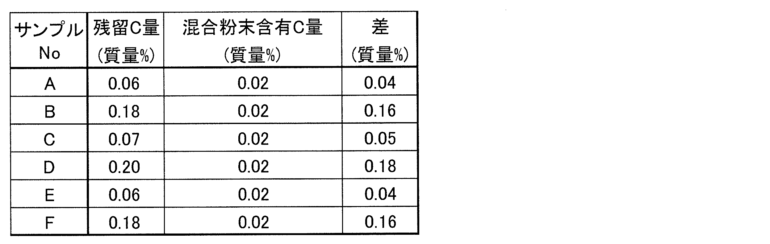

表7および表8からわかるように、実施例1と異なる種類の混合粉末を用いた場合にも、表7の残留C量の差が本発明の範囲内であるペーストを塗布して熱処理したサンプルでは、塗布膜の密着が維持され、HcJも大きく向上していた。しかし、表7の残留C量の差が本発明の範囲外であるペーストを塗布して熱処理したサンプルでは、塗布膜の上部が剥がれて脱落し、HcJの向上度も小さかった。
本発明は、より少ない重希土類元素RHによってR-T-B系焼結磁石のHcJを向上させることができるため、高いHcJが求められる希土類系焼結磁石の製造に使用され得る。また、本発明は、重希土類元素RH以外の他の金属元素を希土類系焼結磁石に表面から拡散させることが必要な技術にも広く適用され得る。
22 金属粉末粒子
24 金属化合物粉末粒子
100 R-T-B系焼結磁石
200 塗布膜
24 金属化合物粉末粒子
100 R-T-B系焼結磁石
200 塗布膜
Claims (5)
- R-T-B系焼結磁石を用意する工程と、
金属粉末および金属化合物粉末が混合された混合粉末と樹脂バインダとを含むペーストの塗布膜を前記R-T-B系焼結磁石の表面に形成する工程と、
前記塗布膜が前記表面に形成された前記R-T-B系焼結磁石に対する熱処理を行うことによって前記塗布膜中の金属成分を前記R-T-B系焼結磁石の内部に拡散させる工程と、
を含み、
前記塗布膜は、前記熱処理工程後にも残存する炭素を含有し、かつ、
前記残存する炭素の含有量から、前記ペーストに含まれていた混合粉末の前記熱処理前における炭素含有量を差し引いた値が、前記熱処理後における前記塗布膜の全体の0.07質量%以上0.50質量%以下の範囲になるように、前記熱処理前における前記塗布膜の炭素含有量が調整されている、希土類系焼結磁石の製造方法。 - 前記熱処理前における乾燥した塗布膜全体に対する前記混合粉末の割合は95質量%以上99質量%以下である、請求項1に記載の希土類系焼結磁石の製造方法。
- 前記混合粉末は、
RLM合金(RLはNdおよび/またはPr、MはCu、Fe、Ga、Co、Niから選ばれる1種以上)の金属粉末と、
RHフッ化物(RHはDyおよび/またはTb)、RH酸フッ化物、およびRH酸化物の少なくとも1つ金属化合物粉末と、
を含有する、請求項1または2に記載の希土類系焼結磁石の製造方法。 - 前記RLM合金の粉末は、前記混合粉末の全体の50質量%以上96質量%以下である、請求項3に記載の希土類系焼結磁石の製造方法。
- 前記ペーストはカップリング剤を含有する、請求項1から4のいずれかに記載の希土類系焼結磁石の製造方法。
Priority Applications (2)
| Application Number | Priority Date | Filing Date | Title |
|---|---|---|---|
| CN201680037646.4A CN107710360B (zh) | 2015-07-29 | 2016-07-15 | 稀土类烧结磁体的制造方法 |
| JP2017530789A JP6604381B2 (ja) | 2015-07-29 | 2016-07-15 | 希土類系焼結磁石の製造方法 |
Applications Claiming Priority (2)
| Application Number | Priority Date | Filing Date | Title |
|---|---|---|---|
| JP2015-149505 | 2015-07-29 | ||
| JP2015149505 | 2015-07-29 |
Publications (1)
| Publication Number | Publication Date |
|---|---|
| WO2017018252A1 true WO2017018252A1 (ja) | 2017-02-02 |
Family
ID=57885483
Family Applications (1)
| Application Number | Title | Priority Date | Filing Date |
|---|---|---|---|
| PCT/JP2016/071015 Ceased WO2017018252A1 (ja) | 2015-07-29 | 2016-07-15 | 希土類系焼結磁石の製造方法 |
Country Status (3)
| Country | Link |
|---|---|
| JP (1) | JP6604381B2 (ja) |
| CN (1) | CN107710360B (ja) |
| WO (1) | WO2017018252A1 (ja) |
Cited By (5)
| Publication number | Priority date | Publication date | Assignee | Title |
|---|---|---|---|---|
| JP2018164004A (ja) * | 2017-03-27 | 2018-10-18 | 日立金属株式会社 | R−t−b系焼結磁石の製造方法 |
| JP2019062155A (ja) * | 2017-09-28 | 2019-04-18 | 日立金属株式会社 | R−t−b系焼結磁石の製造方法 |
| JP2019075493A (ja) * | 2017-10-18 | 2019-05-16 | Tdk株式会社 | 磁石接合体 |
| US20210296049A1 (en) * | 2020-03-17 | 2021-09-23 | Ningbo Jinji Strong Magnetic Material Co., Ltd. | COATING MATERIALS FOR DIFFUSING INTO MAGNET OF NdFeB AND A METHOD OF MAKING IT |
| WO2023073228A1 (en) | 2021-10-29 | 2023-05-04 | CureVac SE | Improved circular rna for expressing therapeutic proteins |
Families Citing this family (1)
| Publication number | Priority date | Publication date | Assignee | Title |
|---|---|---|---|---|
| CN111489874A (zh) * | 2019-01-28 | 2020-08-04 | 日立金属株式会社 | R-t-b系烧结磁体的制造方法 |
Citations (4)
| Publication number | Priority date | Publication date | Assignee | Title |
|---|---|---|---|---|
| JP2009302119A (ja) * | 2008-06-10 | 2009-12-24 | Hitachi Chem Co Ltd | 希土類磁石用処理液及びそれを用いた希土類磁石 |
| JP2010114200A (ja) * | 2008-11-05 | 2010-05-20 | Daido Steel Co Ltd | 希土類磁石の製造方法 |
| JP2011014668A (ja) * | 2009-07-01 | 2011-01-20 | Shin-Etsu Chemical Co Ltd | 希土類磁石の製造方法及び希土類磁石 |
| JP2012234971A (ja) * | 2011-05-02 | 2012-11-29 | Hitachi Metals Ltd | R−t−b系焼結磁石の製造方法 |
Family Cites Families (5)
| Publication number | Priority date | Publication date | Assignee | Title |
|---|---|---|---|---|
| JP2005187929A (ja) * | 2003-12-26 | 2005-07-14 | Tdk Corp | 希土類磁石及びその製造方法 |
| JP4415681B2 (ja) * | 2004-01-21 | 2010-02-17 | Tdk株式会社 | 希土類焼結磁石及びその製造方法 |
| JP5499738B2 (ja) * | 2009-02-03 | 2014-05-21 | 戸田工業株式会社 | 表面処理された希土類系磁性粉末、該希土類系磁性粉末を含有するボンド磁石用樹脂組成物並びにボンド磁石 |
| JP2011258935A (ja) * | 2010-05-14 | 2011-12-22 | Shin Etsu Chem Co Ltd | R−t−b系希土類焼結磁石 |
| JP6597389B2 (ja) * | 2015-03-18 | 2019-10-30 | 日立金属株式会社 | R−t−b系焼結磁石の製造方法 |
-
2016
- 2016-07-15 WO PCT/JP2016/071015 patent/WO2017018252A1/ja not_active Ceased
- 2016-07-15 JP JP2017530789A patent/JP6604381B2/ja active Active
- 2016-07-15 CN CN201680037646.4A patent/CN107710360B/zh active Active
Patent Citations (4)
| Publication number | Priority date | Publication date | Assignee | Title |
|---|---|---|---|---|
| JP2009302119A (ja) * | 2008-06-10 | 2009-12-24 | Hitachi Chem Co Ltd | 希土類磁石用処理液及びそれを用いた希土類磁石 |
| JP2010114200A (ja) * | 2008-11-05 | 2010-05-20 | Daido Steel Co Ltd | 希土類磁石の製造方法 |
| JP2011014668A (ja) * | 2009-07-01 | 2011-01-20 | Shin-Etsu Chemical Co Ltd | 希土類磁石の製造方法及び希土類磁石 |
| JP2012234971A (ja) * | 2011-05-02 | 2012-11-29 | Hitachi Metals Ltd | R−t−b系焼結磁石の製造方法 |
Cited By (8)
| Publication number | Priority date | Publication date | Assignee | Title |
|---|---|---|---|---|
| JP2018164004A (ja) * | 2017-03-27 | 2018-10-18 | 日立金属株式会社 | R−t−b系焼結磁石の製造方法 |
| JP2019062155A (ja) * | 2017-09-28 | 2019-04-18 | 日立金属株式会社 | R−t−b系焼結磁石の製造方法 |
| JP2019075493A (ja) * | 2017-10-18 | 2019-05-16 | Tdk株式会社 | 磁石接合体 |
| JP7020051B2 (ja) | 2017-10-18 | 2022-02-16 | Tdk株式会社 | 磁石接合体 |
| US11335483B2 (en) | 2017-10-18 | 2022-05-17 | Tdk Corporation | Magnet structure |
| US20210296049A1 (en) * | 2020-03-17 | 2021-09-23 | Ningbo Jinji Strong Magnetic Material Co., Ltd. | COATING MATERIALS FOR DIFFUSING INTO MAGNET OF NdFeB AND A METHOD OF MAKING IT |
| US11848152B2 (en) * | 2020-03-17 | 2023-12-19 | Ningbo Jinji Strong Magnetic Material Co., Ltd. | Coating materials for diffusing into magnet of NdFeB and a method of making it |
| WO2023073228A1 (en) | 2021-10-29 | 2023-05-04 | CureVac SE | Improved circular rna for expressing therapeutic proteins |
Also Published As
| Publication number | Publication date |
|---|---|
| JPWO2017018252A1 (ja) | 2018-05-17 |
| CN107710360B (zh) | 2020-01-21 |
| JP6604381B2 (ja) | 2019-11-13 |
| CN107710360A (zh) | 2018-02-16 |
Similar Documents
| Publication | Publication Date | Title |
|---|---|---|
| JP6675855B2 (ja) | 希土類永久磁石及びその製造方法 | |
| JP6604381B2 (ja) | 希土類系焼結磁石の製造方法 | |
| JP5363314B2 (ja) | NdFeB系焼結磁石製造方法 | |
| CN106415752B (zh) | R-t-b系烧结磁铁的制造方法 | |
| JP6414598B2 (ja) | R−t−b系焼結磁石の製造方法 | |
| WO2016039352A1 (ja) | R-t-b系焼結磁石の製造方法 | |
| CN108231392A (zh) | 制备稀土永磁体的方法 | |
| JP5209349B2 (ja) | NdFeB焼結磁石の製造方法 | |
| CN107492429A (zh) | 一种耐高温钕铁硼磁体及其制备方法 | |
| JP6503960B2 (ja) | R−t−b系焼結磁石の製造方法 | |
| JP5643355B2 (ja) | NdFeB焼結磁石の製造方法 | |
| JP6600875B2 (ja) | R−t−b系焼結磁石の製造方法 | |
| JP7424126B2 (ja) | R-t-b系永久磁石 | |
| JP6760169B2 (ja) | R−t−b系焼結磁石の製造方法 | |
| JP2018142640A (ja) | R−t−b系焼結磁石の製造方法 | |
| JP6717231B2 (ja) | R−t−b系焼結磁石の製造方法 | |
| JP2018056156A (ja) | R−t−b系焼結磁石の製造方法 | |
| JP6946904B2 (ja) | 拡散源 | |
| JP7367428B2 (ja) | R-t-b系焼結磁石 | |
| CN110299236B (zh) | R-t-b系烧结磁体的制造方法 | |
| JP2021057565A (ja) | R−t−b系焼結磁石 | |
| JP6414592B2 (ja) | R−t−b系焼結磁石の製造方法 | |
| JP7528437B2 (ja) | R-t-b系焼結磁石の製造方法 | |
| WO2017068946A1 (ja) | R-t-b系焼結磁石の製造方法およびr-t-b系焼結磁石 | |
| JP2019169695A (ja) | R−t−b系焼結磁石の製造方法 |
Legal Events
| Date | Code | Title | Description |
|---|---|---|---|
| 121 | Ep: the epo has been informed by wipo that ep was designated in this application |
Ref document number: 16830357 Country of ref document: EP Kind code of ref document: A1 |
|
| ENP | Entry into the national phase |
Ref document number: 2017530789 Country of ref document: JP Kind code of ref document: A |
|
| NENP | Non-entry into the national phase |
Ref country code: DE |
|
| 122 | Ep: pct application non-entry in european phase |
Ref document number: 16830357 Country of ref document: EP Kind code of ref document: A1 |