WO2017018068A1 - 紙葉類処理装置及び紙葉類鑑別装置 - Google Patents
紙葉類処理装置及び紙葉類鑑別装置 Download PDFInfo
- Publication number
- WO2017018068A1 WO2017018068A1 PCT/JP2016/067109 JP2016067109W WO2017018068A1 WO 2017018068 A1 WO2017018068 A1 WO 2017018068A1 JP 2016067109 W JP2016067109 W JP 2016067109W WO 2017018068 A1 WO2017018068 A1 WO 2017018068A1
- Authority
- WO
- WIPO (PCT)
- Prior art keywords
- unit
- discrimination
- conveyance
- transport
- path
- Prior art date
Links
- 238000012545 processing Methods 0.000 title claims abstract description 29
- 230000032258 transport Effects 0.000 claims description 178
- 230000003287 optical effect Effects 0.000 claims description 62
- 238000003860 storage Methods 0.000 claims description 54
- 230000007246 mechanism Effects 0.000 claims description 31
- 238000009826 distribution Methods 0.000 claims description 19
- 238000001514 detection method Methods 0.000 description 32
- 238000000151 deposition Methods 0.000 description 28
- 230000005540 biological transmission Effects 0.000 description 23
- 238000012546 transfer Methods 0.000 description 20
- 230000002093 peripheral effect Effects 0.000 description 13
- 238000000034 method Methods 0.000 description 12
- 230000008569 process Effects 0.000 description 11
- 238000007789 sealing Methods 0.000 description 11
- 238000012423 maintenance Methods 0.000 description 9
- 239000000428 dust Substances 0.000 description 5
- 230000005856 abnormality Effects 0.000 description 4
- 239000000853 adhesive Substances 0.000 description 4
- 230000001070 adhesive effect Effects 0.000 description 4
- 230000008859 change Effects 0.000 description 4
- 230000006835 compression Effects 0.000 description 3
- 238000007906 compression Methods 0.000 description 3
- 230000000694 effects Effects 0.000 description 3
- 230000004044 response Effects 0.000 description 3
- 230000015556 catabolic process Effects 0.000 description 2
- 238000006731 degradation reaction Methods 0.000 description 2
- 238000006073 displacement reaction Methods 0.000 description 2
- 230000006870 function Effects 0.000 description 2
- 238000007689 inspection Methods 0.000 description 2
- 238000003825 pressing Methods 0.000 description 2
- 238000011144 upstream manufacturing Methods 0.000 description 2
- 238000006243 chemical reaction Methods 0.000 description 1
- 238000012937 correction Methods 0.000 description 1
- 239000004973 liquid crystal related substance Substances 0.000 description 1
- 230000005389 magnetism Effects 0.000 description 1
- 238000004519 manufacturing process Methods 0.000 description 1
- 239000002184 metal Substances 0.000 description 1
- 230000008439 repair process Effects 0.000 description 1
- 230000008054 signal transmission Effects 0.000 description 1
- 238000004804 winding Methods 0.000 description 1
Images


Classifications
-
- G—PHYSICS
- G07—CHECKING-DEVICES
- G07D—HANDLING OF COINS OR VALUABLE PAPERS, e.g. TESTING, SORTING BY DENOMINATIONS, COUNTING, DISPENSING, CHANGING OR DEPOSITING
- G07D7/00—Testing specially adapted to determine the identity or genuineness of valuable papers or for segregating those which are unacceptable, e.g. banknotes that are alien to a currency
- G07D7/04—Testing magnetic properties of the materials thereof, e.g. by detection of magnetic imprint
-
- B—PERFORMING OPERATIONS; TRANSPORTING
- B65—CONVEYING; PACKING; STORING; HANDLING THIN OR FILAMENTARY MATERIAL
- B65H—HANDLING THIN OR FILAMENTARY MATERIAL, e.g. SHEETS, WEBS, CABLES
- B65H5/00—Feeding articles separated from piles; Feeding articles to machines
- B65H5/36—Article guides or smoothers, e.g. movable in operation
- B65H5/38—Article guides or smoothers, e.g. movable in operation immovable in operation
-
- B—PERFORMING OPERATIONS; TRANSPORTING
- B65—CONVEYING; PACKING; STORING; HANDLING THIN OR FILAMENTARY MATERIAL
- B65H—HANDLING THIN OR FILAMENTARY MATERIAL, e.g. SHEETS, WEBS, CABLES
- B65H29/00—Delivering or advancing articles from machines; Advancing articles to or into piles
- B65H29/52—Stationary guides or smoothers
-
- B—PERFORMING OPERATIONS; TRANSPORTING
- B65—CONVEYING; PACKING; STORING; HANDLING THIN OR FILAMENTARY MATERIAL
- B65H—HANDLING THIN OR FILAMENTARY MATERIAL, e.g. SHEETS, WEBS, CABLES
- B65H29/00—Delivering or advancing articles from machines; Advancing articles to or into piles
- B65H29/58—Article switches or diverters
- B65H29/60—Article switches or diverters diverting the stream into alternative paths
-
- G—PHYSICS
- G07—CHECKING-DEVICES
- G07D—HANDLING OF COINS OR VALUABLE PAPERS, e.g. TESTING, SORTING BY DENOMINATIONS, COUNTING, DISPENSING, CHANGING OR DEPOSITING
- G07D7/00—Testing specially adapted to determine the identity or genuineness of valuable papers or for segregating those which are unacceptable, e.g. banknotes that are alien to a currency
- G07D7/06—Testing specially adapted to determine the identity or genuineness of valuable papers or for segregating those which are unacceptable, e.g. banknotes that are alien to a currency using wave or particle radiation
- G07D7/12—Visible light, infrared or ultraviolet radiation
-
- G—PHYSICS
- G07—CHECKING-DEVICES
- G07D—HANDLING OF COINS OR VALUABLE PAPERS, e.g. TESTING, SORTING BY DENOMINATIONS, COUNTING, DISPENSING, CHANGING OR DEPOSITING
- G07D9/00—Counting coins; Handling of coins not provided for in the other groups of this subclass
Definitions
- the present disclosure relates to a paper sheet processing apparatus and a paper sheet discrimination apparatus, and is applicable to, for example, an automatic cash transaction apparatus (ATM) that performs a desired transaction by inserting a medium such as banknotes. And a paper sheet discrimination device.
- ATM automatic cash transaction apparatus
- an automatic cash transaction apparatus or the like used in a financial institution or a store causes a customer to deposit cash such as banknotes and coins according to the transaction contents with the customer, and also withdraws cash to the customer.
- an automatic teller machine for example, a deposit / withdrawal unit that exchanges bills with customers, a discrimination unit that discriminates the denomination and authenticity of inserted bills, and temporarily holds the inserted bills.
- Some have a temporary storage unit, a transport unit that transports banknotes, and a banknote storage that stores banknotes for each denomination (see, for example, JP-A-2013-205940).
- the present disclosure provides a paper sheet processing apparatus and a paper sheet discrimination apparatus that can be miniaturized.
- 1st aspect of this indication is a paper sheet processing apparatus, Comprising: While forming the discrimination part conveyance path where paper sheets are conveyed, the reading means which reads the characteristic of paper sheets to this discrimination part conveyance path The provided discrimination part and the discrimination part are detachable, and by attaching the discrimination part, the paper sheet is conveyed in a different direction from the discrimination part conveyance path connected to the discrimination part between the discrimination part A transport unit that forms a transport path.
- a second aspect of the present disclosure is a paper sheet discrimination device, which is detachable from a predetermined transport unit, forms a discrimination part transport path through which the paper sheet is transported, and transports the discrimination part By providing reading means to read the characteristics of paper sheets on the path and being attached to the transport unit, the paper sheet is transported in a different direction from the discrimination unit transport path connected to the transport unit.
- a transporting section transporting path.
- the length of the discrimination section transport path can be shortened by not providing a delivery section between the discrimination section transport path and the transport section transport path.
- the above aspect of the present disclosure can provide a paper sheet processing apparatus and a paper sheet discrimination apparatus that can be miniaturized.
- the automatic teller machine 1 is configured around a box-shaped housing 2, and is installed in a financial institution, for example, for a deposit transaction or a withdrawal transaction with a customer. Transactions related to cash.
- the housing 2 is provided with a customer-facing unit 3 at a location where it is easy to insert bills or operate with a touch panel while the customer faces the front side.
- the customer service section 3 is provided with a card entry / exit port 4, a deposit / withdrawal port 5, an operation display unit 6, a numeric keypad 7 and a receipt issuance port 8.
- Information notification and operation instructions are received.
- the card entry / exit 4 is a portion into which various cards such as a cash card are inserted or ejected.
- a card processing unit (not shown) for reading account numbers and the like magnetically recorded on various cards is provided on the back side of the card slot 4.
- the deposit / withdrawal port 5 is a portion where a bill to be deposited by a customer is inserted and a bill to be dispensed to the customer is discharged.
- the operation display unit 6 is integrated with an LCD (Liquid Crystal Display) for displaying an operation screen at the time of transaction and a touch panel for selecting a transaction type, inputting a personal identification number, a transaction amount, and the like.
- the numeric keypad 7 is a physical key that accepts input of numbers such as “0” to “9”, and is used when a password or transaction amount is input.
- the receipt issuing port 8 is a part that issues a receipt on which transaction details are printed at the end of transaction processing.
- the main control section 9 for controlling and controlling the entire automatic teller machine 1, a banknote depositing / dispensing machine 10 for performing various processes related to banknotes, and the like.
- the main control unit 9 is composed mainly of a CPU (Central Processing Unit) (not shown) and includes a storage unit including a ROM (Read Only Memory), a RAM (Random Access Memory), a hard disk drive, a flash memory, and the like. By reading and executing a predetermined program, each unit is controlled to perform various processes such as a deposit transaction and a withdrawal transaction.
- the side facing the user of the automatic teller machine 1 is the front side, the opposite is the rear side, the left and right are the left side and the right side as viewed from the user facing the front side, respectively, and the upper side and The lower side is defined and described.
- the banknote depositing / dispensing machine 10 is configured around a box-shaped depositing / dispensing machine housing 11, and the control unit 12 includes each unit (the depositing / dispensing unit 16, the discrimination unit 18, the temporary storage unit 20 , The fake ticket storage 22, the transport unit 24, the bill storage 26 and the reject storage 28) are controlled.
- the control unit 12 is mainly configured by a CPU (not shown), and controls each unit by reading and executing a predetermined program from the storage unit 14 including a ROM, a RAM, a hard disk drive, a flash memory, and the like.
- Various processing such as deposit transactions and withdrawal transactions.
- a depositing / dispensing part 16 On the upper side of the inside of the banknote depositing / dispensing machine 10, a depositing / dispensing part 16, a discrimination part 18 for judging the denomination and authenticity of the banknote, a temporary holding part 20 for temporarily retaining the deposited banknote and the counterfeit banknote (hereinafter, There is provided a fake ticket storage 22 or the like for storing bills determined to be called fake bills).
- the deposit / withdrawal unit 16 is arranged on the upper front side in the deposit / withdrawal machine casing 11, separates the banknotes thrown from the customer one by one and feeds them to the transport unit 24.
- the transport unit 24 transports rectangular banknotes in the short direction along a transport path indicated by a solid line in the drawing by a roller, a belt, or the like (not shown).
- the conveyance part 24 conveys a banknote so that the discrimination part 18 may be penetrated in the front-back direction, and has connected the back side of this discrimination part 18, the temporary storage part 20, the banknote storage 26, and the fake ticket storage 22. .
- the conveyance part 24 has connected the front side of the discrimination part 18, the depositing / withdrawing part 16, and the rejection store
- FIG. A selector (indicated by a triangle in the figure) is provided at a branch point of the transport unit 24, and the transport destination of the bills is switched by rotating based on the control of the control unit 12.
- the discriminating unit 18 discriminates the denomination and authenticity of the banknotes, the degree of damage (loss), etc. (correction) using an optical element, a magnetic detection element, etc. Notify the control unit 12. Moreover, the discrimination part 18 reads and identifies a serial number from the image data of the imaged banknote, and notifies the control part 12 of the identification result. In response to this, the control unit 12 determines the banknote transport destination based on the acquired discrimination result and identification result. This discrimination part 18 is comprised by the discrimination connection conveyance part 30 and the discrimination sensor part 40 which are mentioned later.
- the temporary storage unit 20 is arranged at a position adjacent to the transport unit 24 in the substantially central portion in the front-rear direction in the deposit / withdrawal machine housing 11.
- the temporary storage unit 20 employs a so-called tape escrow method, stores the banknotes by winding the banknotes together with the tape around the peripheral side surface of the cylindrical drum, and also peels the tapes from the peripheral side surface. To pay out.
- the fake ticket warehouse 22 is arranged at a position adjacent to the upper part of the rear side in the depositing / dispensing machine housing 11 and above the transport unit 24, and has a space for storing banknotes therein.
- the counterfeit bill warehouse 22 stores the bill.
- a reject box 28 for storing banknotes that should not be reused and five banknote storage boxes 26 for storing reusable banknotes are provided below the inside of the banknote depositing and dispensing machine 10.
- the reject box 28 is arranged in the lower part on the front side in the depositing / dispensing machine casing 11 and is formed in a rectangular parallelepiped shape that is long in the vertical direction and has a space for accumulating and storing banknotes therein.
- the reject box 28 stores the banknote therein.
- Each banknote storage 26 is configured in the same manner, and is formed in a rectangular parallelepiped shape that is long in the vertical direction, and has a space for accumulating and storing banknotes therein.
- denominations of banknotes to be stored are set in advance.
- the banknote storage 26 is transported by the transport unit 24 according to the denomination of the banknote determined to be reusable with a small degree of damage by the discrimination unit 18 and the control unit 12, Banknotes are collected and stored inside.
- the banknote storage 26 receives the instruction
- the automatic teller machine 1 is configured such that the main control unit 9 and the control unit 12 control each unit based on the banknote discrimination result and the identification result by the discrimination unit 18, and the banknote depositing process and the withdrawal process. I do.
- the automatic teller machine 1 when a deposit transaction is selected by the customer via the operation display unit 6 and a bill is inserted into the deposit / withdrawal unit 16 at the time of deposit transaction, one bill is inserted from the deposit / withdrawal unit 16. Each of them is conveyed to the discrimination unit 18 and conveyed in the discrimination unit 18.
- the automatic teller machine 1 transports the depositable banknotes determined to be depositable based on the discrimination result and the identification result of the discrimination unit 18 to the temporary storage unit 20 and temporarily stores them.
- the automatic teller machine 1 returns the deposit reject banknote determined to be unsuitable for depositing to the depositing / dispensing unit 16 and returning it to the customer.
- the automatic teller machine 1 determines each banknote storage according to the denomination of banknotes determined to be storable among banknotes stored in the temporary storage unit 20. Transport to 26 and store. On the other hand, the automatic teller machine 1 conveys banknotes determined to be counterfeit to the counterfeit bank 22. Moreover, the automatic teller machine 1 conveys the banknote determined to be unsuitable for storage to the rejection store
- the automatic teller machine 1 pays out banknotes from each banknote storage 26 according to the number of banknotes for each denomination, conveys them to the discrimination unit 18, and conveys the inside of the discrimination unit 18. Get.
- the automatic teller machine 1 conveys to the depositing / withdrawing unit 16 the banknotes that can be withdrawn which are determined to be withdrawable based on the discrimination result and the identification result of the discrimination unit 18.
- the automatic teller machine 1 conveys and stores the withdrawal reject banknote determined to be unsuitable for withdrawal to the rejection store 28. And when the banknote for request
- FIG. 3 shows the discrimination unit 18 in a normal state where the automatic teller machine 1 is operated as usual.
- the identification connection conveyance unit 30 includes a box-shaped lower conveyance frame 39A extending in the front-rear direction and a box-shaped pre-conveyance frame 39B arranged in front of the conveyance lower frame 39A and extending in the vertical direction.
- the discrimination sensor unit 40 includes a box-type discrimination upper frame 49A extending in the front-rear direction, and a box-type discrimination lower frame 49B arranged below the discrimination upper frame 49A and extending in the front-rear direction.
- the lower transport frame 39A and the pre-transport frame 39B are collectively referred to as a transport unit frame 39
- the upper discrimination frame 49A as the discrimination first frame and the lower discrimination frame 49B as the second discrimination frame are collectively identified.
- the lower transport frame 39A, the pre-transport frame 39B, the lower discrimination frame 49B, and the upper discrimination frame 49A are frame members that support the components in the discrimination unit 18. Between the lower discrimination frame 49B and the upper discrimination frame 49A, between the lower discrimination frame 49B and the pre-transportation frame 39B, between the lower transport frame 39A and the pre-transportation frame 39B, and between the upper discrimination frame 49A and the pre-transportation frame 39B Between the two, a conveyance path 43 for conveying the banknote BL is provided.
- the identification upper frame 49A is configured to be rotatable so that the rear end moves upward with the rotation fulcrum 37 provided at the front end portion as an axis.
- the discrimination upper frame 49A is rotated about the rotation fulcrum 37 by the maintenance operator, thereby changing from the normal state shown in FIG. It becomes an open state shown in FIG.
- the discrimination sensor conveyance path 43A (described later) is opened to the outside and is easily accessible to the maintenance worker.
- the lower conveyance frame 39A is formed with an identification sensor portion attachment location 35A and an identification sensor portion attachment location 35B that protrude upward from the upper plate-like portion extending in the front-rear direction toward the lower plate-like portion of the identification lower frame 49B. ing.
- the discrimination lower frame 49B is transported by screwing a discrimination sensor unit fixing member 46A such as a screw into the discrimination sensor unit mounting location 35A and a discrimination sensor unit fixing member 46B such as a screw into the discrimination sensor unit mounting location 35B.
- the frame 39A is detachably fixed.
- the conveyance path 43 includes a discrimination sensor conveyance path 43A, a branching section 43B, a deposit / withdrawal section side conveyance path 43C, and a reject storage side conveyance path 43D.
- the discrimination sensor conveyance path 43A extends from the conveyance path transfer section 80A to the branch section 43B between the discrimination upper frame 49A and the discrimination lower frame 49B.
- the conveyance path delivery unit 80A is a part that delivers bills to the rear of the identification unit 18 of the conveyance unit 24 (FIG. 2) at the rear end of the identification sensor unit 40.
- the discrimination sensor transport path 43A causes the bill BL to travel in the front-rear direction between the transport path transfer section 80A and the branch section 43B.
- the branching portion 43B is located between the upper discrimination frame 49A, the lower discrimination frame 49B, and the pre-conveyance frame 39B. It is arranged between.
- the branching portion 43B branches from the front end of the discrimination sensor conveyance path 43A to above and below the discrimination sensor portion 40.
- the deposit / withdrawal unit side conveyance path 43C as the conveyance unit first conveyance path extends from the branch portion 43B to the deposit / withdrawal unit side delivery unit 80B between the discrimination upper frame 49A and the pre-conveyance frame 39B.
- the deposit / withdrawal unit-side delivery unit 80 ⁇ / b> B functions as a first delivery unit that is a location for delivering the deposit / withdrawal unit 16 and banknotes at the upper end of the discrimination sensor unit 40.
- the deposit / withdrawal unit side conveyance path 43C moves the bill BL in the vertical direction between the branching unit 43B and the deposit / withdrawal unit side delivery unit 80B.
- the reject box side transfer path 43D as the transfer section second transfer path extends from the branch section 43B to the reject box delivery section 80C between the lower discrimination frame 49B and the lower transfer frame 39A and the pre-transfer frame 39B.
- the reject store delivery unit 80 ⁇ / b> C is a location that delivers the reject store 28 and banknotes at the lower end of the discrimination sensor unit 40.
- Reject warehouse side conveyance path 43D makes bill BL run in the up-and-down direction between this branching part 43B and this rejection warehouse delivery part 80C.
- the deposit / withdrawal unit side conveyance path 43C and the reject storage side conveyance path 43D are collectively referred to as a conveyance unit conveyance path 43CD.
- the banknote deposit / withdrawal machine 10 transfers the banknote BL along the transport path 43 from the deposit / withdrawal unit side transfer unit 80B to the transport path transfer unit 80A or from the transport path transfer unit 80A. While making it run to the side delivery part 80B or the conveyance path delivery part 80A to the rejection store delivery part 80C, the discrimination process of the banknote BL is performed.
- the discrimination unit 18 includes a conveyance lower conveyance guide 31, a conveyance front conveyance guide 32, an identification upper conveyance guide 41, a identification lower conveyance guide 42, and driving rollers 33A, 33B, 33C, 44A, and 44B around the conveyance path 43. And 44C, driven rollers 34A, 45D, 45E, 45A, 45B and 45C, a distribution mechanism 36, a thickness information acquisition unit 50, an optical information acquisition unit 60, and a magnetic information acquisition unit 70. Yes.
- the lower conveyance guide 31 is a guide member that is provided at the front end of the lower conveyance frame 39A and guides banknotes.
- the pre-conveyance conveyance guide 32 is a guide member that is provided at the rear end of the pre-conveyance frame 39B and that opposes the conveyance lower conveyance guide 31, the identification upper conveyance guide 41, and the identification lower conveyance guide 42 to guide bills.
- the identification upper conveyance guide 41 as the identification unit first conveyance guide has a shape that extends along the front-rear direction and the front end is curved upward.
- the discrimination upper conveyance guide 41 is a guide member that is provided at the front end and the lower end of the discrimination upper frame 49A and faces the discrimination lower conveyance guide 42 and the conveyance front conveyance guide 32 to guide a bill.
- the lower discrimination conveyance guide 42 as the discrimination unit second conveyance guide has a shape that extends along the front-rear direction and the front end is curved downward.
- the lower discrimination conveyance guide 42 is a guide member that is provided at the front end and upper end of the lower discrimination frame 49B and faces the discrimination upper conveyance guide 41 and the pre-conveyance conveyance guide 32 to guide bills.
- the lower conveyance guide 31 and the previous conveyance guide 32 are collectively referred to as a conveyance unit conveyance guide
- the upper discrimination conveyance guide 41 and the lower identification conveyance guide 42 are also collectively referred to as a discrimination unit conveyance guide.
- the thickness information acquisition unit 50 acquires the thickness information of the banknote BL
- the optical information acquisition unit 60 acquires the image information of the banknote BL
- the magnetic information acquisition unit 70 acquires the magnetic information of the banknote BL.
- the thickness information acquisition unit 50, the optical information acquisition unit 60, and the magnetic information acquisition unit 70 are collectively referred to as a reading unit 76.
- the drive rollers 33A, 33B and 33C are attached to the front conveyance guide 32 so as to be rotatable at predetermined intervals in the left-right direction so that the drive rollers 33A, 33B, and 33C are oriented in the left-right direction, that is, in the direction orthogonal to the conveyance direction of the bills BL It has been.
- the drive rollers 33A, 33B, and 33C project part of their outer peripheral surfaces into the conveyance path 43 from openings formed in the conveyance front conveyance guide surface 32S.
- Drive rollers 44A, 44B, and 44C and a thickness reference roller 51 are mounted on the upper side of the discrimination lower conveyance guide 42 so as to be rotatable at predetermined intervals in the left-right direction around the left-right direction.
- the magnetic gap roller 73 is also attached at a predetermined interval in the left-right direction so as to be rotatable about the left-right direction and movable in the up-down direction.
- a follower roller 45D is attached to the front side of the lower discrimination conveyance guide 42 at a predetermined interval in the left-right direction so as to be rotatable about the left-right direction and movable in the front-rear direction.
- the magnetic gap roller 73, the drive rollers 44A, 44B and 44C, the thickness reference roller 51, and the driven roller 45D have a part of their outer peripheral surfaces that are moved from the opening formed in the differential lower conveyance guide surface 42S to the conveyance path 43. It is protruding.
- driven rollers 45A, 45B, and 45C are attached at predetermined intervals in the left-right direction so as to be rotatable about the left-right direction and movable in the vertical direction.
- a follower roller 45E is attached to the front side of the discrimination upper conveyance guide 41 at a predetermined interval in the left-right direction so as to be rotatable about the left-right direction and movable in the front-rear direction.
- the driven rollers 45 ⁇ / b> A, 45 ⁇ / b> B, 45 ⁇ / b> C, and 45 ⁇ / b> E project a part of their outer peripheral surfaces into the conveyance path 43 from openings formed in the discrimination upper conveyance guide surface 41 ⁇ / b> S.
- a driven roller 34A is attached to the lower conveyance guide 31 at a predetermined interval in the left-right direction so as to be rotatable about the left-right direction and movable in the front-rear direction.
- the driven roller 34A has a part of the outer peripheral surface projecting into the transport path 43 from an opening formed in the transport lower transport guide surface 31S.
- the driven rollers 34A, 45D, 45E, 45A, 45B and 45C are pressed against the driving rollers 33A, 33B, 33C, 44A, 44B and 44C by urging members (not shown) which are compression springs, respectively.
- the thickness information acquisition unit 50 includes a thickness detection roller unit 52, a gap sensor 55, and a thickness reference roller 51.
- the thickness detection roller portion 52 is attached to the discrimination upper frame 49A so as to be rotatable about the left-right direction at the fulcrum portion 52A.
- the roller portion of the thickness detection roller unit 52 has a part of the outer peripheral surface protruding into the conveyance path 43 from an opening formed in the discrimination upper conveyance guide surface 41S.
- the roller portion of the thickness detection roller portion 52 is attached to the thickness detection roller bracket so as to be rotatable about the left-right direction at the rotation fulcrum portion 52B.
- the thickness detection roller unit 52 is pressed against the thickness reference roller 51 by an urging member (not shown) that is a compression spring.
- the gap sensor 55 is provided above the thickness detection roller unit 52.
- the gap sensor 55 detects the relative displacement amount of the thickness detection roller unit 52 with reference to the position when the thickness detection roller unit 52 contacts the thickness reference roller 51, and the detection result is the thickness. Information is sent to the control unit 12.
- the control unit 12 compares the detection result with the reference value of the thickness stored in advance to determine whether the displacement amount corresponds to one bill or a plurality of bills. The presence or absence of pasting of etc. is judged.
- the optical information acquisition unit 60 includes a reflection / transmission sensor unit 61U located on the upper side and a reflection sensor unit 61D located on the lower side.
- the reflection / transmission sensor unit 61U and the reflection sensor unit 61D have the same configuration of the reflection sensor unit, and are arranged to face each other up and down across the identification sensor transport path 43A.
- the reflection / transmission sensor unit 61U will be mainly described, and the description of the reflection sensor unit 61D will be omitted.
- the member with “D” at the end of the reference numeral in the reflection sensor unit 61D is the member with the same reference numeral as the reflection sensor unit 61D and the letter “U” at the end in the reflection / transmission sensor unit 61U. It corresponds.
- the reflection / transmission sensor unit 61U has an optical sensor case 62U.
- the optical sensor case 62U has a box shape with the lower part opened, and the lower ends of the front side and the rear side are bonded and fixed to the discrimination upper conveyance guide 41.
- the optical information acquisition unit 60 detects the reflection pattern and the transmission pattern of the banknote BL, and sends the detection result to the control unit 12 as image information. In response to this, the control unit 12 determines the authenticity and denomination of the banknote BL, the degree of damage (loss), and the like using the reflection pattern and transmission pattern of the banknote BL acquired from the optical information acquisition section 60. .
- the magnetic sensor 71 is fixed to the upper discrimination conveyance guide 41 on the upper side of the discrimination sensor conveyance path 43A.
- the magnetic gap roller 73 is pressed against a limiter member (not shown) by an urging member (not shown) which is a compression spring so as to leave a gap between the outer peripheral surface of the magnetic gap roller 73 and the detection surface of the magnetic sensor 71.
- the magnetic information acquisition part 70 detects the magnetism of the banknote BL conveyed by the discrimination sensor conveyance path 43A with the magnetic sensor 71, and sends the detection result to the control part 12 as magnetic information.
- the control unit 12 determines the authenticity or denomination of the banknote using the magnetic detection result of the banknote BL acquired from the magnetic information acquisition unit 70.
- the driving rollers 33A, 33B, 33C, 44A, 44B and 44C, the thickness reference roller 51, and the magnetic gap roller 73 are rotated by a driving force transmitted from an actuator (not shown).
- the driven rollers 34A, 45D, 45E, 45A, 45B, and 45C and the thickness detection roller unit 52 are rotated by the rotation of the rollers while pressing the bill BL against the opposing rollers.
- the discrimination part 18 conveys the banknote BL along the conveyance path 43.
- the distribution mechanism 36 is a blade whose front end is directed rearward, and has an upper distribution surface 36A on the upper end surface and a lower distribution surface 36B on the lower end surface, and is rotatable left and right about the rotation shaft 36C. A plurality are attached to the pre-transport frame 39B in the direction.
- the sorting mechanism 36 is configured to change the direction of blade inclination by rotating by an actuator (not shown) to switch the banknote transport path in two ways.
- the distribution mechanism 36 changes the inclination direction of the blades to form a conveyance path connecting the discrimination sensor conveyance path 43A and the deposit / withdrawal part side conveyance path 43C, or the discrimination sensor conveyance path 43A and the reject warehouse side conveyance path 43D. A conveyance path connecting the two is formed.
- the sorting mechanism 36 uses the upper sorting surface 36A at the branching portion 43B to transfer the bill BL conveyed from the upper part to the lower part in the deposit / withdrawal unit side conveyance path 43C to the identification sensor conveyance path 43A or the identification.
- the bills BL transported from the rear to the front in the sensor transport path 43A are distributed to the deposit / withdrawal part transport path 43C.
- the sorting mechanism 36 sorts the banknotes BL transported from the rear to the front in the discrimination sensor transport path 43A to the reject storage side transport path 43D by the lower sorting surface 36B.
- the discrimination unit 18 drives the sorting mechanism 36 with an actuator (not shown) and switches the tip to face downward based on the control of the control unit 12, so that the depositing / dispensing unit side conveyance path
- the bill BL is allowed to pass from 43C to the discrimination sensor conveyance path 43A.
- the discrimination unit 18 transmits driving force to the driving rollers 33C, 44C, 44B and 44A, the thickness reference roller 51, and the magnetic gap roller 73 by an actuator (not shown).
- the discrimination unit 18 When the bill BL is conveyed from the deposit / withdrawal unit 16 to the discrimination unit 18 via the deposit / withdrawal unit side delivery unit 80B, the discrimination unit 18 first sandwiches the bill between the driving roller 33C and the driven roller 45E and is driven by the driven roller 45E. The bill BL is pressed against the roller 33C to transmit a downward driving force, and the bill BL is moved downward and conveyed to the sorting mechanism 36. The bills BL are transported to the discrimination sensor transport path 43 ⁇ / b> A by changing their direction in the backward direction by hitting the upper sorting surface 36 ⁇ / b> A of the sorting mechanism 36.
- the discrimination unit 18 conveys the bill BL in the discrimination sensor conveyance path 43A by the driving force of the driving roller 33C and the driven roller 45E, and pushes up the driven roller 45C by the bill BL.
- the discriminating unit 18 sandwiches the banknote between the driving roller 44C and the driven roller 45C, presses the banknote BL against the driving roller 44C by the driven roller 45C, and transmits the driving force in the backward direction. Transport to the acquisition unit 70.
- the bill BL is conveyed without clogging a gap provided between the detection surface of the magnetic sensor 71 and the magnetic gap roller 73 by the driving force of the magnetic gap roller 73 of the magnetic information acquisition unit 70. While the bill BL passes through the magnetic information acquisition unit 70, the discrimination unit 18 acquires magnetic information such as magnetic ink on the surface of the bill BL by the magnetic information acquisition unit 70.
- the discrimination unit 18 conveys the bill BL backward by the driving force of the driving roller 44C and the driven roller 45C, and pushes up the driven roller 45B by the bill BL.
- the discrimination unit 18 sandwiches the banknote between the driving roller 44B and the driven roller 45B, presses the banknote BL against the driving roller 44B by the driven roller 45B, and transmits the driving force in the backward direction. It is conveyed to the acquisition unit 60.
- the discrimination unit 18 acquires image information such as a reflected image and a transmission image on the surface of the bill BL by the optical information acquisition unit 60. To do.
- the discrimination unit 18 conveys the bill BL backward by the driving force of the driving roller 44B and the driven roller 45B, and pushes up the driven roller 45A by the bill BL.
- the discrimination unit 18 sandwiches the banknote between the driving roller 44A and the driven roller 45A, presses the banknote BL against the driving roller 44A by the driven roller 45A, and transmits the driving force in the backward direction. It is conveyed to the information acquisition unit 50.
- the discrimination unit 18 conveys the bill BL backward by the driving force of the driving roller 44A and the driven roller 45A, and pushes up the thickness detection roller unit 52 by the bill BL.
- the discrimination unit 18 sandwiches the banknote between the thickness detection roller unit 52 and the thickness reference roller 51, and presses the banknote BL against the thickness reference roller 51 by the thickness detection roller unit 52, thereby driving the driving force in the backward direction. To communicate. While the bill BL passes through the thickness information acquisition unit 50, the discrimination unit 18 detects a change in the movement of the thickness detection roller unit 52 by the gap sensor 55, and acquires the thickness information of the bill BL.
- the discrimination unit 18 transports the bill BL backward by the driving force of the thickness detection roller unit 52 and the thickness reference roller 51, and feeds it out to the rear of the discrimination unit 18 via the transport path delivery unit 80A.
- the control unit 12 acquires information on the banknote BL acquired by the magnetic information acquisition unit 70, the optical information acquisition unit 60, and the thickness information acquisition unit 50 by a signal transmission unit (not shown), and authenticates the money of the banknote BL. Differentiate species, degree of fouling, etc.
- the control unit 12 conveys and stores the banknote BL to the temporary storage unit 20 or conveys and returns the bill BL to the deposit / withdrawal unit 16.
- the above describes the operation when the bill BL is transported during the deposit process.
- the banknote BL is conveyed from the temporary storage unit 20 to the banknote storage 26 or the rejection store 28 during the storage process, and when the banknote BL is transferred from the banknote storage 26 to the deposit / withdrawal unit 16 or the rejection store 28 during the withdrawal process.
- the discriminating unit 18 reverses the rotation direction of each roller with respect to the depositing process and appropriately switches the sorting mechanism 36.
- FIG. 15 As a conventional banknote depositing and dispensing machine, as shown in FIG. 15 in which members corresponding to those in FIG. 3 are assigned the same reference numerals, a discrimination unit 218 and a transport unit 224 are used instead of the discrimination unit 18 (FIG. 3).
- the conveyance unit 224 has a rectangular parallelepiped shape and is configured to be detachable from the frame 211.
- the discrimination unit 218 has a rectangular parallelepiped shape, and is arranged behind the transport unit 224 so as to be detachable from the frame 211. Between the discrimination part 218 and the conveyance part 224, the delivery part 280G which delivers a banknote between this discrimination part 218 and this conveyance part 224 is formed.
- the banknote BL passes through the delivery unit 280G between the discrimination unit 218 and the transport unit 224.
- the vertical width of the conveyance path 243 of the discrimination unit 218 be narrow enough to prevent the banknote BL from jamming (paper jam).
- the vertical positions of the transport unit 224 and the discrimination unit 218 may not match due to manufacturing variation of parts, etc., if the vertical width of the transport path 243 is narrowed, the bill BL is jammed in the delivery unit 280G. There is a possibility.
- the delivery part 280G exists in the discrimination part 218 and the conveyance part 224, the distance between the drive rollers 33B and 33C and the drive roller 44C will become long.
- the discrimination unit 218 and the transport unit 224 have a complicated configuration in which the number of components cannot be reduced because the driving roller 234B and the driven roller 245B need to be disposed on the front side of the delivery unit 280G, and the front-rear direction The length of was long.
- a discrimination unit 318 is provided instead of the discrimination unit 218 (FIG. 15). .
- the discrimination unit 318 is omitted the drive roller 44C and the driven roller 45C. Since the driving roller 44C and the driven roller 45C are omitted from the discrimination unit 218, the discrimination unit 318 has a length in the front-rear direction corresponding to the space occupied by the drive roller 44C and the driven roller 45C than the discrimination unit 218. Can also be shortened.
- the driving roller 234B and the driven roller 245B that are arranged in the nearest vicinity of the upstream side of the magnetic information acquisition part 70 at the time of deposit processing are provided in the conveyance part 224 instead of the discrimination part 318. It becomes.
- the magnetic information acquisition unit 70 performs sensor output adjustment and inspection by a single discrimination unit 318 that does not include the transport unit 224, and stores information such as basic output. Moreover, since the magnetic information acquisition part 70 can detect the weak magnetic reaction of the banknote BL, it is very sensitive. Therefore, when the discriminating unit 318 and the conveying unit 224 are mounted on the frame 211 and the driving roller 234B and the driven roller 245B are rotated, the metal portions of the driving roller 234B and the driven roller 245B of the conveying unit 224 are magnetized. Alternatively, when a metallic foreign matter is attached, the magnetic information acquisition unit 70 detects the noise information as a noise component. Therefore, the detection performance of the magnetic information is deteriorated as compared with the sensor output adjustment and inspection conditions performed by the discrimination unit 318 alone.
- the discrimination connection conveyance unit 30 and the discrimination sensor unit 40 are combined, and the driving roller 234B and the driven roller 245B, the driving roller 44C, and the driven roller 45C (FIG. 15) in the discrimination unit 218 are combined.
- the combined functions are integrated into a pair of driving roller 44C and driven roller 45C (FIG. 3).
- the driving roller 234B and the driven roller 245B can be omitted, so that the length of the conveyance path 43 in the front-rear direction can be shortened and the apparatus size can be reduced.
- the discrimination unit 18 is configured so that the discrimination connection transport unit 30 and the discrimination sensor unit 40 are detachable. Thereby, the discrimination part 18 can replace
- the discrimination upper conveyance guide 41 provided above the discrimination sensor conveyance path 43 ⁇ / b> A is distributed more than the reading unit 76 by combining the discrimination connection conveyance unit 30 and the discrimination sensor unit 40. It was formed integrally without being divided from the rear, which is the side away from the mechanism 36, to the deposit / withdrawal section side delivery section 80 ⁇ / b> B via the distribution mechanism 36. Further, in the discrimination unit 18 of the present disclosure, the discrimination lower conveyance guide 42 provided below the discrimination sensor conveyance path 43A is divided from the rear side of the reading unit 76 to the reject box delivery unit 80C via the sorting mechanism 36. It was made to form integrally without having to.
- the discrimination part 18 forms the conveyance path 43 where the discrimination sensor conveyance path 43A branches into the deposit / withdrawal part side conveyance path 43C and the reject warehouse side conveyance path 43D without passing through the delivery part.
- the discrimination unit 18 has a structure that does not have the delivery unit 280G like the discrimination unit 218 (FIG. 15) and the discrimination unit 318 (FIG. 16), thereby reducing jamming and improving conveyance quality.
- the length of the conveyance path 43 in the front-rear direction can be shortened, and the apparatus size can be reduced.
- the discrimination unit 18 includes the driving roller 44C and the driven roller 45C on the upstream side of the magnetic information acquisition unit 70 in the discrimination sensor unit 40 instead of the discrimination connection conveyance unit 30.
- the discrimination unit 18 can detect the states of the driving roller 44C and the driven roller 45C that are included in the discrimination sensor unit 40 and have a guaranteed positional accuracy when the discrimination sensor unit 40 is inspected alone. Information detection performance can be improved.
- the discrimination unit 18 forms the discrimination sensor conveyance path 43A as the discrimination unit conveyance path through which the banknote BL as the paper sheet is conveyed, and the characteristic of the banknote BL is set in the discrimination sensor conveyance path 43A.
- the discrimination sensor unit 40 provided with the reading means 76 for reading and the discrimination sensor unit 40 are detachable, and the discrimination sensor unit 40 is attached to the discrimination sensor unit 40 so as to be connected to the discrimination sensor transport path 43A.
- the discrimination connection transport section 30 that forms the transport section transport path 43CD that transports the bills BL in a direction different from the discrimination sensor transport path 43A is provided.
- the discrimination unit 18 maintains the maintenance performance of the discrimination sensor unit 40 and the detection performance of the magnetic information acquisition unit 70 in the same manner as the conventional discrimination unit 218 and the conveyance unit 224, while the discrimination sensor conveyance path 43A and the deposit / withdrawal unit side.
- the length of the transport path 43 in the front-rear direction is made shorter than the transport path 243, and the length of the apparatus in the front-rear direction is shortened. , Bill jam can be reduced.
- the bill depositing / dispensing machine 110 of the automatic teller machine 101 according to the second exemplary embodiment is a first exemplary
- the discrimination unit 118 is different from the discrimination unit 18, but is otherwise configured in the same manner.
- the discrimination unit 118 is a U-shaped discrimination connection transport unit 130 (FIG. 9). And an identification sensor unit 140 (FIG. 10) having a substantially rectangular parallelepiped shape that is arranged above the identification connection conveyance unit 130 and can be attached to and detached from the identification connection conveyance unit 130.
- FIG. 8 shows the discrimination unit 118 in a normal state where the automatic teller machine 101 is operated as usual.
- the identification connection conveyance unit 130 has a shape in which the lower frame 139A of the conveyance lower conveyance frame 39A extends upward as compared with the identification connection conveyance unit 30 (FIG. 4).
- a box-shaped post-conveyance frame 139C extending in the vertical direction is disposed behind the lower conveyance frame 139A.
- the discrimination sensor unit 140 has the discrimination lower frame 149B extending rearward of the discrimination lower frame 49B and the discrimination upper frame 149A rearward of the discrimination lower frame 49B. The rear end portion is located behind the rear end of the lower discrimination frame 149B.
- the lower transport frame 139A, the pre-transport frame 139B, and the post-transport frame 139C are collectively referred to as a transport unit frame 139
- the lower discrimination frame 149B and the upper discrimination frame 149A are collectively referred to as a discrimination unit frame 149.
- the discrimination unit 118 is configured to include the part from the discrimination part 18 to the rear of the transport part 24, that is, the connection part between the transport part 24 and the banknote storage 26A.
- the identification upper frame 149A is configured to be rotatable such that the rear end moves upward about a rotation fulcrum 137 provided at the front end portion.
- the discrimination upper frame 149A is rotated about the rotation fulcrum 137 by the maintenance operator, thereby changing the normal frame shown in FIG. It becomes an open state shown in FIG.
- the discrimination sensor conveyance path 143A and the discrimination part rear side conveyance path 143G are opened to the outside and are easily accessible to the maintenance worker.
- the lower conveyance frame 139A is formed with a discrimination sensor portion attachment location 35A and a discrimination sensor portion attachment location 35B protruding upward from the upper plate-like portion extending in the front-rear direction toward the lower plate-like portion of the lower discrimination frame 149B. ing.
- the discrimination lower frame 149B is transported by screwing a discrimination sensor portion fixing member 46A such as a screw into the discrimination sensor portion attachment location 35A and a discrimination sensor portion fixing member 46B such as a screw into the discrimination sensor portion attachment location 35B.
- the frame 139A is detachably fixed.
- the transport path 143 includes a discrimination sensor transport path 143A corresponding to the discrimination sensor transport path 43A, the branching section 43B, the deposit / withdrawal section side transport path 43C, and the reject storage side transport path 43D.
- the storage part side transport path 143E, the branch part 143F, and the discrimination part rear side transport path 143G are added to the branch part 43B, the deposit / withdrawal part side transport path 43C, and the reject box side transport path 43D.
- the discrimination sensor conveyance path 143A extends from the branch portion 43B to the branch portion 143F between the discrimination upper frame 149A and the discrimination lower frame 149B.
- the branching portion 143F includes a front end of the discrimination portion rear conveyance path 143G, a rear end of the discrimination sensor conveyance path 143A, and a storage side conveyance path 143E between the discrimination upper frame 149A, the post-conveyance frame 139C, and the conveyance lower frame 139A. It is arranged between the upper end.
- the branching portion 143F branches from the front end of the discrimination portion rear side conveyance path 143G to the front and the bottom.
- the storage-side transfer path 143E extends from the branching portion 143F to the storage-delivery unit 180D between the post-transfer frame 139C and the lower transfer frame 139A.
- the storage delivery unit 180D is a part that delivers the banknote storage 26A and the banknotes at the rear end of the lower end of the identification connection transport unit 130.
- the storage-side conveyance path 143E causes the bill BL to travel in the vertical direction between the branching portion 143F and the bill storage shed 26A.
- the discrimination part rear side conveyance path 143G extends from the conveyance path transfer part 180A to the branch part 143F between the discrimination upper frame 149A and the conveyance lower frame 139A.
- the conveyance path delivery unit 180 ⁇ / b> A is a part that delivers bills behind the discrimination unit 118 in the conveyance unit 24. As described above, the transport path 143 extends rearward from the transport path 43 and includes the rear transport unit 24.
- the banknote depositing / dispensing machine 110 transfers the banknote BL along the transport path 143 from the deposit / withdrawal unit-side delivery unit 180B to the transport path delivery unit 180A or from the transport path delivery unit 180A. While traveling to the side delivery section 180B, from the transport path delivery section 180A to the reject storage section 180C, from the transport path delivery section 180A to the storage section delivery section 180D, or from the storage section delivery section 180D to the transport path delivery section 180A The bill BL is identified.
- the discrimination unit 118 is arranged around the conveyance path 143 around the conveyance lower conveyance guide 31, the conveyance front conveyance guide 32, the identification upper conveyance guide 41, the identification lower conveyance guide 42, and the driving roller 33A.
- a rear rear conveyance guide 82 and a rear front conveyance guide 84, drive rollers 44F, 44G and 44H, driven rollers 45F, 45G and 45H, and a distribution mechanism 86 are added to the discrimination unit 118. .
- the rear rear conveyance guide 82 is a guide member that is provided at the upper end and the front end of the post-conveyance frame 139C and guides bills.
- the rear front transport guide 84 is a guide member that is provided at the rear end of the transport lower frame 139A and guides banknotes.
- the lower conveyance guide 31, the front conveyance guide 32, the rear rear conveyance guide 82, and the rear front conveyance guide 84 are collectively referred to as a conveyance unit conveyance guide, and the discrimination upper conveyance guide 141 and the identification lower conveyance guide 142. Are collectively referred to as a discrimination section conveyance guide.
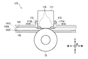
- the reading unit 176 replaces the thickness information acquisition unit 50, the optical information acquisition unit 60, and the magnetic information acquisition unit 70 with a thickness information acquisition unit 150, an optical information acquisition unit 160, and a magnetic information acquisition unit, respectively.
- a portion 170 is provided.
- a driving roller 44F is attached to the upper side of the rear rear conveyance guide 82 so as to be rotatable about the left-right direction.
- the drive roller 44F projects a part of the outer peripheral surface into the conveyance path 143 from an opening formed in the rear rear conveyance guide surface 82S.
- a drive roller 44G is attached to the upper side of the lower discrimination conveyance guide 142 so as to be rotatable about the left-right direction.
- the drive roller 44G projects a part of the outer peripheral surface into the conveyance path 143 from an opening formed in the discrimination lower conveyance guide surface 142S.
- a driving roller 44H is attached to the rear side of the rear front conveyance guide 84 so as to be rotatable about the left-right direction.
- the drive roller 44H projects a part of the outer peripheral surface into the transport path 143 from an opening formed in the rear front transport guide surface 84S.
- Driven rollers 45F and 45G are attached to the lower side of the discrimination upper conveyance guide 141 so as to be rotatable about the left and right direction and movable in the vertical direction.
- the driven rollers 45 ⁇ / b> F and 45 ⁇ / b> G project a part of their outer peripheral surfaces into the conveyance path 143 from an opening formed in the discrimination upper conveyance guide surface 141 ⁇ / b> S.
- a driven roller 45H is attached to the front side of the rear rear conveyance guide 82 so as to be rotatable about the left-right direction and movable in the front-rear direction.
- the driven roller 45H projects a part of the outer peripheral surface into the conveyance path 143 from an opening formed in the rear rear conveyance guide surface 82S.
- the driving rollers 33A, 33B, 33C, 44A, 44B, 44C, 44F, 44G and 44H, the thickness reference roller 51, and the magnetic gap roller 73 are rotated by a driving force transmitted from an actuator (not shown).
- the driven rollers 34A, 45D, 45E, 45A, 45B, 45C, 45F, 45G and 45H and the thickness detection roller unit 52 are driven by the rotation of the rollers while pressing the bills BL against the rollers facing each other. Rotate.
- the discrimination part 118 conveys the banknote BL along the conveyance path 143.
- the distribution mechanism 86 as the second distribution mechanism is a blade whose front end faces rearward, and has an upper distribution surface 86A on the upper end surface and a lower distribution surface 86B on the lower end surface, and a rotation shaft 86C. A plurality of left and right directions are attached to the lower transport frame 139A so as to be rotatable about the center.
- the sorting mechanism 86 is configured to change the inclination direction of the blade by rotating by an actuator (not shown) to switch the banknote transport path in two ways.
- the distribution mechanism 86 changes the inclination direction of the blade to form a conveyance path connecting the discrimination part rear conveyance path 143G and the discrimination sensor conveyance path 143A, or the discrimination part rear conveyance path 143G and the storage side conveyance path A conveyance path connecting 143E is formed.
- the sorting mechanism 86 in the branching portion 143F, uses the upper sorting surface 86A to transfer the bills BL conveyed from the rear to the front in the discrimination portion rear side conveyance path 143G to the discrimination sensor conveyance path 143A or discrimination.
- the bills BL transported from the front to the rear in the sensor transport path 143A are distributed to the discrimination section rear transport path 143G.
- the sorting mechanism 86 uses the lower sorting surface 86B to transfer the banknote BL conveyed from the rear part forward conveyance path 143G from the rear to the front toward the storage side transport path 143E or the storage side transport.
- the banknote BL conveyed in the path 143E from the lower side to the upper side is distributed to the discrimination part rear side conveyance path 143G.
- the thickness information acquisition unit 150 includes a thickness detection roller unit 52, a gap sensor 55, a thickness sensor frame 153, and a thickness reference roller 51.
- the thickness detection roller portion 52, the gap sensor 55, and a biasing member (not shown) that presses the thickness detection roller portion 52 against the thickness reference roller 51 are attached to the thickness sensor frame 153.
- the thickness sensor frame 153 has a box-like shape with an open bottom, a thickness sensor attachment portion 153A that protrudes forward from the lower end portion on the front side, and a thickness sensor attachment portion that protrudes rearward from the lower end portion on the rear side. 153B is formed.
- the discrimination upper conveyance guide 141 includes a thickness sensor attachment portion 141F and a thickness sensor attachment portion 141G that protrude upward from the plate-like portion extending in the front-rear direction toward the thickness sensor attachment portion 153A and the thickness sensor attachment portion 153B, respectively. Is formed.
- the discrimination upper conveyance guide 141 can be attached to and detached from the thickness sensor mounting portion 141F and the thickness sensor mounting portion 153B to the thickness sensor mounting portion 141G by a thickness sensor fixing member 154 such as a screw, respectively. It is fixed to.
- the optical information acquisition unit 160 includes a reflection / transmission sensor unit 161U located on the upper side and a reflection sensor unit 161D located on the lower side.
- the reflection / transmission sensor unit 161U and the reflection sensor unit 161D have the same configuration of the reflection sensor unit, and are disposed to face each other up and down across the identification sensor transport path 143A.
- the reflection / transmission sensor unit 161U will be mainly described, and the description of the reflection sensor unit 161D will be omitted.
- a member having “D” at the end of the reference numeral in the reflection sensor unit 161D is a member having the same numeral as that of the reflection sensor unit 161D and having “U” at the end in the reflection / transmission sensor unit 161U. It corresponds.
- the reflection / transmission sensor unit 161U has an optical sensor case 162U.
- the optical sensor case 162U has a box shape with an open bottom, and includes an optical sensor mounting portion 162AU that protrudes forward from the lower end portion on the front side and an optical sensor mounting portion 162BU that protrudes rearward from the lower end portion on the rear side. Has been.
- the discrimination upper conveyance guide 141 is formed with an optical sensor mounting portion 141D and an optical sensor mounting portion 141E that protrude upward from a plate-like portion extending in the front-rear direction toward the optical sensor mounting portion 162AU and the optical sensor mounting portion 162BU, respectively. .
- the discrimination upper conveyance guide 141 is detachably fixed to the optical sensor mounting portion 141D and the optical sensor mounting portion 162BU to the optical sensor mounting portion 141E by an optical sensor fixing member 167U such as a screw. .
- An optical sensor sealing member 168U is provided between the optical sensor case 162U and the discrimination upper conveyance guide 141.
- the reflection / transmission sensor unit 161U is crushed so that the optical sensor sealing member 168U is crushed between the optical sensor case 162U and the discrimination upper conveyance guide 141. Fill the gap. For this reason, the reflection / transmission sensor unit 161U can prevent intrusion of dust from the outside to the inside.
- the discrimination lower conveyance guide 142 is attached to and detached from the optical sensor mounting portion 142D of the reflection sensor unit 161D and the optical sensor mounting portion 162BD to and from the optical sensor mounting portion 142E by an optical sensor fixing member 167D such as a screw. It is fixed as possible.
- the magnetic information acquisition unit 170 includes a magnetic sensor 171 and a magnetic gap roller 73.
- the magnetic sensor 171 includes a magnetic sensor mounting portion 171A that protrudes forward from the lower end portion on the front side, and a magnetic sensor mounting portion 171B that protrudes rearward from the lower end portion on the rear side.
- the discrimination upper conveyance guide 141 is formed with a magnetic sensor attachment portion 141A and a magnetic sensor attachment portion 141B that protrude upward from the plate-like portion extending in the front-rear direction toward the magnetic sensor attachment portion 171A and the magnetic sensor attachment portion 171B, respectively. .
- the discrimination upper conveyance guide 141 is detachably fixed to the magnetic sensor mounting portion 141A and the magnetic sensor mounting portion 171B to the magnetic sensor mounting portion 141B by a magnetic sensor fixing member 172 such as a screw. .
- a magnetic sensor sealing member 175 is provided between the magnetic sensor 171 and the discrimination upper conveyance guide 141.
- the magnetic sensor 171 is pressed against the discrimination upper transport guide 141 by the magnetic sensor fixing member 172, the magnetic sensor 171 is crushed and the gap between the magnetic sensor 171 and the discrimination upper transport guide 141 is increased. fill in. Therefore, the magnetic sensor 171 can prevent dust from entering from the outside to the inside.
- the reflection / transmission sensor unit 161U or the reflection sensor unit 161D is replaced with a sensor having a higher resolution or a sensor capable of acquiring image information of a different wavelength.
- the operator removes the optical sensor fixing member 167 and replaces the reflection / transmission sensor unit 161U or the reflection sensor unit 161D.
- the optical sensor fixing member 167 is removed from the optical sensor sealing member 168. Thereby, the sealing state of the optical sensor sealing member 168 is released.
- the optical sensor case 162U is pressed against the discrimination upper conveyance guide 141 by the optical sensor fixing member 167U, so that the reflection / transmission sensor unit 161U is sealed again.
- the optical sensor case 162D is pressed against the discrimination lower conveyance guide 142 by the optical sensor fixing member 167D, and thus the reflection sensor unit 161D is sealed again.
- the optical information acquisition unit 160 can easily release the sealed state and return it to the sealed state. Therefore, it is possible to prevent the performance degradation caused by the dust entering the inside and erroneously detecting the dust. .
- the operator When repairing the magnetic information acquisition unit 170 (FIG. 13) when an abnormality occurs or when replacing the magnetic sensor 171 with a sensor having higher resolution or accuracy, the operator removes the magnetic sensor fixing member 172 and removes the magnetic sensor 171. Replace.
- the magnetic sensor sealing member 175 is pressed against the upper conveyance guide 141 by the magnetic sensor fixing member 172. Therefore, when the magnetic sensor fixing member 172 is removed, the magnetic sensor sealing member 175 is pressed. The sealed state of 175 is released. After replacement of the magnetic sensor 171, the magnetic sensor 171 is pressed again by the magnetic sensor fixing member 172 against the discrimination upper conveyance guide 141, so that the magnetic sensor 171 is sealed again.
- the magnetic information acquisition unit 170 can easily release the sealed state and return it to the sealed state. Therefore, the magnetic information acquiring unit 170 is generated when dust such as magnetic ink enters the inside and erroneously detects the magnetic ink or the like. Performance degradation can be prevented.
- the discrimination unit 118 forms a discrimination sensor conveyance path 143A as a discrimination part conveyance path through which the banknote BL is conveyed, and is provided with a reading unit 176 that reads the characteristics of the banknote BL in the discrimination sensor conveyance path 143A.
- the discrimination sensor unit 140 and the discrimination sensor unit 140 are detachably fixed.
- the discrimination sensor transport path 143A is connected to the discrimination sensor unit 140 and the discrimination sensor transport path.
- the discrimination connection conveyance part 130 which forms the discrimination part rear side conveyance path 143G as a conveyance part conveyance path which conveys banknote BL in the same front-back direction as 143A was provided.
- the discrimination part 18 (FIG. 3) conveys the banknote BL in the direction where the deposit / withdrawal part side conveyance path 43C and the rejection store
- the rear part conveyance path 143G is configured to convey the banknote BL in the same direction as the identification sensor conveyance path 43A.
- the discrimination part 118 was made to include even the connection part of the conveyance part 24 and the banknote storage 26A. For this reason, since the discrimination part 118 can open
- the thickness sensor frame 153 of the thickness information acquisition unit 150 is integrated with a part of the discrimination unit frame 149.
- this conventional discrimination unit is difficult to disassemble, it is necessary to remove the thickness detection roller unit 52 and the gap sensor 55 of the thickness information acquisition unit 150 individually, and the operator can easily replace them. There wasn't.
- the conventional optical information acquisition unit 160 there is an object that uses an adhesive to seal the reflection / transmission sensor unit 161U and the reflection sensor unit 161D.
- the discrimination sensor unit 140 of the discrimination unit 118 includes a thickness sensor frame 153 of the thickness information acquisition unit 150, a reflection / transmission sensor unit 161U and a reflection sensor unit 161D of the optical information acquisition unit 160, and a magnetic information acquisition unit 170.
- the magnetic sensor 171 is detachably attached to the discrimination upper conveyance guide 141 or the discrimination lower conveyance guide 142. Thereby, the discrimination part 118 can make an operator replace
- the discrimination unit 118 according to the second exemplary embodiment exhibits substantially the same operational effects as the discrimination unit 18 according to the first exemplary embodiment.
- the distribution mechanism 86 is attached to the lower conveyance frame 139A.
- the present disclosure is not limited to this, and the sorting mechanism 86 may be attached to the discrimination upper frame 149A.
- the sorting mechanism 86 moves together with the discrimination upper frame 149A in the open state, the visibility of the storage-side transport path 143E can be improved.
- the discrimination sensor unit 40 that causes the bills to run in the front-rear direction along the substantially horizontal discrimination sensor conveyance path 43A, the substantially vertical deposit / withdrawal part side conveyance path 43C, and the reject storage.
- the case where the present disclosure is applied to the differential connection transport unit 30 that travels bills in the vertical direction along the side transport path 43D has been described.
- the present disclosure is not limited to this, and is disclosed in a discrimination sensor unit that travels banknotes along a differential sensor transport path along various directions, and a differential connection transport unit that travels banknotes in a direction different from the differential sensor transport path. May be applied.
- the conveyance path of the conveyance unit 24 branches to the banknote storage 26A from the branch unit 43B where the conveyance path of the conveyance unit 24 branches to the deposit / withdrawal unit 16 or the reject storage 28.
- the present disclosure is not limited to this, and the conveyance path of the conveyance unit 24 is any one of the bill storage boxes 26B, 26C, 26D, and 26E from the branching portion where the conveyance path of the conveyance unit 24 branches to the deposit / withdrawal unit 16 or the reject storage 28. Up to the branching portion that branches to the discrimination portion 118 may be included.
- the present disclosure is not limited to this, but includes a pre-transportation frame 39B, an upper-discrimination frame 49A, a lower-discrimination frame 49B, and a lower-conveyance that include the lower-conveyance frame 39A in addition to the upper-discrimination frame 49A and lower-discrimination frame 49B
- the frame 39A may be provided so as to be detachable from a predetermined frame. The same applies to the second exemplary embodiment.
- the thickness information acquisition unit 50, the optical information acquisition unit 60, and the magnetic information acquisition unit 70 are sequentially arranged in the discrimination sensor unit 40 from the rear to the front. Said the case of placing.
- the present disclosure is not limited to this, and the thickness information acquisition unit 50, the optical information acquisition unit 60, and the magnetic information acquisition unit 70 may be arranged in the discrimination sensor unit 40 in any order.
- any of the thickness information acquisition unit 50, the optical information acquisition unit 60, and the magnetic information acquisition unit 70 may be omitted. The same applies to the second exemplary embodiment.
- the driving roller 44C and the driven roller 45C which are a pair of upper and lower rollers each having a plurality of rollers arranged at predetermined intervals in the left-right direction.
- the present disclosure is not limited to this, and a driving roller and a driven roller that are a pair of upper and lower rollers in which one roller is disposed in the left-right direction may be provided.
- the reading unit 176 in the second exemplary embodiment may be provided instead of the reading unit 76, and in the discrimination unit 118 according to the second exemplary embodiment. Instead of the reading unit 176, a reading unit 76 may be provided.
- the present disclosure is not limited to each exemplary embodiment described above and other exemplary embodiments. That is, the present disclosure is also applicable to an exemplary embodiment that arbitrarily combines some or all of the exemplary embodiments described above and the other exemplary embodiments described above, and an exemplary embodiment in which some are extracted. Range.
- the present disclosure is applied in the discrimination unit that discriminates banknotes as a medium in the automatic teller machines 1 and 101 that deal with cash has been described.
- the present disclosure is not limited to this, and may be applied to various devices that distinguish thin paper-like media such as receivables, certificates, gift certificates, cash vouchers, admission tickets, and the like.
- it is configured by a combination of a plurality of types of apparatuses that perform various processes related to transactions of banknotes and coins, such as banknote depositing and dispensing machines for depositing and unloading banknotes and sealing small bundle payment machines for sealing banknotes every predetermined number. You may apply this indication to a cash processing device.
- the present disclosure is applied to an automatic cash transaction apparatus that performs a deposit transaction and a withdrawal transaction is described, but the present invention is not limited to an apparatus that performs only one of a deposit transaction or a withdrawal transaction. The disclosure may apply.
- the discrimination unit 18 as the paper sheet processing apparatus is configured by the discrimination sensor unit 40 as the discrimination unit and the discrimination connection transport unit 30 as the transport unit has been described.
- the present disclosure is not limited to this, and the sheet processing apparatus may be configured by a discrimination unit having various other configurations and a transport unit.
- the present disclosure can also be used in various devices that discriminate paper-like media such as banknotes.
Landscapes
- Physics & Mathematics (AREA)
- General Physics & Mathematics (AREA)
- Health & Medical Sciences (AREA)
- General Health & Medical Sciences (AREA)
- Toxicology (AREA)
- Engineering & Computer Science (AREA)
- Mechanical Engineering (AREA)
- Inspection Of Paper Currency And Valuable Securities (AREA)
- Separation, Sorting, Adjustment, Or Bending Of Sheets To Be Conveyed (AREA)
- Feeding Of Articles By Means Other Than Belts Or Rollers (AREA)
Abstract
本開示は紙葉類が搬送される鑑別部搬送路を形成すると共に、該鑑別部搬送路に前記紙葉類の特徴を読み取る読取手段を設けた鑑別部と、前記鑑別部が着脱可能で、該鑑別部が取り付けられることにより、前記鑑別部との間に、前記鑑別部搬送路と接続され該鑑別部搬送路と異なる方向に前記紙葉類を搬送する搬送部搬送路を形成する搬送部と、を有する紙葉類処理装置を提供する。
Description
本開示は紙葉類処理装置及び紙葉類鑑別装置に関し、例えば紙幣等の媒体を投入して所望の取引を行う現金自動取引装置(ATM:Automatic Teller Machine)に適用可能な紙葉類処理装置及び紙葉類鑑別装置に関する。
従来、金融機関や店舗等で使用される現金自動取引装置等は、顧客との取引内容に応じて、例えば顧客に紙幣や硬貨等の現金を入金させ、また顧客へ現金を出金する。現金自動取引装置としては、例えば顧客との間で紙幣の授受を行う入出金部と、投入された紙幣の金種及び真偽を鑑別する鑑別部と、投入された紙幣を一時的に保留する一時保留部と、紙幣を搬送する搬送部と、金種毎に紙幣を格納する紙幣収納庫とを有するものがある(例えば、特開2013-205940号公報参照)。
このような現金自動取引装置においては、鑑別部を有する紙葉類処理装置と紙葉類鑑別装置全体とを小型化することが望まれている。
本開示は、小型化し得る紙葉類処理装置及び紙葉類鑑別装置を提供する。
本開示の第1の態様は、紙葉類処理装置であって、紙葉類が搬送される鑑別部搬送路を形成すると共に、該鑑別部搬送路に紙葉類の特徴を読み取る読取手段を設けた鑑別部と、鑑別部が着脱可能で、該鑑別部が取り付けられることにより、鑑別部との間に、鑑別部搬送路と接続され該鑑別部搬送路と異なる方向に紙葉類を搬送する搬送部搬送路を形成する搬送部とを有する。
また、本開示の第2の態様は、紙葉類鑑別装置であって、所定の搬送部に対し着脱可能で、紙葉類が搬送される鑑別部搬送路を形成すると共に、該鑑別部搬送路に紙葉類の特徴を読み取る読取手段を設け、搬送部に取り付けられることにより、搬送部との間に、鑑別部搬送路と接続され該鑑別部搬送路と異なる方向に紙葉類を搬送する搬送部搬送路を有する。
本開示の上記態様によれば、鑑別部搬送路と搬送部搬送路との間に受渡部を設けないことにより鑑別部搬送路の長さを短くできる。かくして本開示の上記態様は、小型化し得る紙葉類処理装置及び紙葉類鑑別装置を提供できる。
以下、発明を実施するための形態(以下例示的実施形態とする)について、図面を用いて説明する。なお各図は、本開示を十分に理解できる程度に概略的に示してあるに過ぎない。よって本開示は、図示例のみに限定されるものではない。また各図において、共通する構成要素や同様な構成要素については同一の符号を付し、それらの重複する説明を省略する。
[1.第1の例示的実施形態]
[1-1.現金自動取引装置の構成]
図1に外観を示すように、現金自動取引装置1は、箱状の筐体2を中心に構成されており、例えば金融機関等に設置され、顧客との間で入金取引や出金取引等の現金に関する取引を行う。筐体2は、その前側に顧客が対峙した状態で紙幣の投入やタッチパネルによる操作等をしやすい箇所に顧客応対部3が設けられている。
[1-1.現金自動取引装置の構成]
図1に外観を示すように、現金自動取引装置1は、箱状の筐体2を中心に構成されており、例えば金融機関等に設置され、顧客との間で入金取引や出金取引等の現金に関する取引を行う。筐体2は、その前側に顧客が対峙した状態で紙幣の投入やタッチパネルによる操作等をしやすい箇所に顧客応対部3が設けられている。
顧客応対部3は、カード入出口4、入出金口5、操作表示部6、テンキー7及びレシート発行口8が設けられており、顧客との間で現金や通帳等を直接やり取りすると共に、取引に関する情報の通知や操作指示の受付を行う。カード入出口4は、キャッシュカード等の各種カードが挿入又は排出される部分である。カード入出口4の奥側には、各種カードに磁気記録された口座番号等の読み取りを行うカード処理部(図示せず)が設けられている。入出金口5は、顧客が入金する紙幣が投入されると共に、顧客へ出金する紙幣が排出される部分である。操作表示部6は、取引に際して操作画面を表示するLCD(Liquid Crystal Display)と、取引の種類の選択、暗証番号や取引金額等を入力するタッチパネルとが一体化されている。テンキー7は、「0」~「9」の数字等の入力を受け付ける物理的なキーであり、暗証番号や取引金額等の入力操作時に用いられる。レシート発行口8は、取引処理の終了時に取引内容等を印字したレシートを発行する部分である。
筐体2内には、現金自動取引装置1全体を統轄制御する主制御部9や、紙幣に関する種々の処理を行う紙幣入出金機10等が設けられている。主制御部9は、CPU(Central Processing Unit)(図示せず)を中心に構成されており、ROM(Read Only Memory)、RAM(Random Access Memory)、ハードディスクドライブやフラッシュメモリ等でなる記憶部から所定のプログラムを読み出して実行することにより、各部を制御して入金取引や出金取引等の種々の処理を行う。
以下では、現金自動取引装置1のうち利用者が対峙する側を前側とし、その反対を後側とし、該前側に対峙した利用者から見て左及び右をそれぞれ左側及び右側とし、さらに上側及び下側を定義して説明する。
[1-2.紙幣入出金機の内部構成]
紙幣入出金機10は、図2に示すように、箱状の入出金機筐体11を中心に構成されており、制御部12が各部(入出金部16、鑑別部18、一時保留部20、偽券庫22、搬送部24、紙幣収納庫26及びリジェクト庫28)を統轄制御する。
紙幣入出金機10は、図2に示すように、箱状の入出金機筐体11を中心に構成されており、制御部12が各部(入出金部16、鑑別部18、一時保留部20、偽券庫22、搬送部24、紙幣収納庫26及びリジェクト庫28)を統轄制御する。
制御部12は、CPU(図示せず)を中心に構成されており、ROM、RAM、ハードディスクドライブやフラッシュメモリ等でなる記憶部14から所定のプログラムを読み出して実行することにより、各部を制御して入金取引や出金取引等の種々の処理を行う。
紙幣入出金機10の内部の上側には、入出金部16、紙幣の金種や真偽を判定する鑑別部18、入金紙幣等を一時的に保留する一時保留部20及び偽造紙幣(以下、偽券と呼ぶ)と判断された紙幣を収納する偽券庫22等が設けられている。
入出金部16は、入出金機筐体11内における前側上部に配され、顧客から投入された紙幣を1枚ずつ分離し搬送部24へ繰り出す。
搬送部24は、ローラやベルト等(図示せず)により、図中実線で示す搬送路に沿って長方形の紙幣を短手方向に搬送する。搬送部24は、鑑別部18を前後方向に挿通させるように紙幣を搬送し、該鑑別部18の後側と一時保留部20、紙幣収納庫26及び偽券庫22とをそれぞれ接続している。また搬送部24は、鑑別部18の前側と入出金部16及びリジェクト庫28とを接続している。搬送部24の分岐点には、セレクタ(図中三角形で示す)が設けられており、制御部12の制御に基づき回動することにより、紙幣の搬送先を切り替える。
鑑別部18は、その内部で紙幣を搬送しながら、光学素子や磁気検出素子等を用いて該紙幣の金種及び真偽、並びに損傷の程度等(正損)を鑑別し、その鑑別結果を制御部12へ通知する。また鑑別部18は、撮像した紙幣の画像データから記番号を読み取り識別し、その識別結果を制御部12へ通知する。これに応じて制御部12は、取得した鑑別結果及び識別結果に基づいて紙幣の搬送先を決定する。この鑑別部18は、後述する鑑別接続搬送部30と鑑別センサ部40とにより構成されている。
一時保留部20は、入出金機筐体11内における前後方向のほぼ中央部であって搬送部24の上に隣接する位置に配されている。一時保留部20は、いわゆるテープエスクロ方式を採用しており、円筒形状のドラムの周側面に紙幣をテープと共に巻き付けることで該紙幣を収納し、またこの周側面から該テープを引き剥がすことで紙幣を繰り出す。
偽券庫22は、入出金機筐体11内における後側上部であって搬送部24の上に隣接する位置に配され、内部に紙幣を収納する空間を有している。この偽券庫22は、鑑別部18及び制御部12により偽券と判断された紙幣が搬送部24により搬送されてくると、これを内部に収納する。
紙幣入出金機10の内部の下側には、再利用すべきでない紙幣を収納するリジェクト庫28と、再利用可能な紙幣を収納する5個の紙幣収納庫26とが設けられている。
リジェクト庫28は、入出金機筐体11内における前側下部に配され、上下方向に長い直方体状に形成されると共に内部に紙幣を集積して収納する空間を有している。このリジェクト庫28は、鑑別部18及び制御部12により損傷の程度が大きく再利用すべきで無いと判断された紙幣が搬送部24により搬送されて来ると、該紙幣を内部に収納する。
入出金機筐体11内におけるリジェクト庫28の後方には、前側から後側へ向けて順に5個の紙幣収納庫26(26A、26B、26C、26D及び26E)が設けられている。各紙幣収納庫26は、何れも同様に構成されており、上下方向に長い直方体状に形成されると共に内部に紙幣を集積して収納する空間を有している。各紙幣収納庫26は、それぞれ収納すべき紙幣の金種が予め設定されている。この紙幣収納庫26は、鑑別部18及び制御部12により損傷の程度が小さく再利用が可能であると判断された紙幣が、その金種に応じて搬送部24により搬送されてくると、該紙幣を内部に集積して収納する。また紙幣収納庫26は、制御部12から紙幣を繰り出す指示を受け付けると、集積している紙幣を1枚ずつに分離して繰り出し、搬送部24に受け渡す。
かかる構成において現金自動取引装置1は、鑑別部18による紙幣の鑑別結果及び識別結果等をもとに主制御部9及び制御部12が各部を制御して、紙幣の入金処理及び出金処理等を行う。
すなわち現金自動取引装置1は、入金取引時、顧客により操作表示部6を介して入金取引が選択され入出金部16に紙幣が投入されると、投入された紙幣を入出金部16から1枚ずつ鑑別部18に搬送して該鑑別部18内を搬送する。ここで現金自動取引装置1は、鑑別部18の鑑別結果及び識別結果に基づき入金可能と判定された入金可能紙幣については一時保留部20に搬送して一時的に収納する。一方で現金自動取引装置1は、入金に適さないと判定された入金リジェクト紙幣については入出金部16へ戻して顧客に返却する。その後顧客により入金金額が確定されると、現金自動取引装置1は、一時保留部20に収納している紙幣のうち収納可能と判定された紙幣については、その金種に応じて各紙幣収納庫26へ搬送して保管する。一方で現金自動取引装置1は、偽券と判定された紙幣については、偽券庫22へ搬送する。また現金自動取引装置1は、収納に適さないと判定された紙幣については、リジェクト庫28へ搬送する。
一方出金取引時、現金自動取引装置1は、顧客により操作表示部6を介して出金取引が選択され出金金額が入力されると、要求金額に応じて必要な金種毎の紙幣枚数を認識する。次に、現金自動取引装置1は、金種毎の紙幣枚数に応じて各紙幣収納庫26から紙幣を繰り出して鑑別部18に搬送して該鑑別部18内を搬送し、鑑別結果及び識別結果を得る。ここで現金自動取引装置1は、鑑別部18の鑑別結果及び識別結果に基づき出金可能と判定された出金可能紙幣については入出金部16に搬送する。一方で現金自動取引装置1は、出金に適さないと判定された出金リジェクト紙幣についてはリジェクト庫28へ搬送して収納する。そして要求金額分の紙幣が入出金部16へ集積されると、現金自動取引装置1は、シャッタを開ける。これにより入出金部16内に集積されている紙幣の受け取りが可能な状態となり、顧客がこの紙幣を受け取る。その後現金自動取引装置1は、一時保留部20に収納している出金リジェクト紙幣をリジェクト庫28へと搬送して保管する。
[1-3.鑑別部の構成]
図3に示すように、鑑別部18は、図4で示すL型形状の鑑別接続搬送部30と、図5で示す、鑑別接続搬送部30の後方上側に配され該鑑別接続搬送部30に着脱可能な直方体状の鑑別センサ部40とにより構成されている。ここで図3は、通常通り現金自動取引装置1が運用されている通常状態における鑑別部18を示している。
図3に示すように、鑑別部18は、図4で示すL型形状の鑑別接続搬送部30と、図5で示す、鑑別接続搬送部30の後方上側に配され該鑑別接続搬送部30に着脱可能な直方体状の鑑別センサ部40とにより構成されている。ここで図3は、通常通り現金自動取引装置1が運用されている通常状態における鑑別部18を示している。
鑑別接続搬送部30は、前後方向に延びる箱型の搬送下フレーム39Aと、該搬送下フレーム39Aの前方に配され上下方向に延びる箱型の搬送前フレーム39Bとを有している。鑑別センサ部40は、前後方向に延びる箱型の鑑別上フレーム49Aと、該鑑別上フレーム49Aの下方に配され前後方向に延びる箱型の鑑別下フレーム49Bとを有している。以下では搬送下フレーム39A及び搬送前フレーム39Bをまとめて搬送部フレーム39とも呼び、鑑別部第1フレームとしての鑑別上フレーム49A及び鑑別部第2フレームとしての鑑別下フレーム49Bをまとめて鑑別部フレーム49とも呼ぶ。この搬送下フレーム39A、搬送前フレーム39B、鑑別下フレーム49B及び鑑別上フレーム49Aは、鑑別部18内の各構成部品を支持するフレーム部材である。鑑別下フレーム49Bと鑑別上フレーム49Aの間と、鑑別下フレーム49Bと搬送前フレーム39Bとの間と、搬送下フレーム39Aと搬送前フレーム39Bとの間と、鑑別上フレーム49Aと搬送前フレーム39Bとの間とには、紙幣BLを搬送する搬送路43が設けられている。
鑑別上フレーム49Aは、前端部分に設けられた回動支点37を軸として後端が上方へ移動するよう回動可能に構成されている。鑑別上フレーム49Aは、搬送路43に詰まった紙幣が取り除かれる保守作業が行われる際、保守作業者により回動支点37を軸として回動されることにより、図3に示す通常状態から図6に示す開放状態となる。この結果、鑑別センサ搬送路43A(後述する)は、外部に開放され、保守作業者にアクセスし易い状態となる。
搬送下フレーム39Aは、前後方向に延びる上側の板状部分から鑑別下フレーム49Bの下側の板状部分に向かうよう上方に突出する鑑別センサ部取付箇所35A及び鑑別センサ部取付箇所35Bが形成されている。鑑別下フレーム49Bは、それぞれ鑑別センサ部取付箇所35Aにネジ等の鑑別センサ部固定部材46Aが、鑑別センサ部取付箇所35Bにネジ等の鑑別センサ部固定部材46Bが螺合することにより、搬送下フレーム39Aに着脱可能に固定されている。
搬送路43は、鑑別センサ搬送路43A、分岐部43B、入出金部側搬送路43C及びリジェクト庫側搬送路43Dにより構成されている。鑑別センサ搬送路43Aは、鑑別上フレーム49Aと鑑別下フレーム49Bとの間において、搬送路受渡部80Aから、分岐部43Bまで延びる。搬送路受渡部80Aは、鑑別センサ部40の後端において、搬送部24(図2)の鑑別部18の後方と紙幣を受け渡す箇所である。鑑別センサ搬送路43Aは、該搬送路受渡部80Aと該分岐部43Bとの間で紙幣BLを前後方向に走行させる。分岐部43Bは、鑑別上フレーム49Aと鑑別下フレーム49Bと搬送前フレーム39Bとの間において、鑑別センサ搬送路43Aの前端と入出金部側搬送路43Cの下端とリジェクト庫側搬送路43Dの上端との間に配されている。分岐部43Bは、鑑別センサ搬送路43Aの前端から鑑別センサ部40の上方と下方とに分岐する。搬送部第1搬送路としての入出金部側搬送路43Cは、鑑別上フレーム49Aと搬送前フレーム39Bとの間において、分岐部43Bから、入出金部側受渡部80Bまで延びる。入出金部側受渡部80Bは、鑑別センサ部40の上端において入出金部16と紙幣を受け渡す箇所である第1受渡部として機能する。入出金部側搬送路43Cは、該分岐部43Bと該入出金部側受渡部80Bとの間で紙幣BLを上下方向に走行させる。搬送部第2搬送路としてのリジェクト庫側搬送路43Dは、鑑別下フレーム49B及び搬送下フレーム39Aと搬送前フレーム39Bとの間において、分岐部43Bから、リジェクト庫受渡部80Cまで延びる。リジェクト庫受渡部80Cは、鑑別センサ部40の下端においてリジェクト庫28と紙幣を受け渡す箇所である。リジェクト庫側搬送路43Dは、該分岐部43Bと該リジェクト庫受渡部80Cとの間で紙幣BLを上下方向に走行させる。以下では入出金部側搬送路43C及びリジェクト庫側搬送路43Dをまとめて搬送部搬送路43CDとも呼ぶ。
紙幣入出金機10は、制御部12の制御に基づいて、紙幣BLを搬送路43に沿って入出金部側受渡部80Bから搬送路受渡部80Aへ、又は搬送路受渡部80Aから入出金部側受渡部80Bへ、又は搬送路受渡部80Aからリジェクト庫受渡部80Cへ走行させながら、紙幣BLの鑑別処理を行う。
鑑別部18は、搬送路43の周囲に、搬送下側搬送ガイド31、搬送前側搬送ガイド32、鑑別上側搬送ガイド41及び鑑別下側搬送ガイド42と、駆動ローラ33A、33B、33C、44A、44B及び44Cと、従動ローラ34A、45D、45E、45A、45B及び45Cと、振分機構36と、厚さ情報取得部50と、光学情報取得部60と、磁気情報取得部70とを有している。
搬送下側搬送ガイド31は、搬送下フレーム39Aの前端に設けられ紙幣をガイドするガイド部材である。搬送前側搬送ガイド32は、搬送前フレーム39Bの後端に設けられ搬送下側搬送ガイド31、鑑別上側搬送ガイド41及び鑑別下側搬送ガイド42と対向し紙幣をガイドするガイド部材である。鑑別部第1搬送ガイドとしての鑑別上側搬送ガイド41は、前後方向に沿って延び前端が上方に向かって湾曲する形状である。鑑別上側搬送ガイド41は、鑑別上フレーム49Aの前端及び下端に設けられ鑑別下側搬送ガイド42及び搬送前側搬送ガイド32と対向し紙幣をガイドするガイド部材である。鑑別部第2搬送ガイドとしての鑑別下側搬送ガイド42は、前後方向に沿って延び前端が下方に向かって湾曲する形状である。鑑別下側搬送ガイド42は、鑑別下フレーム49Bの前端及び上端に設けられ鑑別上側搬送ガイド41及び搬送前側搬送ガイド32と対向し紙幣をガイドするガイド部材である。以下では搬送下側搬送ガイド31及び搬送前側搬送ガイド32をまとめて搬送部搬送ガイドとも呼び、鑑別上側搬送ガイド41及び鑑別下側搬送ガイド42をまとめて鑑別部搬送ガイドとも呼ぶ。厚さ情報取得部50は紙幣BLの厚さ情報を、光学情報取得部60は紙幣BLの画像情報を、磁気情報取得部70は紙幣BLの磁気情報をそれぞれ取得する。以下では、厚さ情報取得部50、光学情報取得部60及び磁気情報取得部70をまとめて読取手段76とも呼ぶ。
搬送前側搬送ガイド32には、駆動ローラ33A、33B及び33Cが左右方向を軸に、すなわち紙幣BLの搬送方向と直交する方向に向けるよう、それぞれ左右方向に所定の間隔を空けて回転可能に取り付けられている。駆動ローラ33A、33B及び33Cは、それぞれの外周面の一部を搬送前側搬送ガイド面32Sに形成された開口部から搬送路43に突出させている。鑑別下側搬送ガイド42の上側には、駆動ローラ44A、44B及び44C並びに厚さ基準ローラ51が左右方向を軸にそれぞれ左右方向に所定の間隔を空けて回転可能に取り付けられている。また、磁気ギャップローラ73も左右方向を軸に回転可能で且つ上下方向に移動可能に左右方向に所定の間隔を空けて取り付けられている。鑑別下側搬送ガイド42の前側には、従動ローラ45Dが左右方向を軸に回転可能で且つ前後方向に移動可能に左右方向に所定の間隔を空けて取り付けられている。磁気ギャップローラ73、駆動ローラ44A、44B及び44C、厚さ基準ローラ51並びに従動ローラ45Dは、それぞれの外周面の一部を鑑別下側搬送ガイド面42Sに形成された開口部から搬送路43に突出させている。鑑別上側搬送ガイド41の下側には、従動ローラ45A、45B及び45Cが左右方向を軸に回転可能且つ上下方向に移動可能にそれぞれ左右方向に所定の間隔を空けて取り付けられている。鑑別上側搬送ガイド41の前側には、従動ローラ45Eが左右方向を軸に回転可能で且つ前後方向に移動可能に左右方向に所定の間隔を空けて取り付けられている。従動ローラ45A、45B、45C及び45Eは、それぞれの外周面の一部を鑑別上側搬送ガイド面41Sに形成された開口部から搬送路43内に突出させている。搬送下側搬送ガイド31には、従動ローラ34Aが左右方向を軸に回転可能且つ前後方向に移動可能にそれぞれ左右方向に所定の間隔を空けて取り付けられている。従動ローラ34Aは、外周面の一部を搬送下側搬送ガイド面31Sに形成された開口部から搬送路43に突出させている。従動ローラ34A、45D、45E、45A、45B及び45Cは、圧縮ばねである付勢部材(図示せず)により、それぞれ駆動ローラ33A、33B、33C、44A、44B及び44Cに押し付けられている。
厚さ情報取得部50は、厚さ検知ローラ部52と、ギャップセンサ55と、厚さ基準ローラ51とを有している。厚さ検知ローラ部52は、支点部52Aにおいて左右方向を軸に回動可能に鑑別上フレーム49Aに取り付けられている。厚さ検知ローラ部52のローラ部分は、外周面の一部を鑑別上側搬送ガイド面41Sに形成された開口部から搬送路43内に突出させている。厚さ検知ローラ部52のローラ部分は、回転支点部52Bにおいて左右方向を軸に回転可能に厚さ検知ローラブラケットに取り付けられている。厚さ検知ローラ部52は、圧縮ばねである付勢部材(図示せず)により、厚さ基準ローラ51に押し付けられている。ギャップセンサ55は、厚さ検知ローラ部52の上方に設けられている。ギャップセンサ55は、厚さ検知ローラ部52が厚さ基準ローラ51へ当接するときの位置を基準とし、厚さ検知ローラ部52の相対的な変位量を検出して、その検出結果を厚さ情報として制御部12へ送出する。制御部12は、この検出結果と予め記憶している厚さの基準値とを比較することにより、変位量が紙幣1枚分又は複数枚分の何れに相当するかを判定し、折れ曲がりや異物の貼り付け等の有無を判断する。
光学情報取得部60は、上側に位置する反射透過センサユニット61Uと下側に位置する反射センサユニット61Dとにより構成されている。反射透過センサユニット61Uと反射センサユニット61Dとは反射センサ部が同一の構成であり、鑑別センサ搬送路43Aを挟んで上下に対向して配置されている。以下では主に反射透過センサユニット61Uについて説明し、反射センサユニット61Dについての説明は省略する。また、反射センサユニット61Dにおいて符号の末尾に"D"が付された部材は、反射透過センサユニット61Uにおいて符号の数字が反射センサユニット61Dと同一であり末尾に"U"が付された部材と対応している。また符号の末尾に"U"又は"D"を付さずに記載する場合、反射透過センサユニット61U及び反射センサユニット61D両方の部材をまとめて示している。反射透過センサユニット61Uは、光学センサケース62Uを有している。光学センサケース62Uは、下方が開放された箱型形状であり、前側及び後側の下端部が鑑別上側搬送ガイド41に接着固定されている。光学情報取得部60は、紙幣BLの反射パターン及び透過パターンを検出し、その検出結果を画像情報として制御部12へ送出する。これに応じて制御部12は、光学情報取得部60から取得した紙幣BLの反射パターン及び透過パターンを用いて該紙幣BLの真偽や金種、或いは損傷の程度(正損)等を判定する。
磁気情報取得部70は、鑑別センサ搬送路43Aの上側において磁気センサ71が鑑別上側搬送ガイド41に固定されている。磁気ギャップローラ73は、その外周面と磁気センサ71の検出面との間に間隙を空けるように圧縮ばねである付勢部材(図示せず)により、リミッタ部材(図示せず)に押し付けられている。磁気情報取得部70は、磁気センサ71により、鑑別センサ搬送路43Aを搬送される紙幣BLの磁気を検出し、その検出結果を磁気情報として制御部12へ送出する。これに応じて制御部12は、磁気情報取得部70から取得した紙幣BLの磁気検出結果を用いて該紙幣の真偽や金種等を判定する。
駆動ローラ33A、33B、33C、44A、44B及び44C、厚さ基準ローラ51並びに磁気ギャップローラ73は、それぞれアクチュエータ(図示せず)から駆動力が伝達されることにより回転する。このとき、従動ローラ34A、45D、45E、45A、45B及び45C並びに厚さ検知ローラ部52は、それぞれ対向するローラに紙幣BLを押し付けながら、該ローラの回転に従動して回転する。これにより鑑別部18は、搬送路43に沿って紙幣BLを搬送する。
振分機構36は、先端が後方を向くブレードであり、上端面の上側振分面36Aと下端面の下側振分面36Bとを有し、回動軸36Cを中心に回動可能に左右方向に複数個が搬送前フレーム39Bに取り付けられている。振分機構36は、アクチュエータ(図示せず)によって回動することによりブレードの傾斜方向を変化させて紙幣の搬送経路を2通りに切り替えるように構成されている。振分機構36は、ブレードの傾斜方向を変化させ、鑑別センサ搬送路43Aと入出金部側搬送路43Cとを結ぶ搬送経路を形成するか、又は鑑別センサ搬送路43Aとリジェクト庫側搬送路43Dとを結ぶ搬送経路を形成する。これにより振分機構36は、分岐部43Bにおいて、上側振分面36Aにより、入出金部側搬送路43C内を上方から下方へ向けて搬送された紙幣BLを鑑別センサ搬送路43Aへ、又は鑑別センサ搬送路43A内を後方から前方へ向けて搬送された紙幣BLを入出金部側搬送路43Cへ振り分ける。一方、振分機構36は、下側振分面36Bにより、鑑別センサ搬送路43A内を後方から前方へ向けて搬送された紙幣BLをリジェクト庫側搬送路43Dへ振り分ける。
[1-4.鑑別部の動作]
鑑別部18は、入金処理を行う場合、制御部12の制御に基づき、アクチュエータ(図示せず)により振分機構36を駆動し先端が下方向を向くよう切り替えることにより、入出金部側搬送路43Cから鑑別センサ搬送路43Aへ紙幣BLが通過できるようにする。次に鑑別部18は、駆動ローラ33C、44C、44B及び44A、厚さ基準ローラ51並びに磁気ギャップローラ73にアクチュエータ(図示せず)により駆動力を伝達する。
鑑別部18は、入金処理を行う場合、制御部12の制御に基づき、アクチュエータ(図示せず)により振分機構36を駆動し先端が下方向を向くよう切り替えることにより、入出金部側搬送路43Cから鑑別センサ搬送路43Aへ紙幣BLが通過できるようにする。次に鑑別部18は、駆動ローラ33C、44C、44B及び44A、厚さ基準ローラ51並びに磁気ギャップローラ73にアクチュエータ(図示せず)により駆動力を伝達する。
紙幣BLが入出金部16から入出金部側受渡部80Bを介し鑑別部18に搬送されると、鑑別部18は、まず駆動ローラ33Cと従動ローラ45Eとで紙幣を挟み、従動ローラ45Eにより駆動ローラ33Cに該紙幣BLを押し付けて下方向への駆動力を伝達し、該紙幣BLを下方向に移動させ振分機構36に搬送する。紙幣BLは、振分機構36の上側振分面36Aに当たることにより、後方向に向きを変え、鑑別センサ搬送路43Aへ搬送される。
続いて鑑別部18は、駆動ローラ33C及び従動ローラ45Eの駆動力により紙幣BLを鑑別センサ搬送路43Aで後方向へ搬送し、該紙幣BLにより従動ローラ45Cを押し上げさせる。これにより鑑別部18は、駆動ローラ44Cと従動ローラ45Cとで紙幣を挟み、従動ローラ45Cにより駆動ローラ44Cに該紙幣BLを押し付けて後方向への駆動力を伝達し、該紙幣BLを磁気情報取得部70へ搬送する。続けて紙幣BLは、磁気情報取得部70の磁気ギャップローラ73の駆動力により、磁気センサ71の検出面と磁気ギャップローラ73との間に設けられた間隙を、詰まることなく搬送される。紙幣BLが磁気情報取得部70を通過している間、鑑別部18は、磁気情報取得部70により紙幣BL表面の磁気インク等の磁気情報を取得する。
続いて鑑別部18は、駆動ローラ44C及び従動ローラ45Cの駆動力により紙幣BLを後方向へ搬送し、該紙幣BLにより従動ローラ45Bを押し上げさせる。これにより鑑別部18は、駆動ローラ44Bと従動ローラ45Bとで紙幣を挟み、従動ローラ45Bにより駆動ローラ44Bに該紙幣BLを押し付けて後方向への駆動力を伝達し、該紙幣BLを光学情報取得部60へ搬送する。紙幣BLが光学情報取得部60に搬送され該光学情報取得部60を通過している間、鑑別部18は、光学情報取得部60により紙幣BL表面の反射画像や透過画像等の画像情報を取得する。
続いて鑑別部18は、駆動ローラ44B及び従動ローラ45Bの駆動力により紙幣BLを後方向へ搬送し、該紙幣BLにより従動ローラ45Aを押し上げさせる。これにより鑑別部18は、駆動ローラ44Aと従動ローラ45Aとで紙幣を挟み、従動ローラ45Aにより駆動ローラ44Aに該紙幣BLを押し付けて後方向への駆動力を伝達し、該紙幣BLを厚さ情報取得部50へ搬送する。続いて鑑別部18は、駆動ローラ44A及び従動ローラ45Aの駆動力により紙幣BLを後方向へ搬送し、該紙幣BLにより厚さ検知ローラ部52を押し上げさせる。これにより鑑別部18は、厚さ検知ローラ部52と厚さ基準ローラ51とで紙幣を挟み、厚さ検知ローラ部52により厚さ基準ローラ51に該紙幣BLを押し付けて後方向への駆動力を伝達する。紙幣BLが厚さ情報取得部50を通過している間、鑑別部18は、厚さ検知ローラ部52の動きの変化をギャップセンサ55により検出し、紙幣BLの厚さ情報を取得する。
その後鑑別部18は、厚さ検知ローラ部52及び厚さ基準ローラ51の駆動力により紙幣BLを後方向へ搬送し、搬送路受渡部80Aを介し鑑別部18の後方へ繰り出す。制御部12は、磁気情報取得部70、光学情報取得部60及び厚さ情報取得部50において取得された紙幣BLの情報を信号伝達手段(図示せず)により取得して紙幣BLの真贋や金種、汚損の度合い等を鑑別する。次に、制御部12は、鑑別結果に基づき、該紙幣BLを一時保留部20へ搬送して貯留するか、又は入出金部16へ搬送して返却する。
以上は入金処理時において紙幣BLが搬送される場合の動作について説明した。しかしながら、収納処理時において紙幣BLが一時保留部20から紙幣収納庫26又はリジェクト庫28に搬送される場合と、出金処理時において紙幣BLが紙幣収納庫26から入出金部16又はリジェクト庫28に搬送される場合、鑑別部18は、入金処理時に対して各ローラの回転方向を逆にすると共に振分機構36を適宜切り替える。
[1-5.効果等]
ここで、従来の紙幣入出金機としては、図3と対応する部材に同一符号を付した図15に示すように、鑑別部18(図3)に代えて鑑別部218と搬送部224とを設けたものがある。搬送部224は、直方体状でありフレーム211に着脱可能に構成されている。鑑別部218は、直方体状であり、搬送部224の後方に配されフレーム211に着脱可能に構成されている。鑑別部218と搬送部224との間には、該鑑別部218と該搬送部224との間で紙幣を受け渡す受渡部280Gが形成されている。
ここで、従来の紙幣入出金機としては、図3と対応する部材に同一符号を付した図15に示すように、鑑別部18(図3)に代えて鑑別部218と搬送部224とを設けたものがある。搬送部224は、直方体状でありフレーム211に着脱可能に構成されている。鑑別部218は、直方体状であり、搬送部224の後方に配されフレーム211に着脱可能に構成されている。鑑別部218と搬送部224との間には、該鑑別部218と該搬送部224との間で紙幣を受け渡す受渡部280Gが形成されている。
紙幣BLは、鑑別部218と搬送部224との間の受渡部280Gを通過する。ここで、光学情報取得部60や磁気情報取得部70において精度良く情報を取得するためには、紙幣BLの上下位置の違いによる情報のばらつきを低減することが望ましい。このため、鑑別部218の搬送路243の上下方向の幅は、紙幣BLがジャム(紙詰まり)とならない程度に狭くしておくことが望ましい。しかしながら、搬送部224と鑑別部218との上下方向の位置は、部品の製造ばらつき等により一致しない場合があるため、搬送路243の上下方向の幅を狭くすると、紙幣BLが受渡部280Gにおいてジャムとなる可能性がある。
また、鑑別部218及び搬送部224は、受渡部280Gが存在するために、駆動ローラ33B及び33Cと駆動ローラ44Cとの間の距離が長くなってしまう。このため、鑑別部218及び搬送部224は、受渡部280Gの前側に駆動ローラ234B及び従動ローラ245Bを配置する必要があったため、部品点数を削減できず複雑な構成となっていたと共に、前後方向の長さが長くなっていた。
これに対し、従来の紙幣入出金機として、図15と対応する部材に同一符号を付した図16に示すように、鑑別部218(図15)に代えて鑑別部318を設けたものがある。鑑別部318は鑑別部218と比べて、駆動ローラ44C及び従動ローラ45Cが省略されている。鑑別部318は、鑑別部218に対し駆動ローラ44C及び従動ローラ45Cが省略されているため、該駆動ローラ44C及び従動ローラ45Cが占めていた空間の分だけ前後方向の長さを鑑別部218よりも短くできる。
しかしながら鑑別部318及び搬送部224は、入金処理時において磁気情報取得部70の上流側の最近傍に配置される駆動ローラ234B及び従動ローラ245Bが、鑑別部318ではなく搬送部224に設けられることとなる。
一般に、磁気情報取得部70は、搬送部224を含まない鑑別部318単体でセンサ出力調整や検査を行っており、基本出力等の情報を記憶している。また磁気情報取得部70は、紙幣BLの微弱な磁気反応を検出できるようになっているため、極めて感度が高い。このため、鑑別部318及び搬送部224がフレーム211に装着され駆動ローラ234B及び従動ローラ245Bが回転した際に、搬送部224の駆動ローラ234Bや従動ローラ245Bの金属部分が着磁している場合や、金属製の異物が付着している場合は、磁気情報取得部70が磁気情報にノイズ成分として検出することとなる。したがって、鑑別部318単体でセンサ出力調整や検査した条件よりも、磁気情報の検出性能が悪化してしまう。
これに対し本開示の鑑別部18では、鑑別接続搬送部30と鑑別センサ部40とを組み合わせ、鑑別部218における駆動ローラ234B及び従動ローラ245Bと駆動ローラ44C及び従動ローラ45C(図15)とを兼用した機能を一対の駆動ローラ44C及び従動ローラ45C(図3)に集約した。その結果、本開示の鑑別部18では、駆動ローラ234B及び従動ローラ245Bを省略できるため、搬送路43の前後方向の長さを短くし、装置サイズを小さくできる。
また鑑別部18は、鑑別接続搬送部30と鑑別センサ部40とを着脱可能に構成するようにした。これにより鑑別部18は、従来の鑑別部218及び318のように鑑別センサ部40を容易に交換させ保守性を保つことができる。
また本開示の鑑別部18では、鑑別接続搬送部30と鑑別センサ部40とを組み合わせることにより、鑑別センサ搬送路43Aの上方に設けられた鑑別上側搬送ガイド41を、読取手段76よりも振分機構36から離隔する側である後方から振分機構36を介し入出金部側受渡部80Bまで分断されることなく一体に形成した。さらに、本開示の鑑別部18では、鑑別センサ搬送路43Aの下方に設けられた鑑別下側搬送ガイド42を、読取手段76よりも後方から振分機構36を介しリジェクト庫受渡部80Cまで分断されることなく一体に形成するようにした。このように鑑別部18は、受渡部を介することなく鑑別センサ搬送路43Aが入出金部側搬送路43C及びリジェクト庫側搬送路43Dに分岐する搬送路43を形成するようにした。これにより鑑別部18は、鑑別部218(図15)及び鑑別部318(図16)のような受渡部280Gを持たない構造となるため、ジャムを低減し、搬送品質を向上させることができると共に、搬送路43の前後方向の長さを短くし、装置サイズを小さくできる。
また鑑別部18は、磁気情報取得部70の上流側の駆動ローラ44C及び従動ローラ45Cを、鑑別接続搬送部30ではなく鑑別センサ部40に含むようにした。これにより鑑別部18は、鑑別センサ部40単体で検査した際に、該鑑別センサ部40内部に含まれ位置精度が保証された駆動ローラ44C及び従動ローラ45Cの状態を検出することができ、磁気情報の検出性能を向上させることができる。
以上の構成によれば鑑別部18は、紙葉類としての紙幣BLが搬送される鑑別部搬送路としての鑑別センサ搬送路43Aを形成すると共に、該鑑別センサ搬送路43Aに紙幣BLの特徴を読み取る読取手段76を設けた鑑別センサ部40と、鑑別センサ部40が着脱可能で、該鑑別センサ部40が取り付けられることにより、鑑別センサ部40との間に、鑑別センサ搬送路43Aと接続され該鑑別センサ搬送路43Aと異なる方向に紙幣BLを搬送する搬送部搬送路43CDを形成する鑑別接続搬送部30とを設けるようにした。
これにより鑑別部18は、従来の鑑別部218及び搬送部224と同様に鑑別センサ部40の保守性能と磁気情報取得部70の検出性能とを保ちつつ、鑑別センサ搬送路43Aと入出金部側搬送路43C及びリジェクト庫側搬送路43Dとの間に受渡部を設けないことにより、搬送路43の前後方向の長さを搬送路243よりも短くし装置の前後方向の長さを短くすると共に、紙幣のジャムの発生を軽減できる。
[2.第2の例示的実施形態]
[2-1.紙幣入出金機の構成]
図1と、図2と対応する部材に同一符号を付した図7とに示すように、第2の例示的実施形態による現金自動取引装置101の紙幣入出金機110は、第1の例示的実施形態による現金自動取引装置1の紙幣入出金機10と比べて、鑑別部118が鑑別部18と異なっているものの、それ以外は同様に構成されている。
[2-1.紙幣入出金機の構成]
図1と、図2と対応する部材に同一符号を付した図7とに示すように、第2の例示的実施形態による現金自動取引装置101の紙幣入出金機110は、第1の例示的実施形態による現金自動取引装置1の紙幣入出金機10と比べて、鑑別部118が鑑別部18と異なっているものの、それ以外は同様に構成されている。
[2-2.鑑別部の構成]
図3、図4及び図5それぞれと対応する部材に同一符号を付した図8、図9及び図10に示すように、鑑別部118は、U型形状の鑑別接続搬送部130(図9)と、該鑑別接続搬送部130の上方に配され該鑑別接続搬送部130に着脱可能な略直方体状の鑑別センサ部140(図10)とにより構成されている。ここで図8は、通常通り現金自動取引装置101が運用されている通常状態における鑑別部118を示している。
図3、図4及び図5それぞれと対応する部材に同一符号を付した図8、図9及び図10に示すように、鑑別部118は、U型形状の鑑別接続搬送部130(図9)と、該鑑別接続搬送部130の上方に配され該鑑別接続搬送部130に着脱可能な略直方体状の鑑別センサ部140(図10)とにより構成されている。ここで図8は、通常通り現金自動取引装置101が運用されている通常状態における鑑別部118を示している。
鑑別接続搬送部130は、鑑別接続搬送部30(図4)と比べて、搬送下フレーム139Aが、搬送下フレーム39Aの後端部が上方へ延設されたような形状となっていると共に、該搬送下フレーム139Aの後方に、上下方向に延びる箱型の搬送後フレーム139Cが配されている。鑑別センサ部140は、鑑別センサ部40(図5)と比べて、鑑別下フレーム149Bが鑑別下フレーム49Bよりも後方へ延在していると共に、鑑別上フレーム149Aが鑑別下フレーム49Bよりも後方へ延在し、後端部が鑑別下フレーム149Bの後端よりも後方に位置している。以下では搬送下フレーム139A、搬送前フレーム139B及び搬送後フレーム139Cをまとめて搬送部フレーム139とも呼び、鑑別下フレーム149B及び鑑別上フレーム149Aをまとめて鑑別部フレーム149とも呼ぶ。鑑別上フレーム149Aと鑑別下フレーム149Bとの間と、鑑別下フレーム149Bと搬送前フレーム139Bとの間と、搬送下フレーム139Aと搬送前フレーム139Bとの間と、鑑別上フレーム149Aと搬送前フレーム139Bとの間と、鑑別上フレーム149Aと搬送後フレーム139Cの間と、搬送後フレーム139Cと搬送下フレーム139Aとの間とには、紙幣BLを搬送する搬送路143が設けられている。鑑別部118は、鑑別部18よりも搬送部24の後方まで、すなわち搬送部24と紙幣収納庫26Aとの接続箇所まで含んだ構成となっている。
鑑別上フレーム149Aは、前端部分に設けられた回動支点137を軸として後端が上方へ移動するよう回動可能に構成されている。鑑別上フレーム149Aは、搬送路143に詰まった紙幣が取り除かれる保守作業が行われる際、保守作業者により回動支点137を軸として回動されることにより、図8に示す通常状態から図14に示す開放状態となる。この結果、鑑別センサ搬送路143A及び鑑別部後側搬送路143Gは、外部に開放され、保守作業者にアクセスし易い状態となる。
搬送下フレーム139Aは、前後方向に延びる上側の板状部分から鑑別下フレーム149Bの下側の板状部分に向かうよう上方に突出する鑑別センサ部取付箇所35A及び鑑別センサ部取付箇所35Bが形成されている。鑑別下フレーム149Bは、それぞれ鑑別センサ部取付箇所35Aにネジ等の鑑別センサ部固定部材46Aが、鑑別センサ部取付箇所35Bにネジ等の鑑別センサ部固定部材46Bが螺合することにより、搬送下フレーム139Aに着脱可能に固定されている。
搬送路143には、搬送路43(図3)と比べて、それぞれ鑑別センサ搬送路43A、分岐部43B、入出金部側搬送路43C及びリジェクト庫側搬送路43Dと対応する鑑別センサ搬送路143A、分岐部43B、入出金部側搬送路43C及びリジェクト庫側搬送路43Dに、収納庫側搬送路143E、分岐部143F及び鑑別部後側搬送路143Gが追加されている。鑑別センサ搬送路143Aは、鑑別上フレーム149Aと鑑別下フレーム149Bとの間において、分岐部43Bから分岐部143Fまで延びている。分岐部143Fは、鑑別上フレーム149Aと搬送後フレーム139Cと搬送下フレーム139Aとの間において、鑑別部後側搬送路143Gの前端と鑑別センサ搬送路143Aの後端と収納庫側搬送路143Eの上端との間に配されている。分岐部143Fは、鑑別部後側搬送路143Gの前端から前方と下方とに分岐する。収納庫側搬送路143Eは、搬送後フレーム139Cと搬送下フレーム139Aとの間において、分岐部143Fから、収納庫受渡部180Dまで延びる。収納庫受渡部180Dは、鑑別接続搬送部130の下端の後寄りにおいて紙幣収納庫26Aと紙幣を受け渡す箇所である。収納庫側搬送路143Eは、該分岐部143Fと該紙幣収納庫26Aとの間で紙幣BLを上下方向に走行させる。鑑別部後側搬送路143Gは、鑑別上フレーム149Aと搬送下フレーム139Aとの間において、搬送路受渡部180Aから、分岐部143Fまで延びている。搬送路受渡部180Aは、搬送部24における鑑別部118の後方と紙幣を受け渡す箇所である。このように搬送路143は、搬送路43よりも後方へ延在し、後方の搬送部24まで含んだ構成となっている。
紙幣入出金機110は、制御部12の制御に基づいて、紙幣BLを搬送路143に沿って入出金部側受渡部180Bから搬送路受渡部180Aへ、又は搬送路受渡部180Aから入出金部側受渡部180Bへ、又は搬送路受渡部180Aからリジェクト庫受渡部180Cへ、又は搬送路受渡部180Aから収納庫受渡部180Dへ、又は収納庫受渡部180Dから搬送路受渡部180Aへ走行させながら、紙幣BLの鑑別処理を行う。
鑑別部118は、鑑別部18と比べて、搬送路143の周囲に、それぞれ搬送下側搬送ガイド31、搬送前側搬送ガイド32、鑑別上側搬送ガイド41及び鑑別下側搬送ガイド42と、駆動ローラ33A、33B、33C、44A、44B及び44Cと、従動ローラ34A、45D、45E、45A、45B及び45Cと、振分機構36と、厚さ情報取得部50と、光学情報取得部60と、磁気情報取得部70と対応する、搬送下側搬送ガイド31、搬送前側搬送ガイド32、鑑別上側搬送ガイド141及び鑑別下側搬送ガイド142と、駆動ローラ33A、33B、33C、44A、44B及び44Cと、従動ローラ34A、45D、45E、45A、45B及び45Cと、振分機構36と、厚さ情報取得部150と、光学情報取得部160と、磁気情報取得部170とを有している。これと共に鑑別部118には、後方後側搬送ガイド82及び後方前側搬送ガイド84と、駆動ローラ44F、44G及び44Hと、従動ローラ45F、45G及び45Hと、振分機構86とが追加されている。
後方後側搬送ガイド82は、搬送後フレーム139Cの上端及び前端に設けられ紙幣をガイドするガイド部材である。後方前側搬送ガイド84は、搬送下フレーム139Aの後端に設けられ紙幣をガイドするガイド部材である。以下では、搬送下側搬送ガイド31、搬送前側搬送ガイド32、後方後側搬送ガイド82及び後方前側搬送ガイド84をまとめて搬送部搬送ガイドとも呼び、鑑別上側搬送ガイド141及び鑑別下側搬送ガイド142をまとめて鑑別部搬送ガイドとも呼ぶ。読取手段176は、読取手段76と比べて、それぞれ厚さ情報取得部50、光学情報取得部60及び磁気情報取得部70に代えて厚さ情報取得部150、光学情報取得部160及び磁気情報取得部170が設けられている。
後方後側搬送ガイド82の上側には、駆動ローラ44Fが左右方向を軸に回転可能に取り付けられている。駆動ローラ44Fは、外周面の一部を後方後側搬送ガイド面82Sに形成された開口部から搬送路143内に突出させている。鑑別下側搬送ガイド142の上側には、駆動ローラ44Gが左右方向を軸に回転可能に取り付けられている。駆動ローラ44Gは、外周面の一部を鑑別下側搬送ガイド面142Sに形成された開口部から搬送路143内に突出させている。後方前側搬送ガイド84の後側には、駆動ローラ44Hが左右方向を軸に回転可能に取り付けられている。駆動ローラ44Hは、外周面の一部を後方前側搬送ガイド面84Sに形成された開口部から搬送路143内に突出させている。鑑別上側搬送ガイド141の下側には、従動ローラ45F及び45Gが左右方向を軸に回転可能且つ上下方向に移動可能に取り付けられている。従動ローラ45F及び45Gは、それぞれの外周面の一部を鑑別上側搬送ガイド面141Sに形成された開口部から搬送路143内に突出させている。後方後側搬送ガイド82の前側には、従動ローラ45Hが左右方向を軸に回転可能で且つ前後方向に移動可能に取り付けられている。従動ローラ45Hは、外周面の一部を後方後側搬送ガイド面82Sに形成された開口部から搬送路143内に突出させている。
駆動ローラ33A、33B、33C、44A、44B、44C、44F、44G及び44H、厚さ基準ローラ51並びに磁気ギャップローラ73は、それぞれアクチュエータ(図示せず)から駆動力が伝達されることにより回転する。このとき、従動ローラ34A、45D、45E、45A、45B、45C、45F、45G及び45H並びに厚さ検知ローラ部52は、それぞれ対向するローラに紙幣BLを押し付けながら、該ローラの回転に従動して回転する。これにより鑑別部118は、搬送路143に沿って紙幣BLを搬送する。
第2振分機構としての振分機構86は、先端が後方を向くブレードであり、上端面の上側振分面86Aと下端面の下側振分面86Bとを有し、回動軸86Cを中心に回動可能に左右方向に複数個が搬送下フレーム139Aに取り付けられている。振分機構86は、アクチュエータ(図示せず)によって回動することによりブレードの傾斜方向を変化させて紙幣の搬送経路を2通りに切り替えるように構成されている。振分機構86は、ブレードの傾斜方向を変化させ、鑑別部後側搬送路143Gと鑑別センサ搬送路143Aとを結ぶ搬送経路を形成するか、鑑別部後側搬送路143Gと収納庫側搬送路143Eとを結ぶ搬送経路を形成する。これにより振分機構86は、分岐部143Fにおいて、上側振分面86Aにより、鑑別部後側搬送路143G内を後方から前方へ向けて搬送された紙幣BLを鑑別センサ搬送路143Aへ、又は鑑別センサ搬送路143A内を前方から後方へ向けて搬送された紙幣BLを鑑別部後側搬送路143Gへ振り分ける。一方、振分機構86は、下側振分面86Bにより、鑑別部後側搬送路143G内を後方から前方へ向けて搬送された紙幣BLを収納庫側搬送路143Eへ、又は収納庫側搬送路143E内を下方から上方へ向けて搬送された紙幣BLを鑑別部後側搬送路143Gへ振り分ける。
図11に示すように厚さ情報取得部150は、厚さ検知ローラ部52と、ギャップセンサ55と、厚さセンサフレーム153と、厚さ基準ローラ51とを有している。厚さ検知ローラ部52と、ギャップセンサ55と、厚さ検知ローラ部52を厚さ基準ローラ51に押圧する付勢部材(図示せず)とは、厚さセンサフレーム153に取り付けられている。厚さセンサフレーム153は、下方が開放された箱型形状であり、前側の下端部から前方に突出する厚さセンサ取付部153Aと、後側の下端部から後方に突出する厚さセンサ取付部153Bとが形成されている。
鑑別上側搬送ガイド141は、前後方向に延びる板状部分からそれぞれ厚さセンサ取付部153A及び厚さセンサ取付部153Bに向かうよう上方に突出する厚さセンサ取付部141F及び厚さセンサ取付部141Gが形成されている。鑑別上側搬送ガイド141は、ネジ等の厚さセンサ固定部材154により、それぞれ厚さセンサ取付部153Aを厚さセンサ取付部141Fに、厚さセンサ取付部153Bを厚さセンサ取付部141Gに着脱可能に固定している。
図12に示すように光学情報取得部160は、上側に位置する反射透過センサユニット161Uと下側に位置する反射センサユニット161Dとにより構成されている。反射透過センサユニット161Uと反射センサユニット161Dとは反射センサ部が同一の構成であり、鑑別センサ搬送路143Aを挟んで上下に対向して配置されている。以下では主に反射透過センサユニット161Uについて説明し、反射センサユニット161Dについての説明は省略する。また、反射センサユニット161Dにおいて符号の末尾に"D"が付された部材は、反射透過センサユニット161Uにおいて符号の数字が反射センサユニット161Dと同一であり末尾に"U"が付された部材と対応している。
反射透過センサユニット161Uは、光学センサケース162Uを有している。光学センサケース162Uは、下方が開放された箱型形状であり、前側の下端部から前方に突出する光学センサ取付部162AUと後側の下端部から後方に突出する光学センサ取付部162BUとが形成されている。
鑑別上側搬送ガイド141は、前後方向に延びる板状部分からそれぞれ光学センサ取付部162AU及び光学センサ取付部162BUに向かうよう上方に突出する光学センサ取付部141D及び光学センサ取付部141Eが形成されている。鑑別上側搬送ガイド141は、ネジ等の光学センサ固定部材167Uにより、それぞれ光学センサ取付部162AUを光学センサ取付部141Dに、光学センサ取付部162BUを光学センサ取付部141Eに着脱可能に固定している。
光学センサケース162Uと鑑別上側搬送ガイド141との間には、光学センサ封止部材168Uが設けられている。反射透過センサユニット161Uは、光学センサ固定部材167Uにより光学センサケース162Uが鑑別上側搬送ガイド141に押し付けられると、光学センサ封止部材168Uが潰されて光学センサケース162Uと鑑別上側搬送ガイド141との隙間を埋める。このため、反射透過センサユニット161Uは、外部から内部への塵埃の侵入を防止できる。
鑑別下側搬送ガイド142は、ネジ等の光学センサ固定部材167Dにより、それぞれ反射センサユニット161Dの光学センサ取付部162ADを光学センサ取付部142Dに、光学センサ取付部162BDを光学センサ取付部142Eに着脱可能に固定している。
図13に示すように磁気情報取得部170は、磁気センサ171と磁気ギャップローラ73とを有している。磁気センサ171は、前側の下端部から前方に突出する磁気センサ取付部171Aと、後側の下端部から後方に突出する磁気センサ取付部171Bとが形成されている。
鑑別上側搬送ガイド141は、前後方向に延びる板状部分からそれぞれ磁気センサ取付部171A及び磁気センサ取付部171Bに向かうよう上方に突出する磁気センサ取付部141A及び磁気センサ取付部141Bが形成されている。鑑別上側搬送ガイド141は、ネジ等の磁気センサ固定部材172により、それぞれ磁気センサ取付部171Aを磁気センサ取付部141Aに、磁気センサ取付部171Bを磁気センサ取付部141Bに着脱可能に固定している。
磁気センサ171と鑑別上側搬送ガイド141との間には、磁気センサ封止部材175が設けられている。磁気センサ171は、磁気センサ固定部材172により該磁気センサ171が鑑別上側搬送ガイド141に押し付けられると、磁気センサ封止部材175が潰されて該磁気センサ171と鑑別上側搬送ガイド141との隙間を埋める。このため、磁気センサ171は、外部から内部への塵埃の侵入を防止できる。
[2-3.鑑別部の動作]
かかる構成において、厚さ情報取得部150(図11)に異常発生時の修理を行う場合や、厚さ情報取得部150をより分解能の良いセンサに交換する場合、作業者は、厚さセンサ固定部材154を取り外し、厚さセンサフレーム153と、該厚さセンサフレーム153に設けられた厚さ検知ローラ部52とギャップセンサ55とを交換する。
かかる構成において、厚さ情報取得部150(図11)に異常発生時の修理を行う場合や、厚さ情報取得部150をより分解能の良いセンサに交換する場合、作業者は、厚さセンサ固定部材154を取り外し、厚さセンサフレーム153と、該厚さセンサフレーム153に設けられた厚さ検知ローラ部52とギャップセンサ55とを交換する。
光学情報取得部160(図12)に異常発生時の修理を行う際や、反射透過センサユニット161U又は反射センサユニット161Dをより解像度の高いセンサや、異なる波長の画像情報が取得できるセンサに交換する場合、作業者は、光学センサ固定部材167を取り外し、反射透過センサユニット161U又は反射センサユニット161Dを交換する。
このとき、光学センサ封止部材168は、光学センサ固定部材167により光学センサケース162が鑑別上側搬送ガイド141又は鑑別下側搬送ガイド142に押し付けられているため、光学センサ固定部材167が外されることにより、光学センサ封止部材168の封止状態が解除される。反射透過センサユニット161Uの交換後は、光学センサ固定部材167Uにより光学センサケース162Uが鑑別上側搬送ガイド141に押し付けられるため、該反射透過センサユニット161Uは、再度封止される。同様に反射センサユニット161Dの交換後は、光学センサ固定部材167Dにより光学センサケース162Dが鑑別下側搬送ガイド142に押し付けられるため、該反射センサユニット161Dは、再度封止される。
このように光学情報取得部160は、容易に封止状態を解除すると共に封止状態に戻すことができるため、塵埃が内部に侵入し塵埃を誤検出することにより発生する性能の低下を防止できる。
磁気情報取得部170(図13)に異常発生時の修理を行う際や、磁気センサ171をより分解能や精度の良いセンサに交換する場合、作業者は磁気センサ固定部材172を取り外し、磁気センサ171を交換する。
このとき、磁気センサ封止部材175は、磁気センサ固定部材172により磁気センサ171が鑑別上側搬送ガイド141に押し付けられているため、磁気センサ固定部材172が外されることにより、磁気センサ封止部材175の封止状態が解除される。磁気センサ171の交換後は、磁気センサ固定部材172により磁気センサ171が鑑別上側搬送ガイド141に押し付けられるため、磁気センサ171は再度封止される。
このように磁気情報取得部170は、容易に封止状態を解除すると共に封止状態に戻すことができるため、磁気インク等の塵埃が内部に侵入し磁気インク等を誤検出することにより発生する性能の低下を防止できる。
[2-4.効果等]
以上の構成において鑑別部118は、紙幣BLが搬送される鑑別部搬送路としての鑑別センサ搬送路143Aを形成すると共に、該鑑別センサ搬送路143Aに紙幣BLの特徴を読み取る読取手段176を設けた鑑別センサ部140と、鑑別センサ部140が着脱可能に固定され、該鑑別センサ部140が固定された際、鑑別センサ部140との間に、鑑別センサ搬送路143Aと接続され該鑑別センサ搬送路143Aと同じ前後方向に紙幣BLを搬送する搬送部搬送路としての鑑別部後側搬送路143Gを形成する鑑別接続搬送部130とを設けるようにした。ここで、鑑別部18(図3)は、入出金部側搬送路43C及びリジェクト庫側搬送路43Dが鑑別センサ搬送路43Aとは異なる方向に紙幣BLを搬送するが、鑑別部118は、鑑別部後側搬送路143Gが鑑別センサ搬送路43Aと同じ方向に紙幣BLを搬送するように構成されている。
以上の構成において鑑別部118は、紙幣BLが搬送される鑑別部搬送路としての鑑別センサ搬送路143Aを形成すると共に、該鑑別センサ搬送路143Aに紙幣BLの特徴を読み取る読取手段176を設けた鑑別センサ部140と、鑑別センサ部140が着脱可能に固定され、該鑑別センサ部140が固定された際、鑑別センサ部140との間に、鑑別センサ搬送路143Aと接続され該鑑別センサ搬送路143Aと同じ前後方向に紙幣BLを搬送する搬送部搬送路としての鑑別部後側搬送路143Gを形成する鑑別接続搬送部130とを設けるようにした。ここで、鑑別部18(図3)は、入出金部側搬送路43C及びリジェクト庫側搬送路43Dが鑑別センサ搬送路43Aとは異なる方向に紙幣BLを搬送するが、鑑別部118は、鑑別部後側搬送路143Gが鑑別センサ搬送路43Aと同じ方向に紙幣BLを搬送するように構成されている。
また鑑別部118は、搬送部24と紙幣収納庫26Aとの接続箇所まで含むようにした。このため鑑別部118は、開放状態において鑑別部18の鑑別センサ搬送路43Aよりも鑑別センサ搬送路143Aの広い範囲を外部に開放することができるため、より一層保守作業者にアクセスさせ易くでき、保守時の視認性を向上させ作業性を向上できる。
また従来の鑑別部においては、厚さ情報取得部150の厚さセンサフレーム153が、鑑別部フレーム149の一部と一体化している物があった。しかしながら、この従来の鑑別部では、分解が困難であるため、厚さ情報取得部150の厚さ検知ローラ部52とギャップセンサ55を個別に取り外す必要があり、作業者が交換することが容易でなかった。また従来の光学情報取得部160には、反射透過センサユニット161U及び反射センサユニット161Dの封止に接着剤を用いる物があった。しかしながら、この従来の光学情報取得部160では、分解に接着剤を除去する必要があり、分解が困難であるため、従来の光学情報取得部160では、反射透過センサユニット161U及び反射センサユニット161Dを作業者が交換することが容易でなかった。また従来の磁気情報取得部170には、磁気センサ171の封止に接着剤を用いる物があった。しかしながら、この従来の磁気情報取得部170では、分解に接着剤を除去する必要があり、分解が困難であるため、従来の磁気情報取得部170では、磁気センサ171を作業者が交換することが容易でなかった。
これに対し鑑別部118の鑑別センサ部140は、厚さ情報取得部150の厚さセンサフレーム153と、光学情報取得部160の反射透過センサユニット161U及び反射センサユニット161Dと、磁気情報取得部170の磁気センサ171とを、鑑別上側搬送ガイド141又は鑑別下側搬送ガイド142に対し着脱可能に取り付けられるようにした。これにより鑑別部118は、異常発生時の修理を行う際や、性能の異なるセンサに変更する場合に、作業者に容易にセンサを交換させることができる。
その他第2の例示的実施形態による鑑別部118は、第1の例示的実施形態による鑑別部18とほぼ同様の作用効果を奏する。
[3.他の例示的実施形態]
なお上述した例示的実施形態においては、振分機構36を搬送前フレーム39Bに取り付ける場合について述べた。本開示はこれに限らず振分機構36を搬送下フレーム39Aに取り付けても良い。
なお上述した例示的実施形態においては、振分機構36を搬送前フレーム39Bに取り付ける場合について述べた。本開示はこれに限らず振分機構36を搬送下フレーム39Aに取り付けても良い。
また上述した第2の例示的実施形態においては、振分機構86を搬送下フレーム139Aに取り付ける場合について述べた。本開示はこれに限らず振分機構86を鑑別上フレーム149Aに取り付けても良い。この場合、開放状態において振分機構86が鑑別上フレーム149Aと共に移動するため、収納庫側搬送路143Eの視認性を向上できる。
さらに上述した第1の例示的実施形態においては、ほぼ水平な鑑別センサ搬送路43Aに沿って紙幣を前後方向へ走行させる鑑別センサ部40と、ほぼ鉛直な入出金部側搬送路43C及びリジェクト庫側搬送路43Dに沿って紙幣を上下方向へ走行させる鑑別接続搬送部30とに本開示を適用する場合について述べた。本開示はこれに限らず、種々の方向に沿う鑑別センサ搬送路に沿って紙幣を走行させる鑑別センサ部と、該鑑別センサ搬送路と異なる方向に紙幣を走行させる鑑別接続搬送部とに本開示を適用しても良い。第2の例示的実施形態においても同様である。
さらに上述した第2の例示的実施形態においては、搬送部24の搬送路が入出金部16又はリジェクト庫28へ分岐する分岐部43Bから、搬送部24の搬送路が紙幣収納庫26Aへ分岐する分岐部143Fまでを鑑別部118に含める場合について述べた。本開示はこれに限らず、搬送部24の搬送路が入出金部16又はリジェクト庫28へ分岐する分岐部から、搬送部24の搬送路が紙幣収納庫26B、26C、26D又は26Eの何れかへ分岐する分岐部までを鑑別部118に含めても良い。
さらに上述した第1の例示的実施形態においては、鑑別上フレーム49A及び鑑別下フレーム49Bを鑑別センサ部40に含め、搬送下フレーム39A及び搬送前フレーム39Bを鑑別接続搬送部30に含める場合について述べた。本開示はこれに限らず、鑑別上フレーム49A及び鑑別下フレーム49Bに加えて搬送下フレーム39Aを鑑別センサ部40に含める、搬送前フレーム39Bと、鑑別上フレーム49A、鑑別下フレーム49B及び搬送下フレーム39Aとが、所定のフレームに対し着脱可能に設けられていても良い。第2の例示的実施形態においても同様である。
さらに上述した第1の例示的実施形態においては、鑑別センサ部40の内部に、後方から前方へ向かって厚さ情報取得部50、光学情報取得部60及び磁気情報取得部70の順に読取手段76を配置する場合について述べた。本開示はこれに限らず、厚さ情報取得部50、光学情報取得部60及び磁気情報取得部70を任意の順番で鑑別センサ部40の内部に配置して良い。また厚さ情報取得部50、光学情報取得部60及び磁気情報取得部70は、何れかが省略されていても良い。第2の例示的実施形態においても同様である。
さらに上述した例示的実施形態においては、左右方向に所定の間隔を空けてそれぞれ複数個のローラが配された上下一対のローラである駆動ローラ44C及び従動ローラ45Cを設ける場合について述べた。本開示はこれに限らず、左右方向に1個のローラが配された上下一対のローラである駆動ローラ及び従動ローラを設けても良い。
さらに上述した第1の例示的実施形態による鑑別部18において読取手段76に代えて第2の例示的実施形態における読取手段176を設けても良く、第2の例示的実施形態による鑑別部118において読取手段176に代えて読取手段76を設けても良い。さらに本開示は、上述した各例示的実施形態及び他の例示的実施形態に限定されるものではない。すなわち本開示は、上述した各例示的実施形態と上述した他の例示的実施形態の一部又は全部を任意に組み合わせた例示的実施形態や、一部を抽出した例示的実施形態にもその適用範囲が及ぶものである。
さらに上述した例示的実施形態においては、現金を取引する現金自動取引装置1及び101において、媒体としての紙幣を鑑別する鑑別部において本開示を適用する場合について述べた。本開示はこれに限らず、例えば債権、証書、商品券、金券や入場券等のような薄い紙状の媒体を鑑別する種々の装置に適用しても良い。
また、例えば紙幣を入出する紙幣入出金機や紙幣を所定枚数毎に施封する施封小束支払機等、紙幣や硬貨の取引に関する種々の処理を行う複数種類の装置の組み合わせにより構成された現金処理装置に本開示を適用してもよい。
さらに上述した例示的実施形態においては、入金取引及び出金取引を行う現金自動取引装置に本開示を適用する場合について述べたが、入金取引又は出金取引の何れか一方のみを行う装置に本開示を適用しても良い。
さらに上述した例示的実施形態においては、鑑別部としての鑑別センサ部40と、搬送部としての鑑別接続搬送部30とによって、紙葉類処理装置としての鑑別部18を構成する場合について述べた。本開示はこれに限らず、その他種々の構成でなる鑑別部と、搬送部とによって、紙葉類処理装置を構成しても良い。
本開示は、紙幣等の紙状の媒体を鑑別する種々の装置でも利用できる。
日本出願特願2015-149614の開示は、その全体が参照により本明細書に取り込まれる。
本明細書に記載された全ての文献、特許出願、および技術規格は、個々の文献、特許出願、および技術規格が参照により取り込まれることが具体的かつ個々に記された場合と同程度に、本明細書中に参照により取り込まれる。
Claims (14)
- 紙葉類が搬送される鑑別部搬送路を形成すると共に、該鑑別部搬送路に前記紙葉類の特徴を読み取る読取手段を設けた鑑別部と、
前記鑑別部が着脱可能で、該鑑別部が取り付けられることにより、前記鑑別部との間に、前記鑑別部搬送路と接続され該鑑別部搬送路と異なる方向に前記紙葉類を搬送する搬送部搬送路を形成する搬送部と
を有する紙葉類処理装置。 - 前記鑑別部は、前記鑑別部搬送路を形成する鑑別部フレームを有し、
前記搬送部は、前記搬送部搬送路を形成する搬送部フレームを有し、
前記搬送部搬送路は、前記鑑別部フレームに設けられた鑑別部搬送ガイドと前記搬送部フレームに設けられた搬送部搬送ガイドとにより形成される
請求項1に記載の紙葉類処理装置。 - 前記紙葉類の搬送方向を前記鑑別部搬送路から分岐する前記搬送部搬送路のうちの搬送部第1搬送路又は搬送部第2搬送路の何れかへ振り分ける振分機構をさらに有する、請求項2に記載の紙葉類処理装置。
- 前記鑑別部フレームは、前記鑑別部搬送路の一方に設けられ、該鑑別部搬送路から前記搬送部第1搬送路にかけて一体に形成された鑑別部第1搬送ガイドが設けられた鑑別部第1フレームと、前記鑑別部搬送路の他方に設けられ、該鑑別部搬送路から前記搬送部第2搬送路にかけて一体に形成された鑑別部第2搬送ガイドが設けられた鑑別部第2フレームとを有し、
前記搬送部搬送ガイドは、前記搬送部第1搬送路及び前記搬送部第2搬送路を介し前記鑑別部第1搬送ガイド及び前記鑑別部第2搬送ガイドと対向する
請求項3に記載の紙葉類処理装置。 - 前記振分機構と前記読取手段との間に設けられるローラは、前記紙葉類を搬送する一対のローラのみである、請求項3に記載の紙葉類処理装置。
- 前記振分機構は、前記搬送部に設けられる、請求項3に記載の紙葉類処理装置。
- 前記鑑別部フレームは、前記鑑別部搬送路の一方に設けられ、該鑑別部搬送路と接続される鑑別部後側搬送路から、該鑑別部搬送路を介し前記搬送部第1搬送路にかけて一体に形成された鑑別部第1搬送ガイドが設けられた鑑別部第1フレームと、前記鑑別部搬送路の他方に設けられ、該鑑別部搬送路から前記搬送部第2搬送路にかけて一体に形成された鑑別部第2搬送ガイドが設けられた鑑別部第2フレームとを有し、
前記搬送部搬送ガイドは、前記搬送部第1搬送路及び前記搬送部第2搬送路を介し前記鑑別部第1搬送ガイド及び前記鑑別部第2搬送ガイドと対向し、前記鑑別部後側搬送路を介し前記鑑別部第1搬送ガイドと対向する
請求項3に記載の紙葉類処理装置。 - 前記鑑別部後側搬送路は、前記鑑別部搬送路と同じ方向に前記紙葉類を搬送する、請求項7に記載の紙葉類処理装置。
- 前記紙葉類の搬送方向を前記鑑別部後側搬送路から前記鑑別部搬送路又は所定の収納庫側搬送路の何れかへ振り分ける第2振分機構をさらに有する、請求項7に記載の紙葉類処理装置。
- 前記鑑別部第1フレームは、軸を中心に回動可能である、請求項4に記載の紙葉類処理装置。
- 前記搬送部搬送路の端部には、外部と前記紙葉類を受け渡す第1受渡部が形成されている、請求項4に記載の紙葉類処理装置。
- 前記読取手段は、前記鑑別部に対して着脱可能に取り付けられる、請求項1に記載の紙葉類処理装置。
- 前記読取手段は、厚さ情報取得部、光学情報取得部及び磁気情報取得部の何れか、又は複数の組み合わせである、請求項1に記載の紙葉類処理装置。
- 所定の搬送部に対し着脱可能で、紙葉類が搬送される鑑別部搬送路を形成すると共に、該鑑別部搬送路に前記紙葉類の特徴を読み取る読取手段を設け、前記搬送部に取り付けられることにより、前記搬送部との間に、前記鑑別部搬送路と接続され該鑑別部搬送路と異なる方向に前記紙葉類を搬送する搬送部搬送路を形成する、
紙葉類鑑別装置。
Applications Claiming Priority (2)
| Application Number | Priority Date | Filing Date | Title |
|---|---|---|---|
| JP2015149614A JP6561657B2 (ja) | 2015-07-29 | 2015-07-29 | 紙葉類処理装置及び紙葉類鑑別装置 |
| JP2015-149614 | 2015-07-29 |
Publications (1)
| Publication Number | Publication Date |
|---|---|
| WO2017018068A1 true WO2017018068A1 (ja) | 2017-02-02 |
Family
ID=57884270
Family Applications (1)
| Application Number | Title | Priority Date | Filing Date |
|---|---|---|---|
| PCT/JP2016/067109 WO2017018068A1 (ja) | 2015-07-29 | 2016-06-08 | 紙葉類処理装置及び紙葉類鑑別装置 |
Country Status (2)
| Country | Link |
|---|---|
| JP (1) | JP6561657B2 (ja) |
| WO (1) | WO2017018068A1 (ja) |
Cited By (3)
| Publication number | Priority date | Publication date | Assignee | Title |
|---|---|---|---|---|
| CN107833354A (zh) * | 2017-11-22 | 2018-03-23 | 深圳怡化电脑股份有限公司 | 一种介质鉴别终端及介质鉴别终端的控制方法 |
| CN111344754A (zh) * | 2018-10-31 | 2020-06-26 | 富士电机株式会社 | 硬币检验装置 |
| US11900754B2 (en) | 2015-09-30 | 2024-02-13 | Fujitsu Frontech Limited | Paper sheet handling apparatus and correction method of paper sheet handling apparatus |
Families Citing this family (1)
| Publication number | Priority date | Publication date | Assignee | Title |
|---|---|---|---|---|
| JP6825415B2 (ja) * | 2017-02-22 | 2021-02-03 | 沖電気工業株式会社 | 硬貨鑑別装置及び現金処理装置 |
Citations (6)
| Publication number | Priority date | Publication date | Assignee | Title |
|---|---|---|---|---|
| JPH02119467U (ja) * | 1989-03-07 | 1990-09-26 | ||
| JPH04148762A (ja) * | 1990-10-11 | 1992-05-21 | Hitachi Ltd | 紙葉類搬送装置 |
| EP0531983A1 (en) * | 1991-09-12 | 1993-03-17 | Nippon Conlux Co., Ltd. | Bill discriminating apparatus |
| JP2004157639A (ja) * | 2002-11-05 | 2004-06-03 | Fuji Electric Retail Systems Co Ltd | 紙幣識別装置 |
| JP2014047073A (ja) * | 2012-09-04 | 2014-03-17 | Oki Electric Ind Co Ltd | 厚み検出装置及び媒体取引装置 |
| WO2016080095A1 (ja) * | 2014-11-18 | 2016-05-26 | 沖電気工業株式会社 | 媒体搬送機構及び媒体取引装置 |
-
2015
- 2015-07-29 JP JP2015149614A patent/JP6561657B2/ja active Active
-
2016
- 2016-06-08 WO PCT/JP2016/067109 patent/WO2017018068A1/ja active Application Filing
Patent Citations (6)
| Publication number | Priority date | Publication date | Assignee | Title |
|---|---|---|---|---|
| JPH02119467U (ja) * | 1989-03-07 | 1990-09-26 | ||
| JPH04148762A (ja) * | 1990-10-11 | 1992-05-21 | Hitachi Ltd | 紙葉類搬送装置 |
| EP0531983A1 (en) * | 1991-09-12 | 1993-03-17 | Nippon Conlux Co., Ltd. | Bill discriminating apparatus |
| JP2004157639A (ja) * | 2002-11-05 | 2004-06-03 | Fuji Electric Retail Systems Co Ltd | 紙幣識別装置 |
| JP2014047073A (ja) * | 2012-09-04 | 2014-03-17 | Oki Electric Ind Co Ltd | 厚み検出装置及び媒体取引装置 |
| WO2016080095A1 (ja) * | 2014-11-18 | 2016-05-26 | 沖電気工業株式会社 | 媒体搬送機構及び媒体取引装置 |
Cited By (4)
| Publication number | Priority date | Publication date | Assignee | Title |
|---|---|---|---|---|
| US11900754B2 (en) | 2015-09-30 | 2024-02-13 | Fujitsu Frontech Limited | Paper sheet handling apparatus and correction method of paper sheet handling apparatus |
| CN107833354A (zh) * | 2017-11-22 | 2018-03-23 | 深圳怡化电脑股份有限公司 | 一种介质鉴别终端及介质鉴别终端的控制方法 |
| CN107833354B (zh) * | 2017-11-22 | 2023-09-15 | 深圳怡化电脑股份有限公司 | 一种介质鉴别终端及介质鉴别终端的控制方法 |
| CN111344754A (zh) * | 2018-10-31 | 2020-06-26 | 富士电机株式会社 | 硬币检验装置 |
Also Published As
| Publication number | Publication date |
|---|---|
| JP6561657B2 (ja) | 2019-08-21 |
| JP2017033088A (ja) | 2017-02-09 |
Similar Documents
| Publication | Publication Date | Title |
|---|---|---|
| JP5724652B2 (ja) | 媒体処理装置 | |
| WO2017018068A1 (ja) | 紙葉類処理装置及び紙葉類鑑別装置 | |
| US20160343191A1 (en) | Cash transaction machine | |
| WO2016031333A1 (ja) | 媒体取引装置 | |
| JP2010231263A (ja) | 紙葉類処理装置および自動取引装置 | |
| WO2016199520A1 (ja) | 厚さ検出装置及び媒体取引装置 | |
| JP6225715B2 (ja) | 紙幣処理装置及び紙幣取引装置 | |
| JP2014234248A (ja) | 媒体繰出装置及び媒体処理装置 | |
| JP6544068B2 (ja) | 媒体鑑別装置及び自動取引装置 | |
| WO2016063589A1 (ja) | 紙幣取引装置 | |
| KR20130138510A (ko) | 환류식 금융자동화기기의 수표/지폐 입출금장치 및 그 운영방법 | |
| JP6237911B2 (ja) | 媒体搬送識別装置及び媒体取引装置 | |
| JP6828456B2 (ja) | 媒体処理装置 | |
| JP2017059146A (ja) | 厚さ検出装置及び媒体取引装置 | |
| JP6303898B2 (ja) | 媒体鑑別装置及び媒体処理装置 | |
| WO2018008265A1 (ja) | 媒体収納庫及び媒体処理装置 | |
| KR20130138509A (ko) | 환류식 금융자동화기기의 수표/지폐 입출금장치 및 그 운영방법 | |
| JP2016057687A (ja) | 媒体処理装置 | |
| JP6861467B2 (ja) | 貨幣管理システム、貨幣処理装置および貨幣管理方法 | |
| JP6602588B2 (ja) | 有価媒体処理装置、有価媒体処理システムおよび有価媒体処理方法 | |
| JPS60123990A (ja) | 貨幣処理装置 | |
| JPH11259731A (ja) | 自動取引装置およびその制御方法 | |
| JP2002329230A (ja) | 自動取引装置 | |
| JP2019046160A (ja) | 媒体処理装置及び自動取引装置 | |
| JP2018112942A (ja) | 紙葉類処理装置 |
Legal Events
| Date | Code | Title | Description |
|---|---|---|---|
| 121 | Ep: the epo has been informed by wipo that ep was designated in this application |
Ref document number: 16830173 Country of ref document: EP Kind code of ref document: A1 |
|
| NENP | Non-entry into the national phase |
Ref country code: DE |
|
| 122 | Ep: pct application non-entry in european phase |
Ref document number: 16830173 Country of ref document: EP Kind code of ref document: A1 |