WO2017017936A1 - 医療用の穿刺針及び穿刺針の製造方法 - Google Patents
医療用の穿刺針及び穿刺針の製造方法 Download PDFInfo
- Publication number
- WO2017017936A1 WO2017017936A1 PCT/JP2016/003399 JP2016003399W WO2017017936A1 WO 2017017936 A1 WO2017017936 A1 WO 2017017936A1 JP 2016003399 W JP2016003399 W JP 2016003399W WO 2017017936 A1 WO2017017936 A1 WO 2017017936A1
- Authority
- WO
- WIPO (PCT)
- Prior art keywords
- blade
- blade surface
- surface portion
- central axis
- edge
- Prior art date
Links
Images


Classifications
-
- A—HUMAN NECESSITIES
- A61—MEDICAL OR VETERINARY SCIENCE; HYGIENE
- A61B—DIAGNOSIS; SURGERY; IDENTIFICATION
- A61B17/00—Surgical instruments, devices or methods, e.g. tourniquets
- A61B17/34—Trocars; Puncturing needles
- A61B17/3417—Details of tips or shafts, e.g. grooves, expandable, bendable; Multiple coaxial sliding cannulas, e.g. for dilating
- A61B17/3421—Cannulas
-
- A—HUMAN NECESSITIES
- A61—MEDICAL OR VETERINARY SCIENCE; HYGIENE
- A61M—DEVICES FOR INTRODUCING MEDIA INTO, OR ONTO, THE BODY; DEVICES FOR TRANSDUCING BODY MEDIA OR FOR TAKING MEDIA FROM THE BODY; DEVICES FOR PRODUCING OR ENDING SLEEP OR STUPOR
- A61M5/00—Devices for bringing media into the body in a subcutaneous, intra-vascular or intramuscular way; Accessories therefor, e.g. filling or cleaning devices, arm-rests
- A61M5/14—Infusion devices, e.g. infusing by gravity; Blood infusion; Accessories therefor
- A61M5/158—Needles for infusions; Accessories therefor, e.g. for inserting infusion needles, or for holding them on the body
-
- A—HUMAN NECESSITIES
- A61—MEDICAL OR VETERINARY SCIENCE; HYGIENE
- A61M—DEVICES FOR INTRODUCING MEDIA INTO, OR ONTO, THE BODY; DEVICES FOR TRANSDUCING BODY MEDIA OR FOR TAKING MEDIA FROM THE BODY; DEVICES FOR PRODUCING OR ENDING SLEEP OR STUPOR
- A61M5/00—Devices for bringing media into the body in a subcutaneous, intra-vascular or intramuscular way; Accessories therefor, e.g. filling or cleaning devices, arm-rests
- A61M5/178—Syringes
- A61M5/31—Details
- A61M5/32—Needles; Details of needles pertaining to their connection with syringe or hub; Accessories for bringing the needle into, or holding the needle on, the body; Devices for protection of needles
- A61M5/3286—Needle tip design, e.g. for improved penetration
-
- B—PERFORMING OPERATIONS; TRANSPORTING
- B21—MECHANICAL METAL-WORKING WITHOUT ESSENTIALLY REMOVING MATERIAL; PUNCHING METAL
- B21G—MAKING NEEDLES, PINS OR NAILS OF METAL
- B21G1/00—Making needles used for performing operations
- B21G1/08—Making needles used for performing operations of hollow needles or needles with hollow end, e.g. hypodermic needles, larding-needles
-
- B—PERFORMING OPERATIONS; TRANSPORTING
- B24—GRINDING; POLISHING
- B24B—MACHINES, DEVICES, OR PROCESSES FOR GRINDING OR POLISHING; DRESSING OR CONDITIONING OF ABRADING SURFACES; FEEDING OF GRINDING, POLISHING, OR LAPPING AGENTS
- B24B19/00—Single-purpose machines or devices for particular grinding operations not covered by any other main group
- B24B19/16—Single-purpose machines or devices for particular grinding operations not covered by any other main group for grinding sharp-pointed workpieces, e.g. needles, pens, fish hooks, tweezers or record player styli
-
- A—HUMAN NECESSITIES
- A61—MEDICAL OR VETERINARY SCIENCE; HYGIENE
- A61B—DIAGNOSIS; SURGERY; IDENTIFICATION
- A61B17/00—Surgical instruments, devices or methods, e.g. tourniquets
- A61B2017/00526—Methods of manufacturing
-
- A—HUMAN NECESSITIES
- A61—MEDICAL OR VETERINARY SCIENCE; HYGIENE
- A61B—DIAGNOSIS; SURGERY; IDENTIFICATION
- A61B17/00—Surgical instruments, devices or methods, e.g. tourniquets
- A61B17/04—Surgical instruments, devices or methods, e.g. tourniquets for suturing wounds; Holders or packages for needles or suture materials
- A61B17/06—Needles ; Sutures; Needle-suture combinations; Holders or packages for needles or suture materials
- A61B17/06066—Needles, e.g. needle tip configurations
- A61B2017/06071—Needles, e.g. needle tip configurations with an abrupt angle formed between two adjacent sections
-
- A—HUMAN NECESSITIES
- A61—MEDICAL OR VETERINARY SCIENCE; HYGIENE
- A61B—DIAGNOSIS; SURGERY; IDENTIFICATION
- A61B17/00—Surgical instruments, devices or methods, e.g. tourniquets
- A61B17/04—Surgical instruments, devices or methods, e.g. tourniquets for suturing wounds; Holders or packages for needles or suture materials
- A61B17/06—Needles ; Sutures; Needle-suture combinations; Holders or packages for needles or suture materials
- A61B17/06066—Needles, e.g. needle tip configurations
- A61B2017/061—Needles, e.g. needle tip configurations hollow or tubular
-
- A—HUMAN NECESSITIES
- A61—MEDICAL OR VETERINARY SCIENCE; HYGIENE
- A61B—DIAGNOSIS; SURGERY; IDENTIFICATION
- A61B17/00—Surgical instruments, devices or methods, e.g. tourniquets
- A61B17/34—Trocars; Puncturing needles
- A61B17/3417—Details of tips or shafts, e.g. grooves, expandable, bendable; Multiple coaxial sliding cannulas, e.g. for dilating
- A61B2017/3454—Details of tips
-
- A—HUMAN NECESSITIES
- A61—MEDICAL OR VETERINARY SCIENCE; HYGIENE
- A61M—DEVICES FOR INTRODUCING MEDIA INTO, OR ONTO, THE BODY; DEVICES FOR TRANSDUCING BODY MEDIA OR FOR TAKING MEDIA FROM THE BODY; DEVICES FOR PRODUCING OR ENDING SLEEP OR STUPOR
- A61M25/00—Catheters; Hollow probes
- A61M25/01—Introducing, guiding, advancing, emplacing or holding catheters
- A61M25/06—Body-piercing guide needles or the like
- A61M25/0606—"Over-the-needle" catheter assemblies, e.g. I.V. catheters
Definitions
- the present invention relates to a medical puncture needle and a method for manufacturing the puncture needle.
- a blade inclined at the distal end with respect to the longitudinal direction of the puncture needle in order to reduce pain when the puncture needle is punctured into a human body What has a surface is known.
- Patent Document 1 discloses a puncture needle of this type having a blade surface whose blade surface shape is a so-called “back cut bevel point” (hereinafter simply referred to as “back cut type”). ing. Since the puncture needle having a backcut type blade surface disclosed in Patent Document 1 is excellent in straightness, for example, at a relatively deep position from the body surface, such as puncture to an artery or puncture to a central vein. It is used when puncturing to a certain target site.
- the puncture needle which has a backcut type blade surface disclosed in Patent Document 1 includes a flat cut surface as a blade surface portion on the front side and a flat backcut surface as a blade surface portion on the back side.
- the ridgeline where the flat cut surface and the back cut surface intersect each other forms a linear cutting edge as a blade edge having the needle tip as one end. Therefore, when the puncture needle disclosed in Patent Document 1 is punctured, the edge of the blade works so as to cut through the skin and the puncture resistance can be reduced, so that the pain felt by the patient or the like is reduced.
- the planar backcut surface becomes small, and it becomes difficult to secure the length of the cutting edge for tearing the skin. For this reason, the skin can be torn by the cutting edge as the blade edge near the needle tip, but when the proximal end of the cutting blade opposite to the needle tip passes through the skin, the outer surface of the puncture needle then forcibly pushes the cut end. Because it is inserted so as to spread, the patient feels the pain when the skin cut is spread.
- an object of the present invention is to provide a puncture needle having a backcut type blade surface that can easily secure the length of the blade edge and a method for manufacturing the puncture needle.
- the medical puncture needle according to the first aspect of the present invention includes a tip including a needle tip, and a rod-shaped main body continuous with the tip, the tip including a blade surface, and the blade
- the surface includes a first blade surface portion that is inclined with respect to a central axis of the main body portion and extends to the needle tip, and a second blade surface portion formed on the back side of the first blade surface portion,
- the angle with respect to the virtual plane in a cross section orthogonal to the central axis direction as it goes toward the needle tip side in the central axis direction It is characterized by comprising the curved surface which increases gradually.
- the blade surface includes a third blade surface portion formed on the back side of the first blade surface portion, and the second blade surface portion and the third blade surface portion are the first blade surface portion. It is preferable to form the blade edge which makes the said needle point an end by the ridgeline which mutually cross
- the third blade surface portion is configured by a curved surface in which an angle with respect to the virtual plane in a cross section orthogonal to the central axis direction gradually increases toward the needle tip side in the central axis direction. It is preferable.
- the virtual plane can be set to one plane that is perpendicular to the first blade surface portion and includes the central axis.
- a medical puncture needle includes a tip including a needle tip, and a rod-shaped main body continuous with the tip, the tip including a blade surface, and the blade The surface is inclined with respect to the central axis of the main body and extends to the needle tip, the second blade surface formed on the back side of the first blade surface, and the first blade surface
- a third blade surface portion formed on the back side of the first blade surface portion, and the second blade surface portion and the third blade surface portion are on the back side of the first blade surface portion, and the needle tip is one end by a ridge line intersecting each other
- the blade edge is formed, and when the blade edge is the first blade edge, the first blade surface portion and the second blade surface portion are the second with the needle tip as one end by a ridge line intersecting each other.
- a blade edge is formed, and the first blade surface portion and the third blade surface portion form a third blade edge having the needle tip as one end by a ridge line intersecting each other.
- Cage, the second blade edge and the third cutting edge is characterized in that it is formed by curves.
- the outer edge of the first blade surface portion includes the second blade edge, the third blade edge, one end of the second blade edge on the body portion side, and the third blade edge.
- a convex curve-shaped main body portion side outer edge portion that connects one end of the main body portion side, and the second blade edge, the third blade edge, and the main body portion side outer edge portion have apexes. It is preferable that they are connected by a continuous curve without intervention.
- the blade surface is formed at the one end by sliding the one end of the rod-like member against the grinding surface of the rotating grindstone.
- a method of manufacturing a medical puncture needle wherein the one end is configured to rotate the rod-shaped member about the central axis of the rod-shaped member and change the tilt angle of the central axis with respect to the grinding surface.
- the blade surface portion formed of a curved surface is formed by sliding the blade to the grinding surface.
- a puncture needle having a back-cut type blade surface that can easily ensure the length of the blade edge and a method for manufacturing the puncture needle.
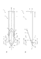
- FIG. 1 (a) is a top view on the front side
- FIG.1 (b) is a side view
- FIG.1 (c) is a top view on the back side
- FIG. 1 (d) is a perspective view.
- Fig.2 (a) is an enlarged view of the front-end
- FIG.2 (b) is an enlarged view of the front-end
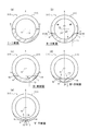
- 3A is a cross-sectional view taken along the line II in FIG. 2
- FIG. 3B is a cross-sectional view taken along the line II-II in FIG. 2
- FIG. 3C is a cross-sectional view taken along the line III-III in FIG. IV-IV sectional view in FIG. 2
- FIG. 3E is a VV sectional view in FIG. It is a figure which shows the puncture needle different from the puncture needle shown in FIG. 1
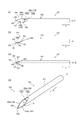
- Fig.4 (a) is a top view of a front side
- FIG.4 (b) is a side view
- FIG.4 (c) is a top view of a back side.
- FIG. 4D is a perspective view.
- Fig.5 (a) is an enlarged view of the front-end
- FIG.5 (b) is an enlarged view of the front-end
- FIGS. 7A and 7B are diagrams showing a modification of the puncture needle shown in FIG. 1, in which FIG. 7A is a front plan view, FIG. 7B is a side view, FIG. 7C is a back plan view, and FIG. (D) is a perspective view. It is a flowchart which shows the manufacturing method of the puncture needle as one Embodiment of this invention.
- FIG. 9A is a schematic diagram showing an outline of the blade surface forming process shown in FIG. 8, FIG. 9A is a schematic diagram of the first blade surface part forming process, FIG. 9B is a schematic diagram of the second blade surface part forming process, FIG. 9 (c) is a schematic diagram of the third blade surface portion forming step.
- FIG. 10A is a diagram showing a modification of the puncture needle shown in FIG. 1, FIG. 10A is a plan view on the front side, FIG. 10B is a side view, FIG. 10C is a plan view on the back side, FIG. (D) is a perspective view.
- FIG. 11A is a view of the puncture needle shown in FIG. 10 as viewed from the needle tip side, and FIG. 11B is a cross-sectional view taken along the line XII-XII in FIG.
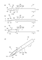
- FIG. 1 shows a puncture needle 1.
- FIG. 1 (a) is a plan view of the front side of the puncture needle 1
- FIG. 1 (b) is a side view of the puncture needle 1
- FIG. 1 (c) is a plan view of the back side of the puncture needle 1.
- FIG. FIG. 1 (d) is a perspective view of the puncture needle 1.
- the puncture needle 1 includes a main body portion 2 and a distal end portion 3, and defines a hollow portion 10 that communicates from the main body portion 2 to the distal end portion 3.
- the main body portion 2 is a hollow rod shape continuous with the tip portion 3, that is, a tubular tube.
- the main body 2 is a tubular body that is continuous with the distal end portion 3 and has a substantially circular cross-sectional outer shape.
- the “cross section” of the “cross sectional outline” referred to here means a transverse section orthogonal to the central axis O of the main body 2.
- the tip 3 is provided with a blade surface 4, and the blade surface 4 includes a first blade surface portion 5 as a front-side blade surface and a back-side blade surface.
- the puncture needle 1 of the present embodiment includes the blade surface 4 that has been subjected to backcut processing.
- the first blade surface portion 5 is configured by a plane that is inclined with respect to the central axis O of the main body portion 2 and extends to the needle tip 8.
- the 2nd blade surface part 6 and the 3rd blade surface part 7 are comprised by the curved surface, and the blade edge 23 which makes the needle tip 8 one end is formed in the back side of the 1st blade surface part 5 by the ridgeline which mutually cross
- the “needle tip” means the tip of the puncture needle 1 in the axial direction A of the central axis O of the main body 2 (hereinafter simply referred to as “central axial direction A”).
- the first blade surface portion 5 is a flat surface inclined at a predetermined angle such as 12 degrees or 18 degrees with respect to the central axis O, and the inner edge 13 thereof is an opening 11 that is one end of the hollow portion 10 on the distal end portion 3 side. Is partitioned.
- the outer edge 14 of the first blade surface portion 5 is formed by a blade edge 15 and a blade edge 16 having the needle tip 8 as one end, and a main body side outer edge portion 17. Details of the outer edge 14 of the first blade surface portion 5 will be described later.
- the second blade surface portion 6 and the third blade surface portion 7 have a symmetrical shape with respect to a virtual plane that passes through the needle tip 8 and includes the central axis O, and the second blade surface portion 6 and the third blade surface portion 7 are the same.
- a blade edge 23 having the needle tip 8 as one end is formed by a ridge line intersecting with each other.
- the blade edge 23 is linear, and this blade edge 23 also extends on the virtual plane.
- the virtual plane is a plane perpendicular to the first blade surface portion 5.
- center plane X a virtual plane that passes through the needle tip 8 and includes the central axis O
- the second blade surface portion 6 forms a blade edge 15 having the needle tip 8 as one end by a ridge line intersecting with the first blade surface portion 5.
- the blade edge 15 is a part of the outer edge 14 of the first blade surface portion 5, and extends from the needle tip 8 to the terminal point P on the outer edge 14.
- the 3rd blade surface part 7 forms the blade edge 16 which makes the needle tip 8 one end by the ridgeline which 1st blade surface part 5 cross
- This blade edge 16 is also a part of the outer edge 14 of the first blade surface portion 5, and extends from the needle tip 8 to the terminal point Q on the outer edge 14.
- a blade edge 23 formed by a ridge line where the second blade surface portion 6 and the third blade surface portion 7 intersect on the needle tip 8 side will be referred to as a “first blade edge 23”, and the first blade surface portion will be described.
- a blade edge 15 formed by a ridge line where 5 and the second blade surface part 6 intersect each other is referred to as a “second blade edge 15”, and a ridge line where the first blade surface part 5 and the third blade surface part 7 intersect each other.
- the formed blade edge 16 is referred to as “third blade edge 16”.
- the first blade edge 23, the second blade edge 15 and the third blade edge 16 work so as to cut the skin, thereby reducing the piercing resistance.
- the angle of the second blade surface portion 6 with respect to the center plane X in the cross section orthogonal to the center axis direction A varies depending on the position in the center axis direction A.
- the 2nd blade surface part 6 is comprised by the curved surface extended so that it might twist toward the needle-tip 8 side in the central axis direction A like a spiral surface, for example.
- the third blade surface portion 7 is also the same, and is formed of a curved surface extending so as to be twisted toward the needle tip 8 in the central axis direction A, for example, like a spiral surface.
- the 2nd blade surface part 6 and the 3rd blade surface part 7 have a symmetrical shape with respect to the center plane X as mentioned above, and the directions twisted toward the needle tip 8 side are opposite to each other. is there.
- the angle (gamma) with respect to the center plane X in the cross section orthogonal to the center axis direction A increases gradually toward the needle tip 8 side in the center axis direction A. It is composed of curved surfaces. If the 2nd blade surface part 6 is made into such a curved surface, compared with the structure which makes a 2nd blade surface part a plane, it is easy to ensure the length of the 2nd blade edge 15 longer. Moreover, if the 3rd blade surface part 7 is made into such a curved surface, compared with the structure which makes a 3rd blade surface part a plane, it is easy to ensure the length of the 3rd blade edge 16 longer.
- the thickness of the needle in the position in which the 2nd blade surface part 6 is formed is too thin. It is possible to suppress the decrease in the strength of the needle. Furthermore, since it can suppress that thickness becomes thin too much, inferior goods are hard to generate
- the puncture needle 1 of the present embodiment has a central plane in a cross section orthogonal to the central axis direction A as both the second blade surface portion 6 and the third blade surface portion 7 move toward the needle tip 8 side in the central axis direction A.
- the angle ⁇ with respect to X is composed of a curved surface that gradually increases, but either the second blade surface portion 6 or the third blade surface portion 7 is composed of such a curved surface, and the other has a flat surface or another surface shape. You may make it comprise with a curved surface.
- the angle with respect to the central plane X in the cross section orthogonal to the central axis direction A If it is configured by a curved surface in which ⁇ gradually increases, the total length of the second blade edge 15 and the third blade edge 16, that is, the first blade, as compared with the case where only one of them is configured by the above-described curved surface.
- the length from the terminal point P to the terminal point Q through the needle point 8 can be secured longer. Details of the lengths of the second blade edge 15 and the third blade edge 16 will be described later (see FIG. 3).
- the “tip portion” in the present application means a portion of the puncture needle in which the blade surface is formed in the central axis direction A
- the “main body portion” means the central axis direction A of the puncture needle.
- the distal end portion 3 in the present embodiment is the first blade surface portion 5, the second blade surface portion 6, and the third member in the central axis direction A among the tubular members as an integral hollow rod-shaped member constituting the puncture needle 1. This is a portion where the blade surface portion 7 is formed.
- the first blade surface portion 5, the second blade surface portion 6, and the third blade surface portion 7 in the central axial direction A among the integral cylindrical members constituting the puncture needle 1 are the same.
- a metal material such as stainless steel, aluminum or aluminum alloy, titanium or titanium alloy can be used.
- the main body 2 of the present embodiment is a tubular body in which the inner diameter of the inner peripheral surface and the outer diameter of the outer peripheral surface are uniform in the central axis direction A, and the end opposite to the tip 3 side in the central axis direction A
- the unit is connected to a medical instrument such as a syringe through a needle base or the like.
- the inner peripheral surface (the inner peripheral surface of the main body 2 and the inner peripheral surface of the distal end portion 3) of the cylindrical member constituting the entire puncture needle 1 defines the hollow portion 10, and the cylindrical member
- the inner diameter of the inner peripheral surface and the outer diameter of the outer peripheral surface are uniform in the central axis direction A, but are not limited to this configuration.
- the inner diameter of the inner peripheral surface of the cylindrical member and the outer diameter of the outer peripheral surface of the cylindrical member may be configured to gradually decrease toward the distal end portion 3 side in the central axis direction A.
- the outer diameter of the cylindrical member may be tapered so as to gradually decrease toward the tip 3 in the central axis direction A, and the inner diameter of the cylindrical member may be uniform in the central axis direction A. it can.
- the inner diameter of the cylindrical member constituting the puncture needle 1 such as providing a part where the inner diameter gradually decreases or gradually increases toward the distal end portion 3 side in the central axis direction A in a partial region in the central axis direction A and Various configurations can be adopted for the outer diameter according to the use of the puncture needle 1 and the like.
- FIGS. 1 (a) and 1 (b) are enlarged views of the distal end portion 3 shown in FIGS. 1 (a) and 1 (b), respectively.
- 3 (a), (b), (c), (d) and (e) are respectively a II sectional view, a II-II sectional view, a III-III sectional view, an IV-IV sectional view and a VV in FIG. It is sectional drawing.
- the first blade surface portion 5 is a flat surface that is inclined with respect to the central axis direction A.
- one end of the first blade surface portion 5 is a needle tip. 8 and the other end is continuous with the outer peripheral surface of the main body 2.
- the inclination angle of the first blade surface portion 5 with respect to the central axis direction A is larger than the inclination angle of the outer wall of the main body portion 2 with respect to the central axis direction A in the cross section orthogonal to the first blade surface portion 5.
- the outer diameter of the cylindrical member constituting the puncture needle 1 is uniform in the central axis direction A, and the outer wall of the cylindrical member is the central axis in a cross-sectional view orthogonal to the first blade surface portion 5. It extends in direction A. Therefore, if the first blade surface portion 5 is inclined with respect to the central axis direction A, the inclination angle of the first blade surface portion 5 is larger than the inclination angle of the outer wall of the main body portion 2.
- the first blade surface portion 5 has the first blade In a cross section orthogonal to the surface portion 5, the surface portion 5 is not only inclined with respect to the central axis direction A but also inclined with respect to the outer wall of the main body portion 2.
- the outer edge 14 of the first blade surface portion 5 is at one end of the second blade edge 15, the third blade edge 16, and the second blade edge 15 on the main body portion 2 side.
- a main body side outer edge portion 17 having a convex curve shape that connects a terminal point P and a terminal point Q that is one end of the third blade edge 16 on the main body portion 2 side.
- the 2nd blade edge 15 and the 3rd blade edge 16 are formed by the curve, and the 2nd blade edge 15 and the main-body part side outer edge part 17 are connected by the continuous curve without passing through the vertex.
- the second blade edge 15 is continuous with the main body portion side outer edge portion 17 without forming a vertex at the position of the terminal point P which is also a connection point with the main body portion side outer edge portion 17.
- the third blade edge 16 and the main body portion side outer edge portion 17 are also connected by a continuous curve without passing through the apex.
- the third blade edge 16 is connected to the main body portion side outer edge portion 17.
- it is continuous with the main body side outer edge portion 17 without forming a vertex.
- the apex is not formed at the position of the terminal point P or the terminal point Q as in the present embodiment, but the piercing resistance is not greatly increased at the position of the terminal point P or the terminal point Q. It is good also as a structure in which a vertex is formed.
- the second blade surface portion 6 and the third blade surface portion 7 are curved surfaces in which the angle ⁇ with respect to the center plane X in the cross section orthogonal to the center axis direction A gradually increases as going toward the needle tip 8 in the center axis direction A. It consists of Hereinafter, with reference to FIG. 3, the detail of the shape of the 2nd blade surface part 6 and the 3rd blade surface part 7 is demonstrated.
- FIG. 3A is a sectional view taken along the line II in FIG. 2, that is, the position where the first blade surface portion 5 is formed in the central axis direction A, and the second blade surface portion 6 and the third blade surface portion 7 are not formed.
- a cross section perpendicular to the central axis direction A at the position is shown.
- the angle ⁇ with respect to the center plane X of the first blade surface portion 5 in the II cross section of FIG. 2 is 90 degrees.
- the first blade surface portion 5 extends linearly in a direction orthogonal to the central plane X.
- the first blade surface portion 5 is configured by a plane inclined with respect to the central axis O, and therefore in FIGS. 3B to 3E referred to below, FIG. ),
- the angle ⁇ with respect to the central plane X of the first blade surface portion 5 is constant at 90 degrees.
- FIG. 3B shows the II-II cross section of FIG. 2, that is, a cross section passing through the terminal point P of the second blade edge 15 and the terminal point Q of the third blade edge 16 and orthogonal to the central axis direction A.
- FIG. 3B is a cross section orthogonal to the central axis direction A at the ends of the second blade surface portion 6 and the third blade surface portion 7 on the main body portion 2 side.
- the second blade surface portion 6 and the third blade surface portion 7 in the II-II cross section of FIG. 2 are inclined with respect to the central plane X at a predetermined acute angle ⁇ 1.
- FIG. 3C is a cross-sectional view taken along the line III-III of FIG. 2, that is, a position closer to the needle tip 8 in the central axis direction A than the cross section shown in FIG. 3B, and there is an opening 11 in the central axis direction A.
- a cross section perpendicular to the central axis direction A at the position is shown.
- FIG. 3C shows a position where the first blade edge 23 is not formed in the central axis direction A and a position where the second blade edge 15 and the third blade edge 16 are formed. It is a cross section orthogonal to the central axis direction A.
- each of the second blade surface portion 6 and the third blade surface portion 7 in the III-III cross section of FIG. 2 is inclined with respect to the center plane X at a predetermined angle ⁇ 2.
- the angle ⁇ 2 with respect to the central plane X in the cross section shown in FIG. 3C is an acute angle larger than the angle ⁇ 1 in the cross section shown in FIG.
- 3D is a cross-sectional view taken along the line IV-IV of FIG. 2, that is, the position closer to the needle tip 8 in the central axis direction A than the cross section shown in FIG. 3C, and there is an opening 11 in the central axis direction A.
- a cross section perpendicular to the central axis direction A at the position is shown.
- each of the second blade surface portion 6 and the third blade surface portion 7 in the IV-IV cross section of FIG. 2 is inclined at a predetermined angle ⁇ 3 with respect to the center plane X.
- the angle ⁇ 3 is an acute angle larger than the angle ⁇ 1 in the cross section shown in FIG. 3B and larger than the angle ⁇ 2 in the cross section shown in FIG.
- FIG. 3E shows the VV cross section of FIG. 2, that is, the central axis direction A at the position where the first blade edge 23, the second blade edge 15 and the third blade edge 16 are formed in the central axis direction A.
- the cross section orthogonal to is shown.
- each of the second blade surface portion 6 and the third blade surface portion 7 in the VV cross section of FIG. 2 is inclined at a predetermined angle ⁇ 4 with respect to the center plane X, and this angle ⁇ 4. Is larger than the angle ⁇ 1 in the cross section shown in FIG. 3 (b), larger than the angle ⁇ 2 in the cross section shown in FIG. 3 (c), and larger than the angle ⁇ 3 in the cross section shown in FIG. 3 (d). It is an acute angle.
- each of the second blade surface portion 6 and the third blade surface portion 7 is a straight line in a cross-sectional view orthogonal to the central axis direction A, and each of the second blade surface portion 6 and the third blade surface portion 7 in the present embodiment.
- the angle ⁇ with respect to the central plane X in the cross section orthogonal to the central axis direction A gradually increases toward the needle tip 8 side (closer to the needle tip 8) in the central axis direction A.
- 3B to 3E show the angles ⁇ 1 to ⁇ 4 with respect to the center plane X of the third blade surface portion 7, respectively, but the angle of the second blade surface portion 6 with respect to the center plane X is also the third blade surface 6. This is the same as the angles ⁇ 1 to ⁇ 4 of the surface portion 7.
- FIGS. 3B to 3E are used for illustrative purposes to show the magnitude relationship between the angles ⁇ 1, ⁇ 2, ⁇ 3, and ⁇ 4, and are limited to these four cross sections.
- the magnitude relationship of the angle ⁇ is not established.
- the third blade surface portion 7 of the present embodiment is a straight line in a cross-sectional view orthogonal to the central axis direction A, but is not limited to this configuration.
- the third blade surface portion may have a configuration in which a cross-sectional view orthogonal to the central axis direction A is an arcuate curve, or a configuration in which the cross-sectional view is a straight line and an arcuate curve continuous to the straight line. it can. The same applies to the second blade surface portion.
- the angle ⁇ of the second blade surface portion and the third blade surface portion is set to a straight line passing through the inner edge and the outer edge of each of the second blade surface portion and the third blade surface portion in a cross section orthogonal to the central axis direction A.
- the first blade edge 23 is formed by a ridge line where the second blade surface portion 6 and the third blade surface portion 7 intersect. Further, as described above, the first blade edge 23 of the present embodiment extends on the center plane X, and the needle tip 8 that is one end of the first blade edge 23 is also positioned on the center plane X. To do. That is, the puncture needle 1 in this embodiment is a hollow needle having a symmetric configuration with respect to the central plane X.
- the first blade edge 23 functions as a cutting blade that tears the skin when the puncture needle 1 is punctured into a human body, puncture resistance in the vicinity of the needle tip 8 at the time of puncture can be reduced.
- the circumferential extension range of the second blade edge 15 represented by the angle ⁇ 1 can be increased (see FIG. 3B).
- the center angle ⁇ 1 can be 50 degrees or more, and can be 70 degrees or more.
- the second blade edge 15 can be secured longer, so that the skin is removed by the second blade edge 15 when the puncture needle 1 is punctured.
- the cutting width W1 (see FIG. 3B) that can be cut can be increased. That is, the 2nd blade surface part 6 comprised by the curved surface mentioned above can enlarge the cutting width W1 by the 2nd blade edge 15 compared with the 2nd blade surface part comprised by the plane. Therefore, after the second blade edge 15 passes through the skin, the outer needle that is attached to the outer surface of the main body 2 of the puncture needle 1 or around the puncture needle 1 using the puncture needle 1 as an inner needle and punctured with the puncture needle 1.
- the cutting width W1 can be increased, when the puncture needle 1 is used as an indwelling needle, for example, the catheter covering the puncture needle 1 easily enters the skin and blood vessels, and prevents the catheter from dripping at the time of puncture. be able to.
- the third blade surface portion 7 is the same as the second blade surface portion 6 described above. Specifically, if the third blade surface portion 7 is configured by a curved surface in which the angle ⁇ with respect to the center plane X in the cross section orthogonal to the center axis direction A gradually increases toward the needle tip 8 side in the center axis direction A, the third The length of the blade edge of the third blade edge 16 can be ensured longer than in the case where the blade surface portion is configured as a flat surface. In other words, if the third blade surface portion 7 is configured with such a curved surface, the center from the needle tip 8 to the end point Q centered on the central axis O when the puncture needle 1 is viewed from the needle tip 8 side.
- the circumferential extension range of the third blade edge 16 represented by the angle ⁇ 2 can be increased (see FIG. 3B).
- the center angle ⁇ 2 can be 50 degrees or more, and can be 70 degrees or more.
- the third blade edge 16 can be secured longer, so that the skin is removed by the third blade edge 16 when the puncture needle 1 is punctured.
- the cutting width W2 (see FIG. 3B) that can be cut can be increased. That is, the third blade surface portion 7 configured with the curved surface described above can increase the cutting width W2 by the third blade edge 16 as compared with the third blade surface portion configured with a flat surface. Therefore, after the third blade edge 16 passes through the skin, the outer needle that is attached to the outer surface of the main body 2 of the puncture needle 1 or around the puncture needle 1 using the puncture needle 1 as an inner needle and punctured together with the puncture needle 1.
- the outer surface Due to the outer surface, it is possible to suppress the amount of spreading that the skin cut is forcibly spread. Therefore, it is possible to reduce the pain felt by the patient at the time of puncture. Further, if the cutting width W2 can be increased, when the puncture needle 1 is used as an indwelling needle, for example, the catheter covering the puncture needle 1 can easily enter the skin and blood vessels, and the catheter can be prevented from dripping at the time of puncture. be able to.
- both the 2nd blade surface part 6 and the 3rd blade surface part 7 are comprised by the curved surface mentioned above like this embodiment, the cutting width W1 by the 2nd blade edge 15 and the cutting width W2 by the 3rd blade edge 16 will be mentioned. Is preferable because only one of them can be made larger than that of the curved surface.
- the puncture needle 1 of the present embodiment is a hollow needle that divides the hollow portion 10 inside, but is not limited to this configuration, and may be a solid needle that does not have a hollow portion.
- FIG. 7 is a view showing a puncture needle 1 ′ as a modification of the puncture needle 1 of the present embodiment, FIG. 7 (a) is a plan view of the front side, FIG. 7 (b) is a side view, and FIG. c) is a plan view of the back side, and FIG. 7 (d) is a perspective view.
- the puncture needle 1 ′ is a solid needle that does not define a hollow portion inside, and other configurations are the same as those of the puncture needle 1 of the present embodiment. Therefore, in FIG.
- symbol is attached
- the puncture needle 1 ′ shown in FIG. 7 does not define a hollow portion inside, the first blade surface portion 5 ′ of the blade surface 4 ′ is inclined at a predetermined angle with respect to the central axis O of the main body portion 2 ′. , It is constituted by a uniform plane having no opening at the center. Note that the main body 2 'of the puncture needle 1 shown in FIG. 7 has a solid bar shape.
- the main body 2 of the puncture needle 1 of the present embodiment has a substantially circular cross-sectional outer shape, but it may be a hollow or solid bar-shaped main body. It is not limited.
- any cross section may be a main body having a substantially elliptical cross-sectional shape, and any cross-section may be a main body having a cross-sectional shape having a substantially circular shape or a substantially elliptical shape. Further, it may be a main body part having a part whose cross-sectional outer shape is substantially circular or substantially elliptical.
- the shape other than the circular shape may be any shape as long as it has a flat cross-sectional outer shape defined by the major axis and the minor axis, and is not limited to the above-described elliptical shape.
- FIG. 10 is a view showing a puncture needle 151 including a main body 152 whose outer shape of an arbitrary cross section is substantially circular or elliptical
- FIG. 10A is a plan view of the front side of the puncture needle 151.
- FIG. 10B is a side view of the puncture needle 151
- FIG. 10C is a plan view of the back side of the puncture needle 151
- FIG. 10D is a perspective view of the puncture needle 151.
- the puncture needle 151 shown in FIG. 10 includes a main body portion 152 and a distal end portion 153, and defines a hollow portion 160 that communicates from the main body portion 152 to the distal end portion 153.
- the main body 152 is a hollow rod that is continuous with the tip 153, that is, a tubular tube. More specifically, the main body portion 152 is positioned on the base end side of the main body front end portion 152a having a substantially elliptical cross-sectional shape that is continuous with the front end portion 153, and has a substantially circular cross-sectional outer shape.
- a main body trunk portion 152b, and a connecting portion 152c that is located between the main body front end portion 152a and the main body trunk portion 152b and connects the main body front end portion 152a and the main body trunk portion 152b.
- the main body distal end portion 152a has a substantially elliptical cross-sectional outer shape in which the width S1 in the plan view of FIGS. 10A and 10C is the major axis and the width S2 in the side view of FIG. 10B is the minor axis.
- the width S1 as the major axis of the main body tip portion 152a is larger than the outer diameter of the main body trunk portion 152b, and is the width as the minor axis of the main body tip portion 152a.
- S2 is smaller than the outer diameter of the main body trunk 152b.
- the central axis of the main body distal end portion 152a and the central axis of the main body trunk portion 152b substantially coincide with each other, and the central axis O of the main body portion 152 is substantially a straight line. Therefore, the connecting portion 152c gradually increases toward the distal end portion 153 side in the central axis direction A in a plan view (see FIGS. 10A and 10C) on the front side and the back side, In the side view (see FIG. 10B), it has a tapered shape that gradually decreases in the central axis direction A toward the front end 153 side.
- the center plane X including the center axis O and the needle tip 158 is a plane including a minor axis in a cross section orthogonal to the center axis direction A of the main body tip portion 152a.
- the front end portion 153 is continuous with the main body front end portion 152a having a substantially elliptical cross section.
- the distal end portion 153 includes a blade surface 154.
- the blade surface 154 includes a first blade surface portion 155 as a front blade surface, and a second blade surface portion 156 and a third blade surface portion 157 as a back blade surface. I have.
- the first blade surface portion 155 is configured by a flat surface that is inclined with respect to the central axis O of the main body portion 152 and extends to the needle tip 158.
- the 2nd blade surface part 156 and the 3rd blade surface part 157 are comprised by the curved surface, and the blade edge 173 which makes the needle tip 158 one end is formed in the back side of the 1st blade surface part 155 by the ridgeline which mutually cross
- the 2nd blade surface part 156 and the 3rd blade surface part 157 are arrange
- the shape of the first blade surface portion 155 shown in FIG. 10 is a plane inclined at a predetermined angle such as 12 degrees or 18 degrees with respect to the central axis O, like the shape of the first blade surface portion 5 of the puncture needle 1 described above. Therefore, the description is omitted here.
- the shapes of the second blade surface portion 156 and the third blade surface portion 157 shown in FIG. 10 are similar to the shapes of the second blade surface portion 6 and the third blade surface portion 7 of the puncture needle 1 described above, in the center axis direction A. It is composed of a curved surface in which the angle ⁇ with respect to the central plane X in the cross section orthogonal to the central axis direction A gradually increases toward the 158 side, and the description thereof is omitted here.
- the puncture needle 151 shown in FIG. 10 is different from the puncture needle 1 described above in that the main body 152 and the distal end 153 have different cross-sectional outlines perpendicular to the central axis direction A, and the puncture needle 151.
- the maximum thickness of the distal end portion 153 in the side view is thinner than the maximum thickness of the distal end portion 3 in the side view of the puncture needle 1 described above (see FIG. 1B).
- the short axis in the cross section orthogonal to the central axis direction A of the main body distal end portion 152a is included in the central plane X. With such a configuration, it is easier to realize a puncture needle 151 having a shorter blade surface length M than the puncture needle 1 described above.
- FIG. 11A is a view of the puncture needle 151 shown in FIG. 10 as viewed from the needle tip 158 side.
- “R1” indicated by the alternate long and short dash line is a long axis
- “R2” is a short axis.
- the needle tip 158 has an outer periphery of the main body trunk portion 152b when viewed in the central axis direction A (for the sake of convenience, the portion that cannot be seen from the viewpoint of FIG. 11 (a). Is inward of the broken line BL).
- the puncture needle 151 has a distal end portion 153 having a flat cross-sectional outer shape including the needle tip, and a main body having a flat cross-sectional outer shape continuous with the distal end portion 153 and defined by the major axis R1 and the minor axis R2.
- the distal end portion 153 includes a blade surface 154, and the blade surface 154 Is inclined with respect to the central axis O of the main body trunk portion 152b and extends to the needle tip 158, and the second blade surface portion 156 and the third blade surface portion 156 formed on the back side of the first blade surface portion 155.
- the needle tip 158 is located on the inner side of the outer periphery of the main body trunk 152b when viewed in the central axis direction A.
- the length in the central axis direction A of the first blade surface portion 155 is as viewed in the central axis direction A.
- the inclination angle with respect to the central axis direction A is equal to the length in the central axis direction A of the first blade surface portion in the comparative configuration in which the position of the needle tip is located on the outer periphery of the main body trunk portion 152b or outside the outer periphery. It can be made smaller than the inclination angle with respect to the central axis direction A of the first blade surface portion in the comparative configuration. Therefore, it is easy to realize the first blade surface portion 155 that can reduce the pressing force pressed toward the back side from the body tissue during puncturing. That is, it becomes easy to realize the puncture needle 151 that improves the straightness.
- the blade edge angle ⁇ can be further reduced while keeping the length of the first blade surface portion 155 in the central axis direction A the same. Therefore, it is easy to realize a puncture needle 151 that has a thin blade edge and can reduce piercing resistance at the blade edge.
- the blade edge angle ⁇ is such that the blade edge 173 and the front surface opposite to the blade edge 173 intersect at the needle tip 158 in a side view of the puncture needle 151 (see FIG. 10B). Means an angle.
- the needle tip 158 when viewed in the central axis direction A (see FIG. 11A), the needle tip 158 is located near the position of one end in the short axis direction (the direction parallel to the short axis R2 in FIG. 11A). Although it is formed, it suffices if it is located inside the outer periphery of the main body trunk portion 152b when viewed in the central axis direction A (see FIG. 11A). It is not limited to the position. However, the needle tip 158 has the position of one end in the short axis direction, or the vicinity of the position of one end in the short axis direction as shown in FIGS. It is preferably described as “position on one end side in the minor axis direction”).
- the second blade surface portion 156 and the third blade surface portion in the tip portion 153 having a flat cross-sectional outer shape when viewed in the central axis direction A as in the elliptical shape shown in FIG. 157 can be formed at a position with a large radius of curvature.
- the length of the blade edge comprised by each outer edge of the 2nd blade surface part 156 and the 3rd blade surface part 157 can be ensured long, As a result, crossing angle (tau) (refer “tau12" of Drawing 11 (b)) It becomes easy to ensure the length of the cutting edge which becomes a predetermined angle (for example, 60 degrees) or less.
- the needle tip 158 is in the long axis direction (the direction parallel to the long axis R1 in FIG. 11A).
- the angle ⁇ is inclined to the acute angle of the second blade surface portion 156 and the third blade surface portion 157 with respect to the center plane X including the needle tip 158. In the angle range of larger angles, a configuration that changes according to the position in the central axis direction A can be realized.
- the blade surface portion 157 can be a curved surface that is further along the long axis R1. Therefore, among the blade edges formed by the outer edges of the second blade surface portion 156 and the third blade surface portion 157, the intersection angle ⁇ (see “ ⁇ 12” in FIG. 11B) is a predetermined angle (for example, 60 degrees) or less. It becomes easy to ensure the length of the part of the cutting edge which becomes longer.
- the blade edge formed by the outer edges of the second blade surface portion 156 and the third blade surface portion 157 is formed by a ridge line where each of the second blade surface portion 156 and the third blade surface portion 157 and the first blade surface portion 155 intersect. It is a part to be done.
- the cutting edge referred to here has a predetermined crossing angle ⁇ (refer to “ ⁇ 12” in FIG. 11B) among the edges formed by the outer edges of the second blade surface portion 156 and the third blade surface portion 157. It means a portion extending from the needle tip 158 to a predetermined length that is an angle (for example, 60 degrees) or less.
- the crossing angle ⁇ means an angle formed between each of the second blade surface portion 156 and the third blade surface portion 157 and the first blade surface portion 155 in a cross section orthogonal to the central axis direction A.
- the cutting blade described here cuts the skin together with the blade edge 173 at the time of puncturing. Therefore, the outer edges of the second blade surface portion 156 and the third blade surface portion 157 are secured at the time of puncturing by ensuring a long cutting edge at the blade edge constituted by the outer edges of the second blade surface portion 156 and the third blade surface portion 157, respectively. The pain felt by the patient by passing can be reduced.
- the blade edge constituted by the outer edge of at least one of the second blade surface portion 156 and the third blade surface portion 157 is when the tip portion 153 is viewed in the central axis direction A (see FIG. 11A). Further, it is preferable that the main body trunk portion 152b extends to the outside of the outer periphery. In the example shown in FIG. 11A, both blade edges formed by the outer edges of both the second blade surface portion 156 and the third blade surface portion 157 extend to the outside of the outer periphery of the main body trunk portion 152b.
- the distal end portion 153 of the puncture needle 151 has a flat cross-sectional outer shape, and the needle tip 158 is on one end side in the minor axis direction (the direction parallel to the minor axis R2 in FIG. 11A). Formed in position. Therefore, as described above, in the blade edge constituted by the outer edges of the second blade surface portion 156 and the third blade surface portion 157, the length of the cutting blade whose crossing angle ⁇ is equal to or less than a predetermined angle (for example, 60 degrees) is increased. Easy to secure. In addition, as shown in FIG.
- the main body when the blade edge constituted by the outer edges of the second blade surface portion 156 and the third blade surface portion 157 is viewed from the front end portion 153 in the central axis direction A, the main body If the configuration extends to the outside of the outer periphery of the body portion 152b, the long-axis direction extends from the needle tip 158 to the outside of the outer periphery of the body body portion 152b when the tip portion 153 is viewed in the central axis direction A. It is easy to realize a cutting edge that is long in the direction parallel to the long axis R1 in FIG. If such a long cutting edge can be realized, the pain felt by the patient by passing the outer edges of the second blade surface portion 156 and the third blade surface portion 157 during puncture can be further reduced.
- FIG.11 (b) is XII-XII sectional drawing of Fig.10 (a).
- the blade edge constituted by the outer edges of the second blade surface portion 156 and the third blade surface portion 157 forms a cutting edge whose crossing angle ⁇ 12 is a predetermined angle (for example, 60 degrees) or less.
- the blade edge constituted by the outer edges of the second blade surface portion 156 and the third blade surface portion 157 extends from the needle tip 158 to the outside of the outer periphery of the main body barrel portion 152b when the tip portion 153 is viewed in the central axis direction A.
- a long cutting edge is formed in the long axis direction (direction parallel to the long axis R1 in FIG. 11A).
- the needle tip 158 when the outer edge of at least one of the second blade surface portion 156 and the third blade surface portion 157 is viewed from the needle tip 158 when the tip portion 153 is viewed in the central axis direction A, It is preferable to have a configuration that reaches the position where the width of the tip 153 is maximum in the long axis direction. Furthermore, as in the example shown in FIG. 11A, when the outer edges of both the second blade surface portion 156 and the third blade surface portion 157 are viewed from the tip portion 153 in the central axis direction A, the needle tip 158 It is particularly preferable to have a configuration in which the width of the tip 153 reaches the maximum in the long axis direction.
- the cutting edge can be formed over the entire width of the distal end portion 153 in the major axis direction. If a cutting edge with a crossing angle ⁇ of a predetermined angle (for example, 60 degrees) or less can be formed over the entire width of the distal end portion 153 in the major axis direction, the pain felt by the patient by passing the distal end portion 153 during puncture Can be further reduced.
- a crossing angle ⁇ of a predetermined angle for example, 60 degrees
- FIG. 4 shows the puncture needle 101.
- 4A is a plan view of the front side of the puncture needle 101
- FIG. 4B is a side view of the puncture needle 101
- FIG. 4C is a plan view of the back side of the puncture needle 101.
- FIG. FIG. 4D is a perspective view of the puncture needle 101.
- 5 (a) and 5 (b) are enlarged views of the tip portion 103 shown in FIGS. 4 (a) and 4 (b), respectively.
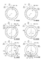
- 6 (a), (b), (c), (d), (e), and (f) are respectively a VI-VI sectional view, a VII-VII sectional view, a VIII-VIII sectional view, and an IX in FIG. -IX sectional drawing, XX sectional drawing, XI-XI sectional drawing.
- the puncture needle 101 includes a main body portion 102 and a distal end portion 103, and defines a hollow portion 110 penetrating from the main body portion 102 to the distal end portion 103.
- the tip portion 103 includes a blade surface 104.
- the blade surface 104 includes a first blade surface portion 105 as a front-side blade surface, and a second blade surface portion 106 and a third blade surface portion 107 as back-side blade surfaces formed on the back side of the front-side blade surface.
- the puncture needle 101 includes a blade surface 104 that has been subjected to backcut processing.
- the configuration of the main body 102 is the same as that of the main body 2 of the puncture needle 1 described above.
- the first blade surface portion 105 includes a first bevel surface 105a, a second bevel surface 105b, and a third bevel surface 105c that are formed of curved surfaces.
- the first bevel surface 105a and the second bevel surface 105b form a blade edge 109 having the needle tip 108 as one end by a ridge line intersecting each other.
- each of the first bevel surface 105a and the second bevel surface 105b is continuous with the third bevel surface 105c on the main body 102 side in the central axis direction A.
- the first bevel surface 105 a and the second bevel surface 105 b define an opening 111 that is one end of the hollow portion 110 on the distal end portion 103 side.
- the third bevel surface 105c is continuous with the outer peripheral surface of the main body 102 on the main body 102 side in the central axis direction A, and is continuous with the first and second bevel surfaces 105a and 105b on the needle tip 108 side in the central axis direction A. is doing.
- the angle of the second bevel surface 105b in the cross section perpendicular to the central axis direction A varies depending on the position in the central axis direction A. .
- the second bevel surface 105b and the third bevel surface 105c are continuous in the central axis direction A, only the outer edge of the second bevel surface 105b is visible.
- the second bevel surface 105b can be visually recognized at the position where the blade edge 109 is formed in the central axis direction A.
- the second bevel surface 105b is configured by a curved surface that extends to twist toward the needle tip 108 from a position continuous with the third bevel surface 105c in the central axis direction A, such as a spiral surface.
- the first bevel surface 105a is also configured by a curved surface extending so as to twist toward the needle tip 108 from a position continuous with the third bevel surface 105c in the central axis direction A in the same manner as the second bevel surface 105b.
- the direction in which the first bevel surface 105a and the second bevel surface 105b are twisted toward the needle tip 108 is opposite.
- the first bevel surface 105a and the second bevel surface 105b are set to one imaginary plane including the central axis O of the main body 102, the first bevel surface 105a and the second bevel surface 105b become centered toward the needle tip 108 side in the central axis direction A. It is composed of a curved surface in which an angle ⁇ with respect to the one virtual plane in a cross section orthogonal to the axial direction A gradually decreases. That is, the puncture needle 101 is a puncture needle that can define such one virtual plane.
- the puncture needle 101 has one plane that can be defined as the “virtual plane” described above.
- the above-mentioned “virtual plane” can be set to the center plane X including the center axis O and the needle tip 108, and the first bevel surface 105a and the second bevel surface 105b are both In the central axis direction A, it is composed of a curved surface in which the angle ⁇ with respect to the central plane X in the cross section orthogonal to the central axis direction A gradually decreases toward the needle tip 108 side.
- the center plane X is a plane including not only the needle tip 108 but also the blade edge 109 and a blade edge 123 described later.
- first bevel surface 105a and the second bevel surface 105b move toward the needle tip 108 side in the central axis direction A, the angle ⁇ with respect to the central plane X in the cross section orthogonal to the central axial direction A gradually decreases.
- one of the first bevel surface 105a and the second bevel surface 105b is configured by such a curved surface, and the other is configured by a curved surface having a flat surface or another surface shape. May be.
- both the first bevel surface 105a and the second bevel surface 105b are curved surfaces in which the angle ⁇ with respect to the central plane X in the cross section orthogonal to the central axial direction A gradually decreases as the direction toward the needle tip 108 in the central axial direction A is increased. If configured, it is possible to easily realize the first blade surface portion 105 in which a ridge line (junction) that can be puncture resistance is not formed between the first and second bevel surfaces 105a and 105b and the third bevel surface 105c. it can.
- the third bevel surface 105c is formed of a convex curved surface that is continuous with the first bevel surface 105a and the second bevel surface 105b. Specifically, the third bevel surface 105c is a convex curved surface that is inclined so that the side view in FIG. 5B approaches the central axis O as it approaches the needle tip 108 in the central axis direction A.
- the angle ⁇ with respect to the central plane X in the cross section orthogonal to the direction A is substantially constant regardless of the position in the central axis direction A.
- the third bevel surface 105 c is a tip side portion 140 a that is continuous with the first bevel surface 105 a and the second bevel surface 105 b on the needle tip 108 side in the central axis direction A.
- a proximal end side portion 140b that is continuous with the main body portion 102 side of the distal end side portion 140a in the central axis direction A.
- the distal end side portion 140a and the proximal end side portion 140b are configured by convex curved surfaces having different curvatures in a side view (see FIGS. 4B and 5B).
- both of the distal end side portion 140a and the proximal end side portion 140b are configured by curved surfaces in which the angle ⁇ with respect to the central plane X in the cross section orthogonal to the central axial direction A is substantially constant regardless of the position in the central axial direction A. Yes. And between the 1st bevel surface 105a and the 2nd bevel surface 105b, and the front end side part 140a, and between the front end side part 140a and the base end side part 140b, it continues smoothly so that a ridgeline may not be formed. .
- the puncture needle 101 has a distal end side portion 140a and a proximal end side portion 140b having different curvatures in a side view (see FIGS. 4B and 5B), and continues in the central axis direction A.
- a ridge line serving as a piercing resistance is not formed between the first and second bevel surfaces 105a and 105b and the third bevel surface 105c. That is, the distal end side portion 140a of the third bevel surface 105c is a connection curved surface for smoothly connecting the first and second bevel surfaces 105a and 105b and the proximal end side portion 140b of the third bevel surface 105c.
- the curvature in the side view is configured to be larger than the curvature of the base end side portion 140b.
- the distal end side portion 140a includes a first connection curved surface 130a positioned between the first bevel surface 105a and the proximal end side portion 140b in the central axis direction A.
- the second connecting curved surface 130b is located between the second bevel surface 105b and the base end side portion 140b in the central axis direction A.
- the first bevel surface 105a is smoothly connected to the proximal end side portion 140b via the first connection curved surface 130a of the distal end side portion 140a
- the second bevel surface 105b is connected to the first bevel surface 105a of the distal end side portion 140a.
- the base end side portion 140b is smoothly connected via the two connection curved surface 130b. 4A and 4D, lines drawn between the first bevel surface 105a and the second bevel surface 105b and the distal end side portion 140a, and the distal end side portion 140a and the proximal end side.
- the line drawn between the portion 140b simply means a boundary line.
- both the distal end side portion 140a and the proximal end side portion 140b of the third bevel surface 105c are inclined so as to gradually approach the central axis O toward the needle tip 108 side in the central axial direction A.
- the inclination angle of 140a and the base end side portion 140b with respect to the central axis direction A is larger than the inclination angle of the outer wall of the main body 102 with respect to the central axis direction A in the cross section including the entire central axis O.
- the “inclination angle with respect to the central axis direction of the distal end side portion” here refers to the third bevel surface including the entire central axis. In the cross-section passing through the upper tip side portion, it means an angle formed by a tangent line at an arbitrary point on the tip side portion of the third bevel surface with the central axis. Further, the “inclination angle of the base end side portion with respect to the central axis direction” is an arbitrary value on the base end side portion of the third bevel surface in a cross section including the entire central axis and passing through the base end side portion on the third bevel surface. The tangent at this point means the angle formed with the central axis.
- the outer diameter of the cylindrical member constituting the puncture needle 101 is uniform regardless of the position in the central axis direction A, and the outer wall of the cylindrical member is the center when viewed in a cross section including the entire central axis O. It extends in the axial direction A. Therefore, as long as the distal end side portion 140a and the proximal end side portion 140b of the third bevel surface 105c are inclined with respect to the central axis direction A, the inclination angle of the distal end side portion 140a and the proximal end side portion 140b is the main body. It becomes larger than the inclination angle of the outer wall of the portion 102.
- the distal end side portion 140a of the third bevel surface 105c is configured not only to be inclined with respect to the central axis direction A but also to be inclined with respect to the outer wall of the main body 102 in a cross section including the entire central axis O.
- the 2nd blade surface part 106 and the 3rd blade surface part 107 are center axis line as it goes to the needle tip 108 side in the central axis direction A like the 2nd blade surface part 6 and the 3rd blade surface part 7 of the puncture needle 1 mentioned above. It is composed of a curved surface in which an angle ⁇ with respect to the central plane X in a cross section orthogonal to the direction A gradually increases.
- the second blade surface portion 106 is formed on the back side of the first bevel surface 105a, and the third blade surface portion 107 is formed on the back side of the second bevel surface 105b. Further, the second blade surface portion 106 and the third blade surface portion 107 form a blade edge 123 having the needle tip 108 as one end by a ridge line intersecting with each other on the needle tip 108 side in the central axis direction A.
- first bevel surface 105a and the second blade surface portion 106 form a blade edge 124 having the needle tip 108 as one end by a ridge line intersecting each other. More specifically, the blade edge 124 is configured by a ridge formed by the outer edge of the first bevel surface 105 a and the outer edge of the second blade surface portion 106.
- the second bevel surface 105b and the third blade surface portion 107 form a blade edge 125 having the needle tip 108 as one end by a ridge line intersecting each other. More specifically, the blade edge 125 is configured by a ridge formed by the outer edge of the second bevel surface 105 b and the outer edge of the third blade surface portion 107.
- a blade edge 123 formed by a ridge line where the second blade surface portion 106 and the third blade surface portion 107 intersect with each other will be referred to as a “first blade edge 123”, and the first bevel surface 105a and the first blade edge portion 105a.
- a blade edge 124 formed by a ridge line intersecting the two blade surface portions 106 is referred to as a “second blade edge 124”, and a blade edge formed by a ridge line intersecting the second bevel surface 105 b and the third blade surface portion 107.
- blade edge 125 is referred to as a “third blade edge 125”, and a blade edge 109 formed by a ridge line where the first bevel surface 105a and the second bevel surface 105b intersect is referred to as a “fourth blade edge 109”.
- the puncture needle 101 includes the first blade surface portion 105 as the front-side blade surface, and the second blade surface portion 106 and the third blade surface portion 107 as the back-side blade surface.
- the tip 108 can be sharpened, and the piercing resistance in the vicinity of the needle tip 108 can be reduced.
- the 2nd blade surface part 106 and the 3rd blade surface part 107 are comprised by the curved surface from which the angle (gamma) with respect to the center plane X in the cross section orthogonal to the center axis direction A increases gradually toward the needle tip 108 side in the center axis direction A.
- the vicinity of the needle tip 108 can be sharpened, and piercing resistance can occur between the second blade surface portion 106 and the third blade surface portion 107 and the outer peripheral surface of the cylindrical member constituting the puncture needle 101. It is easy to realize a configuration in which no ridge line (junction) is formed.
- metal materials such as stainless steel, aluminum or an aluminum alloy, titanium, or a titanium alloy, can be used.
- FIG. 6A shows a VI-VI cross section of FIG. 5, that is, a cross section passing through the base end side portion 140b of the third bevel surface 105c and orthogonal to the central axis direction A.
- the angle ⁇ 1 with respect to the center plane X of the base end side portion 140b in the VI-VI cross section of FIG. 5 is about 90 degrees
- the angle ⁇ with respect to the center plane X of the base end side portion 140b is 5 is about 90 degrees irrespective of the position in the central axis direction A as well as the VI-VI cross section of FIG.
- the base end side portion 140b of the third bevel surface 105c extends linearly in a direction orthogonal to the central plane X in a cross section orthogonal to the central axis direction A, as shown in FIG. is doing.
- FIG. 6B shows a VII-VII cross section of FIG. 5, that is, a cross section that passes through the distal end side portion 140a of the third bevel surface 105c and is orthogonal to the central axis direction A.
- the angle ⁇ 2 with respect to the center plane X of the tip side portion 140a in the VII-VII cross section of FIG. 5 is about 90 degrees
- the angle ⁇ with respect to the center plane X of the tip side portion 140a is It is about 90 degrees regardless of the position in the central axis direction A as well as the VII-VII cross section.
- the tip side portion 140a of the third bevel surface 105c extends linearly in a direction orthogonal to the central plane X in a cross section orthogonal to the central axis direction A, as shown in FIG. ing.
- the boundary line between the distal end side portion 140a and the proximal end side portion 140b on the third bevel surface 105c is indicated by a two-dot chain line. ing.
- FIG. 6C is a cross-sectional view taken along the line VIII-VIII in FIG. 5, that is, the center at the position where the first bevel surface 105a and the second bevel surface 105b are connected to the tip side portion 140a of the third bevel surface 105c.
- the cross section orthogonal to the axial direction A is shown.
- the angle ⁇ 3 with respect to the center plane X of each of the first bevel surface 105a and the second bevel surface 105b in the VIII-VIII cross section of FIG. 5 is about 90 degrees.
- the line extends linearly in a direction orthogonal to the central plane X. That is, the first bevel surface 105a and the second bevel surface 105b are smoothly connected without forming a ridge line with the distal end side portion 140a.
- FIG. 6D is a cross-sectional view taken along the line IX-IX in FIG. 5, that is, the position where the first bevel surface 105a and the second bevel surface 105b are formed in the central axis direction A, and the second blade surface portion 106 and A cross section perpendicular to the central axis direction A at a position where the three blade surface portions 107 are not formed is shown.
- the angle ⁇ 4 with respect to the center plane X of each of the first bevel surface 105a and the second bevel surface 105b in the IX-IX cross section of FIG. 5 is an acute angle smaller than the angle ⁇ 3.
- the first bevel surface 105a, the second bevel surface 105b, and the tip side portion 140a of the third bevel surface 105c are disposed.
- the boundary line is indicated by a two-dot chain line.
- FIG. 6E shows the XX cross-section of FIG. 5, that is, the position where the first bevel surface 105a, the second bevel surface 105b, the second blade surface portion 106, and the third blade surface portion 107 are formed in the central axis direction A. And the cross section orthogonal to the central axis direction A in the position where the opening 111 exists in the central axis direction A is shown. In other words, FIG. 6E shows a position where the first blade edge 123 and the fourth blade edge 109 are not formed in the central axis direction A, and the second blade edge 124 and the third blade edge 125 are formed. It is a cross section orthogonal to the central axis direction A at the position where it is made. As shown in FIG.
- the angle ⁇ 5 with respect to the center plane X of each of the first bevel surface 105a and the second bevel surface 105b in the XX cross section of FIG. 5 is smaller than the angle ⁇ 3 and smaller than ⁇ 4. It is an acute angle.
- the second blade surface portion 106 and the third blade surface portion 107 are formed in the XX cross section of FIG. 5, and the second blade surface portion 106 and the third blade surface portion 107 are formed as shown in FIG. In the cross-sectional view of (e), it extends linearly at a predetermined acute angle ⁇ 5 with respect to the central plane X.
- FIG. 6F is a cross-sectional view taken along the line XI-XI in FIG. 5, that is, at the position where the first blade edge 123, the second blade edge 124, the third blade edge 125, and the fourth blade edge 109 are formed.
- the cross section orthogonal to the axial direction A is shown.
- the angle ⁇ 6 with respect to the center plane X of each of the first bevel surface 105a and the second bevel surface 105b in the XI-XI cross section in FIG. 5 is smaller than the angle ⁇ 3 and from ⁇ 4.
- the angle ⁇ 6 of the second blade surface portion 106 and the third blade surface portion 107 in the XI-XI cross section of FIG. 5 with respect to the center plane X is an acute angle larger than the angle ⁇ 5. is there.
- each of the first bevel surface 105a and the second bevel surface 105b is a straight line in a cross-sectional view orthogonal to the central axis direction A, and the angle ⁇ with respect to the central plane X in the cross section orthogonal to the central axis direction A is In the central axis direction A, it gradually decreases toward the needle tip 108 side (approaching the needle tip 108) (see FIGS. 6C to 6F).
- each of the second blade surface portion 106 and the third blade surface portion 107 is a straight line in a cross-sectional view orthogonal to the central axis direction A, and the angle ⁇ with respect to the central plane X in the cross section orthogonal to the central axis direction A is In the central axis direction A, it gradually increases toward the needle tip 108 side (approaching the needle tip 108) (see FIGS. 6 (e) and 6 (f)).
- 6C to 6F show the angles ⁇ 3 to ⁇ 6 with respect to the central plane X of the second bevel surface 105b, respectively, the angle with respect to the central plane X of the first bevel surface 105a is also the second bevel surface 105b.
- This is the same as the angles ⁇ 3 to ⁇ 6 of the surface 105b.
- 6E and 6F show the angles ⁇ 5 and ⁇ 6 with respect to the center plane X of the third blade surface portion 107, but the angle of the second blade surface portion 106 with respect to the center plane X is also the third angle. It is the same as the angles ⁇ 5 and ⁇ 6 of the blade surface portion 107. Further, the four cross sections in FIGS.
- 6C to 6F are used for illustrative purposes to show the magnitude relationship between the angles ⁇ 3 to ⁇ 6 and the magnitude relationship between the angles ⁇ 5 and ⁇ 6.
- the magnitude relationship between the angles ⁇ and ⁇ is not established for only one cross section.
- both the second blade surface portion 106 and the third blade surface portion 107 are angled with respect to the central plane X in the cross section orthogonal to the central axial direction A as they go toward the needle tip 108 side in the central axial direction A. It is composed of a curved surface in which ⁇ gradually increases, but either one of the second blade surface portion 106 and the third blade surface portion 107 is composed of such a curved surface, and the other is composed of a curved surface having a flat surface or another surface shape. You may make it do.
- the puncture needle according to the present invention can be realized by various specific configurations, and is not limited to the configuration described above.
- the puncture needle according to the present invention is not limited to the above-described embodiment, and can be changed without departing from the gist of the invention described in the claims.
- FIG. 8 is a flowchart showing a method of manufacturing the puncture needle 1 as the present embodiment.
- the manufacturing method of the puncture needle 1 includes a cylindrical member acquisition step S1 for obtaining a cylindrical member as a hollow rod-shaped member among the rod-shaped members, which is in a state before the puncture needle 1 is attached, A blade surface forming step S2 for forming a puncture needle 1 by forming a blade surface 4 (see FIGS. 1 and 2) on at least one end of the shaped member.
- polishing process S3 which grind
- the cylindrical member acquisition step S1 can be performed by various known methods. For example, a receiving step S1-1 for receiving a strip-shaped metal plate material into a press molding machine, and the press molding machine continuously removes the plate material. Press forming step S1-2 to obtain a plurality of pipes that are partly connected to the plate material, and a joining step S1-3 for bonding the joints of the pipes by welding or an adhesive, A straightening step S1-4 for correcting the shape of the tubular body so that the central axis of the tubular body is substantially straight, and a tubular member that is in a state before the puncture needle 101 is bladed by separating the tubular body from the plate material Separating step S1-5 to obtain
- the blade surface forming step S2 includes a first blade surface portion forming step S2-1 for forming the first blade surface portion 5 (see FIG. 1, FIG. 2, etc.) and a third blade surface portion 7 (see FIG. 1, FIG. 2, etc.).
- FIG. 9 is a schematic diagram showing an outline of a method of forming the first to third blade surface portions 5 to 7 in the blade surface forming step S2, and
- FIG. 9A is a diagram illustrating the first blade surface portion forming step S2-1.
- FIG. 9 (b) shows a method of forming the third blade surface portion 7 in the third blade surface portion forming step S2-2
- FIG. 9 (c) shows a method of forming the second blade surface portion.
- a method of forming the second blade surface portion 6 in step S2-3 is shown.
- the first blade surface portion 5 is formed at the end of the cylindrical member 50 by grinding with a grindstone.
- the cylindrical member 50 is not rotated, and the tilt angle of the central axis Y of the cylindrical member 50 with respect to the grinding surface of the grindstone is not changed.
- the first blade surface portion 5 can also be formed in the press molding step S1-2 in the above-described cylindrical member acquisition step S1. Further, the first blade surface portion 5 can be formed by wire cutting or the like instead of grinding by a grindstone.
- 9A to 9C the grinding surface of the rotating grindstone is indicated by a two-dot chain line “G”.
- the grinding surface G of the grindstone is moved while moving the grindstone rotating at high speed.
- the cylindrical member 50 acquired by cylindrical member acquisition process S1 is slidably contacted (plan geosilation grinding), and the 3rd blade surface part 7 and the 2nd blade surface part 6 are formed.
- the cylindrical member 50 is rotated about the central axis Y of the cylindrical member 50 and the cylindrical member 50 is rotated.
- a third blade surface portion as a blade surface portion constituted by a curved surface is obtained by sliding the back side of the first blade surface portion 5 against the grinding surface G of the grindstone while changing the tilt angle of the central axis Y with respect to the grinding surface G of the grindstone. 7 and the second blade surface portion 6 are formed.
- the grinding surface G of the grindstone and the first blade surface portion 5 are also affected by the rotation of the cylindrical member 50 and the change in the inclination angle.
- a grindstone is moved so that it may approach the cylindrical member 50 so that sliding contact with the back side may be maintained (refer arrow "N1" of Drawing 9 (b) and Drawing 9 (c)).
- the cylindrical member 50 is rotated in one direction about the central axis Y of the cylindrical member 50 (see the arrow “L1” in FIG. 9B). While changing the tilt angle of the central axis Y of the cylindrical member 50 with respect to the grinding surface G of the grindstone in one tilt direction (see the arrow “M1” in FIG. 9B), the back side of the first blade surface portion 5 is It can be carried out by making sliding contact with the grinding surface G of the grindstone.
- the third blade surface portion forming step S2-2 the third blade surface portion 7 is formed and the third blade edge 16 is formed.
- the rotational speed and the tilting speed of the cylindrical member 50 can be constant or can be varied according to the grinding position. It is preferable to set a constant speed so that a ridge line (junction) is not easily formed.
- the cylindrical member 50 is reset to the position and posture at which the second blade surface portion forming step S2-3 is started, and after the resetting is completed, the second blade surface portion forming step S2-3. Can start.
- the second blade surface portion forming step S2-3 is centered on the central axis Y of the cylindrical member 50 and is opposite to the one direction in the third blade surface portion forming step S2-2 (see the arrow “L2” in FIG. 9C). And the tilt angle of the central axis Y of the cylindrical member 50 with respect to the grinding surface G of the grindstone is the same as the one tilt direction in the third blade surface portion forming step S2-2.
- the position on the back side of the first blade surface portion 5 and adjacent to the third blade surface portion 7 in the circumferential direction is slid onto the grinding surface G of the grindstone while changing in the direction (see the arrow “M1” in FIG. 9C). This can be done by contact.
- the second blade surface portion forming step S2-3, the second blade surface portion 6 is formed, and the first blade edge 23 and the second blade edge 15 are formed.
- the rotation speed and the tilting speed of the cylindrical member 50 may be constant, depending on the grinding position. However, it is preferable to set a constant speed so that a ridge line (junction) that becomes a piercing resistance is not easily formed.
- the end of the tubular member 50 is slidably brought into contact with the grinding surface G of the grindstone, thereby forming a curved surface.
- the configured third blade surface portion 7 and second blade surface portion 6 can be formed.
- the end of the cylindrical cylindrical member is pressed in the cylindrical member acquisition step S1 or immediately before the first blade surface portion formation step S2-1, thereby cutting the blade.
- the cross-sectional outer shape of one end where the surface 154 is formed can be made into a substantially elliptical shape.
- the subsequent steps are the same as those described above.
- a solid rod-shaped member is formed by a known solid rod-shaped member acquisition step that forms a solid rod-shaped member.
- the blade surface 4 ′ can be formed on one end of the solid bar-like member by the same method as in the blade surface forming step S2 described above.
- the present invention relates to a medical puncture needle and a method for manufacturing the puncture needle.
Landscapes
- Health & Medical Sciences (AREA)
- Engineering & Computer Science (AREA)
- Life Sciences & Earth Sciences (AREA)
- Animal Behavior & Ethology (AREA)
- General Health & Medical Sciences (AREA)
- Heart & Thoracic Surgery (AREA)
- Veterinary Medicine (AREA)
- Biomedical Technology (AREA)
- Public Health (AREA)
- Anesthesiology (AREA)
- Vascular Medicine (AREA)
- Hematology (AREA)
- Mechanical Engineering (AREA)
- Surgery (AREA)
- Pathology (AREA)
- Nuclear Medicine, Radiotherapy & Molecular Imaging (AREA)
- Medical Informatics (AREA)
- Molecular Biology (AREA)
- Infusion, Injection, And Reservoir Apparatuses (AREA)
Abstract
本発明に係る医療用の穿刺針は、針先を含む先端部と、当該先端部と連続する棒状の本体部と、を備え、前記先端部は刃面を備え、前記刃面は、前記本体部の中心軸線に対して傾斜し、前記針先まで延在する第1刃面部と、前記第1刃面部の裏側に形成された第2刃面部と、を備え、前記第2刃面部は、前記本体部の中心軸線を含む1つの仮想平面を設定した場合に、前記中心軸線方向において前記針先側に向かうにつれて、前記中心軸線方向に直交する断面における前記仮想平面に対する角度が漸増する曲面で構成されている。
Description
本発明は、医療用の穿刺針及び穿刺針の製造方法に関する。
従来、採血針や輸液用の留置針などの医療用の穿刺針としては、穿刺針を人体へ穿刺する際の痛みを軽減するため、先端部に、穿刺針の長手方向に対して傾斜した刃面を備えるものが知られている。
特許文献1には、この種の穿刺針として、刃面形状が所謂「バックカット・ベベル・ポイント」(以下、単に「バックカット型」と記載する。)と呼ばれる刃面を備えるものが開示されている。特許文献1に開示されたバックカット型の刃面を有する穿刺針は、直進性に優れることから、例えば、動脈への穿刺や中心静脈への穿刺など、体表面から体内の比較的深い位置にある目的部位まで穿刺する際に利用されている。
ところで、特許文献1に開示のバックカット型の刃面を有する穿刺針は、正面側の刃面部としてのフラットカット面と、背面側の刃面部としての平面状のバックカット面と、を備えており、フラットカット面とバックカット面とが互いに交差する稜線により、針先を一端とする刃縁としての直線状の切れ刃を形成している。そのため、特許文献1に開示の穿刺針を穿刺する際には、この刃縁が皮膚を切り裂くように働き、刺通抵抗を低減することができるため、患者等が感じる痛みが軽減される。
しかしながら、例えば穿刺針の肉厚が薄肉になると、平面状のバックカット面が小さくなるため、皮膚を切り裂く切れ刃の長さを確保し難くなる。そのため、針先近傍では刃縁としての切れ刃により皮膚を切り裂くことができるが、針先とは反対側の切れ刃の基端が皮膚を通過すると、その後は穿刺針の外面が切り口を強引に押し広げるように挿入されていくため、皮膚の切り口が押し広げられる際の痛みを患者は感じることになる。
本発明の目的は、上記問題に鑑み、刃縁の長さを確保し易いバックカット型の刃面を有する穿刺針及びこの穿刺針の製造方法を提供することである。
本発明の第1の態様としての医療用の穿刺針は、針先を含む先端部と、当該先端部と連続する棒状の本体部と、を備え、前記先端部は刃面を備え、前記刃面は、前記本体部の中心軸線に対して傾斜し、前記針先まで延在する第1刃面部と、前記第1刃面部の裏側に形成された第2刃面部と、を備え、前記第2刃面部は、前記本体部の中心軸線を含む1つの仮想平面を設定した場合に、前記中心軸線方向において前記針先側に向かうにつれて、前記中心軸線方向に直交する断面における前記仮想平面に対する角度が漸増する曲面で構成されていることを特徴とするものである。
本発明の1つの実施形態として、前記刃面は、前記第1刃面部の裏側に形成された第3刃面部を備え、前記第2刃面部及び前記第3刃面部は、前記第1刃面部の裏側で、互いが交差する稜線により前記針先を一端とする刃縁を形成していることが好ましい。
本発明の1つの実施形態として、前記第3刃面部は、前記中心軸線方向において前記針先側に向かうにつれて、前記中心軸線方向に直交する断面における前記仮想平面に対する角度が漸増する曲面で構成されていることが好ましい。
本発明の1つの実施形態として、前記仮想平面は、前記第1刃面部に垂直で前記中心軸線を含む一平面に設定可能であることが好ましい。
本発明の第2の態様としての医療用の穿刺針は、針先を含む先端部と、当該先端部と連続する棒状の本体部と、を備え、前記先端部は刃面を備え、前記刃面は、前記本体部の中心軸線に対して傾斜し、前記針先まで延在する第1刃面部と、前記第1刃面部の裏側に形成された第2刃面部と、前記第1刃面部の裏側に形成された第3刃面部と、を備え、前記第2刃面部及び前記第3刃面部は、前記第1刃面部の裏側で、互いが交差する稜線により前記針先を一端とする刃縁を形成しており、前記刃縁を第1刃縁とした場合に、前記第1刃面部と前記第2刃面部とは、互いが交差する稜線により前記針先を一端とする第2刃縁を形成し、前記第1刃面部と前記第3刃面部とは、互いが交差する稜線により前記針先を一端とする第3刃縁を形成しており、前記第2刃縁及び前記第3刃縁は曲線により形成されていることを特徴とするものである。
本発明の1つの実施形態として、前記第1刃面部の外縁は、前記第2刃縁と、前記第3刃縁と、前記第2刃縁の前記本体部側の一端及び前記第3刃縁の前記本体部側の一端を繋ぐ凸型曲線形状の本体部側外縁部と、で構成されており、前記第2刃縁及び前記第3刃縁と前記本体部側外縁部とは、頂点を介さず連続した曲線により繋がっていることが好ましい。
本発明の第3の態様としての医療用の穿刺針の製造方法は、棒状部材の一方の端部を回転する砥石の研削表面に摺接させることにより前記一方の端部に刃面を形成する、医療用の穿刺針の製造方法であって、前記棒状部材の中心軸線を中心に前記棒状部材を回動させると共に前記中心軸線の前記研削表面に対する傾倒角度を変動させながら、前記一方の端部を前記研削表面に摺接させることにより、曲面で構成された刃面部を形成することを特徴とするものである。
本発明によれば、刃縁の長さを確保し易いバックカット型の刃面を有する穿刺針及びこの穿刺針の製造方法を提供することができる。
以下、本発明に係る医療用の穿刺針及びこの穿刺針の製造方法の実施形態について、図1~図11を参照して説明する。なお、各図において共通の部材には、同一の符号を付している。
<実施形態1>
まず、本発明に係る医療用の穿刺針の一実施形態としての穿刺針1について説明する。図1は、穿刺針1を示す図である。具体的に、図1(a)は、穿刺針1の正面側の平面図、図1(b)は、穿刺針1の側面図、図1(c)は、穿刺針1の背面側の平面図を示すものである。図1(d)は、穿刺針1の斜視図である。
まず、本発明に係る医療用の穿刺針の一実施形態としての穿刺針1について説明する。図1は、穿刺針1を示す図である。具体的に、図1(a)は、穿刺針1の正面側の平面図、図1(b)は、穿刺針1の側面図、図1(c)は、穿刺針1の背面側の平面図を示すものである。図1(d)は、穿刺針1の斜視図である。
図1(a)~(d)に示すように、穿刺針1は、本体部2と、先端部3とを備え、本体部2から先端部3まで連通する中空部10を区画している。
本体部2は、先端部3と連続する中空棒状、すなわち筒状の管体である。具体的に、本体部2は、先端部3と連続し、略円形状の断面外形を有する管体である。なお、ここで言う「断面外形」の「断面」とは、本体部2の中心軸線Oと直交する横断面を意味している。
図1(a)~(d)に示すように、先端部3は刃面4を備えており、刃面4は、正面側刃面としての第1刃面部5と、背面側刃面としての第2刃面部6及び第3刃面部7と、を備えている。換言すれば、本実施形態の穿刺針1は、バックカット加工が施された刃面4を備えている。
第1刃面部5は、本体部2の中心軸線Oに対して傾斜し、針先8まで延在する平面により構成されている。第2刃面部6及び第3刃面部7は曲面で構成されており、第1刃面部5の裏側で、互いが交差する稜線により針先8を一端とする刃縁23を形成している。なお、「針先」とは、本体部2の中心軸線Oの軸線方向A(以下、単に「中心軸線方向A」と記載する。)における穿刺針1の先端を意味する。
第1刃面部5は、中心軸線Oに対して例えば12度や18度等の所定の角度で傾斜した平面であり、その内縁13は、中空部10の先端部3側の一端である開口11を区画している。また、第1刃面部5の外縁14は、針先8を一端とする刃縁15及び刃縁16と、本体部側外縁部17とにより形成されている。なお、第1刃面部5の外縁14についての詳細は後述する。
第2刃面部6及び第3刃面部7は、針先8を通り中心軸線Oを含む仮想平面に対して対称な形状を有しており、第2刃面部6と第3刃面部7とは、中心軸線方向Aの針先8側において、互いが交差する稜線により針先8を一端とする刃縁23を形成している。なお、刃縁23は直線状であり、この刃縁23もまた、上記仮想平面上に延在している。また、本実施形態において、上記仮想平面は第1刃面部5に対して垂直な一平面である。以下、説明の便宜上、針先8を通り中心軸線Oを含む仮想平面である仮想平面を、単に「中心平面X」と記載する。
また、第2刃面部6は、第1刃面部5と交差する稜線により針先8を一端とする刃縁15を形成している。この刃縁15は、第1刃面部5の外縁14の一部であり、針先8から外縁14上の終端点Pまで延在している。
更に、第3刃面部7は、第1刃面部5交差する稜線により針先8を一端とする刃縁16を形成している。この刃縁16もまた、第1刃面部5の外縁14の一部であり、針先8から外縁14上の終端点Qまで延在している。
以下、説明の便宜上、第2刃面部6と第3刃面部7とが針先8側で交差する稜線により形成される刃縁23を「第1刃縁23」と記載し、第1刃面部5と第2刃面部6とが互いに交差する稜線により形成される刃縁15を「第2刃縁15」と記載し、第1刃面部5と第3刃面部7とが互いに交差する稜線により形成される刃縁16を「第3刃縁16」と記載する。
したがって、穿刺針1を生体表面から穿刺する際には、第1刃縁23、第2刃縁15及び第3刃縁16が皮膚を切り裂くように働き、刺通抵抗を低減する。
ここで、第2刃面部6は、中心軸線方向Aにおける位置により、中心軸線方向Aに直交する断面における中心平面Xに対する角度が変化する。具体的に、第2刃面部6は、例えば螺旋面のように、中心軸線方向Aにおいて針先8側に向かって捩れるように延在する曲面で構成されている。また、第3刃面部7も同様であり、例えば螺旋面のように、中心軸線方向Aにおいて針先8側に向かって捩れるように延在する曲面で構成されている。なお、第2刃面部6と第3刃面部7とは、上述したように中心平面Xに対して対称な形状を有しており、針先8側に向かうにつれて捩れる方向は互いに逆方向である。
より具体的に、第2刃面部6及び第3刃面部7はいずれも、中心軸線方向Aにおいて針先8側に向かうにつれて、中心軸線方向Aに直交する断面における中心平面Xに対する角度γが漸増する曲面で構成されている。第2刃面部6をこのような曲面とすれば、第2刃面部を平面とする構成と比較して、第2刃縁15の長さをより長く確保し易い。また、第3刃面部7をこのような曲面とすれば、第3刃面部を平面とする構成と比較して、第3刃縁16の長さをより長く確保し易い。
また、第2刃面部6を上述した曲面とすれば、第2刃面部を平面とする構成と比較して、第2刃面部6が形成されている位置での針の肉厚が過度に薄くなることを抑制でき、針の強度低下を抑制可能である。更に、肉厚が過度に薄くなることを抑制できるため、製造過程において不良品が発生し難い。また更に、第2刃面部を平面とする構成と比較して、第2刃面部6の面積を広く確保することができるため、穿刺時の直進性を向上させることができる。これらは第3刃面部7を上述した曲面とした場合も同様である。
なお、本実施形態の穿刺針1は、第2刃面部6及び第3刃面部7の両方が、中心軸線方向Aにおいて針先8側に向かうにつれて、中心軸線方向Aに直交する断面における中心平面Xに対する角度γが漸増する曲面で構成されているが、第2刃面部6及び第3刃面部7のいずれか一方を、このような曲面で構成し、他方を平面や別の表面形状を有する曲面で構成するようにしてもよい。但し本実施形態のように、第2刃面部6及び第3刃面部7の両方を、中心軸線方向Aにおいて針先8側に向かうにつれて、中心軸線方向Aに直交する断面における中心平面Xに対する角度γが漸増する曲面で構成すれば、いずれか一方のみを上述の曲面で構成する場合と比較して、第2刃縁15と第3刃縁16との長さの総和、すなわち、第1刃面部5の外縁14上において終端点Pから針先8通って終端点Qに至る長さを、より長く確保することができる。第2刃縁15及び第3刃縁16の長さの詳細については後述する(図3参照)。
ここで、本願における「先端部」とは、穿刺針のうち、中心軸線方向Aにおいて刃面が形成されている部分を意味し、「本体部」とは、穿刺針のうち、中心軸線方向Aにおいて刃面が形成されていない部分を意味する。従って、本実施形態における先端部3は、穿刺針1を構成する一体の中空棒状部材としての筒状部材のうち、中心軸線方向Aにおいて第1刃面部5、第2刃面部6、及び第3刃面部7が形成されている部分である。また、本実施形態における本体部2は、穿刺針1を構成する一体の筒状部材のうち、中心軸線方向Aにおいて、第1刃面部5、第2刃面部6、及び第3刃面部7が形成されていない、略円形状の断面外形を有する部分である。
本実施形態における穿刺針1の材料としては、ステンレス鋼、アルミニウムまたはアルミニウム合金、チタンまたはチタン合金等の金属材料を使用することができる。
以下、本実施形態の各構成及び特徴部について詳しく説明する。
[本体部2]
本実施形態の本体部2は、中心軸線方向Aにおいて、内周面の内径及び外周面の外径が一様な管体であり、中心軸線方向Aにおける先端部3側とは反対側の端部は、針基等を介して例えばシリンジなどの医療用器具に接続される。
本実施形態の本体部2は、中心軸線方向Aにおいて、内周面の内径及び外周面の外径が一様な管体であり、中心軸線方向Aにおける先端部3側とは反対側の端部は、針基等を介して例えばシリンジなどの医療用器具に接続される。
なお、本実施形態では、穿刺針1全体を構成する筒状部材の内周面(本体部2の内周面及び先端部3の内周面)が中空部10を区画し、筒状部材の内周面の内径及び外周面の外径が中心軸線方向Aにおいて一様な構成であるが、この構成に限られるものではない。例えば、筒状部材の内周面の内径及び筒状部材の外周面の外径が、中央軸線方向Aにおいて、先端部3側に向かって漸減する構成としてもよい。また、例えば、筒状部材の外径を、中心軸線方向Aにおいて先端部3側に向かうにつれて漸減するテーパー形状とし、筒状部材の内径を、中心軸線方向Aにおいて一様な構成とすることもできる。更に、中心軸線方向Aにおける一部の領域に、中心軸線方向Aにおいて先端部3側に向かうにつれて内径が漸減する、又は漸増する部位を設けるなど、穿刺針1を構成する筒状部材の内径及び外径は、穿刺針1の用途等に応じて、各種構成を採用することが可能である。
[先端部3の第1刃面部5]
図2(a)、(b)は、それぞれ図1(a)、(b)に示す先端部3の拡大図である。図3(a)、(b)、(c)、(d)、(e)は、それぞれ図2におけるI-I断面図、II-II断面図、III-III断面図、IV-IV断面図、V-V断面図である。
図2(a)、(b)は、それぞれ図1(a)、(b)に示す先端部3の拡大図である。図3(a)、(b)、(c)、(d)、(e)は、それぞれ図2におけるI-I断面図、II-II断面図、III-III断面図、IV-IV断面図、V-V断面図である。
図2(a)、(b)に示すように、第1刃面部5は、中心軸線方向Aに対して傾斜する平面であり、中心軸線方向Aにおいて、第1刃面部5の一端は針先8であり、他端は本体部2の外周面と連続している。なお、第1刃面部5の中心軸線方向Aに対する傾斜角度は、第1刃面部5と直交する断面において、中心軸線方向Aに対する本体部2の外壁の傾斜角度よりも大きい。本実施形態では、穿刺針1を構成する筒状部材の外径が中心軸線方向Aにおいて一様な構成であり、第1刃面部5と直交する断面視では、筒状部材の外壁は中心軸線方向Aに延在している。従って、第1刃面部5が、中心軸方向Aに対して傾斜していれば、第1刃面部5の傾斜角度は、本体部2の外壁の傾斜角度よりも大きくなる。但し、穿刺針1を構成する筒状部材を、その外径が中心軸線方向Aにおいて先端部3側に向かうにつれて漸減又は漸増する構成とする場合には、第1刃面部5は、第1刃面部5と直交する断面において、中心軸線方向Aに対して傾斜するのみならず、本体部2の外壁に対しても傾斜するように構成する。
ここで、図2(a)に示すように、第1刃面部5の外縁14は、第2刃縁15と、第3刃縁16と、第2刃縁15の本体部2側の一端である終端点P及び第3刃縁16の本体部2側の一端である終端点Qを繋ぐ凸型曲線形状の本体部側外縁部17と、で構成されている。
ここで、第2刃縁15及び第3刃縁16は曲線により形成されており、第2刃縁15と本体部側外縁部17とは、頂点を介さず連続した曲線により繋がっている。換言すれば、第2刃縁15は、本体部側外縁部17との接続点でもある終端点Pの位置で、頂点を形成することなく本体部側外縁部17と連続している。
また、第3刃縁16と本体部側外縁部17についても、頂点を介さず連続した曲線により繋がっており、換言すれば、第3刃縁16は、本体部側外縁部17との接続点でもある終端点Qの位置で、頂点を形成することなく本体部側外縁部17と連続している。
このように、終端点Pや終端点Qの位置で頂点が形成されないようにすれば、終端点Pや終端点Qの位置が皮膚を通過する際に刺通抵抗が大きくなることを抑制することができる。
なお、本実施形態のように、終端点Pや終端点Qの位置で頂点が形成されない構成とすることが好ましいが、終端点Pや終端点Qの位置で刺通抵抗が大きく増大しない程度の頂点が形成される構成としてもよい。
[先端部の第2刃面部6及び第3刃面部7]
第2刃面部6及び第3刃面部7は、上述したように、中心軸線方向Aにおいて針先8側に向かうにつれて、中心軸線方向Aに直交する断面における中心平面Xに対する角度γが漸増する曲面で構成されている。以下、図3を参照して、第2刃面部6及び第3刃面部7の形状の詳細について説明する。
第2刃面部6及び第3刃面部7は、上述したように、中心軸線方向Aにおいて針先8側に向かうにつれて、中心軸線方向Aに直交する断面における中心平面Xに対する角度γが漸増する曲面で構成されている。以下、図3を参照して、第2刃面部6及び第3刃面部7の形状の詳細について説明する。
図3(a)は図2のI-I断面、すなわち、中心軸線方向Aにおいて第1刃面部5が形成されている位置で、かつ、第2刃面部6及び第3刃面部7が形成されていない位置での、中心軸線方向Aと直交する断面を示す。図3(a)に示すように、図2のI-I断面での第1刃面部5の中心平面Xに対する角度θは90度である。換言すれば、図2のI-I断面において、第1刃面部5は、中心平面Xと直交する方向に直線状に延在している。なお、第1刃面部5は、上述したように、中心軸線Oに対して傾斜する平面により構成されているため、以下に参照する図3(b)~(e)においても、図3(a)と同様、第1刃面部5の中心平面Xに対する角度θは90度で一定である。
図3(b)は図2のII-II断面、すなわち、第2刃縁15の終端点P及び第3刃縁16の終端点Qを通り中心軸線方向Aと直交する断面を示す。換言すれば、図3(b)は、第2刃面部6及び第3刃面部7の本体部2側の端部での、中心軸線方向Aと直交する断面である。図3(b)に示すように、図2のII-II断面での第2刃面部6及び第3刃面部7は中心平面Xに対して鋭角の所定の角度γ1で傾斜している。
図3(c)は図2のIII-III断面、すなわち、図3(b)に示す断面よりも中心軸線方向Aにおいて針先8側の位置で、かつ、中心軸線方向Aにおいて開口11がある位置での、中心軸線方向Aと直交する断面を示す。換言すれば、図3(c)は、中心軸線方向Aにおいて、第1刃縁23が形成されていない位置で、かつ、第2刃縁15及び第3刃縁16が形成されている位置での、中心軸線方向Aと直交する断面である。図3(c)に示すように、図2のIII-III断面での第2刃面部6及び第3刃面部7それぞれは、中心平面Xに対して所定の角度γ2で傾斜している。そして、図3(c)に示す断面における中心平面Xに対する角度γ2は、図3(b)に示す断面における角度γ1よりも大きい鋭角である。
図3(d)は図2のIV-IV断面、すなわち、図3(c)に示す断面よりも中心軸線方向Aにおいて針先8側の位置で、かつ、中心軸線方向Aにおいて開口11がある位置での、中心軸線方向Aと直交する断面を示す。この図3(d)も、図3(c)と同様、中心軸線方向Aにおいて、第1刃縁23が形成されていない位置で、かつ、第2刃縁15及び第3刃縁16が形成されている位置での、中心軸線方向Aと直交する断面である。図3(d)に示すように、図2のIV-IV断面での第2刃面部6及び第3刃面部7それぞれは、中心平面Xに対して所定の角度γ3で傾斜しており、この角度γ3は、図3(b)に示す断面における角度γ1よりも大きく、かつ、図3(c)に示す断面における角度γ2よりも大きい鋭角である。
図3(e)は図2のV-V断面、すなわち、中心軸線方向Aにおいて、第1刃縁23、第2刃縁15及び第3刃縁16が形成されている位置での、中心軸線方向Aと直交する断面を示す。図3(e)に示すように、図2のV-V断面での第2刃面部6及び第3刃面部7それぞれは、中心平面Xに対して所定の角度γ4で傾斜しており、この角度γ4は、図3(b)に示す断面における角度γ1よりも大きく、かつ、図3(c)に示す断面における角度γ2よりも大きく、かつ、図3(d)に示す断面における角度γ3よりも大きい鋭角である。
このように、第2刃面部6及び第3刃面部7は、それぞれ、中心軸線方向Aに直交する断面視において直線であり、本実施形態における第2刃面部6及び第3刃面部7それぞれの、中心軸線方向Aと直交する断面における中心平面Xに対する角度γは、中心軸線方向Aにおいて針先8側に向かう(針先8に近づく)につれて漸増する。なお、図3(b)~(e)では、第3刃面部7の中心平面Xに対する角度γ1~γ4をそれぞれ示しているが、第2刃面部6の中心平面Xに対する角度も、第3刃面部7の角度γ1~γ4と同じである。また、図3(b)~(e)の4つの断面は、上記角度γ1、γ2、γ3、及びγ4の大小関係を示すために例示的に用いたものであり、これら4つの断面に限って上記角度γの大小関係が成立するものではない。
なお、図3(b)~(e)に示すように、本実施形態の第3刃面部7は、中心軸線方向Aに直交する断面視において直線であるが、この構成に限られるものではなく、例えば、第3刃面部を、中心軸線方向Aに直交する断面視が円弧状の曲線となる構成や、同断面視が直線及びこの直線に連続する円弧状の曲線からなる構成とすることもできる。これは第2刃面部についても同様である。かかる場合の第2刃面部及び第3刃面部の角度γとは、中心軸線方向Aに直交する断面において、第2刃面部及び第3刃面部それぞれの内縁と外縁とを通過する直線と、設定された1つの仮想平面(本実施形態では中心平面X)とで形成される角度を意味している。
[先端部3の第1刃縁23]
第1刃縁23は、上述したように、第2刃面部6及び第3刃面部7が交差する稜線により形成される。また、本実施形態の第1刃縁23は、上述したように、中心平面X上に延在しており、第1刃縁23の一端である針先8についても、中心平面X上に位置する。つまり、本実施形態における穿刺針1は、中心平面Xについて対称な構成を有する中空針である。
第1刃縁23は、上述したように、第2刃面部6及び第3刃面部7が交差する稜線により形成される。また、本実施形態の第1刃縁23は、上述したように、中心平面X上に延在しており、第1刃縁23の一端である針先8についても、中心平面X上に位置する。つまり、本実施形態における穿刺針1は、中心平面Xについて対称な構成を有する中空針である。
第1刃縁23は、上述したように、穿刺針1を人体へ穿刺する際に皮膚を切り裂く切れ刃として働くため、穿刺時の針先8近傍での刺通抵抗を低減することができる。
[先端部3の第2刃縁15及び第3刃縁16]
次に、第2刃縁15及び第3刃縁16の詳細について説明する。上述したように、第2刃面部6を、中心軸線方向Aにおいて針先8側に向かうにつれて、中心軸線方向Aに直交する断面における中心平面Xに対する角度γが漸増する曲面で構成すれば、第2刃面部を平面で構成する場合と比較して、第2刃縁15の刃縁の長さをより長く確保することができる。換言すれば、第2刃面部6をこのような曲面で構成すれば、穿刺針1を針先8側から見た場合の、中心軸線Oを中心とした針先8から終端点Pまでの中心角度β1で表される第2刃縁15の周方向延在範囲を大きくすることができる(図3(b)参照)。この第2刃縁15の周方向延在範囲としては、例えば、中心角度β1が50度以上とすることが可能であり、70度以上とすることも可能である。
次に、第2刃縁15及び第3刃縁16の詳細について説明する。上述したように、第2刃面部6を、中心軸線方向Aにおいて針先8側に向かうにつれて、中心軸線方向Aに直交する断面における中心平面Xに対する角度γが漸増する曲面で構成すれば、第2刃面部を平面で構成する場合と比較して、第2刃縁15の刃縁の長さをより長く確保することができる。換言すれば、第2刃面部6をこのような曲面で構成すれば、穿刺針1を針先8側から見た場合の、中心軸線Oを中心とした針先8から終端点Pまでの中心角度β1で表される第2刃縁15の周方向延在範囲を大きくすることができる(図3(b)参照)。この第2刃縁15の周方向延在範囲としては、例えば、中心角度β1が50度以上とすることが可能であり、70度以上とすることも可能である。
このように、第2刃面部6を上述した曲面で構成することにより、第2刃縁15をより長く確保することが可能となるため、穿刺針1の穿刺時に第2刃縁15により皮膚を切り裂くことが可能な切り幅W1(図3(b)参照)を大きくすることができる。つまり、上述した曲面で構成された第2刃面部6は、平面で構成された第2刃面部と比較して、第2刃縁15による切り幅W1を大きくすることができる。したがって、第2刃縁15が皮膚を通過した後に、穿刺針1の本体部2の外面や、穿刺針1を内針として穿刺針1の周囲に装着され、穿刺針1と共に穿刺される外針の外面により、皮膚の切り口が強引に押し広げられる押し広げ量を抑制することができる。そのため、穿刺時に患者が感じる痛みを軽減することが可能となる。また、切り幅W1を大きくすることができれば、穿刺針1を例えば留置針として用いる場合に、穿刺針1を覆うカテーテルが皮膚及び血管に入り易く、また、穿刺時にカテーテルが捲れることを抑制することができる。
なお、第3刃面部7についても、上述した第2刃面部6と同様である。具体的に、第3刃面部7を、中心軸線方向Aにおいて針先8側に向かうにつれて、中心軸線方向Aに直交する断面における中心平面Xに対する角度γが漸増する曲面で構成すれば、第3刃面部を平面で構成する場合と比較して、第3刃縁16の刃縁の長さをより長く確保することができる。換言すれば、第3刃面部7をこのような曲面で構成すれば、穿刺針1を針先8側から見た場合の、中心軸線Oを中心とした針先8から終端点Qまでの中心角度β2で表される第3刃縁16の周方向延在範囲を大きくすることができる(図3(b)参照)。この第3刃縁16の周方向延在範囲としては、例えば、中心角度β2が50度以上とすることが可能であり、70度以上とすることも可能である。
このように、第3刃面部7を上述した曲面で構成することにより、第3刃縁16をより長く確保することが可能となるため、穿刺針1の穿刺時に第3刃縁16により皮膚を切り裂くことが可能な切り幅W2(図3(b)参照)を大きくすることができる。つまり、上述した曲面で構成された第3刃面部7は、平面で構成された第3刃面部と比較して、第3刃縁16による切り幅W2を大きくすることができる。したがって、第3刃縁16が皮膚を通過した後に、穿刺針1の本体部2の外面や、穿刺針1を内針として穿刺針1の周囲に装着され、穿刺針1と共に穿刺される外針の外面により、皮膚の切り口が強引に押し広げられる押し広げ量を抑制することができる。そのため、穿刺時に患者が感じる痛みを軽減することが可能となる。また、切り幅W2を大きくすることができれば、穿刺針1を例えば留置針として用いる場合に、穿刺針1を覆うカテーテルが皮膚及び血管に入り易く、また、穿刺時にカテーテルが捲れることを抑制することができる。
そして、本実施形態のように、第2刃面部6及び第3刃面部7をいずれも上述した曲面で構成すれば、第2刃縁15による切り幅W1と第3刃縁16による切り幅W2の総和を、いずれか一方のみを上記曲面で構成する場合よりも更に大きくすることができるため好ましい。
なお、本実施形態の穿刺針1は、中空部10を内部に区画する中空針であるが、この構成に限られるものではなく、中空部を有さない中実針とすることも可能である。図7は、本実施形態の穿刺針1の変形例としての穿刺針1´を示す図であり、図7(a)は正面側の平面図、図7(b)は側面図、図7(c)は背面側の平面図、図7(d)は斜視図である。図7に示すように、穿刺針1´は中空部を内部に区画していない中実針であり、その他の構成は本実施形態の穿刺針1と同様である。したがって、図7では、穿刺針1と共通する部分には共通の符号を付し、詳細な説明を省略する。図7に示す穿刺針1´は内部に中空部を区画していないため、刃面4´の第1刃面部5´は、本体部2´の中心軸線Oに対して所定の角度で傾斜し、中央に開口が形成されていない一様な平面により構成されている。なお、図7に示す穿刺針1の本体部2´は、中実棒状の形状を有している。
また、本実施形態の穿刺針1の本体部2は、任意の横断面が略円形状の断面外形を有するものであるが、中空棒状又は中実棒状の本体部であればよく、この構成に限られるものではない。例えば、任意の横断面が略楕円形状の断面外形を有する本体部としてもよく、任意の横断面が略円形状及び略楕円形状のいずれかの断面外形を有する本体部としてもよい。更に、断面外形が略円形状又は略楕円形状となる部分を一部に有する本体部であってもよい。また更に、円形状以外の形状としては、長軸及び短軸が規定させる偏平状の断面外形を有するものであればよく、上述した楕円形状に限られるものではなく、例えば長方形の短辺両端に半円形を合わせた角丸長方形が挙げられる。
図10は、任意の横断面の外形が略円形状又は略楕円形状となる本体部152を備える穿刺針151を示す図であり、図10(a)は穿刺針151の正面側の平面図、図10(b)は穿刺針151の側面図、図10(c)は穿刺針151の背面側の平面図、図10(d)は穿刺針151の斜視図である。
図10に示す穿刺針151は、本体部152と、先端部153とを備え、本体部152から先端部153まで連通する中空部160を区画している。
本体部152は、先端部153と連続する中空棒状、すなわち筒状の管体である。より具体的に、本体部152は、先端部153と連続する略楕円形状の断面外形を有する本体先端部152aと、この本体先端部152aの基端側に位置し、略円形状の断面外形を有する本体胴部152bと、本体先端部152aと本体胴部152bとの間に位置し、本体先端部152aと本体胴部152bとを繋ぐ連結部152cと、を備えている。
本体先端部152aは、図10(a)及び図10(c)の平面視における幅S1が長軸、図10(b)の側面視における幅S2が短軸となる略楕円形状の断面外形を有している。図10(a)~図10(c)に示すように、本体先端部152aの長軸となる幅S1は、本体胴部152bの外径よりも大きく、本体先端部152aの短軸となる幅S2は、本体胴部152bの外径よりも小さい。また、本体先端部152aの中心軸線と本体胴部152bの中心軸線とは略一致しており、本体部152の中心軸線Oは略直線となっている。したがって、連結部152cは、正面側及び背面側の平面視(図10(a)及び図10(c)参照)では、中心軸線方向Aにおいて先端部153側に向かうにつれて漸増するのに対して、側面視(図10(b)参照)の側面視では、中心軸線方向Aにおいて先端部153側に向かうにつれて漸減する、テーパー形状を有している。なお、中心軸線O及び針先158を含む中心平面Xは、本体先端部152aの中心軸線方向Aと直交する断面における短軸を含む平面である。
図10(a)~図10(d)に示すように、先端部153は、断面外形が略楕円形状の本体先端部152aと連続している。先端部153は刃面154を備えており、刃面154は、正面側刃面としての第1刃面部155と、背面側刃面としての第2刃面部156及び第3刃面部157と、を備えている。
第1刃面部155は、本体部152の中心軸線Oに対して傾斜し、針先158まで延在する平面により構成されている。第2刃面部156及び第3刃面部157は曲面で構成されており、第1刃面部155の裏側で、互いが交差する稜線により針先158を一端とする刃縁173を形成している。また、第2刃面部156及び第3刃面部157は短軸を含む中心平面Xを挟んだ位置に配置されている。
図10に示す第1刃面部155の形状は、上述した穿刺針1の第1刃面部5の形状と同様、中心軸線Oに対して例えば12度や18度等の所定の角度で傾斜した平面であり、ここでは説明を省略する。
また、図10に示す第2刃面部156及び第3刃面部157の形状は、上述した穿刺針1の第2刃面部6及び第3刃面部7の形状と同様、中心軸線方向Aにおいて針先158側に向かうにつれて、中心軸線方向Aに直交する断面における中心平面Xに対する角度γが漸増する曲面で構成されており、ここでは説明を省略する。
このように、図10に示す穿刺針151は、上述した穿刺針1と比較して、本体部152及び先端部153の、中心軸線方向Aと直交する断面の外形が異なっており、穿刺針151の側面視(図10(b)参照)における先端部153の最大厚みは、上述した穿刺針1の側面視(図1(b)参照)における先端部3の最大厚みよりも薄い。そして、図10に示す穿刺針151では、本体先端部152aの中心軸線方向Aと直交する断面での短軸が、中心平面Xに含まれる。このような構成とすれば、上述した穿刺針1と比較して、より刃面長Mが短い穿刺針151を実現し易い。
ここで、図11(a)は、図10に示す穿刺針151を針先158側から見た図である。図11(a)において、一点鎖線で示す「R1」は長軸であり、「R2」は短軸である。図11(a)に示すように、針先158は、中心軸線方向Aで見た場合に、本体胴部152bの外周(説明の便宜上、外周のうち図11(a)の視点で目視できない部分は破線BLにより表記)よりも内側に位置している。
すなわち、穿刺針151は、針先を含む偏平状の断面外形を有する先端部153と、この先端部153と連続し、長軸R1と短軸R2で規定される偏平状の断面外形を有する本体先端部152aと、この本体先端部152aよりも基端側に位置し、略円形状の断面外形を有する本体胴部152bと、を備え、先端部153は刃面154を備え、この刃面154は、本体胴部152bの中心軸線Oに対して傾斜し、針先158まで延在する第1刃面部155と、この第1刃面部155の裏側に形成された第2刃面部156及び第3刃面部157と、を備え、針先158は、中心軸線方向Aで見た場合に、本体胴部152bの外周よりも内側に位置している。
中心軸線方向Aで見た場合の針先158の位置をこのような位置とすることにより、第第1刃面部155について、中心軸線方向Aの長さを、中心軸線方向Aで見た場合の針先の位置が本体胴部152bの外周上又は外周よりも外側に位置する比較構成での第1刃面部の中心軸線方向Aの長さと等しくしつつ、中心軸線方向Aに対する傾斜角度を、上述の比較構成での第1刃面部の中心軸線方向Aに対する傾斜角度よりも小さくすることができる。そのため、穿刺途中に体内組織から背面側に向かって押圧される押圧力を低減可能な第1刃面部155を実現し易い。すなわち、直進性を向上させる穿刺針151を実現し易くなる。
また、上述したように、中心軸線方向Aで見た場合の針先158の位置を本体胴部152bの外周よりも内側とすれば、中心軸線方向Aで見た場合の針先の位置が本体胴部152bの外周上又は外周よりも外側に位置する構成と比較して、第1刃面部155の中心軸線方向Aにおける長さを同じ長さとしつつ、刃先角度αを更に小さくすることができる。そのため、刃先が薄く、刃先での刺通抵抗を軽減可能な穿刺針151を実現し易い。なお、刃先角度αとは、穿刺針151の側面視(図10(b)参照)にて、刃縁173とこの刃縁173の反対側である正面側の面とが針先158にて交わる角度を意味している。
更に、針先158は、中心軸線方向Aで見た場合(図11(a)参照)に、短軸方向(図11(a)において短軸R2に平行な方向)の一端の位置の近傍に形成されているが、中心軸線方向Aで見た場合(図11(a)参照)に本体胴部152bの外周の内側に位置していればよく、図11(a)に示す針先158の位置に限られるものではない。但し、針先158は、短軸方向の一端の位置、又は図10、図11に示すように短軸方向の一端の位置の近傍(以下、短軸方向の一端の位置及びその近傍の位置を「短軸方向の一端側の位置」と記載する。)に形成することが好ましい。このようにすれば、図11(a)に示す楕円形状のように、中心軸線方向Aで見た場合に偏平状の断面外形を有する先端部153において、第2刃面部156及び第3刃面部157を、曲率半径の大きい位置に形成することができる。これにより、第2刃面部156及び第3刃面部157それぞれの外縁で構成される刃縁の長さを長く確保でき、その結果、交差角度τ(図11(b)の「τ12」参照)が所定角度(例えば60度)以下となる切れ刃の長さを長く確保し易くなる。
より具体的に、第2刃面部156及び第3刃面部157を曲率半径の大きい位置に形成すれば、針先158が長軸方向(図11(a)において長軸R1に平行な方向)の一端側の位置に形成されている構成と比較して、針先158を含む中心平面Xに対する第2刃面部156及び第3刃面部157の鋭角に傾斜する角度γ(図11(b)の「γ7」参照)をより大きな角度の角度範囲の中で、中心軸線方向Aの位置に応じて変化する構成を実現することができる。換言すれば、針先158が長軸方向(図11(a)において長軸R1に平行な方向)の一端側の位置に形成されている構成と比較して、第2刃面部156及び第3刃面部157を、より長軸R1に沿うような曲面とすることができる。そのため、第2刃面部156及び第3刃面部157それぞれの外縁で構成される刃縁のうち、交差角度τ(図11(b)の「τ12」参照)が所定角度(例えば60度)以下となる切れ刃の部分の長さをより長く確保し易くなる。
なお、第2刃面部156及び第3刃面部157それぞれの外縁で構成される刃縁とは、第2刃面部156及び第3刃面部157それぞれと第1刃面部155とが交差する稜線により形成される部分である。そして、ここで言う切れ刃とは、第2刃面部156及び第3刃面部157それぞれの外縁で構成される刃縁のうち、交差角度τ(図11(b)の「τ12」参照)が所定角度(例えば60度)以下となる、針先158から所定の長さに亘る部分を意味している。また、交差角度τとは、中心軸線方向Aと直交する断面において、第2刃面部156及び第3刃面部157それぞれと、第1刃面部155と、がなす角度を意味している。ここで説明する切れ刃は、穿刺時に、刃縁173と共に皮膚を切り裂く。したがって、第2刃面部156及び第3刃面部157それぞれの外縁で構成される刃縁において切れ刃を長く確保することにより、穿刺時において、第2刃面部156及び第3刃面部157それぞれの外縁が通過することにより患者が感じる痛みを軽減することができる。
ここで、第2刃面部156及び第3刃面部157の少なくとも一方の刃面部の外縁により構成される刃縁は、先端部153を中心軸線方向Aで見た場合(図11(a)参照)に、本体胴部152bの外周よりも外側まで延在していることが好ましい。図11(a)に示す例では、第2刃面部156及び第3刃面部157の両方の外縁で構成されている両刃縁が、本体胴部152bの外周よりも外側まで延在している。上述したように、穿刺針151の先端部153は偏平状の断面外形を有しており、針先158が短軸方向(図11(a)において短軸R2に平行な方向)の一端側の位置に形成されている。そのため、上述したように、第2刃面部156及び第3刃面部157それぞれの外縁で構成される刃縁において、交差角度τが所定角度(例えば60度)以下となる切れ刃の長さを長く確保し易い。その上で、図11(a)に示すように、第2刃面部156及び第3刃面部157の外縁で構成される刃縁が、先端部153を中心軸線方向Aで見た場合に、本体胴部152bの外周よりも外側まで延在する構成とすれば、先端部153を中心軸線方向Aで見た場合に針先158から本体胴部152bの外周の外側まで延在する、長軸方向(図11(a)において長軸R1に平行な方向)に長い切れ刃を実現し易い。このような長い切れ刃が実現できれば、穿刺時に、第2刃面部156及び第3刃面部157の外縁が通過することにより患者が感じる痛みをより軽減することができる。
なお、図11(b)は、図10(a)のXII-XII断面図である。図11(b)に示す断面において、第2刃面部156及び第3刃面部157の外縁で構成される刃縁は、交差角度τ12が所定角度(例えば60度)以下となる切れ刃を形成している。すなわち、第2刃面部156及び第3刃面部157の外縁で構成される刃縁は、先端部153を中心軸線方向Aで見た場合に針先158から本体胴部152bの外周の外側まで延在する、長軸方向(図11(a)において長軸R1に平行な方向)に長い切れ刃を形成している。
更に、図11(a)に示す例のように、第2刃面部156及び第3刃面部157の少なくとも一方の外縁が、先端部153を中心軸線方向Aで見た場合に、針先158から長軸方向において先端部153の幅が最大となる位置に到達している構成とすることが好ましい。また更には、図11(a)に示す例のように、第2刃面部156及び第3刃面部157の両方の外縁が、先端部153を中心軸線方向Aで見た場合に、針先158から長軸方向において先端部153の幅が最大となる位置に到達している構成とすることが特に好ましい。このような構成とすれば、先端部153の長軸方向全幅に亘って切れ刃を形成し得る。そして、先端部153の長軸方向全幅に亘って交差角度τが所定角度(例えば60度)以下となる切れ刃が形成できる場合には、穿刺時に先端部153が通過することにより患者が感じる痛みを更に軽減することができる。
次に、上記実施形態とは別の穿刺針101について説明する。
図4は、穿刺針101を示す図である。具体的に、図4(a)は、穿刺針101の正面側の平面図、図4(b)は、穿刺針101の側面図、図4(c)は、穿刺針101の背面側の平面図を示すものである。図4(d)は、穿刺針101の斜視図である。また、図5(a)、(b)は、それぞれ図4(a)、(b)に示す先端部103の拡大図である。図6(a)、(b)、(c)、(d)、(e)、(f)は、それぞれ図5におけるVI-VI断面図、VII-VII断面図、VIII-VIII断面図、IX-IX断面図、X-X断面図、XI-XI断面図である。
図4(a)~(d)に示すように、穿刺針101は、本体部102と、先端部103とを備え、本体部102から先端部103まで貫通する中空部110を区画している。先端部103は刃面104を備えている。刃面104は、正面側刃面としての第1刃面部105と、正面側刃面の裏側に形成された背面側刃面としての第2刃面部106及び第3刃面部107と、を備えている。換言すれば、穿刺針101は、バックカット加工が施された刃面104を備えている。なお、本体部102の構成は、上述した穿刺針1の本体部2と同様である。
第1刃面部105は、曲面で構成されている第1ベベル面105a、第2ベベル面105b及び第3ベベル面105cを備えている。
第1ベベル面105a及び第2ベベル面105bは、互いが交差する稜線により、針先108を一端とする刃縁109を形成している。また、第1ベベル面105a及び第2ベベル面105bのそれぞれは、中心軸線方向Aにおける本体部102側で、第3ベベル面105cと連続している。また、第1ベベル面105a及び第2ベベル面105bは、中空部110の先端部103側の一端である開口111を区画している。
第3ベベル面105cは、中心軸線方向Aにおける本体部102側で本体部102の外周面と連続し、中心軸線方向Aにおける針先108側で第1ベベル面105a及び第2ベベル面105bと連続している。
ここで、図4(b)、図5(b)の側面図から分かるように、第2ベベル面105bは、中心軸線方向Aにおける位置により、中心軸線方向Aに直交する断面における角度が変化する。具体的には、図4(b)、図5(b)において、中心軸線方向Aにおける第2ベベル面105bと第3ベベル面105cとが連続する位置では、第2ベベル面105bの外縁しか視認できないが、中心軸線方向Aにおいて刃縁109が形成されている位置では、第2ベベル面105bを視認することができる。すなわち、第2ベベル面105bは、例えば螺旋面のような、中心軸線方向Aにおいて、第3ベベル面105cと連続する位置から針先108に向かって捩れるように延在する曲面で構成されている。なお、第1ベベル面105aについても、第2ベベル面105bと同様、中心軸線方向Aにおいて、第3ベベル面105cと連続する位置から針先108に向かって捩れるように延在する曲面で構成されている。但し、第1ベベル面105a及び第2ベベル面105bの、針先108側に向かって捩れる方向は、逆向きである。
換言すれば、第1ベベル面105a及び第2ベベル面105bは、本体部102の中心軸線Oを含む1つの仮想平面を設定した場合に、中心軸線方向Aにおいて針先108側に向かうにつれて、中心軸線方向Aに直交する断面における上記1つの仮想平面に対する角度θが漸減する曲面で構成されている。つまり、穿刺針101は、このような1つの仮想平面を定義可能な穿刺針である。
ここで、穿刺針101では、上述の「仮想平面」として定義可能な平面を1つ有している。具体的に、穿刺針101では、上述の「仮想平面」を、中心軸線O及び針先108を含む中心平面Xに設定可能であり、第1ベベル面105a及び第2ベベル面105bはいずれも、中心軸線方向Aにおいて針先108側に向かうにつれて、中心軸線方向Aに直交する断面における中心平面Xに対する角度θが漸減する曲面で構成されている。なお、中心平面Xは、針先108のみならず刃縁109及び後述する刃縁123をも含む平面である。
穿刺針101では、第1ベベル面105a及び第2ベベル面105bの両方が、中心軸線方向Aにおいて針先108側に向かうにつれて、中心軸線方向Aに直交する断面における中心平面Xに対する角度θが漸減する曲面で構成されているが、第1ベベル面105a及び第2ベベル面105bのいずれか一方を、このような曲面で構成し、他方を平面や別の表面形状を有する曲面で構成するようにしてもよい。但し、第1ベベル面105a及び第2ベベル面105bの両方を、中心軸線方向Aにおいて針先108側に向かうにつれて、中心軸線方向Aに直交する断面における中心平面Xに対する角度θが漸減する曲面で構成すれば、第1ベベル面105a及び第2ベベル面105bと、第3ベベル面105cとの間で、穿刺抵抗となり得る稜線(ジャンクション)が形成されない第1刃面部105を実現し易くすることができる。
第1ベベル面105a及び第2ベベル面105bの曲面形状についての詳細は後述する(図6等参照)。
また、第3ベベル面105cは、第1ベベル面105a及び第2ベベル面105bと連続する凸型曲面で構成されている。具体的に、第3ベベル面105cは、図5(b)の側面視が、中心軸線方向Aにおいて針先108に向かうにつれ中心軸線Oに近づくように傾斜した凸型の曲面であり、中心軸線方向Aに直交する断面における中心平面Xに対する角度θが、中心軸線方向Aの位置によらず略一定である。
より具体的に、第3ベベル面105cは、図4、図5に示すように、中心軸線方向Aにおける針先108側で第1ベベル面105a及び第2ベベル面105bと連続する先端側部140aと、中心軸線方向Aにおいて先端側部140aの本体部102側に連続する基端側部140bと、で構成されている。先端側部140a及び基端側部140bは、側面視(図4(b)、図5(b)参照)において曲率が互いに異なる凸型曲面で構成されている。また、先端側部140a及び基端側部140bはいずれも、中心軸線方向Aに直交する断面における中心平面Xに対する角度θが、中心軸線方向Aの位置によらず略一定な曲面で構成されている。そして、第1ベベル面105a及び第2ベベル面105bと先端側部140aとの間、並びに先端側部140aと基端側部140bとの間は、稜線が形成されないように滑らかに連続している。
換言すれば、穿刺針101は、側面視(図4(b)、図5(b)参照)において曲率の異なる先端側部140a及び基端側部140bを中心軸線方向Aに連続させることにより、第1ベベル面105a及び第2ベベル面105bと、第3ベベル面105cとの間に、刺通抵抗となる稜線が形成されないように構成されている。つまり、第3ベベル面105cの先端側部140aは、第1ベベル面105a及び第2ベベル面105bと、第3ベベル面105cの基端側部140bとを、滑らかに接続するための接続曲面であり、側面視における曲率が基端側部140bの曲率よりも大きく構成されている。
より具体的に、先端側部140aは、図5(a)に示すように、中心軸線方向Aにおいて第1ベベル面105aと基端側部140bとの間に位置する第1接続曲面130aと、中心軸線方向Aにおいて第2ベベル面105bと基端側部140bとの間に位置する第2接続曲面130bと、で構成されている。なお、図5(a)では、第1ベベル面105aと先端側部140aの第1接続曲面130aとの間、第2ベベル面105bと先端側部140aの第2接続曲面130bとの間、第1接続曲面130aと基端側部140bとの間、及び第2接続曲面130bと基端側部140bとの間に、境界線を意味する線が引かれているが、これらの線は単なる境界線を意味し、これら面同士が交差することにより形成される稜線を表すものではない。上述したように、第1ベベル面105aは、先端側部140aの第1接続曲面130aを介して、基端側部140bと滑らかに接続され、第2ベベル面105bは、先端側部140aの第2接続曲面130bを介して、基端側部140bと滑らかに接続される。なお、図4(a)及び図4(d)において、第1ベベル面105a及び第2ベベル面105bと先端側部140aとの間に引かれている線、及び先端側部140aと基端側部140bとの間に引かれている線に関しても、上記同様、単に境界線を意味している。
また、第3ベベル面105cの先端側部140a及び基端側部140bはいずれも、中心軸線方向Aにおいて針先108側に向かうにつれ中心軸線Oに漸次近づくように傾斜しており、先端側部140a及び基端側部140bの中心軸線方向Aに対する傾斜角度は、中心軸線O全体を含む断面での中心軸線方向Aに対する本体部102の外壁の傾斜角度よりも大きい。なお、先端側部140a及び基端側部140bはいずれも凸型の曲面であるため、ここで言う「先端側部の中心軸線方向に対する傾斜角度」とは、中心軸線全体を含み第3ベベル面上の先端側部を通る断面において、第3ベベル面の先端側部上の任意の点での接線が、中心軸線となす角度を意味している。また、「基端側部の中心軸線方向に対する傾斜角度」とは、中心軸線全体を含み第3ベベル面上の基端側部を通る断面において、第3ベベル面の基端側部上の任意の点での接線が、中心軸線となす角度を意味している。
穿刺針101を構成する筒状部材の外径は、中心軸線方向Aの位置によらず一様な構成であり、中心軸線O全体を含む断面で見た場合に、筒状部材の外壁は中心軸線方向Aに延在している。従って、第3ベベル面105cの先端側部140a及び基端側部140bが、中心軸方向Aに対して傾斜さえしていれば、先端側部140a及び基端側部140bの傾斜角度は、本体部102の外壁の傾斜角度よりも大きくなる。但し、穿刺針101を構成する筒状部材を、その外径が中心軸線方向Aにおいて先端部103側に向かうにつれて漸減又は漸増する構成とする場合には、第3ベベル面105cの先端側部140a及び基端側部140bは、中心軸線方向Aに対して傾斜するのみならず、中心軸線O全体を含む断面での本体部102の外壁に対しても傾斜するように構成する。
なお、第2刃面部106及び第3刃面部107は、上述した穿刺針1の第2刃面部6及び第3刃面部7と同様、中心軸線方向Aにおいて針先108側に向かうにつれて、中心軸線方向Aに直交する断面における中心平面Xに対する角度γが漸増する曲面で構成されている。
第2刃面部106は第1ベベル面105aの裏側に形成されており、第3刃面部107は第2ベベル面105bの裏側に形成されている。また、第2刃面部106と第3刃面部107とは、中心軸線方向Aの針先108側において、互いが交差する稜線により針先108を一端とする刃縁123を形成している。
また、第1ベベル面105aと第2刃面部106とは、互いが交差する稜線により針先108を一端とする刃縁124を形成している。より具体的に、刃縁124は、第1ベベル面105aの外縁と、第2刃面部106の外縁とにより形成された稜線により構成されている。
更に、第2ベベル面105bと第3刃面部107とは、互いが交差する稜線により針先108を一端とする刃縁125を形成している。より具体的に、刃縁125は、第2ベベル面105bの外縁と、第3刃面部107の外縁とにより形成された稜線により構成されている。
なお、以下、説明の便宜上、第2刃面部106と第3刃面部107とが交差する稜線により形成された刃縁123を「第1刃縁123」と記載し、第1ベベル面105aと第2刃面部106とが交差する稜線により形成された刃縁124を「第2刃縁124」と記載し、第2ベベル面105bと第3刃面部107とが交差する稜線により形成された刃縁125を「第3刃縁125」と記載し、第1ベベル面105aと第2ベベル面105bとが交差する稜線により形成された刃縁109を「第4刃縁109」と記載する。
このように、穿刺針101は、正面側刃面としての第1刃面部105と、背面側刃面としての第2刃面部106及び第3刃面部107と、を備えるため、穿刺針101の針先108を鋭くすることができ、針先108近傍の刺通抵抗を低減することが可能となる。そして、第2刃面部106及び第3刃面部107を、中心軸線方向Aにおいて針先108側に向かうにつれて、中心軸線方向Aに直交する断面における中心平面Xに対する角度γが漸増する曲面で構成することにより、針先108近傍を鋭くすることができると共に、第2刃面部106及び第3刃面部107と、穿刺針101を構成する筒状部材の外周面との間で、刺通抵抗となり得る稜線(ジャンクション)が形成されない構成を実現し易い。
なお、穿刺針101の材料としては、ステンレス鋼、アルミニウムまたはアルミニウム合金、チタンまたはチタン合金等の金属材料を使用することができる。
以下、本実施形態の刃面104の形状について、図6を参照して詳細に説明する。
図6(a)は、図5のVI-VI断面、すなわち、第3ベベル面105cの基端側部140bを通り中心軸線方向Aと直交する断面を示している。図6(a)に示すように、図5のVI-VI断面における基端側部140bの中心平面Xに対する角度θ1は約90度であり、基端側部140bの中心平面Xに対する角度θは、図5のVI-VI断面だけではなく、中心軸線方向Aの位置によらず約90度である。換言すれば、第3ベベル面105cにおける基端側部140bは、図6(a)に示すように、中心軸線方向Aと直交する断面において、中心平面Xと直交する方向に直線状に延在している。
図6(b)は、図5のVII-VII断面、すなわち、第3ベベル面105cの先端側部140aを通り中心軸線方向Aと直交する断面を示している。図6(b)に示すように、図5のVII-VII断面における先端側部140aの中心平面Xに対する角度θ2は約90度であり、先端側部140aの中心平面Xに対する角度θは、図5のVII-VII断面だけではなく、中心軸線方向Aの位置によらず約90度である。換言すれば、第3ベベル面105cにおける先端側部140aは、図6(b)に示すように、中心軸線方向Aと直交する断面において、中心平面Xと直交する方向に直線状に延在している。なお、図6(b)及び後に参照する図6(c)~(f)では、第3ベベル面105cにおける先端側部140aと基端側部140bとの間の境界線を二点鎖線により示している。
図6(c)は、図5のVIII-VIII断面、すなわち、第1ベベル面105a及び第2ベベル面105bと、第3ベベル面105cの先端側部140aとが接続される位置での、中心軸線方向Aと直交する断面を示す。図6(c)に示すように、図5のVIII-VIII断面における第1ベベル面105a及び第2ベベル面105bそれぞれの、中心平面Xに対する角度θ3は約90度であり、図6(c)に示すように中心平面Xと直交する方向に直線状に延在している。つまり、第1ベベル面105a及び第2ベベル面105bは、先端側部140aとの間で稜線を形成することなく滑らかに接続されている。
図6(d)は、図5のIX-IX断面、すなわち、中心軸線方向Aにおいて第1ベベル面105a及び第2ベベル面105bが形成されている位置で、かつ、第2刃面部106及び第3刃面部107が形成されていない位置での、中心軸線方向Aと直交する断面を示す。図6(d)に示すように、図5のIX-IX断面における第1ベベル面105a及び第2ベベル面105bそれぞれの、中心平面Xに対する角度θ4は、角度θ3よりも小さい鋭角である。なお、図6(d)及び後に参照する図6(e)及び図6(f)では、第1ベベル面105a及び第2ベベル面105bと第3ベベル面105cの先端側部140aとの間の境界線を二点鎖線により示している。
図6(e)は、図5のX-X断面、すなわち、中心軸線方向Aにおいて第1ベベル面105a、第2ベベル面105b、第2刃面部106及び第3刃面部107が形成されている位置で、かつ、中心軸線方向Aにおいて開口111がある位置での、中心軸線方向Aと直交する断面を示す。換言すれば、図6(e)は、中心軸線方向Aにおいて第1刃縁123及び第4刃縁109が形成されていない位置で、かつ、第2刃縁124及び第3刃縁125が形成されている位置での、中心軸線方向Aと直交する断面である。図6(e)に示すように、図5のX-X断面における第1ベベル面105a及び第2ベベル面105bそれぞれの、中心平面Xに対する角度θ5は、角度θ3よりも小さく、かつ、θ4よりも小さい鋭角である。
また、図6(e)に示すように、図5のX-X断面では第2刃面部106及び第3刃面部107が形成されており、第2刃面部106及び第3刃面部107は、図6(e)の断面視にて、中心平面Xに対して鋭角の所定の角度γ5をなして直線状に延在している。
図6(f)は、図5のXI-XI断面、すなわち、第1刃縁123、第2刃縁124、第3刃縁125及び第4刃縁109が形成されている位置での、中心軸線方向Aと直交する断面を示す。図6(f)に示すように、図5のXI-XI断面における第1ベベル面105a及び第2ベベル面105bそれぞれの、中心平面Xに対する角度θ6は、角度θ3よりも小さく、かつ、θ4よりも小さく、かつ、角度θ5よりも小さい鋭角である。
また、図6(f)に示すように、図5のXI-XI断面での第2刃面部106及び第3刃面部107それぞれの、中心平面Xに対する角度γ6は、角度γ5よりも大きい鋭角である。
このように、第1ベベル面105a及び第2ベベル面105bは、それぞれ、中心軸線方向Aに直交する断面視において直線であり、中心軸線方向Aと直交する断面における中心平面Xに対する角度θは、中心軸線方向Aにおいて針先108側に向かう(針先108に近づく)につれて漸減する(図6(c)~図6(f)参照)。また、第2刃面部106及び第3刃面部107は、それぞれ、中心軸線方向Aに直交する断面視において直線であり、それぞれの中心軸線方向Aと直交する断面における中心平面Xに対する角度γは、中心軸線方向Aにおいて針先108側に向かう(針先108に近づく)につれて漸増する(図6(e)、図6(f)参照)。
なお、図6(c)~(f)では、第2ベベル面105bの中心平面Xに対する角度θ3~θ6をそれぞれ示しているが、第1ベベル面105aの中心平面Xに対する角度も、第2ベベル面105bの角度θ3~θ6と同じである。また、図6(e)及び図6(f)では、第3刃面部107の中心平面Xに対する角度γ5及びγ6を示しているが、第2刃面部106の中心平面Xに対する角度も、第3刃面部107の角度γ5及びγ6と同じである。更に、図6(c)~(f)の4つの断面は、上記角度θ3~θ6の大小関係、及び上記角度γ5、γ6の大小関係を示すために例示的に用いたものであり、これら4つの断面に限って上記角度θ及びγの大小関係が成立するものではない。
ここで、穿刺針101では、第2刃面部106及び第3刃面部107の両方が、中心軸線方向Aにおいて針先108側に向かうにつれて、中心軸線方向Aに直交する断面における中心平面Xに対する角度γが漸増する曲面で構成されているが、第2刃面部106及び第3刃面部107のいずれか一方を、このような曲面で構成し、他方を平面や別の表面形状を有する曲面で構成するようにしてもよい。
なお、本発明に係る穿刺針は、様々な具体的構成により実現することが可能であり、上述した構成に限られるものではない。本発明に係る穿刺針は、上述した実施形態に限られるものではなく、請求の範囲に記載した発明の要旨を逸脱しない範囲で変更することが可能である。
<実施形態2>
最後に、本発明の一実施形態としての、穿刺針1の製造方法について説明する。図8は、本実施形態としての、穿刺針1の製造方法を示すフローチャートである。図8に示すように、穿刺針1の製造方法は、穿刺針1の刃付け前の状態である、棒状部材のうち中空棒状部材としての筒状部材を得る筒状部材取得工程S1と、筒状部材の少なくとも一方の端部に刃面4(図1、2等参照)を形成し、穿刺針1を形成する刃面形成工程S2と、を含むものである。なお、本実施形態の穿刺針1の製造方法では、刃面形成工程S2の後に、形成した穿刺針1を電解研磨処理等の各種研磨処理を用いて研磨する研磨工程S3を更に含むものである。
最後に、本発明の一実施形態としての、穿刺針1の製造方法について説明する。図8は、本実施形態としての、穿刺針1の製造方法を示すフローチャートである。図8に示すように、穿刺針1の製造方法は、穿刺針1の刃付け前の状態である、棒状部材のうち中空棒状部材としての筒状部材を得る筒状部材取得工程S1と、筒状部材の少なくとも一方の端部に刃面4(図1、2等参照)を形成し、穿刺針1を形成する刃面形成工程S2と、を含むものである。なお、本実施形態の穿刺針1の製造方法では、刃面形成工程S2の後に、形成した穿刺針1を電解研磨処理等の各種研磨処理を用いて研磨する研磨工程S3を更に含むものである。
筒状部材取得工程S1は、各種公知の方法により行うことができ、例えば、帯状をなす金属製の板材をプレス成形機に受け入れる受入工程S1-1と、このプレス成形機により、板材を連続的にプレス成形し、その板材に一部が繋がった状態の複数の管体を得るプレス成形工程S1-2と、管体の継ぎ目の部分を溶接又は接着剤により接着する接合工程S1-3と、管体の中心軸が略直線になるようにその管体の形状を矯正する矯正工程S1-4と、板材から管体を分離して、穿刺針101の刃付け前の状態である筒状部材を得る分離工程S1-5と、を含むものとすることができる。
刃面形成工程S2は、第1刃面部5(図1、図2等参照)を形成する第1刃面部形成工程S2-1と、第3刃面部7(図1、図2等参照)を形成する第3刃面部形成工程S2-2と、第2刃面部6(図1、図2等参照)を形成する第2刃面部形成工程S2-3と、を含む。図9は、刃面形成工程S2において第1~第3刃面部5~7を形成する方法の概要を示す概要図であり、図9(a)は第1刃面部形成工程S2-1において第1刃面部5を形成する方法を示し、図9(b)は第3刃面部形成工程S2-2において第3刃面部7を形成する方法を示し、図9(c)は第2刃面部形成工程S2-3において第2刃面部6を形成する方法を示している。
図9(a)に示すように、第1刃面部形成工程S2-1では、砥石による研削加工により筒状部材50の端部に第1刃面部5を形成する。本実施形態の第1刃面部形成工程S2-1では、筒状部材50は回動させず、筒状部材50の中心軸線Yの砥石の研削表面に対する傾倒角度についても変動させない。但し、この第1刃面部5は、上述した筒状部材取得工程S1におけるプレス成形工程S1-2において形成することも可能である。また、第1刃面部5は、砥石による研削加工に代えて、ワイヤカット加工等により形成することも可能である。なお、図9(a)~(c)では、回転する砥石の研削表面を二点鎖線「G」により表している。
図9(b)及び(c)に示すように、第3刃面部形成工程S2-2及び第2刃面部形成工程S2-3では、高速で回転する砥石を移動させながら、砥石の研削表面Gに対して、筒状部材取得工程S1により取得された筒状部材50を摺接させることにより研削を行い(プランジオシレーション研削)、第3刃面部7及び第2刃面部6を形成する。
具体的に、第3刃面部形成工程S2-2及び第2刃面部形成工程S2-3では、筒状部材50の中心軸線Yを中心に筒状部材50を回動させると共に筒状部材50の中心軸線Yの砥石の研削表面Gに対する傾倒角度を変動させながら、第1刃面部5の裏側を砥石の研削表面Gに摺接させることにより、曲面で構成された刃面部としての第3刃面部7及び第2刃面部6を形成する。なお、第3刃面部形成工程S2-2及び第2刃面部形成工程S2-3では、筒状部材50の回動及び傾斜角度の変動によっても、砥石の研削表面Gと第1刃面部5の裏側との摺接が維持されるように、砥石を筒状部材50に近づくように移動させる(図9(b)及び図9(c)の矢印「N1」参照)。
より具体的に、第3刃面部形成工程S2-2は、筒状部材50を筒状部材50の中心軸線Yを中心に一方向(図9(b)の矢印「L1」参照)に回動させると共に筒状部材50の中心軸線Yの砥石の研削表面Gに対する傾倒角度を一傾倒方向(図9(b)の矢印「M1」参照)に変動させながら、第1刃面部5の裏側を、砥石の研削表面Gに摺接させることにより行うことができる。この第3刃面部形成工程S2-2により、第3刃面部7が形成されると共に、第3刃縁16が形成される。なお、第3刃面部形成工程S2-2において、筒状部材50の回動速度及び傾倒速度は、一定とすることも、研削位置に応じて変動させることも可能であるが、刺通抵抗となる稜線(ジャンクション)が形成され難いように一定速度とすることが好ましい。
筒状部材50は、第3刃面部形成工程S2-2後に、第2刃面部形成工程S2-3を開始する位置及び姿勢に再セットされ、再セット完了後に第2刃面部形成工程S2-3を開始することができる。
第2刃面部形成工程S2-3は、筒状部材50の中心軸線Yを中心に第3刃面部形成工程S2-2の際の一方向とは逆方向(図9(c)の矢印「L2」参照)に筒状部材50を回動させると共に、筒状部材50の中心軸線Yの砥石の研削表面Gに対する傾倒角度を、第3刃面部形成工程S2-2の際の一傾倒方向と同方向(図9(c)の矢印「M1」参照)に変動させながら、第1刃面部5の裏側であって第3刃面部7と周方向に隣接する位置を、砥石の研削表面Gに摺接させることにより行うことができる。この第2刃面部形成工程S2-3により、第2刃面部6が形成されると共に、第1刃縁23及び第2刃縁15が形成される。なお、上述した第3刃面部形成工程S2-2と同様、第2刃面部形成工程S2-3において、筒状部材50の回動速度及び傾倒速度は、一定とすることも、研削位置に応じて変動させることも可能であるが、刺通抵抗となる稜線(ジャンクション)が形成され難いように一定速度とすることが好ましい。
このように、本実施形態としての穿刺針1の製造方法における刃面形成工程S2、より具体的には第3刃面部形成工程S2-2及び第2刃面部形成工程S2-3では、砥石の回転、砥石の移動、筒状部材50の回動、及び筒状部材50の傾倒角度の変動を同時に行いながら筒状部材50の端部を砥石の研削表面Gに摺接させることにより、曲面で構成された第3刃面部7及び第2刃面部6を形成することができる。
なお、図10に示す穿刺針151については、筒状部材取得工程S1において又は第1刃面部形成工程S2-1の直前に、円筒状の筒状部材の一端部をプレス加工することにより、刃面154が形成される一端部の断面外形を略楕円形状にすることができる。その後の工程については上述したものと同様である。また、図7に示す穿刺針1´については、上述した筒状部材取得工程S1に代えて、中実棒状部材を形成する公知の中実棒状部材取得工程により中実棒状部材を形成し、この中実棒状部材の一端部に、上述した刃面形成工程S2と同様の方法により刃面4´を形成することができる。
本発明は、医療用の穿刺針及び穿刺針の製造方法に関する。
1、1´、101、151:穿刺針
2、2´、102、152:本体部
3、103、153:先端部
4、4´、104、154:刃面
5、5´、105、155:第1刃面部
6、106、156:第2刃面部
7、107、157:第3刃面部
8、108、158:針先
10、110、160:中空部
11、111:開口
13:第1刃面部の内縁
14:第1刃面部の外縁
15:刃縁(第2刃縁)
16:刃縁(第3刃縁)
17:本体部側外縁部
23、123、173:刃縁(第1刃縁)
50:筒状部材(棒状部材)
105a:第1ベベル面
105b:第2ベベル面
105c:第3ベベル面
109:刃縁(第4刃縁)
124:刃縁(第2刃縁)
125:刃縁(第3刃縁)
130a:第1接続曲面
130b:第2接続曲面
140a:先端側部
140b:基端側部
A:中心軸線方向
G:砥石の研削表面
L1、L2:筒状部材の回動方向
M1:筒状部材の傾倒方向
N1:砥石の移動方向
Y:筒状部材の中心軸線
O:中心軸線
P、Q:刃縁の終端点
R1:長軸
R2:短軸
S1、S2:本体先端部の幅
X:中心平面
W1、W2:刃縁の切り幅
BL:本体胴部の外周
α:刃先角度
β1、β2:刃縁の延在範囲の中心角度
θ:中心軸線方向と直交する断面における中心平面に対する第1刃面部の角度
γ:中心軸線方向と直交する断面における中心平面に対する第2、第3刃面部の角度
τ:交差角度
Claims (7)
- 針先を含む先端部と、当該先端部と連続する棒状の本体部と、を備え、
前記先端部は刃面を備え、
前記刃面は、前記本体部の中心軸線に対して傾斜し、前記針先まで延在する第1刃面部と、前記第1刃面部の裏側に形成された第2刃面部と、を備え、
前記第2刃面部は、前記本体部の中心軸線を含む1つの仮想平面を設定した場合に、前記中心軸線方向において前記針先側に向かうにつれて、前記中心軸線方向に直交する断面における前記仮想平面に対する角度が漸増する曲面で構成されていることを特徴とする医療用の穿刺針。 - 前記刃面は、前記第1刃面部の裏側に形成された第3刃面部を備え、
前記第2刃面部及び前記第3刃面部は、前記第1刃面部の裏側で、互いが交差する稜線により前記針先を一端とする刃縁を形成していることを特徴とする、請求項1に記載の医療用の穿刺針。 - 前記第3刃面部は、前記中心軸線方向において前記針先側に向かうにつれて、前記中心軸線方向に直交する断面における前記仮想平面に対する角度が漸増する曲面で構成されていることを特徴とする、請求項2に記載の医療用の穿刺針。
- 前記仮想平面は、前記第1刃面部に垂直で前記中心軸線を含む一平面に設定可能であることを特徴とする請求項1乃至3のいずれか1つに記載の医療用の穿刺針。
- 針先を含む先端部と、当該先端部と連続する棒状の本体部と、を備え、
前記先端部は刃面を備え、
前記刃面は、前記本体部の中心軸線に対して傾斜し、前記針先まで延在する第1刃面部と、前記第1刃面部の裏側に形成された第2刃面部と、前記第1刃面部の裏側に形成された第3刃面部と、を備え、
前記第2刃面部及び前記第3刃面部は、前記第1刃面部の裏側で、互いが交差する稜線により前記針先を一端とする刃縁を形成しており、
前記刃縁を第1刃縁とした場合に、前記第1刃面部と前記第2刃面部とは、互いが交差する稜線により前記針先を一端とする第2刃縁を形成し、前記第1刃面部と前記第3刃面部とは、互いが交差する稜線により前記針先を一端とする第3刃縁を形成しており、
前記第2刃縁及び前記第3刃縁は曲線により形成されていることを特徴とする医療用の穿刺針。 - 前記第1刃面部の外縁は、前記第2刃縁と、前記第3刃縁と、前記第2刃縁の前記本体部側の一端及び前記第3刃縁の前記本体部側の一端を繋ぐ凸型曲線形状の本体部側外縁部と、で構成されており、
前記第2刃縁及び前記第3刃縁と前記本体部側外縁部とは、頂点を介さず連続した曲線により繋がっていることを特徴とする、請求項5に記載の医療用の穿刺針。 - 棒状部材の一方の端部を回転する砥石の研削表面に摺接させることにより前記一方の端部に刃面を形成する、医療用の穿刺針の製造方法であって、
前記棒状部材の中心軸線を中心に前記棒状部材を回動させると共に前記中心軸線の前記研削表面に対する傾倒角度を変動させながら、前記一方の端部を前記研削表面に摺接させることにより、曲面で構成された刃面部を形成することを特徴とする、医療用の穿刺針の製造方法。
Priority Applications (4)
| Application Number | Priority Date | Filing Date | Title |
|---|---|---|---|
| JP2017531011A JP6744864B2 (ja) | 2015-07-30 | 2016-07-20 | 医療用の穿刺針 |
| CN202010842521.7A CN111973842B (zh) | 2015-07-30 | 2016-07-20 | 医疗用穿刺针和穿刺针的制造方法 |
| CN201680044501.7A CN107847670B (zh) | 2015-07-30 | 2016-07-20 | 医疗用穿刺针和穿刺针的制造方法 |
| US15/883,638 US10722264B2 (en) | 2015-07-30 | 2018-01-30 | Medical puncture needle and method for manufacturing puncture needle |
Applications Claiming Priority (2)
| Application Number | Priority Date | Filing Date | Title |
|---|---|---|---|
| JP2015-151313 | 2015-07-30 | ||
| JP2015151313 | 2015-07-30 |
Related Child Applications (1)
| Application Number | Title | Priority Date | Filing Date |
|---|---|---|---|
| US15/883,638 Continuation US10722264B2 (en) | 2015-07-30 | 2018-01-30 | Medical puncture needle and method for manufacturing puncture needle |
Publications (1)
| Publication Number | Publication Date |
|---|---|
| WO2017017936A1 true WO2017017936A1 (ja) | 2017-02-02 |
Family
ID=57884156
Family Applications (1)
| Application Number | Title | Priority Date | Filing Date |
|---|---|---|---|
| PCT/JP2016/003399 WO2017017936A1 (ja) | 2015-07-30 | 2016-07-20 | 医療用の穿刺針及び穿刺針の製造方法 |
Country Status (4)
| Country | Link |
|---|---|
| US (1) | US10722264B2 (ja) |
| JP (2) | JP6744864B2 (ja) |
| CN (2) | CN107847670B (ja) |
| WO (1) | WO2017017936A1 (ja) |
Cited By (3)
| Publication number | Priority date | Publication date | Assignee | Title |
|---|---|---|---|---|
| WO2018169032A1 (ja) * | 2017-03-16 | 2018-09-20 | テルモ株式会社 | カテーテル組立体 |
| KR20210049052A (ko) * | 2018-09-06 | 2021-05-04 | 주식회사 플라워메디칼 | 생검용 니들셋 |
| JP2022512504A (ja) * | 2018-12-17 | 2022-02-04 | エスエイチエル・メディカル・アーゲー | 医療ベベルニードル |
Families Citing this family (2)
| Publication number | Priority date | Publication date | Assignee | Title |
|---|---|---|---|---|
| US10226379B2 (en) * | 2014-02-12 | 2019-03-12 | Orbit Biomedical Limited | Method and apparatus for subretinal administration of therapeutic agent |
| CN110354334A (zh) * | 2019-07-24 | 2019-10-22 | 河南曙光汇知康生物科技股份有限公司 | 输液港用穿刺针针头及其制成的输液港用穿刺针 |
Citations (4)
| Publication number | Priority date | Publication date | Assignee | Title |
|---|---|---|---|---|
| JP2008154843A (ja) * | 2006-12-25 | 2008-07-10 | Nisshin Kogu Kk | 注射針 |
| JP2008528222A (ja) * | 2005-02-03 | 2008-07-31 | ヴィゴン | 穿刺先端部とカテーテルチューブの改良 |
| JP2012115336A (ja) * | 2010-11-29 | 2012-06-21 | Nipro Corp | 医療用中空針および医療用中空針の製造方法 |
| JP2014004249A (ja) * | 2012-06-26 | 2014-01-16 | Unique Medical Co Ltd | 注射針および電極針 |
Family Cites Families (16)
| Publication number | Priority date | Publication date | Assignee | Title |
|---|---|---|---|---|
| US3308822A (en) * | 1964-04-02 | 1967-03-14 | Loretta Fontano | Hypodermic needle |
| US3448740A (en) * | 1966-06-24 | 1969-06-10 | Frank H J Figge | Nonheel shaving hypodermic needle |
| JP3311920B2 (ja) * | 1995-04-28 | 2002-08-05 | 嘉邦 斎藤 | 医療用中空針 |
| US5820609A (en) * | 1995-04-28 | 1998-10-13 | Saito; Yoshikuni | Medical hollow needle and a method of producing thereof |
| US5752942A (en) * | 1996-06-20 | 1998-05-19 | Becton Dickinson And Company | Five beveled point geometry for a hypodermic needle |
| JP3492543B2 (ja) * | 1999-03-15 | 2004-02-03 | 金子工業有限会社 | 注射針とその製造方法 |
| JP4025567B2 (ja) * | 2002-03-29 | 2007-12-19 | テルモ株式会社 | 注射針 |
| JP4121309B2 (ja) * | 2002-05-31 | 2008-07-23 | 富士フイルム株式会社 | ネガ型レジスト組成物 |
| CN101365385B (zh) * | 2005-12-08 | 2013-06-05 | 爱科来株式会社 | 穿刺针以及具有该穿刺针的柳叶刀 |
| CN101453949B (zh) * | 2006-06-02 | 2011-05-18 | 旭石墨尼龙株式会社 | 穿刺针及具有它的柳叶刀 |
| AU2007335240B2 (en) * | 2006-12-21 | 2011-08-11 | Ssb Technology Pty Ltd | Needle tip |
| JP2008154842A (ja) * | 2006-12-25 | 2008-07-10 | Nisshin Kogu Kk | 注射針 |
| US20110112575A1 (en) * | 2008-04-30 | 2011-05-12 | Mani, Inc. | Medical Suture Needle |
| JP5653655B2 (ja) * | 2010-06-02 | 2015-01-14 | 旭化成メディカル株式会社 | 穿刺針及び血管表面切痕形成器具 |
| CN104721911A (zh) * | 2015-03-05 | 2015-06-24 | 倪治法 | 无损伤防脱落穿刺针 |
| JP6758292B2 (ja) * | 2015-07-30 | 2020-09-23 | テルモ株式会社 | 医療用の穿刺針 |
-
2016
- 2016-07-20 JP JP2017531011A patent/JP6744864B2/ja active Active
- 2016-07-20 WO PCT/JP2016/003399 patent/WO2017017936A1/ja active Application Filing
- 2016-07-20 CN CN201680044501.7A patent/CN107847670B/zh active Active
- 2016-07-20 CN CN202010842521.7A patent/CN111973842B/zh active Active
-
2018
- 2018-01-30 US US15/883,638 patent/US10722264B2/en active Active
-
2020
- 2020-07-31 JP JP2020130350A patent/JP2020185428A/ja active Pending
Patent Citations (4)
| Publication number | Priority date | Publication date | Assignee | Title |
|---|---|---|---|---|
| JP2008528222A (ja) * | 2005-02-03 | 2008-07-31 | ヴィゴン | 穿刺先端部とカテーテルチューブの改良 |
| JP2008154843A (ja) * | 2006-12-25 | 2008-07-10 | Nisshin Kogu Kk | 注射針 |
| JP2012115336A (ja) * | 2010-11-29 | 2012-06-21 | Nipro Corp | 医療用中空針および医療用中空針の製造方法 |
| JP2014004249A (ja) * | 2012-06-26 | 2014-01-16 | Unique Medical Co Ltd | 注射針および電極針 |
Cited By (10)
| Publication number | Priority date | Publication date | Assignee | Title |
|---|---|---|---|---|
| WO2018169032A1 (ja) * | 2017-03-16 | 2018-09-20 | テルモ株式会社 | カテーテル組立体 |
| JPWO2018169032A1 (ja) * | 2017-03-16 | 2020-01-23 | テルモ株式会社 | カテーテル組立体 |
| JP7049315B2 (ja) | 2017-03-16 | 2022-04-06 | テルモ株式会社 | カテーテル組立体 |
| US11318284B2 (en) | 2017-03-16 | 2022-05-03 | Terumo Kabushiki Kaisha | Catheter assembly |
| US11904115B2 (en) | 2017-03-16 | 2024-02-20 | Terumo Kabushiki Kaisha | Catheter assembly |
| KR20210049052A (ko) * | 2018-09-06 | 2021-05-04 | 주식회사 플라워메디칼 | 생검용 니들셋 |
| KR102384813B1 (ko) * | 2018-09-06 | 2022-04-08 | 주식회사 플라워메디칼 | 생검용 니들셋 |
| JP2022512504A (ja) * | 2018-12-17 | 2022-02-04 | エスエイチエル・メディカル・アーゲー | 医療ベベルニードル |
| JP7284267B2 (ja) | 2018-12-17 | 2023-05-30 | エスエイチエル・メディカル・アーゲー | 医療ベベルニードル |
| US11969585B2 (en) | 2018-12-17 | 2024-04-30 | Shl Medical Ag | Medical bevel needle |
Also Published As
| Publication number | Publication date |
|---|---|
| JP2020185428A (ja) | 2020-11-19 |
| CN107847670A (zh) | 2018-03-27 |
| CN107847670B (zh) | 2020-09-04 |
| CN111973842B (zh) | 2022-12-09 |
| CN111973842A (zh) | 2020-11-24 |
| US10722264B2 (en) | 2020-07-28 |
| JPWO2017017936A1 (ja) | 2018-05-17 |
| US20180153579A1 (en) | 2018-06-07 |
| JP6744864B2 (ja) | 2020-08-19 |
Similar Documents
| Publication | Publication Date | Title |
|---|---|---|
| JP6758292B2 (ja) | 医療用の穿刺針 | |
| WO2017017936A1 (ja) | 医療用の穿刺針及び穿刺針の製造方法 | |
| CN103237568B (zh) | 医疗用中空针和制造医疗用中空针的方法 | |
| JP6982157B2 (ja) | 医療用の穿刺針及び穿刺針の製造方法 | |
| JP6576250B2 (ja) | 医療用の穿刺針及び穿刺針の製造方法 | |
| JPH07509634A (ja) | カニューレ | |
| JP2022169700A (ja) | 穿刺針及びカテーテル組立体 | |
| WO2017017934A1 (ja) | 医療用の穿刺針 | |
| JP7034024B2 (ja) | 医療用の穿刺針 | |
| JP7221928B2 (ja) | 穿刺針 | |
| WO2006082638A1 (ja) | 医療用中空針およびその製造方法 |
Legal Events
| Date | Code | Title | Description |
|---|---|---|---|
| 121 | Ep: the epo has been informed by wipo that ep was designated in this application |
Ref document number: 16830042 Country of ref document: EP Kind code of ref document: A1 |
|
| ENP | Entry into the national phase |
Ref document number: 2017531011 Country of ref document: JP Kind code of ref document: A |
|
| NENP | Non-entry into the national phase |
Ref country code: DE |
|
| 122 | Ep: pct application non-entry in european phase |
Ref document number: 16830042 Country of ref document: EP Kind code of ref document: A1 |