WO2017017915A1 - Dispositif d'alimentation, et barre omnibus pour cellule de batterie - Google Patents
Dispositif d'alimentation, et barre omnibus pour cellule de batterie Download PDFInfo
- Publication number
- WO2017017915A1 WO2017017915A1 PCT/JP2016/003271 JP2016003271W WO2017017915A1 WO 2017017915 A1 WO2017017915 A1 WO 2017017915A1 JP 2016003271 W JP2016003271 W JP 2016003271W WO 2017017915 A1 WO2017017915 A1 WO 2017017915A1
- Authority
- WO
- WIPO (PCT)
- Prior art keywords
- power supply
- supply device
- bus bar
- connection
- electrode terminal
- Prior art date
Links
Images


Classifications
-
- H—ELECTRICITY
- H01—ELECTRIC ELEMENTS
- H01M—PROCESSES OR MEANS, e.g. BATTERIES, FOR THE DIRECT CONVERSION OF CHEMICAL ENERGY INTO ELECTRICAL ENERGY
- H01M50/00—Constructional details or processes of manufacture of the non-active parts of electrochemical cells other than fuel cells, e.g. hybrid cells
- H01M50/20—Mountings; Secondary casings or frames; Racks, modules or packs; Suspension devices; Shock absorbers; Transport or carrying devices; Holders
- H01M50/289—Mountings; Secondary casings or frames; Racks, modules or packs; Suspension devices; Shock absorbers; Transport or carrying devices; Holders characterised by spacing elements or positioning means within frames, racks or packs
-
- H—ELECTRICITY
- H01—ELECTRIC ELEMENTS
- H01M—PROCESSES OR MEANS, e.g. BATTERIES, FOR THE DIRECT CONVERSION OF CHEMICAL ENERGY INTO ELECTRICAL ENERGY
- H01M50/00—Constructional details or processes of manufacture of the non-active parts of electrochemical cells other than fuel cells, e.g. hybrid cells
- H01M50/20—Mountings; Secondary casings or frames; Racks, modules or packs; Suspension devices; Shock absorbers; Transport or carrying devices; Holders
- H01M50/204—Racks, modules or packs for multiple batteries or multiple cells
- H01M50/207—Racks, modules or packs for multiple batteries or multiple cells characterised by their shape
- H01M50/209—Racks, modules or packs for multiple batteries or multiple cells characterised by their shape adapted for prismatic or rectangular cells
-
- H—ELECTRICITY
- H01—ELECTRIC ELEMENTS
- H01M—PROCESSES OR MEANS, e.g. BATTERIES, FOR THE DIRECT CONVERSION OF CHEMICAL ENERGY INTO ELECTRICAL ENERGY
- H01M50/00—Constructional details or processes of manufacture of the non-active parts of electrochemical cells other than fuel cells, e.g. hybrid cells
- H01M50/20—Mountings; Secondary casings or frames; Racks, modules or packs; Suspension devices; Shock absorbers; Transport or carrying devices; Holders
- H01M50/262—Mountings; Secondary casings or frames; Racks, modules or packs; Suspension devices; Shock absorbers; Transport or carrying devices; Holders with fastening means, e.g. locks
- H01M50/264—Mountings; Secondary casings or frames; Racks, modules or packs; Suspension devices; Shock absorbers; Transport or carrying devices; Holders with fastening means, e.g. locks for cells or batteries, e.g. straps, tie rods or peripheral frames
-
- H—ELECTRICITY
- H01—ELECTRIC ELEMENTS
- H01M—PROCESSES OR MEANS, e.g. BATTERIES, FOR THE DIRECT CONVERSION OF CHEMICAL ENERGY INTO ELECTRICAL ENERGY
- H01M50/00—Constructional details or processes of manufacture of the non-active parts of electrochemical cells other than fuel cells, e.g. hybrid cells
- H01M50/50—Current conducting connections for cells or batteries
- H01M50/502—Interconnectors for connecting terminals of adjacent batteries; Interconnectors for connecting cells outside a battery casing
- H01M50/503—Interconnectors for connecting terminals of adjacent batteries; Interconnectors for connecting cells outside a battery casing characterised by the shape of the interconnectors
-
- H—ELECTRICITY
- H01—ELECTRIC ELEMENTS
- H01M—PROCESSES OR MEANS, e.g. BATTERIES, FOR THE DIRECT CONVERSION OF CHEMICAL ENERGY INTO ELECTRICAL ENERGY
- H01M50/00—Constructional details or processes of manufacture of the non-active parts of electrochemical cells other than fuel cells, e.g. hybrid cells
- H01M50/50—Current conducting connections for cells or batteries
- H01M50/502—Interconnectors for connecting terminals of adjacent batteries; Interconnectors for connecting cells outside a battery casing
- H01M50/505—Interconnectors for connecting terminals of adjacent batteries; Interconnectors for connecting cells outside a battery casing comprising a single busbar
-
- H—ELECTRICITY
- H01—ELECTRIC ELEMENTS
- H01M—PROCESSES OR MEANS, e.g. BATTERIES, FOR THE DIRECT CONVERSION OF CHEMICAL ENERGY INTO ELECTRICAL ENERGY
- H01M50/00—Constructional details or processes of manufacture of the non-active parts of electrochemical cells other than fuel cells, e.g. hybrid cells
- H01M50/50—Current conducting connections for cells or batteries
- H01M50/502—Interconnectors for connecting terminals of adjacent batteries; Interconnectors for connecting cells outside a battery casing
- H01M50/521—Interconnectors for connecting terminals of adjacent batteries; Interconnectors for connecting cells outside a battery casing characterised by the material
- H01M50/522—Inorganic material
-
- H—ELECTRICITY
- H01—ELECTRIC ELEMENTS
- H01M—PROCESSES OR MEANS, e.g. BATTERIES, FOR THE DIRECT CONVERSION OF CHEMICAL ENERGY INTO ELECTRICAL ENERGY
- H01M50/00—Constructional details or processes of manufacture of the non-active parts of electrochemical cells other than fuel cells, e.g. hybrid cells
- H01M50/50—Current conducting connections for cells or batteries
- H01M50/543—Terminals
- H01M50/547—Terminals characterised by the disposition of the terminals on the cells
- H01M50/55—Terminals characterised by the disposition of the terminals on the cells on the same side of the cell
-
- H—ELECTRICITY
- H01—ELECTRIC ELEMENTS
- H01M—PROCESSES OR MEANS, e.g. BATTERIES, FOR THE DIRECT CONVERSION OF CHEMICAL ENERGY INTO ELECTRICAL ENERGY
- H01M50/00—Constructional details or processes of manufacture of the non-active parts of electrochemical cells other than fuel cells, e.g. hybrid cells
- H01M50/50—Current conducting connections for cells or batteries
- H01M50/543—Terminals
- H01M50/562—Terminals characterised by the material
-
- Y—GENERAL TAGGING OF NEW TECHNOLOGICAL DEVELOPMENTS; GENERAL TAGGING OF CROSS-SECTIONAL TECHNOLOGIES SPANNING OVER SEVERAL SECTIONS OF THE IPC; TECHNICAL SUBJECTS COVERED BY FORMER USPC CROSS-REFERENCE ART COLLECTIONS [XRACs] AND DIGESTS
- Y02—TECHNOLOGIES OR APPLICATIONS FOR MITIGATION OR ADAPTATION AGAINST CLIMATE CHANGE
- Y02E—REDUCTION OF GREENHOUSE GAS [GHG] EMISSIONS, RELATED TO ENERGY GENERATION, TRANSMISSION OR DISTRIBUTION
- Y02E60/00—Enabling technologies; Technologies with a potential or indirect contribution to GHG emissions mitigation
- Y02E60/10—Energy storage using batteries
Definitions
- the present invention relates to a power supply device and a bus bar for electrically connecting battery cells used therefor.
- a power supply device using a secondary battery is used for a power source for driving a vehicle.
- a power supply device includes a plurality of battery cells 91, a plurality of separators 92, a pair of bind bars 95, and a pair of end plates 94.
- Each separator 92 is interposed between adjacent battery cells 91.
- a battery stack 99 is formed by alternately stacking a plurality of battery cells 91 and a plurality of separators 92. Both end faces of the battery stack 99 in the stacking direction of the battery cells 91 are covered with respective end plates 94.
- Each bind bar 95 extends in the stacking direction of the battery cells 91 and is fixed to end plates 94 positioned at both ends of the battery stack 99.
- the electrode terminal 93 of the battery cell 91 is electrically connected via the bus bar 97.
- the bus bar is made of a metal plate having excellent conductivity.
- the distance between adjacent electrode terminals is not necessarily constant, and it is necessary to absorb the variation therebetween. Also, when the power supply device receives external force, the adjacent battery cells may be displaced relative to each other. In such a case, the bus bar can be elastically deformed so that the displacement can be absorbed by the bus bar. It is required to have flexibility.
- a bent bus bar As a method of giving the bus bar flexibility, a bent bus bar is known (see, for example, Patent Document 1).
- a bent portion for buffering stress is positioned between two connection portions connected to the electrode terminal. In this shape, when the dimension between the terminals of the adjacent cells is short, there is a problem that it is difficult to form (press) the bus bar.
- An object of the present invention is to provide a power supply device and a battery cell bus bar which have improved reliability by improving flexibility of the bus bar.
- the plurality of battery cells 1 including the positive and negative electrode terminals 13 and the electrode terminals facing each other among the plurality of battery cells 1 arranged adjacent to each other. 13 is provided with a bus bar 7 that electrically connects the 13 to each other.
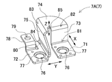
- the bus bar 7 includes a first connection portion 71 connected to one electrode terminal 13, a second connection portion 72 connected to the other electrode terminal 13, and a first bent portion 81 connected to the first connection portion 71.
- the first rising portion 73 connected to the second rising portion 73 and the second rising portion connected to the second connecting portion 72 via the second bent portion 84 and arranged in a posture intersecting with the first rising portion 73.
- the second bent portion is connected to the second rising portion 75 while being connected to the portion 75 and the first rising portion 73 via the third bent portion 82 facing the first bent portion 81. 84 and an intermediate connecting portion 74 that is connected via a fourth bent portion 83 that faces the same.
- the bus bar is connected between the first connection portion and the second connection portion connected to the opposing electrode terminals via a bent portion.
- the distance between the first connecting portion and the second connecting portion can be made closer, and flexibility is achieved. It is possible to reduce the size of the bus bar provided with. Further, this bus bar can absorb displacement in three directions of the X-axis direction, the Y-axis direction, and the Z-axis direction, and can realize high flexibility.
- the bus bar 7 has a material thickness of at least the first bent portion 81, the second bent portion 84, the third bent portion 82, and the fourth bent portion 83 at 0.8 mm to 2. It can be 0 mm.
- the battery cell 1 is a square battery having a thickness smaller than the width
- the bus bar 7 has the first connection portion 71 and the second connection portion 72 arranged in substantially the same plane, and an intermediate connection portion.
- 74 is arranged in a plane substantially parallel to the first connection portion 71 and the second connection portion 72
- the first rising portion 73 is formed as a plate extending in the thickness direction of the battery cell 1
- the second rising portion 75 is formed as a plate extending in the width direction of the battery cell 1 and is opposed to the first connection portion 71 on the side edge of the second connection portion 72. It can be connected in a vertical position along the opposite edge.
- the first rising portion in the vertical posture extended in the thickness direction of the battery cell is connected to the first connecting portion and the intermediate connecting portion via the first bent portion and the third bent portion facing each other.
- the displacement to the width direction (X-axis direction) of the battery cell in a 1st connection part and a 2nd connection part can be absorbed.
- the second rising part in the vertical posture extended in the width direction of the battery cell is connected between the second connection part and the intermediate connection part via the opposing second bent part and the fourth bent part.
- the displacement to the thickness direction (Y-axis direction) of the battery cell in a 1st connection part and a 2nd connection part can be absorbed.
- connection portion in a horizontal posture parallel to the first connection portion and the second connection portion, the first rising portion and the second rising portion through the third bent portion and the fourth bent portion intersecting each other, By connecting between these, the displacement to the perpendicular direction (Z-axis direction) in a 1st connection part and a 2nd connection part can be absorbed.
- the second connection portion 72 of the bus bar 7 has the extending portion 80 that protrudes along the edge facing the first connecting portion 71, and the second rising portion 75 extends along the extending portion 80. Can be extended.
- the second connection portion 72 of the bus bar 7 can have a connection terminal 78 protruding from one end.
- the power supply device of the present invention includes a battery cell 1 as a rectangular battery, and includes first electrode terminals 13A and second electrode terminals 13B as positive and negative electrode terminals 13 at both ends of the top surface, and a plurality of rectangular batteries are arranged in a stacked state.
- the first electrode terminal 13A is connected to the first connection portion 71
- the second electrode terminal 13B is connected to the second connection portion 72
- a plurality of batteries are connected by the bus bar 7.
- Cells 1 can be connected in series.
- the bus bar 7 has a through hole 76 into which the electrode terminal 13 is inserted in the first connection part 71 and the second connection part 72, and the electrode terminal 13 is inserted into the through hole 76,
- the electrode terminal 13 can be welded and connected to the first connection portion 71 and the second connection portion 72.
- the intermediate connecting portion 74 can include a flat surface that is pressed by a jig when the first connecting portion 71 and the second connecting portion 72 are welded.
- the first connection portion and the second connection portion can be welded while effectively contacting the electrode terminal by pressing the flat surface of the intermediate connection portion with a jig.
- the bus bar 7 can be made of aluminum or an aluminum alloy material. With the configuration described above, the bus bar is formed of a relatively easily deformable metal such as aluminum or an aluminum alloy material, so that the displacement of the pair of electrode terminals can be more effectively absorbed.
- the power supply device of the present invention includes a clad material formed by joining the bus bar 7 between the first connection portion 71 and the second connection portion 72, with the first connection portion 71 and the second connection portion 72 being different metals. can do.
- the power supply device of the present invention includes a battery cell 1 as a square battery, and includes first electrode terminals 13A and second electrode terminals 13B as positive and negative electrode terminals 13 at both ends of the top surface, and the first electrode terminal 13A is made of aluminum.
- the second electrode terminal 13B can be made of copper, and the bus bar 7 can be made of the first connecting portion 71 made of aluminum and the second connecting portion 72 made of copper.
- the power supply device of the present invention includes an insulating separator 2 interposed between adjacent battery cells 1 in a state where a plurality of battery cells 1 are stacked, and the separator 2 is connected via a bus bar 7.
- the insulating wall 15 disposed between the first electrode terminal 13 ⁇ / b> A and the second electrode terminal 13 ⁇ / b> B is provided, and the insulating wall 15 can be made higher than the electrode terminal 13 and lower than the intermediate connecting portion 74.
- the power supply device of the present invention includes an insulating separator 2 interposed between adjacent battery cells 1 in a state where a plurality of battery cells 1 are stacked, and the separator 2 is between adjacent bus bars 7.
- the insulating wall 15 can be formed higher than the bus bar 7.
- the insulating wall 15 can be provided with the support portion 16 that contacts the lower surface of the intermediate connection portion 74 of the bus bar 7 and supports the intermediate connection portion 74.
- the intermediate coupling portion can be arranged at a fixed position while being positioned.
- the bus bar can be supported by this support portion, so that the bus bar can be easily welded.
- the bus bar for battery cells is a bus bar for electrically connecting a plurality of battery cells 1 having positive and negative electrode terminals 13 between opposing electrode terminals 13, and is connected to one electrode terminal 13.
- the second rising portion 75 connected to the portion 72 via the second bent portion 84 and arranged in a posture intersecting the first rising portion 73, and the first rising portion 73 with respect to the first rising portion 73.
- the second bent portion 75 is connected to the second rising portion 75 via a fourth bent portion 83 facing the second bent portion 84 and connected to the bent portion 81 via the third bent portion 82.
- an intermediate connecting portion 74 is provided to the second rising portion 75 via a fourth bent portion 83 facing the second bent portion 84 and connected to the bent portion 81 via the third bent portion 82.
- the first rising portion, the intermediate connecting portion, and the second rising portion that are connected via the bent portion between the first connecting portion and the second connecting portion that are connected to the opposing electrode terminals.
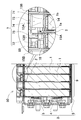
- FIG. 3 is a partially enlarged III-III cross-sectional view of the power supply device shown in FIG. 2.
- FIG. 2 It is an expansion perspective view which shows the connection structure of the bus bar of the power supply device shown in FIG.
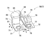
- FIG. 4 is the perspective view which looked at the state which removed the bus bar of the power supply device shown in FIG. 4 from the reverse side.
- a power supply device 100 shown in FIGS. 1 to 5 includes a plurality of battery cells 1 having positive and negative electrode terminals 13 and electrode terminals facing each other among the plurality of battery cells 1 arranged adjacent to each other. 13 is provided with a bus bar 7 that electrically connects the 13 to each other.
- the battery cell 1 is a prismatic battery in which the outer shape of the main surface, which is a wide surface, is rectangular, and is thinner than the width. Furthermore, the battery cell 1 is a secondary battery that can be charged and discharged, and is a lithium ion secondary battery. However, the power supply device of the present invention does not specify the battery cell as a square battery, nor does it specify a lithium ion secondary battery. As the battery cell, all batteries that can be charged and discharged, for example, non-aqueous electrolyte secondary batteries other than lithium ion secondary batteries, nickel-water battery cells, and the like can be used.
- the battery cell 1 is one in which an electrode body in which positive and negative electrode plates are laminated is housed in an outer can 1a, filled with an electrolyte, and hermetically sealed.
- the outer can 1a is formed in a square cylinder shape that closes the bottom, and the upper opening is air-tightly closed with a metal sealing plate 1b.
- the outer can 1a is manufactured by deep drawing a metal plate such as aluminum or aluminum alloy.
- the sealing plate 1b is made of a metal plate such as aluminum or aluminum alloy in the same manner as the outer can 1a.
- the sealing plate 1b is inserted into the opening of the outer can 1a, irradiates a laser beam to the boundary between the outer periphery of the sealing plate 1b and the inner periphery of the outer can 1a, and laser-welds the sealing plate 1b to the outer can 1a. Airtightly fixed.
- Electrode terminal 13 In the battery cell 1, positive and negative electrode terminals 13 are fixed to both ends of the sealing plate 1b that is the top surface.
- the illustrated battery cell 1 includes a first electrode terminal 13 ⁇ / b> A and a second electrode terminal 13 ⁇ / b> B as positive and negative electrode terminals 13.
- the positive and negative electrode terminals 13 are not the same metal but different metals.
- the first electrode terminal 13A that is a positive electrode is aluminum
- the second electrode terminal 13B that is a negative electrode is copper.
- the first electrode terminal 13A and the second electrode terminal 13B are fixed to the sealing plate 1b through an insulating material 14, and are connected to built-in positive and negative electrode plates (not shown), respectively. Yes.
- the positive and negative electrode terminals 13 are provided with a welding surface 13b around the protruding portion 13a.
- the welding surface 13b has a planar shape parallel to the surface of the sealing plate 1b, and a protruding portion 13a is provided at the center of the welding surface 13b.
- the protruding portion 13 a has a cylindrical shape.
- the projecting portion is not necessarily a columnar shape, and can be a polygonal column shape or an elliptical column shape (not shown).
- the position of the positive and negative electrode terminals 13 fixed to the sealing plate 1b of the battery cell 1 is a position where the positive electrode and the negative electrode are symmetrical. Thereby, the battery cell 1 can be reversed and laminated, and the positive and negative electrode terminals 13 that are adjacent to each other can be connected by the bus bar 7 and connected in series.
- the power supply device that connects the battery cells 1 in series can increase the output voltage to increase the output. However, the power supply device can also connect the battery cells in parallel and in series.
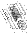
- the plurality of battery cells 1 are stacked in a state where separators 2 are interposed between adjacent battery cells 1 to form a battery stack 9, and the battery stack 9 is a fastening member. 3 is fixed to form a rectangular parallelepiped battery block 50.
- the fastening member 3 includes a pair of end plates 4 disposed on both end surfaces of the stacked battery cells 1, and battery cells in a stacked state by connecting end portions to the end plates 4. And a bind bar 5 for fixing 1 to a pressurized state.
- the battery stack 9 is formed by stacking the surfaces of the battery cells 1 on which the electrode terminals 13 are provided, in the figure, the sealing plate 1b so as to be in the same plane.
- positive and negative electrode terminals 13 are disposed on the upper surface of the battery stack 9.
- the battery stack 9 has the battery cells 1 stacked in a state where the positive and negative electrode terminals 13 at both ends of the sealing plate 1b are alternately left and right.
- the battery block 50 has a plurality of battery cells 1 arranged in a stacked state, and the first electrode terminal 13 ⁇ / b> A and the second electrode terminal 13 ⁇ / b> B are electrically connected by a bus bar at the end of the adjacent battery cell 1. Connected.
- a plurality of battery cells 1 are connected in series by a bus bar 7.
- the power supply device 100 shown in FIG. 2 is symmetrical to each other on both sides of the battery block 50 in order to connect the first electrode terminal 13A and the second electrode terminal 13B of the opposing battery cells 1 in series by the bus bar 7.
- a first bus bar 7A and a second bus bar 7B are provided.
- the first bus bar 7 ⁇ / b> A and the second bus bar 7 ⁇ / b> B are configured to be bilaterally symmetric in a plan view and a front view and to be mirror images of each other. Accordingly, the same components of the first bus bar 7A and the second bus bar 7B will be described with the same reference numerals.
- the bus bar 7 is formed by bending a metal plate.
- the bus bar 7 shown in FIGS. 6 and 7 is connected to a first connection portion 71 connected to the first electrode terminal 13 ⁇ / b> A that is one electrode terminal 13 and a second electrode terminal 13 ⁇ / b> B that is the other electrode terminal 13.
- the second rising portion 75 arranged in a posture intersecting with the first rising portion 73, and the third bent portion 82 facing the first bent portion 81 with respect to the first rising portion 73.
- an intermediate connecting portion 74 that is connected to the second rising portion 75 via a fourth bent portion 83 that faces the second bent portion 84.
- the first connection portion 71 and the second connection portion 72 are planar shapes having a rectangular outer shape, and are arranged on substantially the same plane.
- the first connection portion 71 and the second connection portion 72 have a through hole 76 into which the electrode terminal 13 is inserted.
- the first connection part 71 and the second connection part 72 are connected by welding the electrode terminal 13 to the first connection part 71 and the second connection part 72 by inserting the electrode terminal 13 into the through hole 76. Yes.
- the through hole 76 has a circular shape, and a protruding portion 13a is inserted inside.
- the circular through hole 76 has an inner shape that can guide the protruding portion 13a of the electrode terminal 13. Further, the through-hole 76 forms a gap between the inner edge and the protruding portion 13a in a state in which the protruding portion 13a is guided, so that the welding surface 13b of the electrode terminal 13 is exposed.
- first connection portion 71 and the second connection portion 72 have a peripheral edge portion of the through hole 76 as a joint surface 77 to be welded to the welding surface 13 b of the electrode terminal 13.
- the joint surface 77 is formed in a ring shape and is thinner than the first connection portion 71 and the second connection portion 72.
- the joining surface 77 has a thickness that allows laser welding to the welding surface 13b of the electrode terminal 13 with certainty.
- the thickness of the joining surface 77 is set to a dimension that can be reliably welded to the welding surface 13b by the laser beam irradiated on the surface.
- the thickness of the joining surface 77 is, for example, 0.3 mm or more, preferably 0.4 mm or more. If it is too thick, it is necessary to increase the energy for laser welding. Therefore, the thickness of the weld plate portion 33 is, for example, 2 mm or less, preferably 1.6 mm or less.
- the first rising portion 73 is connected to the first connecting portion 71 in a vertical posture.
- the first rising part 73 is connected in a vertical posture along one end of the first connection part 71 as a plate extending in the thickness direction of the battery cell 1.
- the first rising portion 73 is connected via a first bent portion 81 at the boundary with the first connecting portion 71.
- the second rising portion 75 is connected to the second connecting portion 72 in a vertical posture.
- the second rising part 75 is connected as a plate extending in the width direction of the battery cell 1 in a vertical posture along the opposing edge that is the side edge of the second connection part 72 and faces the first connection part 71.
- the second connecting portion 72 includes an extending portion 80 that protrudes along the edge facing the first connecting portion 71, and extends the second rising portion 75 along the extending portion 80.
- the second rising portion 75 shown in the figure has a trapezoidal shape whose height gradually increases from the front end side (front side in the figure) to the rear end side (rear side in the figure) of the second connection part 72.
- the second rising portion 75 is connected via a second bent portion 84 at the boundary with the second connecting portion 72.
- the intermediate connecting portion 74 is a flat surface arranged in a plane substantially parallel to the first connecting portion 71 and the second connecting portion 72, and is connected in a posture perpendicular to the upper end edge of the first rising portion 73, and The second rising portion 75 is also connected to the upper end edge in a vertical posture.
- the intermediate connecting portion 74 shown in the figure has a substantially bowl shape in plan view, and one side that is a boundary edge with the first rising portion 73 is connected by a third bent portion 82 that faces the first bent portion 81. In addition, the other side that is the boundary edge with the second rising portion 75 is connected by a fourth bent portion 83 that faces the second bent portion 84.
- the intermediate connecting portion 74 shown in the drawing is arranged in such a manner that the third bent portion 82 and the fourth bent portion 83 intersect with each other, and a notch 85 is provided at the boundary portion of these.
- the intermediate connecting portion 74 having this structure is configured to be easily deformed by the notch portion 85.
- the intermediate connecting portion 74 has a flat surface that can be pressed by a jig when welding the bus bar 7 and the electrode terminal 13.
- a jig when welding the bus bar 7 and the electrode terminal 13.
- the first rising portion 73 is designed as a plate extending in the thickness direction of the battery cell 1 so as to be connected in a vertical posture along one end of the first connection portion 71, but is not necessarily strict. It is not always bent at right angles to.
- the bus bar 7 is pressed against the electrode terminal 13 when the bus bar 7 is welded, so that the first connection portion 71 and the second connection portion 72 are in close contact with the electrode terminal 13. There is a need.
- the flat surface of the intermediate connection portion 74 can be pressed with a jig, so that the first connection portion 71 and the second connection portion are effectively provided. It becomes possible to make the connection part 72 and the electrode terminal 13 contact
- a support portion 16 that is in contact with the lower surface of the intermediate connection portion 74 may be provided at a position corresponding to the intermediate connection portion 74 on the upper end portion of the separator 2. In this way, by providing the support portion 16 that supports the intermediate connection portion 74, the bus bar 7 can be supported via the support portion 16 when the intermediate connection portion 74 is pressed by a jig. Welding can be performed easily.
- the above bus bar 7 has a first connecting portion that is connected to the first rising portion 73 in the vertical posture extended in the thickness direction of the battery cell 1 via the first bent portion 81 and the third bent portion 82 that face each other. 71 and the intermediate connecting portion 74 are connected. With this structure, the displacement in the width direction (indicated by arrow X in the drawing) of the battery cell 1 at the first connection portion 71 and the second connection portion 72 can be effectively absorbed.
- the bus bar 7 includes a second connecting portion 72, which has a second rising portion 75 in a vertical posture extended in the width direction of the battery cell 1 via a second bent portion 84 and a fourth bent portion 83 facing each other. And the intermediate connecting portion 74 are connected.
- the bus bar 7 has an intermediate connecting portion 74 in a horizontal posture parallel to the first connecting portion 71 and the second connecting portion 72 through a third bent portion 82 and a fourth bent portion 83 that intersect each other.
- the first rising portion 73 and the second rising portion 75 are connected.
- the bus bar 7 may be provided with a connection terminal 78 for detecting the voltage of the battery cell 1.
- a power supply device including a plurality of battery cells 1 connected in series
- the potential of the electrode terminals 13 of the plurality of battery cells 1 is acquired, and the voltage of each battery cell 1 is detected from the acquired potential difference.
- the bus bar 7 having the connection terminal 78 acquires a potential of the bus bar 7, that is, a potential of the electrode terminal 13 of the battery cell 1 by connecting a voltage detection line (not shown) of the voltage detection circuit to the connection terminal 78. be able to.
- the bus bar 7 according to an aspect has a connection terminal 78 coupled to the second connection portion 72.
- connection terminal 78 is provided with a connection hole 79 for fixing the voltage detection line.
- the connection terminal 78 is connected with the edge
- connection terminal 78 to which the voltage detection line is fixed is arranged on a plane substantially parallel to the second connection portion 72, the intermediate connection portion 74, and the like. According to this configuration, the connection terminal 78 can be positioned away from the electrode terminal 13 of the battery cell 1 to which the second connection portion 72 is connected.
- the voltage detection line and the bus bar are often fixed after the electrode terminals of the battery cell and the bus bar are fixed. By separating the connection terminal from the electrode terminal, a work space can be secured, and the voltage detection line and the bus bar can be easily fixed.
- the material thickness of the first bent portion 81, the second bent portion 84, the third bent portion 82, and the fourth bent portion 83 is 0.8 mm to 2.0 mm. It is preferable that the metal plate be formed by press working. If the thickness of the bus bar 7 is too thick, the first bent portion 81, the second bent portion 84, the third bent portion 82, the fourth bent portion 83, and the like are not easily deformed. It becomes difficult to obtain the effect of absorbing the displacement of the pair of electrode terminals 13 connected to each other. Moreover, if the thickness of the bus bar is too thin, the displacement of the pair of electrode terminals 13 to be connected can be absorbed to some extent even in the conventional configuration.
- the displacement of the pair of electrode terminals 13 can be effectively absorbed by adopting the above-described configuration. Further, by forming the bus bar 7 from a metal that is relatively easily deformed, such as aluminum or an aluminum alloy material, a further effect of absorbing displacement can be expected.
- the bus bar 7 is connected to the same metal as the electrode terminal 13 with the first connecting portion 71 and the second connecting portion 72 being different metals.
- the bus bar 7 connected to the battery cell 1 using copper and aluminum as the electrode terminals 13 uses the first connection portion 71 as an aluminum plate and the second connection portion 72 as a copper plate.
- the bus bar 7 shown in the figure has an aluminum plate for the first rising portion 73, the intermediate connecting portion 74, and the second rising portion 75 connected to the first connecting portion 71, and a second connecting portion 72 that is a copper plate, The two bent portions 84 are joined in close contact.
- the second connection part 72 shown in the figure has a long overall length via an extending part 80 extending toward the center part of the battery cell 1 along the facing edge with the first connection part 71.
- the joining distance between the second connecting part 72 and the second rising part 75 joined at the two-folded part 84 can be increased and the joining can be ensured.
- this bus bar 7 uses only the second connection portion 72 as a copper plate and the other portion as an aluminum plate, the amount of expensive copper plate used is reduced, and the amount of inexpensive aluminum plate used is increased to reduce the manufacturing cost. Can be reduced.
- the battery stack 9 has the separator 2 interposed between the battery cells 1, and the adjacent battery cells 1 are stacked in an insulating state. Further, the battery stack 9 is provided with an insulating wall 15 between adjacent electrode terminals 13 having a potential difference, thereby increasing a creepage distance between the electrode terminals 13 having a potential difference.
- the insulating wall 15 is integrally formed with the insulating separator 2. The insulating wall 15 is disposed at a fixed position with the separator 2 sandwiched between the battery cells 1. As shown in FIGS.
- the insulating wall 15 is located between the electrode terminals 13 having a potential difference, is higher than the electrode terminals 13, and preferably has a height protruding from the upper end of the electrode terminals 13.
- the insulating wall 15 is arranged high, and the creeping distance of the electrode terminal 13 having a potential difference can be increased.
- the insulating wall 15 shown in the drawing is between the electrode terminals 13 facing each other and between the electrode terminals 13 connected by the bus bar 7, and between the bus bars 7 adjacent to each other. And a second insulating wall 15B disposed therebetween.
- the first insulating wall 15A is formed higher than the electrode terminal 13 and insulates the battery cells 1 adjacent to each other.
- the first insulating wall 15 ⁇ / b> A is formed lower than the intermediate coupling portion 74 of the bus bar 7 so as to be disposed across the intermediate coupling portion 74 of the bus bar 7.
- the second insulating wall 15B is formed higher than the bus bar 7 and prevents the adjacent bus bars 7 from being short-circuited due to unintended contact.
- the second insulating wall 15B divides the upper surface of the battery block 50 on which the plurality of bus bars 7 are arranged into a plurality, and forms a partition region in which each bus bar 7 is arranged at a fixed position.
- Each partition region reliably insulates the bus bars 7 having a potential difference from each other by using a partition wall serving as a boundary as the second insulating wall 15B.
- the insulating wall 15 shown in FIGS. 4 and 5 includes a support portion 16 that contacts the lower surface of the intermediate connection portion 74 of the bus bar 7 and supports the intermediate connection portion 74.
- a support portion 16 that contacts the lower surface of the intermediate connection portion 74 of the bus bar 7 and supports the intermediate connection portion 74.
- two rows of vertical ribs projecting from the side surface of the second insulating wall 15 ⁇ / b> B toward the upper surface of the battery cell 1 are integrally provided as a support portion 16.
- the second insulating wall 15B shown in the drawing projects the support portion 16 so as to face the end portion where the first electrode terminal 13A where the first connection portion 71 is disposed is provided.
- the support portion 16 can support the lower surface of the intermediate connecting portion 74 and can be disposed at a fixed position while positioning the bus bar 7. In particular, when the flat surface of the intermediate connecting portion 74 is pressed with a jig, the bus bar 7 can be supported by the support portion 16 and the bus bar 7 can be easily
- the insulating wall 15 shown in FIGS. 4 and 5 includes a connecting convex portion 16 formed to face the lower surface of the connecting terminal 78 protruding from the second connecting portion 72 of the bus bar 7.
- the insulating wall 15 in FIG. 5 is a side surface of the second insulating wall 15 ⁇ / b> B, and is integrally connected with a convex portion that protrudes from the surface opposite to the support portion 16 toward the upper surface of the battery cell 1.
- the convex portion 17 is used.
- the second insulating wall 15B shown in the figure protrudes the connecting convex portion 17 so as to face the end portion where the second electrode terminal 13B where the second connection portion 72 is disposed is provided.
- the connecting projection 17 can fix a voltage detection line (not shown) through a set screw 89 inserted through the through hole 79 of the connection terminal 78.
- the connection convex part 17 of FIG. 5 is provided with a concave part 17A on the upper surface, and a nut (not shown) is fitted into the concave part 17A so as to be fixed in a non-rotating state.
- the connecting projections 17 have the connection terminals 8 disposed on the upper surface in a state where the bus bars 7 are disposed at fixed positions of the battery block 50.
- the voltage detection line can be easily and easily configured by inserting a set screw 89 into a ring-shaped terminal provided at the tip and screwing the set screw 89 through the through hole 79 of the connection terminal 78 into the nut. It is easily and surely fixed to the connection terminal 78.
- the power supply device and power supply system described above is a power supply that is mounted on an electric vehicle such as a hybrid car or an electric vehicle and supplies electric power to a traveling motor, a power supply that stores generated power of natural energy such as solar power generation or wind power generation, or It is used in various applications such as a power source for storing midnight power, and is particularly suitable as a power source suitable for high power and large current applications.
- each element constituting the present invention may be configured such that a plurality of elements are constituted by the same member and the plurality of elements are shared by one member, and conversely, the function of one member is constituted by a plurality of members. It can also be realized by sharing.
- the battery system of the present invention is optimally used for a power supply device that supplies power to a motor of a vehicle that requires a large amount of power, or a power storage device that stores natural energy or midnight power.
- DESCRIPTION OF SYMBOLS 100 Power supply device, 1 ... Battery cell, 1a ... Exterior can, 1b ... Sealing plate, 2 ... Separator, 3 ... Fastening member, 4 ... End plate, 5 ... Bind bar, 7 ... Bus bar, 7A ... 1st bus bar, 7B ... second bus bar, 9 ... battery laminate, 13 ... electrode terminal, 13A ... first electrode terminal, 13B ... second electrode terminal, 13a ... projection, 13b ... welded surface, 14 ... insulating material, 15 ... insulation Wall, 15A ... 1st insulating wall, 15B ... 2nd insulating wall, 16 ... Support part, 17 ... Connection convex part, 17A ...
- Recessed part, 50 ... Battery block, 71 ... 1st connection part, 72 ... 2nd connection 73, first rising portion, 74 ... intermediate connecting portion, 75 ... second rising portion, 76 ... through hole, 77 ... joining surface, 78 ... connecting terminal, 79 ... connecting hole, 80 ... extending portion, 81 ... first One folding part, 82 ... Third folding part, 83 ... Fourth folding part, 84 ... Two bent portions, 85 ... notch, 89 ... setscrew, 91 ... cell, 92 ... separator, 93 ... electrode terminal, 94 ... end plate, 95 ... bind bar, 97 ... bus bar, 99 ... battery stack
Landscapes
- Chemical & Material Sciences (AREA)
- Chemical Kinetics & Catalysis (AREA)
- Electrochemistry (AREA)
- General Chemical & Material Sciences (AREA)
- Inorganic Chemistry (AREA)
- Connection Of Batteries Or Terminals (AREA)
- Battery Mounting, Suspending (AREA)
Abstract
Priority Applications (3)
| Application Number | Priority Date | Filing Date | Title |
|---|---|---|---|
| US15/579,627 US10573871B2 (en) | 2015-07-30 | 2016-07-11 | Power supply device and bus bar for battery cell |
| JP2017531002A JP6847834B2 (ja) | 2015-07-30 | 2016-07-11 | 電源装置及び電池セル用のバスバー |
| CN201680044828.4A CN107851767B (zh) | 2015-07-30 | 2016-07-11 | 电源装置及电池单元用汇流条 |
Applications Claiming Priority (2)
| Application Number | Priority Date | Filing Date | Title |
|---|---|---|---|
| JP2015150283 | 2015-07-30 | ||
| JP2015-150283 | 2015-07-30 |
Publications (1)
| Publication Number | Publication Date |
|---|---|
| WO2017017915A1 true WO2017017915A1 (fr) | 2017-02-02 |
Family
ID=57884147
Family Applications (1)
| Application Number | Title | Priority Date | Filing Date |
|---|---|---|---|
| PCT/JP2016/003271 WO2017017915A1 (fr) | 2015-07-30 | 2016-07-11 | Dispositif d'alimentation, et barre omnibus pour cellule de batterie |
Country Status (4)
| Country | Link |
|---|---|
| US (1) | US10573871B2 (fr) |
| JP (1) | JP6847834B2 (fr) |
| CN (1) | CN107851767B (fr) |
| WO (1) | WO2017017915A1 (fr) |
Cited By (9)
| Publication number | Priority date | Publication date | Assignee | Title |
|---|---|---|---|---|
| JP2018152193A (ja) * | 2017-03-10 | 2018-09-27 | 株式会社東芝 | バスバー、組電池 |
| JP2018206738A (ja) * | 2017-06-09 | 2018-12-27 | 矢崎総業株式会社 | バスバー |
| WO2019187312A1 (fr) * | 2018-03-30 | 2019-10-03 | 三洋電機株式会社 | Module de batterie, véhicule équipé de celui-ci et barre omnibus |
| CN111567154A (zh) * | 2018-01-26 | 2020-08-21 | 矢崎总业株式会社 | 汇流条以及汇流条固定结构 |
| WO2020179260A1 (fr) * | 2019-03-07 | 2020-09-10 | 株式会社オートネットワーク技術研究所 | Module de câblage et module de stockage d'électricité |
| WO2021049667A1 (fr) | 2019-09-12 | 2021-03-18 | ビークルエナジージャパン株式会社 | Module de cellules secondaires |
| KR20220089476A (ko) | 2020-12-21 | 2022-06-28 | 에스케이온 주식회사 | 버스바 및 이를 포함한 배터리 모듈 |
| JP2023023709A (ja) * | 2021-08-06 | 2023-02-16 | 矢崎総業株式会社 | バスバ |
| US11621461B2 (en) | 2020-01-29 | 2023-04-04 | Toyota Motor Engineering & Manufacturing North America, Inc. | Bar module terminal assemblies having pairs of elongated terminal plates |
Families Citing this family (6)
| Publication number | Priority date | Publication date | Assignee | Title |
|---|---|---|---|---|
| CN112743749A (zh) * | 2017-04-04 | 2021-05-04 | 大山电子株式会社 | 汇流条的制造方法以及通过该制造方法而制造的汇流条 |
| WO2019188214A1 (fr) * | 2018-03-28 | 2019-10-03 | パナソニックIpマネジメント株式会社 | Barre omnibus et empilement de cellules |
| US20210305654A1 (en) * | 2018-09-19 | 2021-09-30 | Sanyo Electric Co., Ltd. | Battery module |
| WO2020090492A1 (fr) * | 2018-10-31 | 2020-05-07 | ビークルエナジージャパン株式会社 | Module de batterie |
| JP7077932B2 (ja) * | 2018-12-25 | 2022-05-31 | 株式会社オートネットワーク技術研究所 | 接続モジュール |
| CN115136406A (zh) * | 2020-03-31 | 2022-09-30 | 三洋电机株式会社 | 电源装置和具备该电源装置的车辆以及蓄电装置 |
Citations (7)
| Publication number | Priority date | Publication date | Assignee | Title |
|---|---|---|---|---|
| JP2009087761A (ja) * | 2007-09-28 | 2009-04-23 | Toshiba Corp | バスバー |
| JP2010176997A (ja) * | 2009-01-28 | 2010-08-12 | Sanyo Electric Co Ltd | 組電池及び組電池用セパレータ |
| WO2011105095A1 (fr) * | 2010-02-24 | 2011-09-01 | 三洋電機株式会社 | Module de batterie, sysème de batterie, véhicule électrique, corps mobile, dispositif de stockage électrique, dispositif d'alimentation électrique, et appareil électrique |
| DE102010019708A1 (de) * | 2010-05-07 | 2011-11-10 | Bayerische Motoren Werke Aktiengesellschaft | Speicherzellenverbinder und Speichermodul |
| JP2013020855A (ja) * | 2011-07-12 | 2013-01-31 | Sanyo Electric Co Ltd | 電源装置及び電源装置を備える車両 |
| JP2013197017A (ja) * | 2012-03-22 | 2013-09-30 | Toshiba Corp | 組電池および導電部材 |
| WO2015034585A1 (fr) * | 2013-09-06 | 2015-03-12 | Johnson Controls Technology Company | Boîtier de module de batterie et son procédé de réalisation |
Family Cites Families (6)
| Publication number | Priority date | Publication date | Assignee | Title |
|---|---|---|---|---|
| JP2007157382A (ja) * | 2005-12-01 | 2007-06-21 | Matsushita Battery Industrial Co Ltd | 組電池 |
| CN200953386Y (zh) * | 2006-09-14 | 2007-09-26 | 比亚迪股份有限公司 | 一种用于连接单元电池的连接件 |
| WO2009041735A1 (fr) * | 2007-09-27 | 2009-04-02 | Kabushiki Kaisha Toshiba | Barre omnibus |
| CN107516726A (zh) * | 2012-08-01 | 2017-12-26 | 株式会社东芝 | 电池连接器及具备该电池连接器的二次电池装置 |
| KR101688488B1 (ko) * | 2013-09-17 | 2016-12-21 | 삼성에스디아이 주식회사 | 배터리모듈 |
| AU2015394766B2 (en) * | 2015-05-08 | 2018-09-20 | Byd Company Limited | Battery cell connector |
-
2016
- 2016-07-11 JP JP2017531002A patent/JP6847834B2/ja active Active
- 2016-07-11 US US15/579,627 patent/US10573871B2/en active Active
- 2016-07-11 CN CN201680044828.4A patent/CN107851767B/zh active Active
- 2016-07-11 WO PCT/JP2016/003271 patent/WO2017017915A1/fr active Application Filing
Patent Citations (7)
| Publication number | Priority date | Publication date | Assignee | Title |
|---|---|---|---|---|
| JP2009087761A (ja) * | 2007-09-28 | 2009-04-23 | Toshiba Corp | バスバー |
| JP2010176997A (ja) * | 2009-01-28 | 2010-08-12 | Sanyo Electric Co Ltd | 組電池及び組電池用セパレータ |
| WO2011105095A1 (fr) * | 2010-02-24 | 2011-09-01 | 三洋電機株式会社 | Module de batterie, sysème de batterie, véhicule électrique, corps mobile, dispositif de stockage électrique, dispositif d'alimentation électrique, et appareil électrique |
| DE102010019708A1 (de) * | 2010-05-07 | 2011-11-10 | Bayerische Motoren Werke Aktiengesellschaft | Speicherzellenverbinder und Speichermodul |
| JP2013020855A (ja) * | 2011-07-12 | 2013-01-31 | Sanyo Electric Co Ltd | 電源装置及び電源装置を備える車両 |
| JP2013197017A (ja) * | 2012-03-22 | 2013-09-30 | Toshiba Corp | 組電池および導電部材 |
| WO2015034585A1 (fr) * | 2013-09-06 | 2015-03-12 | Johnson Controls Technology Company | Boîtier de module de batterie et son procédé de réalisation |
Cited By (19)
| Publication number | Priority date | Publication date | Assignee | Title |
|---|---|---|---|---|
| JP2018152193A (ja) * | 2017-03-10 | 2018-09-27 | 株式会社東芝 | バスバー、組電池 |
| JP2018206738A (ja) * | 2017-06-09 | 2018-12-27 | 矢崎総業株式会社 | バスバー |
| CN111567154B (zh) * | 2018-01-26 | 2022-01-11 | 矢崎总业株式会社 | 汇流条以及汇流条固定结构 |
| CN111567154A (zh) * | 2018-01-26 | 2020-08-21 | 矢崎总业株式会社 | 汇流条以及汇流条固定结构 |
| US11096300B2 (en) | 2018-01-26 | 2021-08-17 | Yazaki Corporation | Bus bar and bus bar fixation structure |
| WO2019187312A1 (fr) * | 2018-03-30 | 2019-10-03 | 三洋電機株式会社 | Module de batterie, véhicule équipé de celui-ci et barre omnibus |
| US11777178B2 (en) | 2018-03-30 | 2023-10-03 | Sanyo Electric Co., Ltd. | Battery module, vehicle provided with same, and bus bar |
| JP7200222B2 (ja) | 2018-03-30 | 2023-01-06 | 三洋電機株式会社 | 電池モジュール及びこれを備える車両並びにバスバー |
| JPWO2019187312A1 (ja) * | 2018-03-30 | 2021-03-25 | 三洋電機株式会社 | 電池モジュール及びこれを備える車両並びにバスバー |
| EP3780150A4 (fr) * | 2018-03-30 | 2021-05-26 | SANYO Electric Co., Ltd. | Module de batterie, véhicule équipé de celui-ci et barre omnibus |
| WO2020179260A1 (fr) * | 2019-03-07 | 2020-09-10 | 株式会社オートネットワーク技術研究所 | Module de câblage et module de stockage d'électricité |
| JP7140005B2 (ja) | 2019-03-07 | 2022-09-21 | 株式会社オートネットワーク技術研究所 | 電池配線モジュール及び電池パックアッセンブリ |
| JP2020145087A (ja) * | 2019-03-07 | 2020-09-10 | 株式会社オートネットワーク技術研究所 | 電池配線モジュール及び電池パックアッセンブリ |
| CN114303283A (zh) * | 2019-09-12 | 2022-04-08 | 日本汽车能源株式会社 | 二次电池模块 |
| WO2021049667A1 (fr) | 2019-09-12 | 2021-03-18 | ビークルエナジージャパン株式会社 | Module de cellules secondaires |
| US11621461B2 (en) | 2020-01-29 | 2023-04-04 | Toyota Motor Engineering & Manufacturing North America, Inc. | Bar module terminal assemblies having pairs of elongated terminal plates |
| KR20220089476A (ko) | 2020-12-21 | 2022-06-28 | 에스케이온 주식회사 | 버스바 및 이를 포함한 배터리 모듈 |
| EP4027446A2 (fr) | 2020-12-21 | 2022-07-13 | SK Innovation Co., Ltd. | Barre omnibus et module de batterie la comprenant |
| JP2023023709A (ja) * | 2021-08-06 | 2023-02-16 | 矢崎総業株式会社 | バスバ |
Also Published As
| Publication number | Publication date |
|---|---|
| CN107851767A (zh) | 2018-03-27 |
| JP6847834B2 (ja) | 2021-03-24 |
| JPWO2017017915A1 (ja) | 2018-05-17 |
| CN107851767B (zh) | 2020-10-30 |
| US20180151862A1 (en) | 2018-05-31 |
| US10573871B2 (en) | 2020-02-25 |
Similar Documents
| Publication | Publication Date | Title |
|---|---|---|
| WO2017017915A1 (fr) | Dispositif d'alimentation, et barre omnibus pour cellule de batterie | |
| JP6907131B2 (ja) | 電源装置及びこれを用いる車両並びにバスバー | |
| US20140295235A1 (en) | Battery module | |
| WO2017130706A1 (fr) | Dispositif d'alimentation électrique ainsi que véhicule mettant en œuvre celui-ci, barres omnibus, et procédé de connexion électrique d'éléments de batterie mettant en œuvre ces barres omnibus | |
| JP6269383B2 (ja) | 蓄電装置 | |
| JP6467211B2 (ja) | 蓄電モジュール | |
| JP7024735B2 (ja) | 蓄電装置 | |
| JP2011060623A (ja) | 組電池 | |
| JP5589955B2 (ja) | 角形二次電池 | |
| WO2020035970A1 (fr) | Module de batterie | |
| JP7163932B2 (ja) | 蓄電素子 | |
| EP2843731A2 (fr) | Module de batterie | |
| JP2017216095A (ja) | 電池モジュール | |
| WO2019124109A1 (fr) | Barre omnibus, et empilement de cellules | |
| JP6556986B2 (ja) | 蓄電装置 | |
| JP2014022238A (ja) | 電池パック | |
| JP7075580B2 (ja) | ラミネート型電池モジュール | |
| JP6984408B2 (ja) | 蓄電素子の製造方法、及び、蓄電素子 | |
| JP2020047502A (ja) | 蓄電装置の製造装置及び蓄電装置の製造方法 | |
| JP6186782B2 (ja) | 蓄電素子 | |
| JP2019061893A (ja) | 蓄電素子 | |
| WO2024058235A1 (fr) | Dispositif de stockage d'énergie | |
| JP7059548B2 (ja) | 蓄電素子 | |
| JP6926899B2 (ja) | 蓄電素子 | |
| JP6394749B2 (ja) | 蓄電装置 |
Legal Events
| Date | Code | Title | Description |
|---|---|---|---|
| 121 | Ep: the epo has been informed by wipo that ep was designated in this application |
Ref document number: 16830023 Country of ref document: EP Kind code of ref document: A1 |
|
| ENP | Entry into the national phase |
Ref document number: 2017531002 Country of ref document: JP Kind code of ref document: A |
|
| WWE | Wipo information: entry into national phase |
Ref document number: 15579627 Country of ref document: US |
|
| NENP | Non-entry into the national phase |
Ref country code: DE |
|
| 122 | Ep: pct application non-entry in european phase |
Ref document number: 16830023 Country of ref document: EP Kind code of ref document: A1 |