WO2017017870A1 - ガラス板の加工装置 - Google Patents
ガラス板の加工装置 Download PDFInfo
- Publication number
- WO2017017870A1 WO2017017870A1 PCT/JP2016/002349 JP2016002349W WO2017017870A1 WO 2017017870 A1 WO2017017870 A1 WO 2017017870A1 JP 2016002349 W JP2016002349 W JP 2016002349W WO 2017017870 A1 WO2017017870 A1 WO 2017017870A1
- Authority
- WO
- WIPO (PCT)
- Prior art keywords
- glass plate
- grinding
- grinding work
- axis direction
- work table
- Prior art date
Links
- 239000011521 glass Substances 0.000 title claims abstract description 201
- 238000005520 cutting process Methods 0.000 claims description 13
- 238000000034 method Methods 0.000 claims description 10
- 239000006121 base glass Substances 0.000 claims description 4
- 239000005337 ground glass Substances 0.000 claims description 2
- 238000007599 discharging Methods 0.000 abstract 1
- 230000032258 transport Effects 0.000 description 35
- 238000003825 pressing Methods 0.000 description 9
- 238000004519 manufacturing process Methods 0.000 description 6
- 230000015572 biosynthetic process Effects 0.000 description 4
- 230000002093 peripheral effect Effects 0.000 description 4
- 239000005357 flat glass Substances 0.000 description 2
- 238000001179 sorption measurement Methods 0.000 description 2
- 239000006063 cullet Substances 0.000 description 1
- 230000007547 defect Effects 0.000 description 1
- 238000000605 extraction Methods 0.000 description 1
- 238000003780 insertion Methods 0.000 description 1
- 230000037431 insertion Effects 0.000 description 1
- 238000000926 separation method Methods 0.000 description 1
Images


Classifications
-
- B—PERFORMING OPERATIONS; TRANSPORTING
- B24—GRINDING; POLISHING
- B24B—MACHINES, DEVICES, OR PROCESSES FOR GRINDING OR POLISHING; DRESSING OR CONDITIONING OF ABRADING SURFACES; FEEDING OF GRINDING, POLISHING, OR LAPPING AGENTS
- B24B9/00—Machines or devices designed for grinding edges or bevels on work or for removing burrs; Accessories therefor
- B24B9/02—Machines or devices designed for grinding edges or bevels on work or for removing burrs; Accessories therefor characterised by a special design with respect to properties of materials specific to articles to be ground
- B24B9/06—Machines or devices designed for grinding edges or bevels on work or for removing burrs; Accessories therefor characterised by a special design with respect to properties of materials specific to articles to be ground of non-metallic inorganic material, e.g. stone, ceramics, porcelain
- B24B9/08—Machines or devices designed for grinding edges or bevels on work or for removing burrs; Accessories therefor characterised by a special design with respect to properties of materials specific to articles to be ground of non-metallic inorganic material, e.g. stone, ceramics, porcelain of glass
- B24B9/10—Machines or devices designed for grinding edges or bevels on work or for removing burrs; Accessories therefor characterised by a special design with respect to properties of materials specific to articles to be ground of non-metallic inorganic material, e.g. stone, ceramics, porcelain of glass of plate glass
-
- B—PERFORMING OPERATIONS; TRANSPORTING
- B24—GRINDING; POLISHING
- B24B—MACHINES, DEVICES, OR PROCESSES FOR GRINDING OR POLISHING; DRESSING OR CONDITIONING OF ABRADING SURFACES; FEEDING OF GRINDING, POLISHING, OR LAPPING AGENTS
- B24B41/00—Component parts such as frames, beds, carriages, headstocks
- B24B41/02—Frames; Beds; Carriages
-
- B—PERFORMING OPERATIONS; TRANSPORTING
- B24—GRINDING; POLISHING
- B24B—MACHINES, DEVICES, OR PROCESSES FOR GRINDING OR POLISHING; DRESSING OR CONDITIONING OF ABRADING SURFACES; FEEDING OF GRINDING, POLISHING, OR LAPPING AGENTS
- B24B41/00—Component parts such as frames, beds, carriages, headstocks
- B24B41/06—Work supports, e.g. adjustable steadies
- B24B41/068—Table-like supports for panels, sheets or the like
-
- B—PERFORMING OPERATIONS; TRANSPORTING
- B65—CONVEYING; PACKING; STORING; HANDLING THIN OR FILAMENTARY MATERIAL
- B65G—TRANSPORT OR STORAGE DEVICES, e.g. CONVEYORS FOR LOADING OR TIPPING, SHOP CONVEYOR SYSTEMS OR PNEUMATIC TUBE CONVEYORS
- B65G49/00—Conveying systems characterised by their application for specified purposes not otherwise provided for
- B65G49/05—Conveying systems characterised by their application for specified purposes not otherwise provided for for fragile or damageable materials or articles
- B65G49/06—Conveying systems characterised by their application for specified purposes not otherwise provided for for fragile or damageable materials or articles for fragile sheets, e.g. glass
- B65G49/063—Transporting devices for sheet glass
- B65G49/064—Transporting devices for sheet glass in a horizontal position
-
- B—PERFORMING OPERATIONS; TRANSPORTING
- B65—CONVEYING; PACKING; STORING; HANDLING THIN OR FILAMENTARY MATERIAL
- B65G—TRANSPORT OR STORAGE DEVICES, e.g. CONVEYORS FOR LOADING OR TIPPING, SHOP CONVEYOR SYSTEMS OR PNEUMATIC TUBE CONVEYORS
- B65G49/00—Conveying systems characterised by their application for specified purposes not otherwise provided for
- B65G49/05—Conveying systems characterised by their application for specified purposes not otherwise provided for for fragile or damageable materials or articles
- B65G49/06—Conveying systems characterised by their application for specified purposes not otherwise provided for for fragile or damageable materials or articles for fragile sheets, e.g. glass
- B65G49/063—Transporting devices for sheet glass
- B65G49/066—Transporting devices for sheet glass being suspended; Suspending devices, e.g. clamps, supporting tongs
-
- C—CHEMISTRY; METALLURGY
- C03—GLASS; MINERAL OR SLAG WOOL
- C03B—MANUFACTURE, SHAPING, OR SUPPLEMENTARY PROCESSES
- C03B33/00—Severing cooled glass
- C03B33/02—Cutting or splitting sheet glass or ribbons; Apparatus or machines therefor
-
- C—CHEMISTRY; METALLURGY
- C03—GLASS; MINERAL OR SLAG WOOL
- C03B—MANUFACTURE, SHAPING, OR SUPPLEMENTARY PROCESSES
- C03B33/00—Severing cooled glass
- C03B33/02—Cutting or splitting sheet glass or ribbons; Apparatus or machines therefor
- C03B33/023—Cutting or splitting sheet glass or ribbons; Apparatus or machines therefor the sheet or ribbon being in a horizontal position
- C03B33/027—Scoring tool holders; Driving mechanisms therefor
-
- C—CHEMISTRY; METALLURGY
- C03—GLASS; MINERAL OR SLAG WOOL
- C03B—MANUFACTURE, SHAPING, OR SUPPLEMENTARY PROCESSES
- C03B33/00—Severing cooled glass
- C03B33/02—Cutting or splitting sheet glass or ribbons; Apparatus or machines therefor
- C03B33/023—Cutting or splitting sheet glass or ribbons; Apparatus or machines therefor the sheet or ribbon being in a horizontal position
- C03B33/033—Apparatus for opening score lines in glass sheets
-
- C—CHEMISTRY; METALLURGY
- C03—GLASS; MINERAL OR SLAG WOOL
- C03C—CHEMICAL COMPOSITION OF GLASSES, GLAZES OR VITREOUS ENAMELS; SURFACE TREATMENT OF GLASS; SURFACE TREATMENT OF FIBRES OR FILAMENTS MADE FROM GLASS, MINERALS OR SLAGS; JOINING GLASS TO GLASS OR OTHER MATERIALS
- C03C19/00—Surface treatment of glass, not in the form of fibres or filaments, by mechanical means
-
- B—PERFORMING OPERATIONS; TRANSPORTING
- B65—CONVEYING; PACKING; STORING; HANDLING THIN OR FILAMENTARY MATERIAL
- B65G—TRANSPORT OR STORAGE DEVICES, e.g. CONVEYORS FOR LOADING OR TIPPING, SHOP CONVEYOR SYSTEMS OR PNEUMATIC TUBE CONVEYORS
- B65G2249/00—Aspects relating to conveying systems for the manufacture of fragile sheets
- B65G2249/04—Arrangements of vacuum systems or suction cups
Definitions
- the present invention relates to a glass plate processing apparatus that cuts out a glass plate such as a glass plate for a window glass of an automobile and a glass plate for other uses from a base plate glass plate, and performs grinding processing on the periphery of the cut glass plate.
- the present invention connects a glass plate scribing device, a splitting device, and a grinding device through an adsorption conveyance device, and cuts out the glass plate continuously cut out from the scribing device and the splitting device.
- the present invention relates to a glass plate processing apparatus which is supplied one after another to a grinding processing apparatus, continuously grinds, and takes out one after another.
- the present invention relates to a glass plate processing apparatus in which a scribe portion, a folding portion, a grinding processing portion, and a glass plate conveying device are operated under NC control.
- the glass plate processing apparatuses described in Patent Documents 1 and 2 both connect a split-splitting device and a grinding device via a glass-plate transport device, and sequentially cut the glass plates cut out from the split-splitting device. Is supplied to a grinding machine, continuously ground, and sequentially taken out.
- the present invention eliminates the above-mentioned defects and can increase the production speed. In addition, it can obtain a grinding process with high accuracy and uniform dimensions, and further increase the supply of the glass plate to the grinding work table. It is in providing the processing apparatus of the glass plate which can be performed accurately.
- the glass plate processing apparatus of the present invention includes two grinding work tables that perform NC control movement or angle control rotation independently of each other, and one machine that performs NC control movement corresponding to the two grinding work tables.
- the two grinding work tables alternately move in the plane coordinate system in cooperation with the grinding head, and one grinding work table holds the glass plate and is ground by the grinding head.
- the other grinding work table repeatedly carries out the glass plate unloading operation and the next glass plate receiving operation alternately so that the grinding head continuously grinds the glass plates received one after another. It becomes.
- the processing apparatus of the glass plate of this invention moves independently from each other in the Y-axis direction orthogonal to the conveyance direction of a glass plate by this glass plate conveyance apparatus and this glass plate conveyance apparatus, and is arranged in the conveyance direction of a glass plate
- the two grinding work tables and one grinding head moving in the X-axis direction parallel to the conveying direction are provided, and the two grinding work tables are ground by the grinding head for the held glass plate. Processing, and during this grinding process, the unloading of the glass plate after grinding and the receiving and holding of the next glass plate are repeated alternately, and one grinding head includes a grinding work table holding the glass plate, XY plane coordinate system movement is performed alternately, and grinding is continuously performed.
- the glass plate processing apparatus of the present invention includes two grinding work tables that rotate independently of each other in angle control and move in the Y-axis direction orthogonal to the conveying direction of the glass plate, and these two grinding tables.
- a grinding head that alternately moves in the plane polar coordinate system in cooperation with each of the work tables, and the two grinding work tables are arranged in series in the conveyance direction of the glass plate, The grinding head is moved in the X-axis direction in the conveying direction of the glass plate so as to be alternately arranged at a position corresponding to each of the two grinding work tables.
- the other grinding work table While holding the glass plate and grinding by the grinding head, the other grinding work table alternately repeats the operation of carrying out the glass plate and receiving the next glass plate, and the grinding head continuously performs the grinding process. It has been kicking way.
- two grinding work tables are provided in the grinding position, and the two grinding work tables are NC-controlled independently of each other, and alternately share one grinding head and NC. Grinding is performed by moving the coordinates of the control.
- the other grinding work table stops at the origin
- the grinding head proceeds to the other grinding work table and continuously performs the grinding process.
- the grinding head performs grinding processing alternately or alternately on the glass plates of the two grinding work tables and does not require standby stop after returning to the standby point. High production capacity can be obtained.
- the glass plates of the two grinding work tables are ground by one grinding head, there is no variation in the grinding processing dimensions of the glass plates of the two work tables.
- the finish is constant.
- the two grinding work tables are NC controlled independently of each other, so that the two grinding work tables grind glass plates having different sizes and shapes. Processing can be performed.
- the grinding work table is cooperated with two grinding work tables that are moved under NC control and the glass plate transfer device that is also NC controlled and transports the glass plate.
- the glass plate can be handed with high positional accuracy, and it can be handed accurately to the contour locus of the grinding process.
- the present invention it is possible to increase the production speed, and in addition, it is possible to obtain a grinding process with high accuracy and uniform dimensions, and further, processing of a glass plate capable of supplying and supplying the glass plate to the grinding work table with high accuracy.
- An apparatus can be provided.
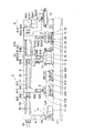
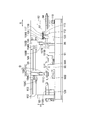
- FIG. 1 is an explanatory front view of a specific example according to the present invention.
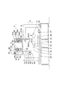
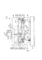
- FIG. 2 is an explanatory rear view of the example shown in FIG. 3 is a cross-sectional explanatory view taken along the line III-III in FIG. 4 is a cross-sectional explanatory view taken along the line IV-IV in FIG.
- FIG. 5 is a cross-sectional explanatory view taken along the line VV in FIG.
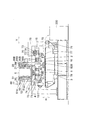
- FIG. 6 is an explanatory front view of another specific example of the present invention.
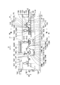
- FIG. 7 is an explanatory rear view of the example shown in FIG.
- FIG. 8 is a cross-sectional explanatory view taken along line VIII-VIII in FIG.
- FIG. 9 is a cross-sectional explanatory view taken along the line IX-IX in FIG.
- the glass plate processing apparatus 1 of this example includes a base 3 installed on a floor surface, and is an X direction that is one direction in a horizontal plane of the base 3. At both ends (hereinafter referred to as the X-axis direction), columns 4 are erected, and the column 4 is provided with a gantry 6 that bridges the columns 4 and extends in the X-axis direction.
- the glass plate processing apparatus 1 that performs the above is provided with an entry position 7, a scribe position 8, a folding position 9, a grinding position 10, and an extraction position 11.
- the entry table 7 is provided with an entry table 12, the scribe position 8 is provided with a scribe work table 13 and a scribe head 14, and the folding position 9 is provided with a folding device 15 and a folding belt conveyor 16.
- the scribe position 8 is provided with a scribe work table 13 and a scribe head 14
- the folding position 9 is provided with a folding device 15 and a folding belt conveyor 16.
- two grinding work tables 17A and 17B and one grinding head 18 are provided at the take-out position 10.
- a take-out conveyor 19 is provided.
- a table is placed on the back surface 21 of the gantry 6 above the take-up table 19, the inward table 12, the scribe work table 13, the folding belt conveyor 16, the two grinding work tables 17 ⁇ / b> A and 17 ⁇ / b> B, and the take-out conveyor 19. 6, that is, along the X-axis direction.
- the scribe work table 13 includes a table main body 22 that flatly supports the glass plate 2 on the upper surface, a table support base 23 that fixes and supports the table main body 22, and a Y direction orthogonal to the X axis direction in the horizontal plane (hereinafter referred to as the Y axis direction). And Y-axis moving means 24 for moving the table support 23.
- the Y-axis moving means 24 is installed on two guide rails 25 arranged in parallel on the upper surface of the base 3 along the Y-axis direction, and a slide block held by these guide rails 25 so as to be movable in the Y-axis direction.
- the Y-axis moving table 26, the Y-axis moving table 26 connected to the Y-axis moving table 26 via a screw nut and a rotatable feed screw 27 provided between the guide rails 25, and the Y-axis control connected to one end of the feed screw 27.
- a motor 28 is provided to two guide rails 25 arranged in parallel on the upper surface of the base 3 along the Y-axis direction, and a slide block held by these guide rails 25 so as to be movable in the Y-axis direction.
- the Y-axis moving table 26 the Y-axis moving table 26 connected to the Y-axis moving table 26 via a screw nut and a rotatable feed screw 27 provided between the guide rails
- the table body 22 attached to the Y-axis moving table 26 via the table support table 23 is arranged in the Y-axis direction of the Y-axis moving table 26 via a screw nut when the feed screw 27 is rotated by the drive of the Y-axis control motor 28. It is also moved in the Y-axis direction by movement.
- the scribing head 14 that is moved in the X-axis direction corresponding to the width of the table body 22 in the X-axis direction is provided on the front surface 36 of the gantry 6 via the X-axis moving means 37.
- the X-axis moving means 37 includes two guide rails 49 arranged in parallel on the front surface 36 in a range in the X-axis direction that exceeds the width of the table body 22 in the X-axis direction, and is movable in the X-axis direction with respect to these guide rails 49.
- An X-axis moving table 38 fixed to the held slide block, a rotatable feed screw 39 provided between the guide rails 49 on the front surface 36, and an X-axis control motor 40 connected to the feed screw 39 are provided. is doing.
- the bearing device 41 attached to the X-axis moving table 38 moves along the X-axis by a built-in bearing (not shown) with a rotational axis center orthogonal to the XY plane that is a horizontal plane, that is, the upper surface of the glass plate 2.
- a rotary shaft 42 is held so as to be rotatable with respect to the base 38, and a rotary shaft 42 to which the scribe head 14 is attached via a bracket 43 is provided at the lower end portion.
- a scribing head main body 44 is attached via 43, and an output rotation shaft of the angle control motor 45 is connected to the upper end via spur gears 44a and 44b.
- the scribe head 14 includes a bracket 43 attached to a lower end portion of the rotating shaft 42 and a scribe head main body 44.
- the scribe head main body 44 includes a cutter wheel 46 at the lower end.
- an air cylinder device 48 that is attached to the upper portion of the cutter head 47 and moves the cutter wheel 46 up and down and applies a cutting pressure to the cutter wheel 46 during scribing.
- the angle control motor 45 moves a cutter wheel 46 arranged on the rotation axis of the rotation shaft 42 around the rotation axis perpendicular to the upper surface of the glass plate 2 via the spur gears 44 a and 44 b and the rotation shaft 42. By controlling the angle, the direction of the cutting edge of the cutter wheel 46 is adjusted to the scribe direction.
- Each of the two grinding work tables 17A and 17B which adsorb the glass plate 2 on the upper surface and are alternately moved in the Y-axis direction independently of each other, has a plurality of suction cups 29 adsorbing the glass plate 2 on the upper surface.
- Each of the suction cups 29 includes a table base 30A and 30B on which each of the suction cups 29 is detachably mounted, and each of the table bases 30A and 30B is attached to each of the Y-axis moving means 31A and 31B. ing.
- the Y-axis moving means 31A for the table base 30A is a pair of guide rails 32A arranged in parallel along the Y-axis direction on the upper surface of the base 3, and is held by these guide rails 32A so as to be movable in the Y-axis direction.
- a nut 36A screwed to the feed screw 34A and a Y-axis control motor 35A connected to one end of the feed screw 34A are provided.
- the grinding work table 17A having the table base 30A is composed of a Y-axis control motor. It is guided by the guide rail 32A by the drive of 35A and is moved in the Y-axis direction.
- the Y-axis moving unit 31B for the table base 30B includes a pair of guide rails 32B arranged side by side along the Y-axis direction on the upper surface of the base 3, and the Y-axis moving unit A slide block 33B that is movably held in the direction, a feed screw 34B that is rotatably provided on the upper surface of the base 3 between the guide rails 32B in the X-axis direction, and is fixed to the table base 30B on the one hand, , A nut 36B screwed to the feed screw 34B, and a Y-axis control motor 35B connected to one end of the feed screw 34B, and the grinding work table 17B equipped with the table base 30B includes a Y-axis control motor 35B. It is guided by the guide rail 32B by driving and moved in the Y-axis direction.
- one grinding head 18 that alternately moves in the X-axis direction corresponding to the movement in the Y-axis direction of the grinding work tables 17 ⁇ / b> A and 17 ⁇ / b> B is provided via the X-axis moving means 50.
- the X-axis moving means 50 includes a pair of guide rails 51 arranged side by side on the gantry 6 in the X-axis direction movement range corresponding to the X-axis direction arrangement range of the grinding work tables 17A and 17B, and the guide rail 51
- An X-axis moving table 52 integrally fixed to a slide block 51a held so as to be movable in the X-axis direction, and a guide rail 51 in the vertical direction H are connected to the X-axis moving table 52 via nuts.
- a feed screw 53 provided between them and an X-axis control motor 54 connected to one end of the feed screw 53 are provided.
- the X-axis moving table 52 is ground by the drive of the X-axis control motor 54. Moves in the X-axis direction relative Kuteburu 17A and 17B.
- the grinding head 18 having the grinding head main body 58 attached to the X-axis moving table 52 through the bearing device 55 moves alternately in the X-axis direction with respect to the grinding work tables 17A and 17B. Yes.
- the bearing device 55 attached to the X-axis moving table 52 can freely rotate a rotating shaft 56 having an axis center orthogonal to the XY plane coordinate system, that is, the upper surface of the glass plate 2, via a bearing (not shown).
- the grinding head main body 58 is attached to the lower end portion of the rotation shaft 56 via a bracket 57, while the upper end portion 59 is attached to the output rotation shaft of the angle control motor 60.
- a spur gear 61 that meshes with the spur gear is attached.
- the grinding head main body 58 includes a spindle motor 63 having an output rotation shaft to which a grinding wheel 62 is attached, and the position of the spindle motor 63 and, in turn, the position of the grinding working portion of the grinding wheel 62 with respect to the glass plate 2 are orthogonal to each other. And a slide device 64 that adjusts in the direction, the grinding working portion of the grinding wheel 62 is positioned on the rotation axis of the rotation shaft 56, and the angle control motor 60 controls the angle of the rotation shaft 56 to change the glass.
- the grinding wheel 62 is swung around the grinding work part corresponding to the peripheral shape of the plate 2, and the grinding wheel 62 always grinds the peripheral edge of the glass plate 2 at a constant angle.
- the folding position 9 includes a folding belt conveyor 16 on which the glass plate 2 on which a scribe line is formed at the scribe position 8 is placed, and a folding of the glass plate 2 placed on the folding belt conveyor 16. Two folding devices 15 are provided.
- Each of the folding devices 15 includes an end-cutting cutter device 70, a press device 71, and a moving means 72 that holds the end-cutting cutter device 70 and the pressing device 71 and moves them along the upper surface of the glass plate 2. It has.
- Each moving means 72 holds the end-cutting cutter device 70 and the press device 71, and moves in the X-axis direction while holding the Y-direction moving device 73 and the Y-direction moving device 73 for NC control movement in the Y-axis direction.
- X direction moving device 74 is provided, one X direction moving device 74 is on the gantry 6, and the other X direction moving device 74 is on the standing body 75 from the base 3 via a bracket 76. Installed.
- the folding belt conveyor 16 includes a conveyor belt 77, a support plate and frame 78 that supports the conveyor belt 77 in a planar shape from the inside and is supported by the base 3, and a drive device 79 that rotates the conveyor belt 77. is doing.
- the glass plate 2 on which the scribe line is formed at the scribe position 8 is placed on the split belt conveyor 16 by the suction cup 82A of the transport shuttle 81A corresponding to the scribe position 8.
- the cutting cutter device 70 was sequentially moved to the required location, and the end cutting line was put on the glass plate 2 by each end cutting cutter device 70, and then each press device 71 was moved sequentially to the required location, and the end cutting line was put.
- the glass plate 2 is pressed by each pressing device 71, the unnecessary portion is broken and separated, and the glass plate 2 from which the unnecessary portion has been separated is transported to the folding position 9.
- the glass plate transfer device 20 is inserted into the back surface 21 of the gantry 6 from the upper side of the table 12 to the upper side of the conveyor 19 and a pair of guide rails 83, and the guide rail 83 in the X-axis direction via a slide block.
- the guide rail 83 is aligned.
- a rack 84 shared with the transport shuttles 81A, 81B and 81C is provided.
- the transport shuttle 81A includes a bracket 90A, a travel motor 85A attached to the bracket 90A and a pair of glass plate suction lifting devices 87A1 and 87A2, and the transport shuttle 81B travels attached to the bracket 90B and the bracket 90B.
- the transport shuttle 81C includes a motor 85B and a glass plate suction lifting device 87B, and the transport shuttle 81C includes a traveling motor 85C and a glass plate suction lifting device 87C attached to the bracket 90C, respectively.
- 90C are supported by a pair of guide rails 83 through a slide block so as to be movable in the X-axis direction.
- a pinion gear 86A is provided on the output rotation shaft of the travel motor 85A
- a pinion gear 86B is provided on the output rotation shaft of the travel motor 85B
- a pinion gear 86C is provided on the output rotation shaft of the travel motor 85C.
- the gear racks 84 are engaged with each other.
- the transport shuttles 81A, 81B, and 81C are configured to reciprocate in the X-axis direction at a necessary distance independently from each other by independent control driving of the respective traveling motors 85A, 85B, and 85C.
- the glass plate suction lifting device 87A1 includes a plurality of suction cups 82A1 for suctioning and releasing the glass plate 2, and a lifting device 89A1 to which the suction cup 82A1 is attached and lifting the suction cup 82A1, and a glass plate suction lifting and lowering device 87A2.
- a plurality of suction cups 82A2 for sucking and releasing the glass plate 2 a lifting device 89A2 to which the suction cup 82A2 is attached and moving the suction cup 82A2, and a glass plate suction lifting device 87B
- a glass plate suction lifting and lowering device 87C performs suction and suction release of the glass plate 2.
- the transport shuttle 81A having the two glass plate suction lifting devices 87A1 and 87A2 is operated by the traveling motor 85A, and the glass plate suction lifting device 87A1 is inserted above the table 12 at the return end in the X-axis direction.
- the glass plate suction lifting device 87A2 is positioned above the scribe work table 13, while the glass plate suction lifting device 87A2 is positioned above the folding belt conveyor 16 at the forward end thereof. Reciprocating so that the glass plate 2 is inserted into the scribing work table 13 from the entrance table 12 and from the scribing table 13 onto the folding belt conveyor 16 so that the apparatus 87A1 is positioned above the scribing work table 13. Is to repeat.
- the transport shuttle 81B is moved back and forth between the folding belt conveyor 16 and the grinding work tables 17A and 17B by the operation of the driving motor 85B, and the glass plate is folded on the folding belt conveyor 16. 2 are conveyed alternately to the grinding work table 17A and the grinding work table 17B.
- the transport shuttle 81C alternately takes out the ground glass plates 2 on the grinding work tables 17A and 17B and carries them out to the conveyor 19 by the operation of the traveling motor 85C.
- the glass plate transport device 20 operates as the operation starts, and the suction cup 82 ⁇ / b> A ⁇ b> 1 descends on the entry table 12, and the glass plate 2 that is the raw glass plate on the entry table 12 is sucked and lifted.
- the transport shuttle 81A moves forward and the suction cup 82A1 that sucks the glass plate 2 reaches above the scribe work table 13
- the suction cup 82A1 descends to release the suction to the glass plate 2
- the glass plate 2 is placed on the scribe work table 13.
- the suction cup 82A1 placed and emptied rises and returns to the entry table 12 by the backward movement of the transport shuttle 81A.
- the scribe work table 13 corresponds to the scribe work table 13.
- the scribe head 14 and the scribe work table The scribe line 13 is moved to the XY coordinates, and a scribe line is formed on the glass plate 2 by the cutter wheel 46.
- the scribe head 14 and the scribe work table 13 return to the origin, and then the scribe line is formed.
- the suction cup 82A2 returned to the work table 13 descends, sucks and lifts the glass plate 2 with the scribe line, and the glass plate 2 sucked and lifted by the suction cup 82A2 moves toward the folding position 9 by the forward movement of the transport shuttle 81A.
- the suction cup 82A2 When the suction cup 82A2 that has been transported and sucked the glass plate 2 with the scribe line reaches the split position 9, the suction cup 82A2 is lowered to release the suction to the base glass 2 with the scribe line, When the base glass 2 is placed on the folding belt conveyor 16, the suction cup 82A2 Returning to the upper side of the table 13, instead, at the folding position 9, the transport shuttle 81 ⁇ / b> B corresponding to the folding position 9 is restored, and the suction cup 82 ⁇ / b> B is immediately lowered and placed on the folding belt conveyor 16. The glass plate 2 containing the scribe line is adsorbed by the suction cup 82B and pressed onto the folding belt conveyor 16 so as not to move.
- each folding device 15 operates, and the end-cutting cutter device 70 and the pressing device 71 are Move over the glass plate 2 containing the scribe line, cut the edge to the required position, and then perform the pressing operation to split and separate the unnecessary portion of the outer area along the scribe line, to produce the cut glass plate 2,
- the suction cup 82B that continues to adsorb the cut glass plate 2 rises as it is, lifts the cut glass plate 2, and carries the glass plate 2 cut by the suction cup 82B while sucking and lifting it.
- the feed shuttle 81B starts to move toward the grinding position 10, and at this time, at the grinding position 10, one of the two grinding work tables 17A and 17B is inserted into the grinding work table 17A via the suction cup 29.
- the adsorbed glass plate 2 is in the process of grinding the periphery thereof by XY coordinate movement between the one grinding work table 17A and the grinding head 18, and the other grinding work table 17B returns to the origin, and the transport shuttle 81C.
- the suction cup 82B sucks the cut glass plate 2 on the conveyor belt 77, and the suction cup 82B is moved above the grinding work table 17B by the transport shuttle 81B, so that the grinding work table Lowers toward 17B and sucks and opens suction cup 82B on grinding work table 17B
- the cut glass plate 2 is carried on and placed on the grinding work table 17B.
- the grinding work table 17B sucks and fixes the received cut glass plate 2 through the suction cup 29, and goes toward the grinding area.
- the grinding head 18 proceeds to the grinding work table 17B in synchronization with the end of the grinding work of the grinding work table 17A that has been previously performed, and moves to the grinding work table 17B to move the XY coordinates with the grinding work table 17B.
- the periphery of the newly cut glass plate 2 on the table 17B is ground.
- the grinding work tables 17 ⁇ / b> A and 17 ⁇ / b> B alternately move the grinding head 18 and the plane coordinate system, and one grinding work table 17 ⁇ / b> A or 17 ⁇ / b> B holds the glass plate 2.
- the other grinding work table 17 B or 17 A alternately repeats the operation of carrying out the glass plate 2 and receiving the glass plate 2, and the grinding head 18 continuously moves the glass plate 2. Peripheral grinding is performed.
- the glass plate processing apparatus 1A of the present example shown in FIGS. 6 to 9 also includes a base 91 installed on the floor surface, and supports 92 stand on both ends of the base 91 in the X-axis direction.
- the support frame 92 is provided with a support frame 93 extending in the X-axis direction by bridging the support columns 92.
- the glass plate processing apparatus 90 is provided with an entry position 94, a scribe and split position 95, a grinding position 96 and a take-out position 128.
- the glass plate 2 is fixed at the same position. As it is, scribe line formation on the glass plate 2 and split separation (production of the cut out glass plate 2) with respect to the glass plate 2 on which the scribe lines are formed are performed.
- a scribe line and end line forming and pressing device 97 is provided in the entry position 94 and the scribing and splitting position 95.
- a scribe line and end line forming and pressing device 97 is provided in the grinding position 96.
- two grinding work tables 98A and 98B and one grinding head 99 are provided in the grinding position 96.
- take-out conveyors 129 are respectively provided at the take-out position 128, at the take-out conveyors 129 are respectively provided.
- the scribe line and end-cut line forming and pressing device 97, the grinding work tables 98A and 98B, and the takeout conveyor 129 are arranged in series along the gantry 93, that is, along the X-axis direction and at a necessary interval.
- a scribe line and end-cut line forming and pressing device 97, grinding work tables 98A and 98B, and a take-out conveyor 129 are provided in a straight line so that a glass plate conveying device 100 is provided.
- the scribe line and end line forming and pressing device 97 is supported in parallel with the upper surface of the belt conveyor table 102 and the belt conveyor table 102 for supporting the glass plate 2 while supporting it in a plane and stopping the glass plate 2 at a given position.
- the belt conveyor table 102 includes a wide conveyor belt 103, a support base 104 that supports the conveyor belt 103 from the bottom surface, and an NC control motor 119 that causes the conveyor belt 103 to run under NC control.
- An insertion position 94 is formed on one side in the X-axis direction, and a scribe and folding position 95 is formed on the other side in the X-axis direction, with the central region in the X-axis direction on the upper surface of the conveyor belt 103 interposed therebetween.
- Guide rails 108 are provided on the main body frame 107 along the X-axis direction on both sides in the Y-axis direction of the belt conveyor table 102 attached along the X-axis direction inside the main body frame 107.
- Each of the rails 108 holds a slide block 109 movably in the X-axis direction.
- a traveling frame 110 is installed on a slide block 109 via brackets 120 at both ends in the Y-axis direction, which is a direction orthogonal to the X-axis direction in the horizontal plane.
- the traveling frame 110 supported by the slide block 109 fitted to the guide rail 108 so as to be movable in the X-axis direction is guided by the guide rail 108 and is movable in the X-axis direction.
- racks 111 extending in the X-axis direction in parallel with the guide rails 108 are provided in the main body frames 107, respectively.
- a pinion gear 112 meshed with a corresponding rack 111 is rotatably attached to each of the brackets 120 attached to both sides of the traveling frame 110 in the Y-axis direction.
- a shaft 121 is attached to the traveling frame 110 so as to freely pass through each of the brackets 120, and both ends of the shaft 121 in the Y-axis direction are respectively connected to the corresponding pinion gear 112 via a pulley and a belt.
- the output rotation shaft of the X-axis servomotor 113 is connected to one end of the shaft 121, and the traveling frame 110 is connected to each pinion via the pulley and the belt by the operation of the X-axis servomotor 113. It moves in the X-axis direction by the rotation of the gear 112 and the engagement between each pinion gear 112 and the rack 111.
- the traveling frame 110 is provided with a pair of guide rails 114 along the Y-axis direction and a rack 115 along the guide rails 114.
- the slide is held by the guide rails 114 so as to be movable in the Y-axis direction.
- a bracket 116 is attached to the block.
- the bracket 116 is guided by a pair of guide rails 114 and is movable in the Y-axis direction.
- a Y-axis servo motor 117 is attached to the upper surface of the bracket 116.
- a pinion gear 118 meshed with the rack 115 is attached to the output rotation shaft of the Y-axis servo motor 117, and the bracket 116 is guided by the pair of guide rails 114 by the operation of the Y-axis servo motor 117. Move in the Y-axis direction.
- the scribing head 105 and the splitting device 106 are arranged in parallel on the front surface of the bracket 116, and the scribing head 105 and the splitting device 106 are integrated with each other above the belt conveyor table 102 and travel frame 110.
- the movement in the X-axis direction and the movement of the bracket 116 in the Y-axis direction perform XY plane coordinate movement.
- the scribe head 105 is attached to a cutter head 122 having a cutter wheel 124 at the lower end of the rotary shaft 125 and an upper portion of the rotary shaft 125.
- the scribe head 105 moves the cutter wheel 46 up and down via the rotary shaft 125 and at the time of scribing.
- An air cylinder device 123 that applies a cutting pressure to the cutter wheel 124 via the rotation shaft 125 and an angle control of the rotation shaft 125 to which the cutter wheel 124 is attached are rotated around the rotation axis, and the cutting edge of the cutter wheel 124 is adjusted.
- An angle control motor 201 that adjusts the direction to the scribe direction and the end cut line direction.
- the rotation output shaft of the angle control motor 201 is connected to the rotation shaft 125 via a spur gear that meshes with each other.
- the device 106 has a hydraulic or pneumatic series at a necessary position on the glass plate 2 in which a cut line is cut. With hydraulic or pneumatic da 126 pressed added pusher 127 via a movable rod 139 in the vertical direction H, and bend-breaking an unnecessary part, to produce the glass plate 2 cut out.
- the scribing head 105 and the splitting device 106 are integrally moved by NC control based on the scribing formation information stored in advance, and the scribing head 105 is operated first. After the scribe line is formed on the glass plate 2 and the end cut line is formed after the scribe line is formed, the scribe head 105 and the fold device 106 are integrated with the fold device 106 based on the previously stored fold information. NC control movement is performed, the folding device 106 is moved to each of a plurality of required press positions, the folding device 106 is operated at each of the positions, and press pressing is sequentially applied to the glass plate 2 to remove unnecessary areas from the glass plate. The glass plate 2 cut out and split from 2 is generated. After the cut glass plate 2 is generated, the transport shuttle 150B returns to above the cut glass plate 2, the suction cup 151B is lowered, the cut glass plate 2 is sucked up and transported toward the grinding position 96. .
- the grinding head 99 provided on the gantry 93 via the X-axis direction moving means 140 is alternately moved to a position corresponding to the grinding work tables 98A and 98B.
- Polar coordinate operation is performed with the table 98A or 98B.
- Each of the grinding work tables 98A and 98B adsorbs the glass plate 2 to the upper surface, moves the glass plate 2 in the Y-axis direction while rotating the glass plate 2 by NC controlled angle control, and performs a polar coordinate operation with the fixed grinding head 99.
- the peripheral edge of the glass plate 2 is subjected to polar coordinate grinding by the grinding wheel 145 of the grinding head 99.
- a work coordinate system is provided at each position of the grinding work tables 98A and 98B, and the grinding head 99 alternately moves along the X-axis direction to the corresponding position of each work coordinate system.
- the rotation is stopped by the angle control rotation of the glass plate 2 by the grinding work table 98A or 98B and the movement of the glass plate 2 in the Y-axis direction by the grinding work table 98A or 98B.
- the grinding head 99 is made to perform a polar coordinate operation on the glass plate 2, and the grinding work tables 98A and 98B perform angle-controlled rotation and Y-axis movement independently of each other. .
- the grinding work table 98A includes a plurality of suction cups 131 that adsorb the glass plate 2 on the upper surface, a table base 132A that adsorbs the suction cups 131 to support the suction cups 131, and a table base 132A that rotatably supports and holds the table base 132A. And a main body device 133A for performing NC-controlled angle-controlled rotation of the base 132A.
- the Y-axis moving means 134A for moving the grinding work table 98A in the Y-axis direction includes two guide rails 136A arranged along the Y-axis direction on the upper surface of the base 91, and the guide rails 136A in the Y-axis direction.
- the Y-axis moving table 135A is built in a slidable block that is movably held in the body and incorporates the main unit 133A, and is connected to the Y-axis moving table 135A via a nut and between the guide rails 136A.
- the feed screw 137A is provided, and a Y-axis control motor 138A having an output rotation shaft connected to one end of the feed screw 137A.
- the grinding work table 98A is mounted on the Y-axis moving table 135A and Y
- the axis control motor 138A is driven to move in the Y-axis direction similarly through the movement in the Y-axis direction of the Y-axis moving table 135A.
- the grinding work table 98B includes a plurality of suction cups 131 that adsorb the glass plate 2 on the upper surface, a table base 132B that adsorbs the suction cups 131 to support the suction cups 131, and a table base 132B that rotatably supports and holds the table. And a main body device 133B for performing NC-controlled angle-controlled rotation of the table 132B.
- the Y-axis moving means 134B for moving the grinding work table 98B in the Y-axis direction includes two guide rails 136B arranged in parallel on the upper surface of the base 91 along the Y-axis direction, and the guide rails 136B are provided in the Y-axis direction.
- the Y-axis moving table 135B is built on a slide block that is held movably and includes the main body device 133B.
- the Y-axis moving table 135B is connected to the Y-axis moving table 135B via a nut and is provided between the guide rails 136B.
- a feed screw 137B, and a Y-axis control motor 138B having an output rotation shaft connected to one end of the feed screw 137B.
- the grinding work table 98B is mounted on the Y-axis moving table 135B and the Y-axis.
- the drive of the control motor 138B is similarly moved in the Y-axis direction through the movement of the Y-axis moving base 135B in the Y-axis direction.
- the X-axis direction moving means 140 for moving the grinding head 99 in the X-axis direction extends in the X-axis direction corresponding to the grinding work tables 98A and 98B, and is a pair of position guide rails attached to the front surface 130 of the mount 93. 141, an X-axis direction moving base 142 integrally fixed to a slide block that is movably held in the X-axis direction on the guide rail 141, and a nut connected to the X-axis direction moving base 142 and between the guide rails 141 And an X-axis direction control motor 144 connected to one end of the feed screw 143.
- the X-axis control table 144 is driven by the X-axis control motor 144, and the grinding head 99 attached to the X-axis control table 142 via the bracket 147 is used for each work of the grinding work tables 98A and 98B. Proceeding alternately to the position corresponding to the coordinate system, polar coordinate operation is performed with the grinding work table 98A or 98B.
- a spindle motor 146 is attached to the lower end of the bracket 147 via a slide device 148 that adjusts the position of the grinding wheel 145 in the Y-axis direction.
- the grinding wheel 145 is attached to the output rotation shaft of the spindle motor 146. Yes.
- the glass plate conveying device 100 provided on the back surface 149 of the gantry 93 includes two transport shuttles 150B and 150C, and the rear surface of the gantry 93. And a pair of guide rails 152 arranged in parallel from above the folding position 95 to above the take-out conveyor 129, and a rack 153 arranged in parallel between the guide rails 152, and a transport shuttle. 150B and 150C are held by a guide rail 152 through a slide block so as to be movable in the X-axis direction, and reciprocate linearly in the X-axis direction.
- the transport shuttle 150 includes a plate bracket 158B attached to a slide block held movably in the X-axis direction on the guide rail 152, a travel servomotor 154B attached to the plate bracket 158B, and an output rotation of the travel servomotor 154B.
- a pinion gear 155B attached to the shaft and meshed with the rack 153 is provided.
- the transport shuttle 150C includes a plate bracket 158C attached to a slide block that is movably held in the X-axis direction on the guide rail 152, a travel servomotor 154C attached to the plate bracket 158C, and an output rotation of the travel servomotor 154C.
- a pinion gear 155B that is attached to the shaft and meshes with the rack 153 is equivalent to the pinion gear 155B.
- the transport shuttles 150B and 150C can independently perform NC control reciprocating travel of the necessary distance in the X-axis direction. To do.
- the transport shuttle 150B includes a single glass plate suction lifting device 156B attached to the plate bracket 158B, and the transport shuttle 150C includes a single glass plate suction lifting device 156C attached to the plate bracket 158C.
- the glass plate suction lifting device 156B includes a suction cup 151B that performs suction and suction release of the glass plate 2 at the lower end, and a lifting device 157B that is attached with the suction cup 151B and lifts the suction cup 151B in the vertical direction H.
- the glass plate suction lifting device 156C includes a suction cup 151C that performs suction and suction release of the glass plate 2 at the lower end, and a lifting device 157C that is attached with the suction cup 151C and lifts the suction cup 151C in the vertical direction H.
- the glass plate adsorption lifting device 156B includes the lifting device 15 Is attached to the plate bracket 158B at B, the glass plate suction lifting device 156C is attached to the plate bracket 158C in its lifting device 157C.
- the glass plate processing apparatus 1A includes grinding work tables 98A and 98B that rotate in the Y-axis direction perpendicular to the conveyance direction D of the glass plate 2 that is parallel to the X-axis direction while rotating independently of each other.
- Each of the tables 98A and 98B is provided with a grinding head 99 that alternately moves the plane polar coordinate system.
- the grinding work tables 98A and 98B are arranged in series in parallel with the conveying direction D of the glass plate 2, and are ground.
- the head 99 is alternately moved to a position with respect to each of the grinding work tables 98A and 98B without returning to the origin, and when the grinding head 99 is positioned with respect to one grinding work table 98A, this one grinding work table 98A is Then, the glass plate 2 adsorbed on the upper surface is moved in the Y-axis while rotating the angle control to move the grinding head 99 and the polar coordinate system. While the periphery of the lath plate 2 is ground, during this grinding, the other grinding work table 98B carries out the unloading of the glass plate 2 ground by the transport shuttle 150C and the reception of the new glass plate 2 by the transport shuttle 150B. Thus, the glass plate processing apparatus 1A repeats such operations alternately so that the grinding head 99 continues to grind the periphery of the glass plate 2 continuously.
Abstract
Description
図1から図5において、本例のガラス板加工装置1は、床面に設置される基台3を具備しており、基台3の水平面内の一の方向であるX方向(以下、X軸方向という)の両端には、支柱4が立設されており、支柱4には、これら支柱4を橋絡してX軸方向に伸びた架台6が設けられている。
Y軸移動台26にテーブル支持台23を介して取付けられているテーブル本体22は、Y軸制御モータ28の駆動による送りネジ27の回転でのネジナットを介するY軸移動台26のY軸方向の移動で同じくY軸方向に移動されるようになっている。
図6から図9に示す本例のガラス板加工装置1Aもまた、床面に設置される基台91を備えており、基台91のX軸方向の両端に支柱92が立設されており、支柱92には、これら支柱92を橋絡して架台93がX軸方向に伸びて架設されている。ガラス板加工装置90には、入込みポジション94、スクライブ及び折割ポジション95、研削加工ポジション96及び取出しポジション128が設けられており、スクライブ及び折割ポジション95では、ガラス板2を同一位置に固定したまま、ガラス板2へのスクライブ線形成とスクライブ線が形成されたガラス板2に対する折割分離(切出したガラス板2の作製)とを行うようになっている。
2 ガラス板
3 基台
7 入込みポジション
8 スクライブポジション
9 折割ポジション
10 研削加工ポジション
17A、17B 研削ワークテーブル
18 研削ヘッド
Claims (6)
- 互いに独立してNC制御移動又は角度制御回転を行う2基の研削ワークテーブルと、この2基の研削ワークテーブルに対応してNC制御移動を行う1基の研削ヘッドとを具備しており、2基の研削ワークテーブルは、交互に研削ヘッドと協働して平面座標系移動を行い、一方の研削ワークテーブルがガラス板を保持して研削ヘッドによって研削加工中、他方の研削ワークテーブルは、ガラス板の搬出動作と次のガラス板の受け取り動作とを交互に繰り返して行い、研削ヘッドが次々に受け取ったガラス板に対して連続して研削加工を行うようにしたガラス板の加工装置。
- ガラス板搬送装置と、このガラス板搬送装置によるガラス板の搬送方向に直交するY軸方向に互いに独立して移動すると共にガラス板の搬送方向に配列されている2基の研削ワークテーブルと、搬送方向に平行なX軸方向に移動する1基の研削ヘッドとを備えており、2基の研削ワークテーブルは、保持したガラス板に対する研削ヘッドによる研削加工と、この研削加工中、研削後のガラス板の搬出及び次のガラス板の受け取り保持とを交互に繰り返すようになっており、1基の研削ヘッドは、ガラス板を保持した研削ワークテーブルと交代的にXY平面座標系移動を行い、連続して研削加工を行うようになっているガラス板の加工装置。
- ガラス板搬送装置は、互いに独立して往復動を行う搬送シャトルを備えており、この搬送シャトルは、研削ワークテーブルとガラス板の切出し位置との間をNC制御されて往復直動するようにした請求項2に記載のガラス板の加工装置。
- 搬送シャトルは、吸盤を具備しており、スクライブ装置また折割装置において、素板ガラス板のスクライブ線域内を吸着した状態で、スクライブ線姿勢のまま、ガラス板を素板ガラス板から切出し、研削ワークテーブルへ搬送するようにした請求項3に記載のガラス板の加工装置。
- 互いに独立して角度制御回転すると共にガラス板の搬送方向に直交したY軸方向に移動を行う2基の研削ワークテーブルと、この2基の研削ワークテーブルの各々と協働して交互に平面座標系移動を行う1基の研削ヘッドとを備えており、2基の研削ワークテーブルは、ガラス板の搬送方向に直列配設されており、研削ヘッドは、2基の研削ワークテーブルの各々に対応する位置に交互に配されるように、ガラス板の搬送方向であってX軸方向に移動をさせるようになり、一方の研削ワークテーブルがガラス板を保持して研削ヘッドにより研削加工中、他方の研削ワークテーブルは、ガラス板の搬出及び次のガラス板の受け取りを行う動作を交互に繰り返し、研削ヘッドが連続して研削加工を続けるようになっているガラス板の加工装置。
- 2基の研削ワークテーブルは、互いに独立して角度制御回転を行い、研削ヘッドは、X軸に沿って各研削ワークテーブルに対してX軸移動又はY軸移動を行うようにした請求項5に記載のガラス板の加工装置。
Priority Applications (4)
| Application Number | Priority Date | Filing Date | Title |
|---|---|---|---|
| JP2017503026A JP6195032B2 (ja) | 2015-07-28 | 2016-05-13 | ガラス板の加工装置 |
| EP16829979.0A EP3330236B1 (en) | 2015-07-28 | 2016-05-13 | Glass-plate working apparatus |
| CN201680011905.6A CN107250077B (zh) | 2015-07-28 | 2016-05-13 | 玻璃板加工装置 |
| US15/553,025 US10357864B2 (en) | 2015-07-28 | 2016-05-13 | Glass-plate working apparatus |
Applications Claiming Priority (2)
| Application Number | Priority Date | Filing Date | Title |
|---|---|---|---|
| JP2015-149057 | 2015-07-28 | ||
| JP2015149057 | 2015-07-28 |
Publications (1)
| Publication Number | Publication Date |
|---|---|
| WO2017017870A1 true WO2017017870A1 (ja) | 2017-02-02 |
Family
ID=57884651
Family Applications (1)
| Application Number | Title | Priority Date | Filing Date |
|---|---|---|---|
| PCT/JP2016/002349 WO2017017870A1 (ja) | 2015-07-28 | 2016-05-13 | ガラス板の加工装置 |
Country Status (6)
| Country | Link |
|---|---|
| US (1) | US10357864B2 (ja) |
| EP (1) | EP3330236B1 (ja) |
| JP (2) | JP6195032B2 (ja) |
| CN (2) | CN111251117A (ja) |
| TW (2) | TWI613135B (ja) |
| WO (1) | WO2017017870A1 (ja) |
Cited By (1)
| Publication number | Priority date | Publication date | Assignee | Title |
|---|---|---|---|---|
| JP2017031041A (ja) * | 2016-05-13 | 2017-02-09 | 坂東機工株式会社 | ガラス板の加工装置 |
Families Citing this family (9)
| Publication number | Priority date | Publication date | Assignee | Title |
|---|---|---|---|---|
| MX2018002541A (es) * | 2015-09-01 | 2018-06-07 | Bando Kiko Co | Dispositivo de procesamiento de placa de vidrio. |
| RU2693719C1 (ru) * | 2015-10-23 | 2019-07-04 | Бандо Кико Ко., Лтд. | Устройство обработки листового стекла |
| CN108067971A (zh) * | 2017-12-14 | 2018-05-25 | 浙江理工大学 | 玻璃边连续磨削方法 |
| CN108372448B (zh) * | 2018-03-16 | 2023-09-08 | 青岛普力捷自动化科技有限公司 | 一种自动磨边机 |
| USD870165S1 (en) | 2018-04-03 | 2019-12-17 | Michael Hacikyan | Glass grinding apparatus |
| CN108383368A (zh) * | 2018-05-08 | 2018-08-10 | 蚌埠市昆宇机械加工厂 | 一种玻璃制造加工用切割装置 |
| TWI745791B (zh) * | 2018-11-26 | 2021-11-11 | 日商坂東機工股份有限公司 | 玻璃板之加工裝置 |
| JP2023043232A (ja) * | 2021-09-16 | 2023-03-29 | 坂東機工株式会社 | ガラス板加工システム |
| CN115072982B (zh) * | 2022-05-05 | 2023-09-12 | 中建材(内江)玻璃高新技术有限公司 | 一种钢化玻璃的弯曲成型装置 |
Citations (4)
| Publication number | Priority date | Publication date | Assignee | Title |
|---|---|---|---|---|
| JP2000237939A (ja) * | 1999-02-17 | 2000-09-05 | Sumitomo Heavy Ind Ltd | タンデムテーブル式ロータリ研削盤 |
| JP2009054708A (ja) * | 2007-08-24 | 2009-03-12 | Tokyo Seimitsu Co Ltd | 面取り機能つき洗浄装置 |
| JP2012001384A (ja) * | 2010-06-16 | 2012-01-05 | Hallys Corp | ガラス板の加工方法及びその加工装置 |
| WO2012039075A1 (ja) * | 2010-09-22 | 2012-03-29 | 坂東機工株式会社 | ガラス板の加工寸法自動修正方法及びガラス板加工装置 |
Family Cites Families (14)
| Publication number | Priority date | Publication date | Assignee | Title |
|---|---|---|---|---|
| JPH0675819B2 (ja) * | 1988-08-13 | 1994-09-28 | 坂東機工株式会社 | ガラス板加工機械 |
| US5221034A (en) * | 1990-01-31 | 1993-06-22 | Bando Kiko Co., Ltd. | Machine for working a glass plate |
| JPH0675819A (ja) | 1992-08-27 | 1994-03-18 | Mitsubishi Electric Corp | マイクロプロセッサ |
| JPH08231238A (ja) * | 1995-02-24 | 1996-09-10 | Bando Kiko Kk | ガラス板の加工装置 |
| JP4433555B2 (ja) * | 2000-03-23 | 2010-03-17 | 坂東機工株式会社 | ガラス板の加工方法及びその装置 |
| CN101332578B (zh) * | 2007-06-28 | 2010-10-06 | 坂东机工株式会社 | 玻璃板的磨削装置 |
| JP2009160725A (ja) | 2008-01-07 | 2009-07-23 | Sfa Engineering Corp | 平面ディスプレイ用の面取り機 |
| US8297892B2 (en) * | 2008-06-17 | 2012-10-30 | Sony Corportion | Cutting apparatus |
| CN102596501B (zh) * | 2010-01-27 | 2015-07-01 | 坂东机工株式会社 | 玻璃板加工方法和玻璃板加工设备 |
| WO2011121640A1 (ja) | 2010-03-29 | 2011-10-06 | 坂東機工株式会社 | ガラス板の加工方法及びガラス板の加工装置 |
| CN203330839U (zh) * | 2013-07-08 | 2013-12-11 | 厦门万久科技有限公司 | 五轴异形曲面磨床 |
| CN203993429U (zh) * | 2014-07-22 | 2014-12-10 | 陆如东 | 异形玻璃数控倒角机 |
| CN104526028A (zh) * | 2015-01-16 | 2015-04-22 | 东莞上善精机有限公司 | 基于双工作台应用的智能加工中心 |
| JP6194983B2 (ja) * | 2016-05-13 | 2017-09-13 | 坂東機工株式会社 | ガラス板の加工装置 |
-
2016
- 2016-05-13 US US15/553,025 patent/US10357864B2/en active Active
- 2016-05-13 WO PCT/JP2016/002349 patent/WO2017017870A1/ja active Application Filing
- 2016-05-13 CN CN202010142911.3A patent/CN111251117A/zh active Pending
- 2016-05-13 EP EP16829979.0A patent/EP3330236B1/en active Active
- 2016-05-13 JP JP2017503026A patent/JP6195032B2/ja active Active
- 2016-05-13 CN CN201680011905.6A patent/CN107250077B/zh active Active
- 2016-07-05 TW TW105121271A patent/TWI613135B/zh active
- 2016-07-05 TW TW106141253A patent/TWI656083B/zh active
-
2017
- 2017-07-28 JP JP2017146242A patent/JP6999153B2/ja active Active
Patent Citations (4)
| Publication number | Priority date | Publication date | Assignee | Title |
|---|---|---|---|---|
| JP2000237939A (ja) * | 1999-02-17 | 2000-09-05 | Sumitomo Heavy Ind Ltd | タンデムテーブル式ロータリ研削盤 |
| JP2009054708A (ja) * | 2007-08-24 | 2009-03-12 | Tokyo Seimitsu Co Ltd | 面取り機能つき洗浄装置 |
| JP2012001384A (ja) * | 2010-06-16 | 2012-01-05 | Hallys Corp | ガラス板の加工方法及びその加工装置 |
| WO2012039075A1 (ja) * | 2010-09-22 | 2012-03-29 | 坂東機工株式会社 | ガラス板の加工寸法自動修正方法及びガラス板加工装置 |
Non-Patent Citations (1)
| Title |
|---|
| See also references of EP3330236A4 * |
Cited By (1)
| Publication number | Priority date | Publication date | Assignee | Title |
|---|---|---|---|---|
| JP2017031041A (ja) * | 2016-05-13 | 2017-02-09 | 坂東機工株式会社 | ガラス板の加工装置 |
Also Published As
| Publication number | Publication date |
|---|---|
| JP6999153B2 (ja) | 2022-01-18 |
| JP2017218375A (ja) | 2017-12-14 |
| JPWO2017017870A1 (ja) | 2017-07-27 |
| TWI656083B (zh) | 2019-04-11 |
| US20180036856A1 (en) | 2018-02-08 |
| EP3330236A1 (en) | 2018-06-06 |
| TWI613135B (zh) | 2018-02-01 |
| JP6195032B2 (ja) | 2017-09-13 |
| CN111251117A (zh) | 2020-06-09 |
| EP3330236A4 (en) | 2019-08-14 |
| CN107250077A (zh) | 2017-10-13 |
| EP3330236B1 (en) | 2023-11-22 |
| CN107250077B (zh) | 2020-03-20 |
| EP3330236C0 (en) | 2023-11-22 |
| TW201708086A (zh) | 2017-03-01 |
| US10357864B2 (en) | 2019-07-23 |
| TW201806841A (zh) | 2018-03-01 |
Similar Documents
| Publication | Publication Date | Title |
|---|---|---|
| JP6195032B2 (ja) | ガラス板の加工装置 | |
| JP6195036B2 (ja) | ガラス板加工装置 | |
| JP6893653B2 (ja) | ガラス板の加工装置 | |
| KR102080232B1 (ko) | 유리판 가공 장치 | |
| JP6194983B2 (ja) | ガラス板の加工装置 | |
| JP2017031041A5 (ja) | ||
| JP6195009B2 (ja) | ガラス板加工装置 | |
| JP6643731B2 (ja) | ガラス板の加工装置 | |
| JP6308312B2 (ja) | ガラス板の加工装置 | |
| JP6708826B2 (ja) | ガラス板加工装置 | |
| JP6856499B2 (ja) | ガラス板の加工装置 |
Legal Events
| Date | Code | Title | Description |
|---|---|---|---|
| ENP | Entry into the national phase |
Ref document number: 2017503026 Country of ref document: JP Kind code of ref document: A |
|
| 121 | Ep: the epo has been informed by wipo that ep was designated in this application |
Ref document number: 16829979 Country of ref document: EP Kind code of ref document: A1 |
|
| REEP | Request for entry into the european phase |
Ref document number: 2016829979 Country of ref document: EP |
|
| WWE | Wipo information: entry into national phase |
Ref document number: 15553025 Country of ref document: US |
|
| NENP | Non-entry into the national phase |
Ref country code: DE |