EP3330236B1 - Glass-plate working apparatus - Google Patents
Glass-plate working apparatus Download PDFInfo
- Publication number
- EP3330236B1 EP3330236B1 EP16829979.0A EP16829979A EP3330236B1 EP 3330236 B1 EP3330236 B1 EP 3330236B1 EP 16829979 A EP16829979 A EP 16829979A EP 3330236 B1 EP3330236 B1 EP 3330236B1
- Authority
- EP
- European Patent Office
- Prior art keywords
- grinding
- glass plate
- glass
- axis direction
- plate
- Prior art date
- Legal status (The legal status is an assumption and is not a legal conclusion. Google has not performed a legal analysis and makes no representation as to the accuracy of the status listed.)
- Active
Links
- 239000011521 glass Substances 0.000 claims description 122
- 230000000694 effects Effects 0.000 claims description 21
- 230000002093 peripheral effect Effects 0.000 claims description 11
- 238000007599 discharging Methods 0.000 claims description 8
- 239000005337 ground glass Substances 0.000 claims description 3
- 238000004519 manufacturing process Methods 0.000 description 7
- 230000015572 biosynthetic process Effects 0.000 description 5
- 239000005357 flat glass Substances 0.000 description 3
- 230000032258 transport Effects 0.000 description 3
- 238000000926 separation method Methods 0.000 description 1
Images


Classifications
-
- B—PERFORMING OPERATIONS; TRANSPORTING
- B24—GRINDING; POLISHING
- B24B—MACHINES, DEVICES, OR PROCESSES FOR GRINDING OR POLISHING; DRESSING OR CONDITIONING OF ABRADING SURFACES; FEEDING OF GRINDING, POLISHING, OR LAPPING AGENTS
- B24B9/00—Machines or devices designed for grinding edges or bevels on work or for removing burrs; Accessories therefor
- B24B9/02—Machines or devices designed for grinding edges or bevels on work or for removing burrs; Accessories therefor characterised by a special design with respect to properties of materials specific to articles to be ground
- B24B9/06—Machines or devices designed for grinding edges or bevels on work or for removing burrs; Accessories therefor characterised by a special design with respect to properties of materials specific to articles to be ground of non-metallic inorganic material, e.g. stone, ceramics, porcelain
- B24B9/08—Machines or devices designed for grinding edges or bevels on work or for removing burrs; Accessories therefor characterised by a special design with respect to properties of materials specific to articles to be ground of non-metallic inorganic material, e.g. stone, ceramics, porcelain of glass
- B24B9/10—Machines or devices designed for grinding edges or bevels on work or for removing burrs; Accessories therefor characterised by a special design with respect to properties of materials specific to articles to be ground of non-metallic inorganic material, e.g. stone, ceramics, porcelain of glass of plate glass
-
- B—PERFORMING OPERATIONS; TRANSPORTING
- B24—GRINDING; POLISHING
- B24B—MACHINES, DEVICES, OR PROCESSES FOR GRINDING OR POLISHING; DRESSING OR CONDITIONING OF ABRADING SURFACES; FEEDING OF GRINDING, POLISHING, OR LAPPING AGENTS
- B24B41/00—Component parts such as frames, beds, carriages, headstocks
- B24B41/02—Frames; Beds; Carriages
-
- B—PERFORMING OPERATIONS; TRANSPORTING
- B24—GRINDING; POLISHING
- B24B—MACHINES, DEVICES, OR PROCESSES FOR GRINDING OR POLISHING; DRESSING OR CONDITIONING OF ABRADING SURFACES; FEEDING OF GRINDING, POLISHING, OR LAPPING AGENTS
- B24B41/00—Component parts such as frames, beds, carriages, headstocks
- B24B41/06—Work supports, e.g. adjustable steadies
- B24B41/068—Table-like supports for panels, sheets or the like
-
- B—PERFORMING OPERATIONS; TRANSPORTING
- B65—CONVEYING; PACKING; STORING; HANDLING THIN OR FILAMENTARY MATERIAL
- B65G—TRANSPORT OR STORAGE DEVICES, e.g. CONVEYORS FOR LOADING OR TIPPING, SHOP CONVEYOR SYSTEMS OR PNEUMATIC TUBE CONVEYORS
- B65G49/00—Conveying systems characterised by their application for specified purposes not otherwise provided for
- B65G49/05—Conveying systems characterised by their application for specified purposes not otherwise provided for for fragile or damageable materials or articles
- B65G49/06—Conveying systems characterised by their application for specified purposes not otherwise provided for for fragile or damageable materials or articles for fragile sheets, e.g. glass
- B65G49/063—Transporting devices for sheet glass
- B65G49/064—Transporting devices for sheet glass in a horizontal position
-
- B—PERFORMING OPERATIONS; TRANSPORTING
- B65—CONVEYING; PACKING; STORING; HANDLING THIN OR FILAMENTARY MATERIAL
- B65G—TRANSPORT OR STORAGE DEVICES, e.g. CONVEYORS FOR LOADING OR TIPPING, SHOP CONVEYOR SYSTEMS OR PNEUMATIC TUBE CONVEYORS
- B65G49/00—Conveying systems characterised by their application for specified purposes not otherwise provided for
- B65G49/05—Conveying systems characterised by their application for specified purposes not otherwise provided for for fragile or damageable materials or articles
- B65G49/06—Conveying systems characterised by their application for specified purposes not otherwise provided for for fragile or damageable materials or articles for fragile sheets, e.g. glass
- B65G49/063—Transporting devices for sheet glass
- B65G49/066—Transporting devices for sheet glass being suspended; Suspending devices, e.g. clamps, supporting tongs
-
- C—CHEMISTRY; METALLURGY
- C03—GLASS; MINERAL OR SLAG WOOL
- C03B—MANUFACTURE, SHAPING, OR SUPPLEMENTARY PROCESSES
- C03B33/00—Severing cooled glass
- C03B33/02—Cutting or splitting sheet glass or ribbons; Apparatus or machines therefor
-
- C—CHEMISTRY; METALLURGY
- C03—GLASS; MINERAL OR SLAG WOOL
- C03B—MANUFACTURE, SHAPING, OR SUPPLEMENTARY PROCESSES
- C03B33/00—Severing cooled glass
- C03B33/02—Cutting or splitting sheet glass or ribbons; Apparatus or machines therefor
- C03B33/023—Cutting or splitting sheet glass or ribbons; Apparatus or machines therefor the sheet or ribbon being in a horizontal position
- C03B33/027—Scoring tool holders; Driving mechanisms therefor
-
- C—CHEMISTRY; METALLURGY
- C03—GLASS; MINERAL OR SLAG WOOL
- C03B—MANUFACTURE, SHAPING, OR SUPPLEMENTARY PROCESSES
- C03B33/00—Severing cooled glass
- C03B33/02—Cutting or splitting sheet glass or ribbons; Apparatus or machines therefor
- C03B33/023—Cutting or splitting sheet glass or ribbons; Apparatus or machines therefor the sheet or ribbon being in a horizontal position
- C03B33/033—Apparatus for opening score lines in glass sheets
-
- C—CHEMISTRY; METALLURGY
- C03—GLASS; MINERAL OR SLAG WOOL
- C03C—CHEMICAL COMPOSITION OF GLASSES, GLAZES OR VITREOUS ENAMELS; SURFACE TREATMENT OF GLASS; SURFACE TREATMENT OF FIBRES OR FILAMENTS MADE FROM GLASS, MINERALS OR SLAGS; JOINING GLASS TO GLASS OR OTHER MATERIALS
- C03C19/00—Surface treatment of glass, not in the form of fibres or filaments, by mechanical means
-
- B—PERFORMING OPERATIONS; TRANSPORTING
- B65—CONVEYING; PACKING; STORING; HANDLING THIN OR FILAMENTARY MATERIAL
- B65G—TRANSPORT OR STORAGE DEVICES, e.g. CONVEYORS FOR LOADING OR TIPPING, SHOP CONVEYOR SYSTEMS OR PNEUMATIC TUBE CONVEYORS
- B65G2249/00—Aspects relating to conveying systems for the manufacture of fragile sheets
- B65G2249/04—Arrangements of vacuum systems or suction cups
Definitions
- the present invention relates to a glass-plate working apparatus for cutting out glass plates, such as glass plates for window glass plates of automobiles and glass plates for other usage, from unworked glass plates and for effecting grinding of peripheral edges of the cut-out glass plates.
- the present invention concerns a glass-plate working apparatus in which a scribing device and a bend-breaking and separating device for glass plates, on the one hand, and a grinding device, on the other hand, are connected via a sucking and transporting device, and glass plates which are continually cut out from the scribing device and the bend-breaking and separating device are consecutively supplied, as they are in their cut-out posture, to the grinding device, are continually subjected to grinding, and are consecutively discharged.
- the present invention concerns a glass-plate working apparatus in which a scribing section, a bend-breaking section, a grinding section, and a glass- plate transporting device are operated by being NC controlled.
- Patent Documents 1 and 2 Such a glass-plate working apparatus is known from Patent Documents 1 and 2.
- WO 2012/039075 A1 discloses a glass plate processing device being the basis for the preamble of claim 1.
- US 2009/0308219 A1 discloses a cutting apparatus.
- the bend-breaking and separating device and the grinding device are connected via a glass-plate transporting device, and glass plates which are continually cut out from the bend-breaking device are adapted to be consecutively supplied to the grinding device, to be continually subjected to grinding, and to be consecutively discharged.
- the present invention has been devised in view of the conventional drawbacks described above, and its object is to provide a glass-plate working apparatus which is capable of increasing the production speed, of obtaining grinding with high accuracy and uniform dimensions, and of effecting the supply and delivery of the glass plates to and from the grinding worktable with high accuracy.
- the invention is defined by claim 1.
- two grinding worktables are provided in a grinding position, and the two grinding worktables are NC controlled independently of each other and are made to undergo coordinate movement under NC control together with one mutually common grinding head to effect grinding.
- the other grinding worktable stops at its point of origin to effect the delivery of a glass plate to and from that grinding worktable.
- the grinding head advances to the other grinding worktable to effect grinding on a continual basis.
- the grinding head continually effects grinding alternately, i.e., in a changing manner, with respect to the glass plates on the two grinding worktables without requiring the standby stop after returning to the standby point. For this reason, it is possible to eliminate a loss time and obtain high production capability.
- the two grinding worktables are NC controlled mutually independently of each other, it is possible to effect grinding of glass plates of dimensions and shapes which differ between the two grinding worktables.
- the glass-plate working apparatus in accordance with the present invention, it is possible to effect the delivery of glass plates to and from the grinding worktables with high positional accuracy through cooperation between the two grinding worktables which are moved under NC control and the glass-plate transporting device which transports the glass plates similarly under NC control in a similar manner, and it is possible to effect accurate delivery in conformity with the locus of a contour line of grinding.
- a glass-plate working apparatus which is capable of increasing the production speed, of obtaining grinding with high accuracy and uniform dimensions, and of effecting the supply and delivery of the glass plates to and from the grinding worktable with high accuracy.
- a glass-plate working apparatus 1 in accordance with this embodiment has a base 3 which is installed on a floor surface, a pair of supporting columns 4 are respectively erected uprightly at both ends, in an X direction which is one direction in a horizontal plane (hereafter referred to as the X-axis direction), of the base 3, and a mount 6 is provided on the supporting columns 4 in such a manner as to bridge the supporting columns 4 and extend in the X-axis direction.
- the glass-plate working apparatus 1 which effects processing with respect to a glass plate 2 including the formation of a scribe line (a cut line, i.e., a bend-breaking line) on the glass plate 2, the bend-breaking of the glass plate 2 along the scribe line, and the grinding of peripheral edges of the bend-broken glass plate 2, is provided with a feeding position 7, a scribing position 8, a bend-breaking position 9, a grinding position 10, and a discharging position 11.
- a scribe line a cut line, i.e., a bend-breaking line
- a feeding table 12 is provided in the feeding position 7.
- a scribe worktable 13 and a scribe head 14 are provided in the scribing position 8.
- a pair of bend-breaking devices 15 and a bend-breaking belt conveyor 16 are provided in the bend-breaking position 9.
- Two grinding worktables 17A and 17B and one grinding head 18 are provided in the grinding position 10.
- a discharge conveyor 19 is provided in the discharging position 11.
- a glass-plate transporting device 20 is provided on a rear surface 21 of the mount 6 along the mount 6, i.e., along the X-axis direction, above the feeding table 12, the scribe worktable 13, the bend-breaking belt conveyor 16, the two grinding worktables 17A and 17B, and the discharge conveyor 19 which are arranged in series along the X-axis direction.
- the scribe worktable 13 has a table body 22 for planarly supporting the glass plate 2 by an upper surface thereof, a pair of table supporting bases 23 for fixedly supporting the table body 22, and a Y-axis moving means 24 for moving the table supporting bases 23 in a Y direction (hereafter referred to as the Y-axis direction) perpendicular to the X-axis direction within a horizontal plane.
- the Y-axis moving means 24 includes two guide rails 25 juxtaposed on an upper surface of the base 3 along the Y-axis direction, a Y-axis moving base 26 installed on a pair of slide blocks respectively held on the guide rails 25 movably in the Y-axis direction, a rotatable feed screw 27 connected to the Y-axis moving base 26 by means of a screw nut and provided between the guide rails 25, and a Y-axis control motor 28 coupled to one end of the feed screw 27.
- the table body 22 which is mounted on the Y-axis moving base 26 via the table supporting bases 23, is adapted to move in the Y-axis direction by the movement in the Y-axis direction of the Y-axis moving base 26 through the screw nut as the feed screw 27 is rotated by the driving of the Y-axis control motor 28.
- the scribe head 14 which is moved in the X-axis direction in correspondence with the width in the X-axis direction of the table body 22, is provided on a front surface 36 of the mount 6 via an X-axis moving means 37.
- the X-axis moving means 37 includes two guide rails 49 juxtaposed on the front surface 36 in a range in the X-axis direction exceeding the width in the X-axis direction of the table body 22, an X-axis moving base 38 fixed to a pair of slide blocks respectively held on the guide rails 49 movably in the X-axis direction, a rotatable feed screw 39 provided on the front surface 36 between the guide rails 49, and an X-axis control motor 40 coupled to the feed screw 39.
- a bearing unit 41 mounted on the X-axis moving base 38 has a rotating shaft 42 with the scribe head 14 mounted at its lower end portion by means of a bracket 43, so as to hold the rotating shaft 42 rotatably with respect to the X-axis moving base 38 by means of a built-in bearing (not shown), and is provided with a rotational axis perpendicular to an X-Y plane which is a horizontal plane, i.e., the upper surface of the glass plate 2.
- a scribe head body 44 is mounted at a lower end portion of the rotating shaft 42 by means of the bracket 43, while an output rotating shaft of an angle control motor 45 is coupled to an upper end portion of the rotating shaft 42 via a pair of spur gears 44a and 44b meshing with each other.
- the scribe head 14 has, in addition to the rotating shaft 42, the bracket 43 mounted at the lower end portion of the rotating shaft 42 and the scribe head body 44.
- the scribe head body 44 includes a cutter head 47 having a cutter wheel 46 at a lower end thereof and an air cylinder unit 48 which is mounted on an upper portion of the cutter head 47, vertically moves the cutter wheel 46, and imparts cutting pressure to the cutter wheel 46 during scribing.
- the angle control motor 45 is adapted to adjust the orientation of a blade edge of the cutter wheel 46 to the scribing direction by allowing the cutter wheel 46 disposed on the rotational axis of the rotating shaft 42 to be angularly controlled about the rotational axis perpendicular to the upper surface of the glass plate 2 through the spur gears 44a and 44b and the rotating shaft 42.
- Each of the two grinding worktables 17A and 17B which are respectively moved in the Y-axis direction independently of each other while sucking the glass plate 2 on the upper surface thereof, has a plurality of suction pads 29 for sucking the glass plate 2 on the upper surface thereof as well as a corresponding one of table bases 30A and 30B on which the respective ones of the suction pads 29 are detachably mounted.
- the table bases 30A and 30B are respectively mounted on a pair of Y-axis moving means 31A and 31B.
- the Y-axis moving means 31A for the table base 30A includes a pair of guide rails 32A juxtaposed on the upper surface of the base 3 along the Y-axis direction; a pair of slide blocks 33A secured to the table base 30A and held by the guide rails 32A movably in the Y-axis direction; a feed screw 34A provided rotatably on the upper surface of the base 3 between the guide rails 32A in the X-axis direction; a nut 36A secured on one side thereof to the table base 30A and threadedly engaged with the feed screw 34A on the other side thereof; and a Y-axis control motor 35A coupled to one end of the feed screw 34A.
- the grinding worktable 17A having the table base 30A is adapted to move in the Y-axis direction while being guided by the guide rails 32A as the Y-axis control motor 35A is driven.
- the Y-axis moving means 31B for the table base 30B includes a pair of guide rails 32B juxtaposed on the upper surface of the base 3 along the Y-axis direction; a pair of slide blocks 33B held by the guide rails 32B movably in the Y-axis direction; a feed screw 34B provided rotatably on the upper surface of the base 3 between the guide rails 32B in the X-axis direction; a nut 36B secured on one side thereof to the table base 30B and threadedly engaged with the feed screw 34B on the other side thereof; and a Y-axis control motor 35B coupled to one end of the feed screw 34B.
- the grinding worktable 17B having the table base 30B is adapted to move in the Y-axis direction while being guided by the guide rails 32B as the Y-axis control motor 35B is driven.
- the X-axis moving means 50 includes a pair of guide rails 51 juxtaposed on the mount 6 in a moving range in the X-axis direction corresponding to the range of disposition in the X-axis direction of the grinding worktables 17A and 17B; an X-axis moving base 52 fixed integrally with a pair of slide blocks 51a held by the respective guide rails 51 movably in the X-axis direction; a feed screw 53 connected to the X-axis moving base 52 by means of a nut and provided between the guide rails 51 in a vertical direction H; and an X-axis control motor 54 coupled to one end of the feed screw 53.
- the X-axis moving base 52 is moved in the X-axis direction with respect to the grinding worktables 17A and 17B as the X-axis control motor 54 is driven.
- the grinding head 18 having a grinding head body 58 mounted on the X-axis moving base 52 via a bearing unit 55 is adapted to move in the X-axis direction alternately with respect to the grinding worktables 17A and 17B.
- the bearing unit 55 mounted on the X-axis moving base 52 rotatably holds a rotating shaft 56 with an axis perpendicular to an X-Y planar coordinate system, i.e., the upper surface of the glass plate 2, by means of a bearing (not shown).
- the grinding head body 58 is mounted on a lower end portion of the rotating shaft 56 via a bracket 57, while a spur gear 61 meshing with the spur gear fitted to an output rotating shaft of an angle control motor 60 is mounted on an upper end portion 59 thereof.
- the grinding head body 58 has a spindle motor 63 having an output rotating shaft with a grinding wheel 62 mounted thereon, as well as a slide unit 64 for adjusting in the perpendicular X-Y directions the position of the spindle motor 63 and, hence, the position of the grinding operation portion of the grinding wheel 62 with respect to the glass plate 2.
- the grinding head body 58 is adapted to effect the grinding of peripheral edges of the glass plate 2 constantly at a fixed angle with the grinding wheel 62 by positioning the grinding operation portion of the grinding wheel 62 on the rotational axis of the rotating shaft 56, by angularly controlling the rotating shaft 56 by means of the angle control motor 60, and by causing the grinding wheel 62 to oscillate about the grinding operation portion in correspondence with the peripheral configuration of the glass plate 2 which changes.
- the bend-breaking position 9 has the bend-breaking belt conveyor 16 on which the glass plate 2 with the scribe line formed thereon in the scribing position 8 is placed and the two bend-breaking devices 15 for bend-breaking the glass plate 2 placed on the bend-breaking belt conveyor 16.
- Each of the bend-breaking devices 15 has an end cutter unit 70, a press unit 71, and a moving means 72 for holding the end cutter unit 70 and the press unit 71 and moving them along the upper surface of the glass plate 2.
- Each moving means 72 has a Y-axis moving device 73 for holding the end cutter unit 70 and the press unit 71 and moving them in the Y-axis direction under NC control, as well as an X-axis moving device 74 for holding the Y-axis moving device 73 and moving the same in the X-axis direction.
- One X-axis moving device 74 is mounted on the mount 6 by means of a bracket 76, and the other X-axis moving means 74 is mounted on an upright body 75, erected on the base 3, by means of a bracket 76.
- the bend-breaking belt conveyor 16 has a conveyor belt 77, a supporting plate/frame 78 which supports the conveyor belt 77 from inside in a planar shape and is supported on the base 3, and a drive unit 79 for causing the conveyor belt 77 to circulatingly travel.
- the glass plate 2 with the scribe line formed thereon in the scribing position 8 is placed on the bend-breaking belt conveyor 16 by suction pads 82A of a transporting shuttle 81A corresponding to the scribing position 8.
- the transporting shuttle 81A which placed on the bend-breaking belt conveyor 16 the glass plate 2 with the scribe line formed thereon returns to the scribing position 8, and, in turn, suction pads 82B of a transporting shuttle 81B which returned to the bend-breaking position 9 are lowered, whereupon the glass plate 2 placed on the bend-breaking belt conveyor 16 by the transporting shuttle 81A is suckingly held and fixed by the suction pads 82B of the transporting shuttle 81B.
- the end cutter unit 70 of each bend-breaking device 15 is sequentially moved to necessary locations with respect to this fixed glass plate 2, and an end cut line is formed on the glass plate 2 by each end cutter unit 70.
- each press unit 71 is sequentially moved to necessary locations, and the glass plate 2 with the end cut lines formed thereon is pressed by each press unit 71 to bend-break and separate unnecessary portions.
- the glass plate 2 from which the unnecessary portions have been separated is sucked and lifted by the suction pads 82B of the corresponding transporting shuttle 81B in the bend-breaking position 9, and is, in this state, transported to the grinding worktable 17A or 17B.
- the bend-breaking belt conveyor 16 is actuated to discharge to an outside 200 the bend-broken cullets consisting of the unnecessary portions.
- the glass-plate transporting device 20 includes a pair of guide rails 83 laid on the rear surface 21 of the mount 6 in such a manner as to range from above the feeding table 12 to above the discharge conveyor 19; three transporting shuttles 81A, 81B, and 81C which are held by the guide rails 83 movably in the X-axis direction via slide blocks and linearly reciprocate in the X-axis direction while being guided by the guide rails 83; and a rack 84 provided between the guide rails 83 in the vertical direction H in juxtaposition thereto and used in common for the transporting shuttles 81A, 81B, and 81C.
- the transporting shuttle 81A has a bracket 90A, a traveling motor 85A mounted on the bracket 90A, and a pair of glass-plate sucking and lifting devices 87A1 and 87A2;
- the transporting shuttle 81B has a bracket 90B, a traveling motor 85B mounted on the bracket 90B, and a glass-plate sucking and lifting devices 87B;
- the transporting shuttle 81C has a bracket 90C, a traveling motor 85C mounted on the bracket 90C, and a glass-plate sucking and lifting devices 87C.
- Each of the brackets 90A, 90B, and 90C is supported by the pair of guide rails 83 via slide blocks movably in the X-axis direction.
- a pinion gear 86A, a pinion gear 86B, and a pinion gear 86C are respectively mounted on an output rotating shaft of the traveling motor 85A, an output rotating shaft of the traveling motor 85B, and an output rotating shaft of the traveling motor 85C in such a manner as to respectively mesh with the gear rack 84.
- the transporting shuttles 81A, 81B, and 81C are respectively adapted to reciprocatingly travel in the X-axis direction by necessary distances independently of each other as the respective traveling motors 85A, 85B, and 85C are independently driven under control.
- the glass-plate sucking and lifting device 87A1 has a plurality of suction pads 82A1 for effecting the sucking of, and the releasing of suction of, the glass plate 2 and a lifting unit 89A1 to which the suction pads 82A1 are attached and which raises and lowers the suction pads 82A1.
- the glass-plate sucking and lifting device 87A2 has a plurality of suction pads 82A2 for effecting the sucking of, and the releasing of suction of, the glass plate 2 and a lifting unit 89A2 to which the suction pads 82A2 are attached and which raises and lowers the suction pads 82A2.
- the glass-plate sucking and lifting device 87B has a plurality of suction pads 82B for effecting the sucking of, and the releasing of suction of, the glass plate 2 and a lifting unit 89B to which the suction pads 82B are attached and which raises and lowers the suction pads 82B.
- the glass-plate sucking and lifting device 87C has a plurality of suction pads 82C for effecting the sucking of, and the releasing of suction of, the glass plate 2 and a lifting unit 89C to which the suction pads 82C are attached and which raises and lowers the suction pads 82C.
- the transporting shuttle 81A having the two glass-plate sucking and lifting devices 87A1 and 87A2 is adapted to repeat reciprocating motion so as to effect replacement transport of the glass plate 2 from the feeding table 12 to the scribe worktable 13 and from the scribe worktable 13 to the bend-breaking belt conveyor 16, such that, as its traveling motor 85A is operated, at an end of its return movement in the X-axis direction, the transporting shuttle 81A causes the glass-plate sucking and lifting device 87A1 to be positioned above the feeding table 12 and the glass-plate sucking and lifting device 87A2 to be positioned above the scribe worktable 13 and, at an end of its forward movement, the transporting shuttle 81A causes the glass-plate sucking and lifting device 87A2 to be positioned above the bend-breaking belt conveyor 16 and the glass-plate sucking and lifting device 87A1 to be positioned above the scribe worktable 13.
- the transporting shuttle 81B is moved reciprocatingly between above the bend-breaking belt conveyor 16 and above an alternate one of the grinding worktables 17A and 17B to allow the glass plate 2 bend-broken on the bend-breaking belt conveyor 16 to be transported alternately to the grinding worktable 17A and the grinding worktable 17B.
- the transporting shuttle 81C alternately carries out the ground glass plates 2 on the grinding worktables 17A and 17B onto the discharge conveyor 19.
- the glass-plate transporting device 20 is operated, and the suction pads 82A1 are lowered at the feeding table 12 to suck and lift the glass plate 2, i.e., an unworked glass plate on the feeding table 12, and the transporting shuttle 81A is moved forwardly.
- the suction pads 82A1 sucking the glass plate 2 reach above the scribe worktable 13
- the suction pads 82A1 are lowered and release the suction of the glass plate 2 to place the glass plate 2 onto the scribe worktable 13.
- the emptied suction pads 82A1 are raised and return again to above the feeding table 12 by a returning movement of the transporting shuttle 81A.
- the scribe head 14 and the scribe worktable 13 are moved in the X-Y coordinate plane, and a scribe line is formed on the glass plate 2 by the cutter wheel 46.
- the scribe head 14 and the scribe worktable 13 are returned to their points of origin.
- the suction pads 82A2 which returned to above the scribe worktable 13 are lowered to suck and lift the glass plate 2 with the scribe line formed thereon.
- the glass plate 2 sucked and lifted by the suction pads 82A2 is transported toward the bend-breaking position 9 by the forward movement of the transporting shuttle 81A, and when the suction pads 82A2 sucking the glass plate 2 with the scribe line formed thereon reach the bend-breaking position 9, the suction pads 82A2 are lowered to release the suction of the unworked plate glass 2 with the scribe line formed thereon and place on the bend-breaking belt conveyor 16 the unworked plate glass 2 with the scribe line formed thereon, whereupon, the suction pads 82A2 are returned to above the scribe worktable 13.
- the transporting shuttle 81B corresponding to the bend-breaking position 9 is returned to the bend-breaking position 9 and lowers the suction pads 82B immediately, and the glass plate 2 with the scribe line formed thereon and placed on the bend-breaking belt conveyor 16 is sucked by the suction pads 82B and is pressed immovably against the bend-breaking belt conveyor 16.
- the respective bend-breaking devices 15 are operated, and each end cutter unit 70 and each press unit 71 are moved above the glass plate 2 with the scribe line formed thereon to effect end cutting and then pressing operation at necessary positions, thereby bend-breaking and separating unnecessary portions in the outer region along the scribe line and fabricating the cut-out glass plate 2.
- the suction pads 82B which are continuing to suck the cut-out glass plate 2 are raised as they are, and lift the cut-out glass plate 2.
- the transporting shuttle 81B starts forward movement toward the grinding position 10, during which time, in the grinding position 10, the glass plate 2 being sucked by the suction pads 29 onto one grinding worktable 17A of the two grinding worktables 17A and 17B is being subjected to grinding at its peripheral edges by the X-Y coordinate movement of the one grinding worktable 17A and the grinding head 18.
- the other grinding worktable 17B is returned to its point of origin, and in the state in which the processed glass plate 2 is being carried out by the transporting shuttle 81C, the suction pads 82B suck the cut-out glass plate 2 on the conveyor belt 77, are moved to above the grinding worktable 17B by the transporting shuttle 81B, and are lowered toward the grinding worktable 17B, and the suction pads 82B are released from sucking on the grinding worktable 17B to carry in and place that cut-out glass plate 2 onto the grinding worktable 17B.
- the grinding worktable 17B sucks and fixes the received cut-out glass plate 2 by means of the suction pads 29 and advances toward the grinding area.
- the grinding head 18 advances to the grinding worktable 17B and undergoes X-Y coordinate movement together with the grinding worktable 17B to effect the grinding of peripheral edges of the newly cut-out glass plate 2 on the grinding worktable 17B.
- the grinding worktables 17A and 17B alternately move in the planar coordinate system together with the grinding head 18 and alternately repeat the operation in which while one grinding worktable 17A or 17B, while holding the glass plate 2, is effecting the grinding of the glass plate 2 by the grinding head 18, the other grinding worktable 17B or 17A effects the discharging of the glass plate 2 and the receiving of the glass plate 2, and the grinding head 18 is thus adapted to effect the grinding of peripheral edges of the glass plates 2 on a continual basis.
- a glass-plate working apparatus 1A in accordance with this embodiment shown in Figs. 6 to 9 also has a base 91 which is installed on the floor surface, and a pair of supporting columns 92 are respectively erected uprightly at both ends in the X-axis direction of the base 91.
- a mount 93 is installed on the supporting columns 92 in such a manner as to bridge the supporting columns 92 and extend in the X-axis direction.
- the glass-plate working apparatus 90 is provided with a feeding position 94, a scribing and bend-breaking position 95, a grinding position 96, and a discharging position 128.
- the formation of a scribe line on the glass plate 2 and the bend-breaking and separation of the glass plate 2 with the scribe line formed thereon are performed with the glass plate 2 fixed at the same position.
- a scribe line/end cut line forming and pressing device 97 is provided in the feeding position 94 and the scribing and bend-breaking position 95; two grinding worktables 98A and 98B and one grinding head 99 are provided in the grinding position 96; and a discharge conveyor 129 is provided in the discharging position 128.
- the scribe line/end cut line forming and pressing device 97, the grinding worktables 98A and 98B, and the discharge conveyor 129 are arranged in series along the mount 93, i.e., along the X-axis direction, and at necessary intervals.
- a glass-plate transporting device 100 is provided in such a manner as to extend linearly above the scribe line/end cut line forming and pressing device 97, the grinding worktables 98A and 98B, and the discharge conveyor 129.
- the scribe line/end cut line forming and pressing device 97 includes a belt conveyor table 102 for planarly supporting and transporting the glass plate 2 and stopping the glass plate 2 at a predetermined position, as well as a scribe head 105 and a bend-breaking device 106 which move in the X-Y planar coordinate system in parallel with the upper surface of the belt conveyor table 102.
- the belt conveyor table 102 includes a wide conveyor belt 103, a supporting base 104 for planarly supporting the conveyor belt 103 from the underside, and an NC control motor 119 for causing the conveyor belt 103 to travel under NC control.
- the feeding position 94 and the scribing and bend-breaking position 95 are respectively formed on one side in the X-axis direction and on the other side in the X-axis direction with a central region in the X-axis direction of the upper surface of the conveyor belt 103 interposed therebetween.
- a pair of guide rails 108 are provided on a main body frame 107 along the X-axis direction on each opposite side in the Y-axis direction of the belt conveyor table 102 mounted along the X-axis direction on the inner side of the main body frame 107, and a pair of slide blocks 109 are held by the respective guide rails 108 movably in the X-axis direction.
- a traveling frame 110 is installed on the slide blocks 109 by means of a pair of brackets 120 at both ends in the Y-axis direction which is a direction perpendicular to the X-axis direction in the horizontal plane.
- the traveling frame 110 which is supported by the slide blocks 109 respectively fitted over the guide rails 108 movably in the X-axis direction, is movable in the X-axis direction by being guided by the guide rails 108.
- a rack 111 extending in the X-axis direction in parallel with the guide rail 108 is provided on each side of the main body frame 107.
- a pinion gear 112 meshing with the corresponding rack 111 is rotatably mounted on each bracket 120 mounted on each opposite side in the Y-axis direction of the traveling frame 110.
- a shaft 121 is rotatably fitted in the traveling frame 110 in such a manner as to penetrate the respective brackets 120.
- Each opposite end portion in the Y-axis direction of the shaft 121 is coupled to the corresponding pinion gear 112 via a pulley and a belt, and an output rotating shaft of an X-axis servo motor 113 is connected to one end portion of the shaft 121.
- the traveling frame 110 is moved in the X-axis direction by the rotation of the respective pinion gear 112 through the pulley and the belt due to the operation of the X-axis servo motor 113 and by the meshing between the respective ones of the pinion gear 112 and the rack 111.
- a pair of guide rails 114 and a rack 115 along the guide rails 114 are juxtaposed along the Y-axis direction, respectively.
- a bracket 116 is mounted on slide blocks held by the guide rails 114 movably in the Y-axis direction, and the bracket 116 is movable in the Y-axis direction by being guided by the pair of guide rails 114.
- a Y-axis servo motor 117 is mounted on the bracket 116, and a pinion gear 118 meshing with the rack 115 is mounted on an output rotating shaft of the Y-axis servo motor 117.
- the bracket 116 is moved in the Y-axis direction by being guided by the pair of guide rails 114 as the Y-axis servo motor 117 is operated.
- the scribe head 105 and the bend-breaking device 106 are juxtaposed on a front surface of the bracket 116.
- the scribe head 105 and the bend-breaking device 106 integrally undergoes X-Y planar coordinate movement by the movement in the X-axis direction of the traveling frame 110 and the movement in the Y-axis direction of the bracket 116 above the belt conveyor table 102.
- the scribe head 105 includes a cutter head 122 having a cutter wheel 124 at a lower end of the rotating shaft 125; an air cylinder unit 123 which is mounted on an upper portion of a rotating shaft 125, vertically moves the cutter wheel 46 via the rotating shaft 125, and imparts cutting pressure to the cutter wheel 124 via the rotating shaft 125 during scribing; and a angle control motor 201 for adjusting the orientation of a blade edge of the cutter wheel 124 to the scribing direction and the end cutting direction by allowing the rotating shaft 125 with the cutter wheel 124 mounted thereon to be angularly controlled about the rotational axis of the rotating shaft 125.
- An output rotating shaft of the angle control motor 201 is coupled to the rotating shaft 125 via a pair of mutually meshing spur gears.
- the bend-breaking device 106 applies pressing pressure to necessary portions of the glass plate 2 with the end cut line formed thereon by a pusher 127 via a rod 139, which is movable in the vertical direction H, by means of hydraulic or pneumatic pressure of a hydraulic or pneumatic cylinder 126, to thereby bend-break unnecessary portions and fabricating the cut-out glass plate 2.
- the scribe head 105 and the bend-breaking device 106 are integrally moved under NC control by using the scribe head 105 as a reference on the basis of scribe forming information stored in advance.
- the scribe head 105 is operated to form a scribe line on the glass plate 2, and subsequently to the end cut line formation after the formation of the scribe line the scribe head 105 and the bend-breaking device 106 are integrally moved under NC control by using the bend-breaking device 106 as a reference on the basis of bend-breaking information stored in advance.
- the bend-breaking device 106 is moved to each of a plurality of positions requiring pressing, the bend-breaking device 106 is operated at each of these positions to sequentially apply pressing pressure to the glass plate 2, thereby bend-breaking and separating unnecessary regions from the glass plate 2 and fabricating the cut-out glass plate 2.
- a transporting shuttle 150B After the fabrication of the cut-out glass plate 2, a transporting shuttle 150B returns to above the cut-out glass plate 2 and lowers a suction pad 151B to suck and lift the cut-out glass plate 2, and transports it to the grinding position 96.
- the grinding head 99 provided on the mount 93 via an X-axis direction moving means 140 moves alternately to positions corresponding to the grinding worktables 98A and 98B, and undergoes polar coordinate operation at the respective positions together with the grinding worktables 98A and 98B.
- Each of the grinding worktables 98A and 98B sucks the glass plate 2 on the upper surface thereof, moves in the Y-axis direction while subjecting the glass plate 2 to angularly controlled rotation under NC control, and undergoes polar coordinate operation together with the grinding head 99 which is fixed, to thereby effect the polar coordinate grinding of peripheral edges of the glass plate 2 by a grinding wheel 145 of the grinding head 99.
- the grinding position 96 work coordinate systems are respectively provided for the respective positions of the grinding worktables 98A and 98B, and the grinding head 99 is adapted to move along the X-axis direction alternately to the corresponding positions of the respective work coordinate systems and stop thereat.
- the glass plate 2 is adapted to undergo polar coordinate operation with respect to the grinding head 99 which stopped, by the angular controlled rotation of the glass plate 2 by the grinding worktable 98A or 98B and by the movement in the Y-axis direction of the glass plate 2 by the grinding worktable 98A or 98B.
- the grinding worktables 98A and 98B are adapted to undergo angularly controlled rotation and Y-axis movement independently of each other.
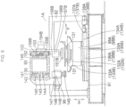
- the grinding worktable 98A includes a plurality of suction pads 131 for sucking the glass plate 2 on an upper surface thereof, a table base 132A onto which the suction pads 131 are sucked to support the suction pads 131, and a main body unit 133A for rotatably bearing and holding the table base 132A and for subjecting the table base 132A to angularly controlled rotation under NC control.
- a Y-axis moving means 134A for moving the grinding worktable 98A in the Y-axis direction includes two guide rails 136A juxtaposed on an upper surface of the base 91 along the Y-axis direction, a Y-axis moving base 135A installed on a pair of slide blocks respectively held on the guide rails 136A movably in the Y-axis direction and incorporating the main body unit 133A, a feed screw 137A connected to the Y-axis moving base 135A by means of a nut and provided between the guide rails 136A, and a Y-axis control motor 138A whose output rotating shaft is coupled to one end of the feed screw 137A.
- the grinding worktable 98A is mounted on the Y-axis moving base 135A, and is adapted to be moved in the Y-axis direction through the movement in the Y-axis direction of the Y-axis moving base 135A as the Y-axis control motor 138A is driven.
- the grinding worktable 98B includes the plurality of suction pads 131 for sucking the glass plate 2 on an upper surface thereof, a table base 132B onto which the suction pads 131 are sucked to support the suction pads 131, and a main body unit 133B for rotatably bearing and holding the table base 132B and for subjecting the table base 132B to angularly controlled rotation under NC control.
- a Y-axis moving means 134B for moving the grinding worktable 98B in the Y-axis direction includes two guide rails 136B juxtaposed on an upper surface of the base 91 along the Y-axis direction, a Y-axis moving base 135B installed on a pair of slide blocks respectively held on the guide rails 136B movably in the Y-axis direction and incorporating the main body unit 133B, a feed screw 137B connected to the Y-axis moving base 135B by means of a nut and provided between the guide rails 136B, and a Y-axis control motor 138B whose output rotating shaft is coupled to one end of the feed screw 137B.
- the grinding worktable 98B is mounted on the Y-axis moving base 135B, and is adapted to be moved in the Y-axis direction through the movement in the Y-axis direction of the Y-axis moving base 135B as the Y-axis control motor 138B is driven.
- the X-axis direction moving means 140 for moving the grinding head 99 in the X-axis direction includes a pair of position guide rails 141 mounted on a front surface 130 of the mount 93 in such a manner as to extend in the X-axis direction in correspondence with the grinding worktables 98A and 98B, an X-axis direction moving base 142 integrally fixed to a pair of slide blocks respectively held on the guide rails 141 movably in the X-axis direction, a feed screw 143 connected to the X-axis direction moving base 142 by means of a nut and provided between the guide rails 141, and an X-axis direction control motor 144 coupled to one end of the feed screw 143.
- the X-axis control motor 144 As the X-axis control motor 144 is driven, the X-axis direction moving base 142 and, hence, the grinding head 99 mounted on the X-axis direction moving base 142 by means of a bracket 147 advance alternately to the positions corresponding to the respective work coordinate systems of the grinding worktables 98A and 98B, and effect polar coordinate operation together with the grinding worktable 98A or 98B.
- a spindle motor 146 is mounted at a lower end portion of the bracket 147 via a slide unit 148 for adjusting the position in the Y-axis direction of the grinding wheel 145, and the grinding wheel 145 is fitted to an output rotating shaft of the spindle motor 146.
- the glass-plate transporting device 100 provided on a rear surface 149 of the mount 93 includes two transporting shuttles 150B and 150C; a pair of guide rails 152 juxtaposed on a rear surface of the mount 93 in such a manner as to range in the X-axis direction from above the scribing and bend-breaking position 95 of the scribe line/end cut line forming and pressing device 97 to above the discharge conveyor 129; and a rack 153 juxtaposed between the guide rails 152.
- the transporting shuttles 150B and 150C are held by the guide rails 152 movably in the X-axis direction via slide blocks and are adapted to linearly reciprocate in the X-axis direction.
- the transporting shuttle 150 has a plate bracket 158B mounted on a pair of slide blocks respectively held by the guide rails 152 movably in the X-axis direction, a traveling servo motor 154B mounted on the plate bracket 158B, and a pinion gear 155B which is fitted to an output rotating shaft of the traveling servo motor 154B and meshes with the rack 153.
- the transporting shuttle 150C has a plate bracket 158C mounted on a pair of slide blocks respectively held by the guide rails 152 movably in the X-axis direction, a traveling servo motor 154C mounted on the plate bracket 158C, and a pinion gear which is fitted to an output rotating shaft of the traveling servo motor 154C and is equivalent to the pinion gear 155B meshing with the rack 153.
- the transporting shuttles 150B and 150C are respectively adapted to reciprocatingly travel under NC control by a necessary distance in the X-axis direction.
- the transporting shuttle 150B has one glass-plate sucking and lifting device 156B mounted on the plate bracket 158B, and the transporting shuttle 150C has one glass-plate sucking and lifting device 156C mounted on the plate bracket 158C.
- the glass-plate sucking and lifting device 156B has a suction pad 151B for effecting the sucking of, and the releasing of suction of, the glass plate 2 at a lower end thereof and a lifting unit 157B to which the suction pad 151B is attached and which raises and lowers the suction pad 151B in the vertical direction H.
- the glass-plate sucking and lifting device 156C has a suction pad 151C for effecting the sucking of, and the releasing of suction of, the glass plate 2 at a lower end thereof and a lifting unit 157C to which the suction pad 151C is attached and which raises and lowers the suction pad 151C in the vertical direction H.
- the glass-plate sucking and lifting device 156B is mounted on the plate bracket 158B at the lifting unit 157B thereof, and the glass-plate sucking and lifting device 156C is mounted on the plate bracket 158C at the lifting unit 157C thereof.
- the glass-plate working apparatus 1A includes the grinding worktables 98A and 98B which undergo angularly controlled rotation independently of each other and movement in the Y-axis direction perpendicular to a transporting direction D of the glass plate 2 parallel to the X-axis direction, as well as the grinding head 99 which moves in a planar polar coordinate system alternately with the grinding worktables 98A and 98B.
- the grinding worktables 98A and 98B are arranged in series in parallel with the transporting direction D of the glass plate 2, and the grinding head 99 is moved alternately to positions corresponding to the respective grinding worktables 98A and 98B without returning to its point of origin.
- this one grinding worktable 98A undergoes y-axis movement while, under angular control, rotating the glass plate 2 sucked on the upper surface thereof and effects the grinding of peripheral edges of the glass plate 2 by moving the glass plate 2 in the polar coordinate system in cooperation with the grinding head 99, during which grinding operation the other grinding worktable 98B effects the discharging of the ground glass plate 2 by the transporting shuttle 150C and the receiving of a new glass plate 2 by the transporting shuttle 150B.
- the above-described operation is alternately repeated, and hence the grinding head 99 is adapted to proceed with the grinding of peripheral edges of the glass plates 2 on a continual basis.
Description
- The present invention relates to a glass-plate working apparatus for cutting out glass plates, such as glass plates for window glass plates of automobiles and glass plates for other usage, from unworked glass plates and for effecting grinding of peripheral edges of the cut-out glass plates.
- In addition, the present invention concerns a glass-plate working apparatus in which a scribing device and a bend-breaking and separating device for glass plates, on the one hand, and a grinding device, on the other hand, are connected via a sucking and transporting device, and glass plates which are continually cut out from the scribing device and the bend-breaking and separating device are consecutively supplied, as they are in their cut-out posture, to the grinding device, are continually subjected to grinding, and are consecutively discharged.
- Furthermore, the present invention concerns a glass-plate working apparatus in which a scribing section, a bend-breaking section, a grinding section, and a glass- plate transporting device are operated by being NC controlled.
- Such a glass-plate working apparatus is known from
Patent Documents 1 and 2.WO 2012/039075 A1 discloses a glass plate processing device being the basis for the preamble of claim 1.US 2009/0308219 A1 discloses a cutting apparatus. -
- Patent Document 1:
JP-B-6-75819 - Patent Document 2:
JP-A-8-231238 - In these known glass-plate working apparatuses, the bend-breaking and separating device and the grinding device are connected via a glass-plate transporting device, and glass plates which are continually cut out from the bend-breaking device are adapted to be consecutively supplied to the grinding device, to be continually subjected to grinding, and to be consecutively discharged.
- With such a glass-plate working apparatus, however, since one grinding worktable is provided in correspondence with the grinding head, upon each completion of the grinding of the glass plate supplied to and held on the grinding worktable, the grinding head moves away from the grinding worktable, returns to a standby point, and stops on standby. When the discharging of the glass plate from the grinding worktable and the receiving of a next glass plate thereon are completed, the grinding head advances toward the grinding worktable and starts grinding. Thus, an interruption time loss occurs on each occasion of delivery of the glass plate to and from the grinding worktable, so that production speed cannot be increased.
- Accordingly, the present invention has been devised in view of the conventional drawbacks described above, and its object is to provide a glass-plate working apparatus which is capable of increasing the production speed, of obtaining grinding with high accuracy and uniform dimensions, and of effecting the supply and delivery of the glass plates to and from the grinding worktable with high accuracy.
- The invention is defined by claim 1.
- In the above-described glass-plate working apparatus, two grinding worktables are provided in a grinding position, and the two grinding worktables are NC controlled independently of each other and are made to undergo coordinate movement under NC control together with one mutually common grinding head to effect grinding.
- For this reason, with the glass-plate working apparatus in accordance with the present invention, while one grinding worktable is grinding the glass plate while undergoing coordinate movement with the grinding head, the other grinding worktable stops at its point of origin to effect the delivery of a glass plate to and from that grinding worktable. Upon completion of the grinding of the glass plate on the one grinding worktable, the grinding head advances to the other grinding worktable to effect grinding on a continual basis. The grinding head continually effects grinding alternately, i.e., in a changing manner, with respect to the glass plates on the two grinding worktables without requiring the standby stop after returning to the standby point. For this reason, it is possible to eliminate a loss time and obtain high production capability.
- Additionally, with the glass-plate working apparatus in accordance with the present invention, since the glass plates on the two grinding worktables are ground by one grinding head, there is no variation in grinding dimensions of the glass plates on the two worktables, so that finishing becomes constant.
- Furthermore, with the glass-plate working apparatus in accordance with the present invention, since the two grinding worktables are NC controlled mutually independently of each other, it is possible to effect grinding of glass plates of dimensions and shapes which differ between the two grinding worktables.
- In addition, with the glass-plate working apparatus in accordance with the present invention, it is possible to effect the delivery of glass plates to and from the grinding worktables with high positional accuracy through cooperation between the two grinding worktables which are moved under NC control and the glass-plate transporting device which transports the glass plates similarly under NC control in a similar manner, and it is possible to effect accurate delivery in conformity with the locus of a contour line of grinding.
- In accordance with the present invention, it is possible to provide a glass-plate working apparatus which is capable of increasing the production speed, of obtaining grinding with high accuracy and uniform dimensions, and of effecting the supply and delivery of the glass plates to and from the grinding worktable with high accuracy.
-
-
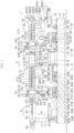
Fig. 1 is an explanatory front elevational view of an embodiment of the present invention; -
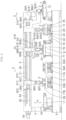
Fig. 2 is an explanatory rear view of the embodiment shown inFig. 1 ; -
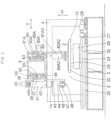
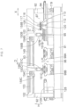
Fig. 3 is an explanatory cross-sectional view taken in the direction of arrows along line III - III ofFig. 1 ; -
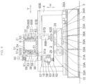
Fig. 4 is an explanatory cross-sectional view taken in the direction of arrows along line IV - IV ofFig. 1 ; -
Fig. 5 is an explanatory cross-sectional view taken in the direction of arrows along line V - V ofFig. 1 ; -
Fig. 6 is an explanatory front elevational view of another embodiment of the present invention; -
Fig. 7 is an explanatory rear view of the embodiment shown inFig. 6 ; -
Fig. 8 is an explanatory cross-sectional view taken in the direction of arrows along line VIII - VIII ofFig. 6 ; and -
Fig. 9 is an explanatory cross-sectional view taken in the direction of arrows along line IX - IX ofFig. 6 . - Hereafter, a more detailed description will be given of the preferred embodiments for carrying out the invention with reference to the drawings. It should be noted that the invention is not limited to these embodiments.
- In
Figs. 1 to 5 , a glass-plate working apparatus 1 in accordance with this embodiment has abase 3 which is installed on a floor surface, a pair of supportingcolumns 4 are respectively erected uprightly at both ends, in an X direction which is one direction in a horizontal plane (hereafter referred to as the X-axis direction), of thebase 3, and amount 6 is provided on the supportingcolumns 4 in such a manner as to bridge the supportingcolumns 4 and extend in the X-axis direction. - The glass-plate working apparatus 1, which effects processing with respect to a
glass plate 2 including the formation of a scribe line (a cut line, i.e., a bend-breaking line) on theglass plate 2, the bend-breaking of theglass plate 2 along the scribe line, and the grinding of peripheral edges of the bend-broken glass plate 2, is provided with a feeding position 7, ascribing position 8, a bend-breakingposition 9, a grindingposition 10, and adischarging position 11. - A feeding table 12 is provided in the feeding position 7. A
scribe worktable 13 and ascribe head 14 are provided in thescribing position 8. A pair of bend-breakingdevices 15 and a bend-breakingbelt conveyor 16 are provided in the bend-breakingposition 9. Twogrinding worktables head 18 are provided in thegrinding position 10. Adischarge conveyor 19 is provided in thedischarging position 11. A glass-plate transporting device 20 is provided on arear surface 21 of themount 6 along themount 6, i.e., along the X-axis direction, above the feeding table 12, thescribe worktable 13, the bend-breaking belt conveyor 16, the twogrinding worktables discharge conveyor 19 which are arranged in series along the X-axis direction. - The
scribe worktable 13 has atable body 22 for planarly supporting theglass plate 2 by an upper surface thereof, a pair oftable supporting bases 23 for fixedly supporting thetable body 22, and a Y-axis moving means 24 for moving thetable supporting bases 23 in a Y direction (hereafter referred to as the Y-axis direction) perpendicular to the X-axis direction within a horizontal plane. - The Y-axis moving means 24 includes two
guide rails 25 juxtaposed on an upper surface of thebase 3 along the Y-axis direction, a Y-axis moving base 26 installed on a pair of slide blocks respectively held on theguide rails 25 movably in the Y-axis direction, arotatable feed screw 27 connected to the Y-axis moving base 26 by means of a screw nut and provided between theguide rails 25, and a Y-axis control motor 28 coupled to one end of thefeed screw 27. Thetable body 22, which is mounted on the Y-axis moving base 26 via thetable supporting bases 23, is adapted to move in the Y-axis direction by the movement in the Y-axis direction of the Y-axis moving base 26 through the screw nut as thefeed screw 27 is rotated by the driving of the Y-axis control motor 28. - The
scribe head 14, which is moved in the X-axis direction in correspondence with the width in the X-axis direction of thetable body 22, is provided on afront surface 36 of themount 6 via an X-axis moving means 37. - The X-axis moving means 37 includes two
guide rails 49 juxtaposed on thefront surface 36 in a range in the X-axis direction exceeding the width in the X-axis direction of thetable body 22, anX-axis moving base 38 fixed to a pair of slide blocks respectively held on theguide rails 49 movably in the X-axis direction, arotatable feed screw 39 provided on thefront surface 36 between theguide rails 49, and anX-axis control motor 40 coupled to thefeed screw 39. - A
bearing unit 41 mounted on theX-axis moving base 38 has a rotatingshaft 42 with thescribe head 14 mounted at its lower end portion by means of abracket 43, so as to hold the rotatingshaft 42 rotatably with respect to theX-axis moving base 38 by means of a built-in bearing (not shown), and is provided with a rotational axis perpendicular to an X-Y plane which is a horizontal plane, i.e., the upper surface of theglass plate 2. Ascribe head body 44 is mounted at a lower end portion of the rotatingshaft 42 by means of thebracket 43, while an output rotating shaft of anangle control motor 45 is coupled to an upper end portion of the rotatingshaft 42 via a pair ofspur gears - The
scribe head 14 has, in addition to the rotatingshaft 42, thebracket 43 mounted at the lower end portion of the rotatingshaft 42 and thescribe head body 44. Thescribe head body 44 includes acutter head 47 having acutter wheel 46 at a lower end thereof and anair cylinder unit 48 which is mounted on an upper portion of thecutter head 47, vertically moves thecutter wheel 46, and imparts cutting pressure to thecutter wheel 46 during scribing. - The
angle control motor 45 is adapted to adjust the orientation of a blade edge of thecutter wheel 46 to the scribing direction by allowing thecutter wheel 46 disposed on the rotational axis of the rotatingshaft 42 to be angularly controlled about the rotational axis perpendicular to the upper surface of theglass plate 2 through thespur gears shaft 42. - Each of the two
grinding worktables glass plate 2 on the upper surface thereof, has a plurality ofsuction pads 29 for sucking theglass plate 2 on the upper surface thereof as well as a corresponding one oftable bases suction pads 29 are detachably mounted. Thetable bases - The Y-axis moving means 31A for the
table base 30A includes a pair ofguide rails 32A juxtaposed on the upper surface of thebase 3 along the Y-axis direction; a pair ofslide blocks 33A secured to thetable base 30A and held by theguide rails 32A movably in the Y-axis direction; afeed screw 34A provided rotatably on the upper surface of thebase 3 between theguide rails 32A in the X-axis direction; anut 36A secured on one side thereof to thetable base 30A and threadedly engaged with thefeed screw 34A on the other side thereof; and a Y-axis control motor 35A coupled to one end of thefeed screw 34A. Thegrinding worktable 17A having thetable base 30A is adapted to move in the Y-axis direction while being guided by theguide rails 32A as the Y-axis control motor 35A is driven. - In the same way as the Y-axis moving means 31A, the Y-axis moving means 31B for the
table base 30B includes a pair ofguide rails 32B juxtaposed on the upper surface of thebase 3 along the Y-axis direction; a pair ofslide blocks 33B held by theguide rails 32B movably in the Y-axis direction; afeed screw 34B provided rotatably on the upper surface of thebase 3 between the guide rails 32B in the X-axis direction; anut 36B secured on one side thereof to thetable base 30B and threadedly engaged with thefeed screw 34B on the other side thereof; and a Y-axis control motor 35B coupled to one end of thefeed screw 34B. The grindingworktable 17B having thetable base 30B is adapted to move in the Y-axis direction while being guided by the guide rails 32B as the Y-axis control motor 35B is driven. - The one grinding
head 18, which moves in the X-axis direction alternately in correspondence with the movement in the Y-axis direction of the grindingworktables front surface 36 of themount 6 via an X-axis moving means 50. The X-axis moving means 50 includes a pair ofguide rails 51 juxtaposed on themount 6 in a moving range in the X-axis direction corresponding to the range of disposition in the X-axis direction of the grindingworktables X-axis moving base 52 fixed integrally with a pair ofslide blocks 51a held by therespective guide rails 51 movably in the X-axis direction; afeed screw 53 connected to theX-axis moving base 52 by means of a nut and provided between the guide rails 51 in a vertical direction H; and anX-axis control motor 54 coupled to one end of thefeed screw 53. TheX-axis moving base 52 is moved in the X-axis direction with respect to the grindingworktables X-axis control motor 54 is driven. - The grinding
head 18 having a grindinghead body 58 mounted on theX-axis moving base 52 via abearing unit 55 is adapted to move in the X-axis direction alternately with respect to the grindingworktables - The bearing
unit 55 mounted on theX-axis moving base 52 rotatably holds arotating shaft 56 with an axis perpendicular to an X-Y planar coordinate system, i.e., the upper surface of theglass plate 2, by means of a bearing (not shown). The grindinghead body 58 is mounted on a lower end portion of therotating shaft 56 via abracket 57, while aspur gear 61 meshing with the spur gear fitted to an output rotating shaft of anangle control motor 60 is mounted on anupper end portion 59 thereof. - The grinding
head body 58 has aspindle motor 63 having an output rotating shaft with agrinding wheel 62 mounted thereon, as well as aslide unit 64 for adjusting in the perpendicular X-Y directions the position of thespindle motor 63 and, hence, the position of the grinding operation portion of thegrinding wheel 62 with respect to theglass plate 2. The grindinghead body 58 is adapted to effect the grinding of peripheral edges of theglass plate 2 constantly at a fixed angle with the grindingwheel 62 by positioning the grinding operation portion of thegrinding wheel 62 on the rotational axis of therotating shaft 56, by angularly controlling the rotatingshaft 56 by means of theangle control motor 60, and by causing the grindingwheel 62 to oscillate about the grinding operation portion in correspondence with the peripheral configuration of theglass plate 2 which changes. - The bend-breaking
position 9 has the bend-breakingbelt conveyor 16 on which theglass plate 2 with the scribe line formed thereon in thescribing position 8 is placed and the two bend-breakingdevices 15 for bend-breaking theglass plate 2 placed on the bend-breakingbelt conveyor 16. - Each of the bend-breaking
devices 15 has anend cutter unit 70, apress unit 71, and a moving means 72 for holding theend cutter unit 70 and thepress unit 71 and moving them along the upper surface of theglass plate 2. - Each moving means 72 has a Y-
axis moving device 73 for holding theend cutter unit 70 and thepress unit 71 and moving them in the Y-axis direction under NC control, as well as anX-axis moving device 74 for holding the Y-axis moving device 73 and moving the same in the X-axis direction. OneX-axis moving device 74 is mounted on themount 6 by means of abracket 76, and the other X-axis moving means 74 is mounted on anupright body 75, erected on thebase 3, by means of abracket 76. - The bend-breaking
belt conveyor 16 has aconveyor belt 77, a supporting plate/frame 78 which supports theconveyor belt 77 from inside in a planar shape and is supported on thebase 3, and adrive unit 79 for causing theconveyor belt 77 to circulatingly travel. - In the bend-breaking
position 9, theglass plate 2 with the scribe line formed thereon in thescribing position 8 is placed on the bend-breakingbelt conveyor 16 by suction pads 82A of a transportingshuttle 81A corresponding to thescribing position 8. - The transporting
shuttle 81A which placed on the bend-breakingbelt conveyor 16 theglass plate 2 with the scribe line formed thereon returns to thescribing position 8, and, in turn,suction pads 82B of a transportingshuttle 81B which returned to the bend-breakingposition 9 are lowered, whereupon theglass plate 2 placed on the bend-breakingbelt conveyor 16 by the transportingshuttle 81A is suckingly held and fixed by thesuction pads 82B of the transportingshuttle 81B. Theend cutter unit 70 of each bend-breakingdevice 15 is sequentially moved to necessary locations with respect to this fixedglass plate 2, and an end cut line is formed on theglass plate 2 by eachend cutter unit 70. Subsequently, eachpress unit 71 is sequentially moved to necessary locations, and theglass plate 2 with the end cut lines formed thereon is pressed by eachpress unit 71 to bend-break and separate unnecessary portions. Theglass plate 2 from which the unnecessary portions have been separated is sucked and lifted by thesuction pads 82B of the corresponding transportingshuttle 81B in the bend-breakingposition 9, and is, in this state, transported to the grindingworktable belt conveyor 16 is actuated to discharge to an outside 200 the bend-broken cullets consisting of the unnecessary portions. - The glass-
plate transporting device 20 includes a pair ofguide rails 83 laid on therear surface 21 of themount 6 in such a manner as to range from above the feeding table 12 to above thedischarge conveyor 19; three transportingshuttles guide rails 83 movably in the X-axis direction via slide blocks and linearly reciprocate in the X-axis direction while being guided by the guide rails 83; and arack 84 provided between the guide rails 83 in the vertical direction H in juxtaposition thereto and used in common for the transportingshuttles - The transporting
shuttle 81A has abracket 90A, a travelingmotor 85A mounted on thebracket 90A, and a pair of glass-plate sucking and lifting devices 87A1 and 87A2; the transportingshuttle 81B has abracket 90B, a travelingmotor 85B mounted on thebracket 90B, and a glass-plate sucking and liftingdevices 87B; and the transportingshuttle 81C has abracket 90C, a travelingmotor 85C mounted on thebracket 90C, and a glass-plate sucking andlifting devices 87C. Each of thebrackets guide rails 83 via slide blocks movably in the X-axis direction. - A
pinion gear 86A, apinion gear 86B, and apinion gear 86C are respectively mounted on an output rotating shaft of the travelingmotor 85A, an output rotating shaft of the travelingmotor 85B, and an output rotating shaft of the travelingmotor 85C in such a manner as to respectively mesh with thegear rack 84. - The transporting shuttles 81A, 81B, and 81C are respectively adapted to reciprocatingly travel in the X-axis direction by necessary distances independently of each other as the
respective traveling motors - The glass-plate sucking and lifting device 87A1 has a plurality of suction pads 82A1 for effecting the sucking of, and the releasing of suction of, the
glass plate 2 and a lifting unit 89A1 to which the suction pads 82A1 are attached and which raises and lowers the suction pads 82A1. The glass-plate sucking and lifting device 87A2 has a plurality of suction pads 82A2 for effecting the sucking of, and the releasing of suction of, theglass plate 2 and a lifting unit 89A2 to which the suction pads 82A2 are attached and which raises and lowers the suction pads 82A2. The glass-plate sucking and liftingdevice 87B has a plurality ofsuction pads 82B for effecting the sucking of, and the releasing of suction of, theglass plate 2 and alifting unit 89B to which thesuction pads 82B are attached and which raises and lowers thesuction pads 82B. The glass-plate sucking and liftingdevice 87C has a plurality ofsuction pads 82C for effecting the sucking of, and the releasing of suction of, theglass plate 2 and alifting unit 89C to which thesuction pads 82C are attached and which raises and lowers thesuction pads 82C. - The transporting
shuttle 81A having the two glass-plate sucking and lifting devices 87A1 and 87A2 is adapted to repeat reciprocating motion so as to effect replacement transport of theglass plate 2 from the feeding table 12 to thescribe worktable 13 and from thescribe worktable 13 to the bend-breakingbelt conveyor 16, such that, as its travelingmotor 85A is operated, at an end of its return movement in the X-axis direction, the transportingshuttle 81A causes the glass-plate sucking and lifting device 87A1 to be positioned above the feeding table 12 and the glass-plate sucking and lifting device 87A2 to be positioned above thescribe worktable 13 and, at an end of its forward movement, the transportingshuttle 81A causes the glass-plate sucking and lifting device 87A2 to be positioned above the bend-breakingbelt conveyor 16 and the glass-plate sucking and lifting device 87A1 to be positioned above thescribe worktable 13. - As its traveling
motor 85B is operated, the transportingshuttle 81B is moved reciprocatingly between above the bend-breakingbelt conveyor 16 and above an alternate one of the grindingworktables glass plate 2 bend-broken on the bend-breakingbelt conveyor 16 to be transported alternately to the grindingworktable 17A and the grindingworktable 17B. - As its traveling
motor 85C is operated, the transportingshuttle 81C alternately carries out theground glass plates 2 on the grindingworktables discharge conveyor 19. - In the glass-plate working apparatus 1, concurrently with the start of its operation, the glass-
plate transporting device 20 is operated, and the suction pads 82A1 are lowered at the feeding table 12 to suck and lift theglass plate 2, i.e., an unworked glass plate on the feeding table 12, and the transportingshuttle 81A is moved forwardly. When the suction pads 82A1 sucking theglass plate 2 reach above thescribe worktable 13, the suction pads 82A1 are lowered and release the suction of theglass plate 2 to place theglass plate 2 onto thescribe worktable 13. The emptied suction pads 82A1 are raised and return again to above the feeding table 12 by a returning movement of the transportingshuttle 81A. In turn, simultaneously as the suction pads 82A2 corresponding to thescribe worktable 13 are returned to above thescribe worktable 13, thescribe head 14 and thescribe worktable 13 are moved in the X-Y coordinate plane, and a scribe line is formed on theglass plate 2 by thecutter wheel 46. Upon completion of the formation of this scribe line, thescribe head 14 and thescribe worktable 13 are returned to their points of origin. Next, the suction pads 82A2 which returned to above thescribe worktable 13 are lowered to suck and lift theglass plate 2 with the scribe line formed thereon. Theglass plate 2 sucked and lifted by the suction pads 82A2 is transported toward the bend-breakingposition 9 by the forward movement of the transportingshuttle 81A, and when the suction pads 82A2 sucking theglass plate 2 with the scribe line formed thereon reach the bend-breakingposition 9, the suction pads 82A2 are lowered to release the suction of theunworked plate glass 2 with the scribe line formed thereon and place on the bend-breakingbelt conveyor 16 theunworked plate glass 2 with the scribe line formed thereon, whereupon, the suction pads 82A2 are returned to above thescribe worktable 13. In turn, the transportingshuttle 81B corresponding to the bend-breakingposition 9 is returned to the bend-breakingposition 9 and lowers thesuction pads 82B immediately, and theglass plate 2 with the scribe line formed thereon and placed on the bend-breakingbelt conveyor 16 is sucked by thesuction pads 82B and is pressed immovably against the bend-breakingbelt conveyor 16. In this state, the respective bend-breakingdevices 15 are operated, and eachend cutter unit 70 and eachpress unit 71 are moved above theglass plate 2 with the scribe line formed thereon to effect end cutting and then pressing operation at necessary positions, thereby bend-breaking and separating unnecessary portions in the outer region along the scribe line and fabricating the cut-outglass plate 2. After the fabrication, thesuction pads 82B which are continuing to suck the cut-outglass plate 2 are raised as they are, and lift the cut-outglass plate 2. In the state in which theglass plate 2 is thus being sucked and lifted by thesuction pads 82B, the transportingshuttle 81B starts forward movement toward the grindingposition 10, during which time, in the grindingposition 10, theglass plate 2 being sucked by thesuction pads 29 onto one grindingworktable 17A of the two grindingworktables worktable 17A and the grindinghead 18. Meanwhile, the other grindingworktable 17B is returned to its point of origin, and in the state in which the processedglass plate 2 is being carried out by the transportingshuttle 81C, thesuction pads 82B suck the cut-outglass plate 2 on theconveyor belt 77, are moved to above the grindingworktable 17B by the transportingshuttle 81B, and are lowered toward the grindingworktable 17B, and thesuction pads 82B are released from sucking on the grindingworktable 17B to carry in and place that cut-outglass plate 2 onto the grindingworktable 17B. At the same time, the grindingworktable 17B sucks and fixes the received cut-outglass plate 2 by means of thesuction pads 29 and advances toward the grinding area. Simultaneously with the completion of grinding on the grindingworktable 17A engaged in grinding operation in advance, the grindinghead 18 advances to the grindingworktable 17B and undergoes X-Y coordinate movement together with the grindingworktable 17B to effect the grinding of peripheral edges of the newly cut-outglass plate 2 on the grindingworktable 17B. - In the above-described manner, with the glass-plate working apparatus 1, the grinding
worktables head 18 and alternately repeat the operation in which while one grindingworktable glass plate 2, is effecting the grinding of theglass plate 2 by the grindinghead 18, the other grindingworktable glass plate 2 and the receiving of theglass plate 2, and the grindinghead 18 is thus adapted to effect the grinding of peripheral edges of theglass plates 2 on a continual basis. - A glass-
plate working apparatus 1A in accordance with this embodiment shown inFigs. 6 to 9 also has a base 91 which is installed on the floor surface, and a pair of supportingcolumns 92 are respectively erected uprightly at both ends in the X-axis direction of thebase 91. Amount 93 is installed on the supportingcolumns 92 in such a manner as to bridge the supportingcolumns 92 and extend in the X-axis direction. The glass-plate working apparatus 90 is provided with afeeding position 94, a scribing and bend-breakingposition 95, a grindingposition 96, and a dischargingposition 128. In the scribing and bend-breakingposition 95, the formation of a scribe line on theglass plate 2 and the bend-breaking and separation of theglass plate 2 with the scribe line formed thereon (fabrication of the cut-out glass plate 2) are performed with theglass plate 2 fixed at the same position. - A scribe line/end cut line forming and
pressing device 97 is provided in thefeeding position 94 and the scribing and bend-breakingposition 95; two grindingworktables head 99 are provided in the grindingposition 96; and adischarge conveyor 129 is provided in the dischargingposition 128. - The scribe line/end cut line forming and
pressing device 97, the grindingworktables discharge conveyor 129 are arranged in series along themount 93, i.e., along the X-axis direction, and at necessary intervals. A glass-plate transporting device 100 is provided in such a manner as to extend linearly above the scribe line/end cut line forming andpressing device 97, the grindingworktables discharge conveyor 129. - The scribe line/end cut line forming and
pressing device 97 includes a belt conveyor table 102 for planarly supporting and transporting theglass plate 2 and stopping theglass plate 2 at a predetermined position, as well as ascribe head 105 and a bend-breakingdevice 106 which move in the X-Y planar coordinate system in parallel with the upper surface of the belt conveyor table 102. - The belt conveyor table 102 includes a
wide conveyor belt 103, a supportingbase 104 for planarly supporting theconveyor belt 103 from the underside, and anNC control motor 119 for causing theconveyor belt 103 to travel under NC control. - The
feeding position 94 and the scribing and bend-breakingposition 95 are respectively formed on one side in the X-axis direction and on the other side in the X-axis direction with a central region in the X-axis direction of the upper surface of theconveyor belt 103 interposed therebetween. - A pair of
guide rails 108 are provided on amain body frame 107 along the X-axis direction on each opposite side in the Y-axis direction of the belt conveyor table 102 mounted along the X-axis direction on the inner side of themain body frame 107, and a pair of slide blocks 109 are held by therespective guide rails 108 movably in the X-axis direction. Above the belt conveyor table 102, a travelingframe 110 is installed on the slide blocks 109 by means of a pair ofbrackets 120 at both ends in the Y-axis direction which is a direction perpendicular to the X-axis direction in the horizontal plane. - The traveling
frame 110, which is supported by the slide blocks 109 respectively fitted over theguide rails 108 movably in the X-axis direction, is movable in the X-axis direction by being guided by the guide rails 108. On each opposite side of the belt conveyor table 102, arack 111 extending in the X-axis direction in parallel with theguide rail 108 is provided on each side of themain body frame 107. - A
pinion gear 112 meshing with thecorresponding rack 111 is rotatably mounted on eachbracket 120 mounted on each opposite side in the Y-axis direction of the travelingframe 110. - A
shaft 121 is rotatably fitted in the travelingframe 110 in such a manner as to penetrate therespective brackets 120. Each opposite end portion in the Y-axis direction of theshaft 121 is coupled to thecorresponding pinion gear 112 via a pulley and a belt, and an output rotating shaft of anX-axis servo motor 113 is connected to one end portion of theshaft 121. The travelingframe 110 is moved in the X-axis direction by the rotation of therespective pinion gear 112 through the pulley and the belt due to the operation of theX-axis servo motor 113 and by the meshing between the respective ones of thepinion gear 112 and therack 111. - On the traveling
frame 110, a pair ofguide rails 114 and a rack 115 along theguide rails 114 are juxtaposed along the Y-axis direction, respectively. Abracket 116 is mounted on slide blocks held by theguide rails 114 movably in the Y-axis direction, and thebracket 116 is movable in the Y-axis direction by being guided by the pair of guide rails 114. A Y-axis servo motor 117 is mounted on thebracket 116, and a pinion gear 118 meshing with the rack 115 is mounted on an output rotating shaft of the Y-axis servo motor 117. Thebracket 116 is moved in the Y-axis direction by being guided by the pair ofguide rails 114 as the Y-axis servo motor 117 is operated. - The
scribe head 105 and the bend-breakingdevice 106 are juxtaposed on a front surface of thebracket 116. Thescribe head 105 and the bend-breakingdevice 106 integrally undergoes X-Y planar coordinate movement by the movement in the X-axis direction of the travelingframe 110 and the movement in the Y-axis direction of thebracket 116 above the belt conveyor table 102. - The
scribe head 105 includes acutter head 122 having acutter wheel 124 at a lower end of therotating shaft 125; anair cylinder unit 123 which is mounted on an upper portion of arotating shaft 125, vertically moves thecutter wheel 46 via therotating shaft 125, and imparts cutting pressure to thecutter wheel 124 via therotating shaft 125 during scribing; and aangle control motor 201 for adjusting the orientation of a blade edge of thecutter wheel 124 to the scribing direction and the end cutting direction by allowing therotating shaft 125 with thecutter wheel 124 mounted thereon to be angularly controlled about the rotational axis of therotating shaft 125. An output rotating shaft of theangle control motor 201 is coupled to therotating shaft 125 via a pair of mutually meshing spur gears. The bend-breakingdevice 106 applies pressing pressure to necessary portions of theglass plate 2 with the end cut line formed thereon by apusher 127 via arod 139, which is movable in the vertical direction H, by means of hydraulic or pneumatic pressure of a hydraulic orpneumatic cylinder 126, to thereby bend-break unnecessary portions and fabricating the cut-outglass plate 2. - In the scribing and bend-breaking
position 95, thescribe head 105 and the bend-breakingdevice 106 are integrally moved under NC control by using thescribe head 105 as a reference on the basis of scribe forming information stored in advance. First, thescribe head 105 is operated to form a scribe line on theglass plate 2, and subsequently to the end cut line formation after the formation of the scribe line thescribe head 105 and the bend-breakingdevice 106 are integrally moved under NC control by using the bend-breakingdevice 106 as a reference on the basis of bend-breaking information stored in advance. The bend-breakingdevice 106 is moved to each of a plurality of positions requiring pressing, the bend-breakingdevice 106 is operated at each of these positions to sequentially apply pressing pressure to theglass plate 2, thereby bend-breaking and separating unnecessary regions from theglass plate 2 and fabricating the cut-outglass plate 2. After the fabrication of the cut-outglass plate 2, a transportingshuttle 150B returns to above the cut-outglass plate 2 and lowers asuction pad 151B to suck and lift the cut-outglass plate 2, and transports it to the grindingposition 96. - In the grinding
position 96, the grindinghead 99 provided on themount 93 via an X-axis direction moving means 140 moves alternately to positions corresponding to the grindingworktables worktables - Each of the grinding
worktables glass plate 2 on the upper surface thereof, moves in the Y-axis direction while subjecting theglass plate 2 to angularly controlled rotation under NC control, and undergoes polar coordinate operation together with the grindinghead 99 which is fixed, to thereby effect the polar coordinate grinding of peripheral edges of theglass plate 2 by agrinding wheel 145 of the grindinghead 99. - Namely, in the grinding
position 96, work coordinate systems are respectively provided for the respective positions of the grindingworktables head 99 is adapted to move along the X-axis direction alternately to the corresponding positions of the respective work coordinate systems and stop thereat. In the work coordinate system where the grindinghead 99 stopped, theglass plate 2 is adapted to undergo polar coordinate operation with respect to the grindinghead 99 which stopped, by the angular controlled rotation of theglass plate 2 by the grindingworktable glass plate 2 by the grindingworktable worktables - The grinding worktable 98A includes a plurality of
suction pads 131 for sucking theglass plate 2 on an upper surface thereof, atable base 132A onto which thesuction pads 131 are sucked to support thesuction pads 131, and amain body unit 133A for rotatably bearing and holding thetable base 132A and for subjecting thetable base 132A to angularly controlled rotation under NC control. - A Y-axis moving means 134A for moving the grinding
worktable 98A in the Y-axis direction includes twoguide rails 136A juxtaposed on an upper surface of thebase 91 along the Y-axis direction, a Y-axis moving base 135A installed on a pair of slide blocks respectively held on theguide rails 136A movably in the Y-axis direction and incorporating themain body unit 133A, afeed screw 137A connected to the Y-axis moving base 135A by means of a nut and provided between theguide rails 136A, and a Y-axis control motor 138A whose output rotating shaft is coupled to one end of thefeed screw 137A. The grindingworktable 98A is mounted on the Y-axis moving base 135A, and is adapted to be moved in the Y-axis direction through the movement in the Y-axis direction of the Y-axis moving base 135A as the Y-axis control motor 138A is driven. - The grinding
worktable 98B includes the plurality ofsuction pads 131 for sucking theglass plate 2 on an upper surface thereof, atable base 132B onto which thesuction pads 131 are sucked to support thesuction pads 131, and amain body unit 133B for rotatably bearing and holding thetable base 132B and for subjecting thetable base 132B to angularly controlled rotation under NC control. - A Y-axis moving means 134B for moving the grinding
worktable 98B in the Y-axis direction includes twoguide rails 136B juxtaposed on an upper surface of thebase 91 along the Y-axis direction, a Y-axis moving base 135B installed on a pair of slide blocks respectively held on theguide rails 136B movably in the Y-axis direction and incorporating themain body unit 133B, afeed screw 137B connected to the Y-axis moving base 135B by means of a nut and provided between the guide rails 136B, and a Y-axis control motor 138B whose output rotating shaft is coupled to one end of thefeed screw 137B. The grindingworktable 98B is mounted on the Y-axis moving base 135B, and is adapted to be moved in the Y-axis direction through the movement in the Y-axis direction of the Y-axis moving base 135B as the Y-axis control motor 138B is driven. - The X-axis direction moving means 140 for moving the grinding
head 99 in the X-axis direction includes a pair of position guide rails 141 mounted on afront surface 130 of themount 93 in such a manner as to extend in the X-axis direction in correspondence with the grindingworktables direction moving base 142 integrally fixed to a pair of slide blocks respectively held on theguide rails 141 movably in the X-axis direction, afeed screw 143 connected to the X-axisdirection moving base 142 by means of a nut and provided between theguide rails 141, and an X-axisdirection control motor 144 coupled to one end of thefeed screw 143. - As the
X-axis control motor 144 is driven, the X-axisdirection moving base 142 and, hence, the grindinghead 99 mounted on the X-axisdirection moving base 142 by means of abracket 147 advance alternately to the positions corresponding to the respective work coordinate systems of the grindingworktables worktable - A
spindle motor 146 is mounted at a lower end portion of thebracket 147 via aslide unit 148 for adjusting the position in the Y-axis direction of thegrinding wheel 145, and thegrinding wheel 145 is fitted to an output rotating shaft of thespindle motor 146. - The glass-
plate transporting device 100 provided on arear surface 149 of themount 93 includes two transportingshuttles guide rails 152 juxtaposed on a rear surface of themount 93 in such a manner as to range in the X-axis direction from above the scribing and bend-breakingposition 95 of the scribe line/end cut line forming andpressing device 97 to above thedischarge conveyor 129; and arack 153 juxtaposed between the guide rails 152. The transporting shuttles 150B and 150C are held by theguide rails 152 movably in the X-axis direction via slide blocks and are adapted to linearly reciprocate in the X-axis direction. - The transporting shuttle 150 has a
plate bracket 158B mounted on a pair of slide blocks respectively held by theguide rails 152 movably in the X-axis direction, a travelingservo motor 154B mounted on theplate bracket 158B, and apinion gear 155B which is fitted to an output rotating shaft of the travelingservo motor 154B and meshes with therack 153. - The transporting
shuttle 150C has aplate bracket 158C mounted on a pair of slide blocks respectively held by theguide rails 152 movably in the X-axis direction, a travelingservo motor 154C mounted on theplate bracket 158C, and a pinion gear which is fitted to an output rotating shaft of the travelingservo motor 154C and is equivalent to thepinion gear 155B meshing with therack 153. - As the traveling
servo motors shuttles shuttles - The transporting
shuttle 150B has one glass-plate sucking and liftingdevice 156B mounted on theplate bracket 158B, and the transportingshuttle 150C has one glass-plate sucking and liftingdevice 156C mounted on theplate bracket 158C. The glass-plate sucking and liftingdevice 156B has asuction pad 151B for effecting the sucking of, and the releasing of suction of, theglass plate 2 at a lower end thereof and alifting unit 157B to which thesuction pad 151B is attached and which raises and lowers thesuction pad 151B in the vertical direction H. The glass-plate sucking and liftingdevice 156C has asuction pad 151C for effecting the sucking of, and the releasing of suction of, theglass plate 2 at a lower end thereof and alifting unit 157C to which thesuction pad 151C is attached and which raises and lowers thesuction pad 151C in the vertical direction H. The glass-plate sucking and liftingdevice 156B is mounted on theplate bracket 158B at thelifting unit 157B thereof, and the glass-plate sucking and liftingdevice 156C is mounted on theplate bracket 158C at thelifting unit 157C thereof. - The glass-
plate working apparatus 1A includes the grindingworktables glass plate 2 parallel to the X-axis direction, as well as the grindinghead 99 which moves in a planar polar coordinate system alternately with the grindingworktables worktables glass plate 2, and the grindinghead 99 is moved alternately to positions corresponding to therespective grinding worktables head 99 is positioned with respect to one grindingworktable 98A, this one grindingworktable 98A undergoes y-axis movement while, under angular control, rotating theglass plate 2 sucked on the upper surface thereof and effects the grinding of peripheral edges of theglass plate 2 by moving theglass plate 2 in the polar coordinate system in cooperation with the grindinghead 99, during which grinding operation the other grindingworktable 98B effects the discharging of theground glass plate 2 by the transportingshuttle 150C and the receiving of anew glass plate 2 by the transportingshuttle 150B. Thus, with the glass-plate working apparatus 1A, the above-described operation is alternately repeated, and hence the grindinghead 99 is adapted to proceed with the grinding of peripheral edges of theglass plates 2 on a continual basis. -
- 1:
- glass-plate working apparatus
- 2:
- glass plate
- 3:
- base
- 7:
- feeding position
- 8:
- scribing position
- 9:
- bend-breaking position
- 10:
- grinding position
- 17A, 17B:
- grinding worktable
- 18:
- grinding head
Claims (1)
- A glass-plate working apparatus (1) comprising a grinding head (18), which is adapted to move in an X-axis direction which is the transporting direction of the glass plate, characterized by comprising:two grinding worktables (17A, 17B) which undergo NC controlled movement or angularly controlled rotation independently of each other; andwherein the grinding head (18) undergoes NC controlled movement in correspondence with the two grinding worktables (17A, 17B),wherein the two grinding worktables (17A, 17B) alternately move in a planar coordinate system in cooperation with the grinding head (18) and alternately repeat operation in which while one of the grinding worktables (17A), while holding a bend-broken glass plate, is effecting grinding of peripheral edges of the bend-broken glass plate by the grinding head (18), another one of the grinding worktables (17B) effects an operation of discharging a ground glass plate and receiving a next glass plate, to thereby allow the grinding head (18) to effect grinding of consecutively received glass plates on a continual basis,wherein either:(a) said two grinding worktables (17A, 17B) move independently of each other in a Y-axis direction perpendicular to a direction of transporting the glass plate and are arranged in the transporting direction of the glass plate; and
wherein said grinding head (18) is adapted to move in an X-Y planar coordinate system in a changing manner with the grinding worktable holding the glass plate and effect grinding on a continual basis;
or(b) said two grinding worktables (17A, 17B) are adapted to undergo angularly controlled rotation independently of each other and move in a Y-axis direction perpendicular to a transporting direction of the glass plate; and said grinding head (18) is adapted to move in a planar coordinate system alternately in cooperation with each of the two grinding worktables (17A, 17B),
the two grinding worktables being arranged in series in the transporting direction of the glass plate.
Applications Claiming Priority (2)
| Application Number | Priority Date | Filing Date | Title |
|---|---|---|---|
| JP2015149057 | 2015-07-28 | ||
| PCT/JP2016/002349 WO2017017870A1 (en) | 2015-07-28 | 2016-05-13 | Glass plate processing device |
Publications (4)
| Publication Number | Publication Date |
|---|---|
| EP3330236A1 EP3330236A1 (en) | 2018-06-06 |
| EP3330236A4 EP3330236A4 (en) | 2019-08-14 |
| EP3330236B1 true EP3330236B1 (en) | 2023-11-22 |
| EP3330236C0 EP3330236C0 (en) | 2023-11-22 |
Family
ID=57884651
Family Applications (1)
| Application Number | Title | Priority Date | Filing Date |
|---|---|---|---|
| EP16829979.0A Active EP3330236B1 (en) | 2015-07-28 | 2016-05-13 | Glass-plate working apparatus |
Country Status (6)
| Country | Link |
|---|---|
| US (1) | US10357864B2 (en) |
| EP (1) | EP3330236B1 (en) |
| JP (2) | JP6195032B2 (en) |
| CN (2) | CN111251117A (en) |
| TW (2) | TWI656083B (en) |
| WO (1) | WO2017017870A1 (en) |
Families Citing this family (10)
| Publication number | Priority date | Publication date | Assignee | Title |
|---|---|---|---|---|
| KR102080233B1 (en) * | 2015-09-01 | 2020-02-21 | 반도키코 가부시키가이샤 | Glass sheet processing equipment |
| MX2018004723A (en) * | 2015-10-23 | 2018-07-06 | Bando Kiko Co | Glass plate machining apparatus. |
| JP6194983B2 (en) * | 2016-05-13 | 2017-09-13 | 坂東機工株式会社 | Glass plate processing equipment |
| CN108067971A (en) * | 2017-12-14 | 2018-05-25 | 浙江理工大学 | Glass edge continuous grinding method |
| CN108372448B (en) * | 2018-03-16 | 2023-09-08 | 青岛普力捷自动化科技有限公司 | Automatic edging machine |
| USD870165S1 (en) | 2018-04-03 | 2019-12-17 | Michael Hacikyan | Glass grinding apparatus |
| CN108383368A (en) * | 2018-05-08 | 2018-08-10 | 蚌埠市昆宇机械加工厂 | A kind of glass manufacture cutting device for processing |
| TW202204276A (en) * | 2018-11-26 | 2022-02-01 | 日商坂東機工股份有限公司 | Glass plate working apparatus |
| JP2023043232A (en) * | 2021-09-16 | 2023-03-29 | 坂東機工株式会社 | Glass plate machining system |
| CN115072982B (en) * | 2022-05-05 | 2023-09-12 | 中建材(内江)玻璃高新技术有限公司 | Bending device for toughened glass |
Family Cites Families (18)
| Publication number | Priority date | Publication date | Assignee | Title |
|---|---|---|---|---|
| JPH0675819B2 (en) * | 1988-08-13 | 1994-09-28 | 坂東機工株式会社 | Glass plate processing machine |
| EP0465675B1 (en) * | 1990-01-31 | 1996-09-11 | Bando Kiko Co. Ltd. | Machine for working glass plate |
| JPH0675819A (en) | 1992-08-27 | 1994-03-18 | Mitsubishi Electric Corp | Microprocessor |
| JPH08231238A (en) * | 1995-02-24 | 1996-09-10 | Bando Kiko Kk | Working device for glass plate |
| JP2000237939A (en) * | 1999-02-17 | 2000-09-05 | Sumitomo Heavy Ind Ltd | Tandem table type rotary grinder |
| JP4433555B2 (en) * | 2000-03-23 | 2010-03-17 | 坂東機工株式会社 | Glass plate processing method and apparatus |
| CN101332578B (en) * | 2007-06-28 | 2010-10-06 | 坂东机工株式会社 | Grinding device of glass plate |
| JP5385519B2 (en) | 2007-08-24 | 2014-01-08 | 株式会社東京精密 | Cleaning device with chamfering function |
| JP2009160725A (en) | 2008-01-07 | 2009-07-23 | Sfa Engineering Corp | Chamfering tool for flat panel display |
| US8297892B2 (en) * | 2008-06-17 | 2012-10-30 | Sony Corportion | Cutting apparatus |
| JP5549683B2 (en) * | 2010-01-27 | 2014-07-16 | 坂東機工株式会社 | Glass plate processing equipment |
| JP5561360B2 (en) | 2010-03-29 | 2014-07-30 | 坂東機工株式会社 | Glass plate processing equipment |
| JP2012001384A (en) | 2010-06-16 | 2012-01-05 | Hallys Corp | Method and apparatus for processing glass plate |
| JP5617925B2 (en) * | 2010-09-22 | 2014-11-05 | 坂東機工株式会社 | Automatic measurement and correction of glass plate dimensions |
| CN203330839U (en) * | 2013-07-08 | 2013-12-11 | 厦门万久科技有限公司 | Five-axis special-shaped curved surface grinder |
| CN203993429U (en) * | 2014-07-22 | 2014-12-10 | 陆如东 | Special-shaped glass numerical control beveler |
| CN104526028A (en) * | 2015-01-16 | 2015-04-22 | 东莞上善精机有限公司 | Double-workbench application based intelligent machining center |
| JP6194983B2 (en) * | 2016-05-13 | 2017-09-13 | 坂東機工株式会社 | Glass plate processing equipment |
-
2016
- 2016-05-13 CN CN202010142911.3A patent/CN111251117A/en active Pending
- 2016-05-13 US US15/553,025 patent/US10357864B2/en active Active
- 2016-05-13 CN CN201680011905.6A patent/CN107250077B/en active Active
- 2016-05-13 JP JP2017503026A patent/JP6195032B2/en active Active
- 2016-05-13 EP EP16829979.0A patent/EP3330236B1/en active Active
- 2016-05-13 WO PCT/JP2016/002349 patent/WO2017017870A1/en active Application Filing
- 2016-07-05 TW TW106141253A patent/TWI656083B/en active
- 2016-07-05 TW TW105121271A patent/TWI613135B/en active
-
2017
- 2017-07-28 JP JP2017146242A patent/JP6999153B2/en active Active
Also Published As
| Publication number | Publication date |
|---|---|
| EP3330236C0 (en) | 2023-11-22 |
| JP2017218375A (en) | 2017-12-14 |
| TW201806841A (en) | 2018-03-01 |
| CN111251117A (en) | 2020-06-09 |
| EP3330236A4 (en) | 2019-08-14 |
| TW201708086A (en) | 2017-03-01 |
| TWI613135B (en) | 2018-02-01 |
| JPWO2017017870A1 (en) | 2017-07-27 |
| US10357864B2 (en) | 2019-07-23 |
| WO2017017870A1 (en) | 2017-02-02 |
| EP3330236A1 (en) | 2018-06-06 |
| JP6195032B2 (en) | 2017-09-13 |
| JP6999153B2 (en) | 2022-01-18 |
| CN107250077B (en) | 2020-03-20 |
| CN107250077A (en) | 2017-10-13 |
| US20180036856A1 (en) | 2018-02-08 |
| TWI656083B (en) | 2019-04-11 |
Similar Documents
| Publication | Publication Date | Title |
|---|---|---|
| EP3330236B1 (en) | Glass-plate working apparatus | |
| JP6893653B2 (en) | Glass plate processing equipment | |
| JP6195036B2 (en) | Glass plate processing equipment | |
| US10800697B2 (en) | Glass-plate working apparatus | |
| JP6194983B2 (en) | Glass plate processing equipment | |
| JP2017031041A5 (en) | ||
| JP6308312B2 (en) | Glass plate processing equipment | |
| JP6643731B2 (en) | Glass plate processing equipment | |
| JP6856499B2 (en) | Glass plate processing equipment | |
| JP6708826B2 (en) | Glass plate processing equipment |
Legal Events
| Date | Code | Title | Description |
|---|---|---|---|
| STAA | Information on the status of an ep patent application or granted ep patent |
Free format text: STATUS: THE INTERNATIONAL PUBLICATION HAS BEEN MADE |
|
| PUAI | Public reference made under article 153(3) epc to a published international application that has entered the european phase |
Free format text: ORIGINAL CODE: 0009012 |
|
| STAA | Information on the status of an ep patent application or granted ep patent |
Free format text: STATUS: REQUEST FOR EXAMINATION WAS MADE |
|
| 17P | Request for examination filed |
Effective date: 20170710 |
|
| AK | Designated contracting states |
Kind code of ref document: A1 Designated state(s): AL AT BE BG CH CY CZ DE DK EE ES FI FR GB GR HR HU IE IS IT LI LT LU LV MC MK MT NL NO PL PT RO RS SE SI SK SM TR |
|
| AX | Request for extension of the european patent |
Extension state: BA ME |
|
| DAV | Request for validation of the european patent (deleted) | ||
| DAX | Request for extension of the european patent (deleted) | ||
| A4 | Supplementary search report drawn up and despatched |
Effective date: 20190716 |
|
| RIC1 | Information provided on ipc code assigned before grant |
Ipc: C03C 19/00 20060101AFI20190710BHEP Ipc: B24B 41/06 20120101ALI20190710BHEP Ipc: B24B 9/10 20060101ALI20190710BHEP |
|
| STAA | Information on the status of an ep patent application or granted ep patent |
Free format text: STATUS: EXAMINATION IS IN PROGRESS |
|
| 17Q | First examination report despatched |
Effective date: 20220104 |
|
| GRAJ | Information related to disapproval of communication of intention to grant by the applicant or resumption of examination proceedings by the epo deleted |
Free format text: ORIGINAL CODE: EPIDOSDIGR1 |
|
| GRAP | Despatch of communication of intention to grant a patent |
Free format text: ORIGINAL CODE: EPIDOSNIGR1 |
|
| GRAP | Despatch of communication of intention to grant a patent |
Free format text: ORIGINAL CODE: EPIDOSNIGR1 |
|
| STAA | Information on the status of an ep patent application or granted ep patent |
Free format text: STATUS: GRANT OF PATENT IS INTENDED |
|
| RIN1 | Information on inventor provided before grant (corrected) |
Inventor name: BANDO, KAZUAKI |
|
| INTG | Intention to grant announced |
Effective date: 20230117 |
|
| GRAJ | Information related to disapproval of communication of intention to grant by the applicant or resumption of examination proceedings by the epo deleted |
Free format text: ORIGINAL CODE: EPIDOSDIGR1 |
|
| STAA | Information on the status of an ep patent application or granted ep patent |
Free format text: STATUS: EXAMINATION IS IN PROGRESS |
|
| GRAP | Despatch of communication of intention to grant a patent |
Free format text: ORIGINAL CODE: EPIDOSNIGR1 |
|
| STAA | Information on the status of an ep patent application or granted ep patent |
Free format text: STATUS: GRANT OF PATENT IS INTENDED |
|
| INTC | Intention to grant announced (deleted) | ||
| INTG | Intention to grant announced |
Effective date: 20230605 |
|
| GRAS | Grant fee paid |
Free format text: ORIGINAL CODE: EPIDOSNIGR3 |
|
| GRAA | (expected) grant |
Free format text: ORIGINAL CODE: 0009210 |
|
| STAA | Information on the status of an ep patent application or granted ep patent |
Free format text: STATUS: THE PATENT HAS BEEN GRANTED |
|
| AK | Designated contracting states |
Kind code of ref document: B1 Designated state(s): AL AT BE BG CH CY CZ DE DK EE ES FI FR GB GR HR HU IE IS IT LI LT LU LV MC MK MT NL NO PL PT RO RS SE SI SK SM TR |
|
| REG | Reference to a national code |
Ref country code: GB Ref legal event code: FG4D |
|
| REG | Reference to a national code |
Ref country code: CH Ref legal event code: EP Ref country code: DE Ref legal event code: R096 Ref document number: 602016084302 Country of ref document: DE |
|
| REG | Reference to a national code |
Ref country code: IE Ref legal event code: FG4D |
|
| U01 | Request for unitary effect filed |
Effective date: 20231218 |
|
| U07 | Unitary effect registered |
Designated state(s): AT BE BG DE DK EE FI FR IT LT LU LV MT NL PT SE SI Effective date: 20231222 |
|
| PG25 | Lapsed in a contracting state [announced via postgrant information from national office to epo] |
Ref country code: GR Free format text: LAPSE BECAUSE OF FAILURE TO SUBMIT A TRANSLATION OF THE DESCRIPTION OR TO PAY THE FEE WITHIN THE PRESCRIBED TIME-LIMIT Effective date: 20240223 |
|
| PG25 | Lapsed in a contracting state [announced via postgrant information from national office to epo] |
Ref country code: IS Free format text: LAPSE BECAUSE OF FAILURE TO SUBMIT A TRANSLATION OF THE DESCRIPTION OR TO PAY THE FEE WITHIN THE PRESCRIBED TIME-LIMIT Effective date: 20240322 |
|
| PG25 | Lapsed in a contracting state [announced via postgrant information from national office to epo] |
Ref country code: ES Free format text: LAPSE BECAUSE OF FAILURE TO SUBMIT A TRANSLATION OF THE DESCRIPTION OR TO PAY THE FEE WITHIN THE PRESCRIBED TIME-LIMIT Effective date: 20231122 |
|
| PG25 | Lapsed in a contracting state [announced via postgrant information from national office to epo] |
Ref country code: IS Free format text: LAPSE BECAUSE OF FAILURE TO SUBMIT A TRANSLATION OF THE DESCRIPTION OR TO PAY THE FEE WITHIN THE PRESCRIBED TIME-LIMIT Effective date: 20240322 Ref country code: GR Free format text: LAPSE BECAUSE OF FAILURE TO SUBMIT A TRANSLATION OF THE DESCRIPTION OR TO PAY THE FEE WITHIN THE PRESCRIBED TIME-LIMIT Effective date: 20240223 Ref country code: ES Free format text: LAPSE BECAUSE OF FAILURE TO SUBMIT A TRANSLATION OF THE DESCRIPTION OR TO PAY THE FEE WITHIN THE PRESCRIBED TIME-LIMIT Effective date: 20231122 |