WO2017014293A1 - 電力システム - Google Patents
電力システム Download PDFInfo
- Publication number
- WO2017014293A1 WO2017014293A1 PCT/JP2016/071511 JP2016071511W WO2017014293A1 WO 2017014293 A1 WO2017014293 A1 WO 2017014293A1 JP 2016071511 W JP2016071511 W JP 2016071511W WO 2017014293 A1 WO2017014293 A1 WO 2017014293A1
- Authority
- WO
- WIPO (PCT)
- Prior art keywords
- power
- demand
- fluctuation
- private
- factory
- Prior art date
- Legal status (The legal status is an assumption and is not a legal conclusion. Google has not performed a legal analysis and makes no representation as to the accuracy of the status listed.)
- Ceased
Links
Images



Classifications
-
- H—ELECTRICITY
- H02—GENERATION; CONVERSION OR DISTRIBUTION OF ELECTRIC POWER
- H02J—ELECTRIC POWER NETWORKS; CIRCUIT ARRANGEMENTS OR SYSTEMS FOR SUPPLYING OR DISTRIBUTING ELECTRIC POWER; SYSTEMS FOR STORING ELECTRIC ENERGY
- H02J3/00—Circuit arrangements for AC mains or AC distribution networks
- H02J3/38—Arrangements for feeding a single network from two or more generators or sources in parallel; Arrangements for feeding already energised networks from additional generators or sources in parallel
- H02J3/46—Controlling the sharing of generated power between the generators, sources or networks
- H02J3/466—Scheduling or selectively controlling the operation of the generators or sources, e.g. connecting or disconnecting generators to meet a demand
-
- G—PHYSICS
- G06—COMPUTING OR CALCULATING; COUNTING
- G06Q—INFORMATION AND COMMUNICATION TECHNOLOGY [ICT] SPECIALLY ADAPTED FOR ADMINISTRATIVE, COMMERCIAL, FINANCIAL, MANAGERIAL OR SUPERVISORY PURPOSES; SYSTEMS OR METHODS SPECIALLY ADAPTED FOR ADMINISTRATIVE, COMMERCIAL, FINANCIAL, MANAGERIAL OR SUPERVISORY PURPOSES, NOT OTHERWISE PROVIDED FOR
- G06Q50/00—Information and communication technology [ICT] specially adapted for implementation of business processes of specific business sectors, e.g. utilities or tourism
- G06Q50/06—Energy or water supply
-
- H—ELECTRICITY
- H02—GENERATION; CONVERSION OR DISTRIBUTION OF ELECTRIC POWER
- H02J—ELECTRIC POWER NETWORKS; CIRCUIT ARRANGEMENTS OR SYSTEMS FOR SUPPLYING OR DISTRIBUTING ELECTRIC POWER; SYSTEMS FOR STORING ELECTRIC ENERGY
- H02J3/00—Circuit arrangements for AC mains or AC distribution networks
-
- H—ELECTRICITY
- H02—GENERATION; CONVERSION OR DISTRIBUTION OF ELECTRIC POWER
- H02J—ELECTRIC POWER NETWORKS; CIRCUIT ARRANGEMENTS OR SYSTEMS FOR SUPPLYING OR DISTRIBUTING ELECTRIC POWER; SYSTEMS FOR STORING ELECTRIC ENERGY
- H02J3/00—Circuit arrangements for AC mains or AC distribution networks
- H02J3/003—Load forecast, e.g. methods or systems for forecasting future load demand
-
- H—ELECTRICITY
- H02—GENERATION; CONVERSION OR DISTRIBUTION OF ELECTRIC POWER
- H02J—ELECTRIC POWER NETWORKS; CIRCUIT ARRANGEMENTS OR SYSTEMS FOR SUPPLYING OR DISTRIBUTING ELECTRIC POWER; SYSTEMS FOR STORING ELECTRIC ENERGY
- H02J3/00—Circuit arrangements for AC mains or AC distribution networks
- H02J3/28—Arrangements for balancing of the load in networks by storage of energy
-
- H—ELECTRICITY
- H02—GENERATION; CONVERSION OR DISTRIBUTION OF ELECTRIC POWER
- H02J—ELECTRIC POWER NETWORKS; CIRCUIT ARRANGEMENTS OR SYSTEMS FOR SUPPLYING OR DISTRIBUTING ELECTRIC POWER; SYSTEMS FOR STORING ELECTRIC ENERGY
- H02J7/00—Circuit arrangements for charging or discharging batteries or for supplying loads from batteries
-
- Y—GENERAL TAGGING OF NEW TECHNOLOGICAL DEVELOPMENTS; GENERAL TAGGING OF CROSS-SECTIONAL TECHNOLOGIES SPANNING OVER SEVERAL SECTIONS OF THE IPC; TECHNICAL SUBJECTS COVERED BY FORMER USPC CROSS-REFERENCE ART COLLECTIONS [XRACs] AND DIGESTS
- Y02—TECHNOLOGIES OR APPLICATIONS FOR MITIGATION OR ADAPTATION AGAINST CLIMATE CHANGE
- Y02E—REDUCTION OF GREENHOUSE GAS [GHG] EMISSIONS, RELATED TO ENERGY GENERATION, TRANSMISSION OR DISTRIBUTION
- Y02E60/00—Enabling technologies; Technologies with a potential or indirect contribution to GHG emissions mitigation
- Y02E60/16—Mechanical energy storage, e.g. flywheels or pressurised fluids
Definitions
- the present invention relates to a power system in a factory group.
- Patent Document 1 the technique proposed in Patent Document 1 is limited to efficient operation of the power generation facility by selecting a function in the power generation facility. Therefore, for example, when surplus power that has not been used by the power demand facility among the power generated by the power generation facility is sold (transmitted) to an external power network such as a power company, the power generation facility, the storage facility, and the power demand facility are In consideration of the overall power supply and demand including the power sales amount (transmission amount) to the external power network cannot be controlled.
- the above-mentioned “electric power demand facility” indicates, for example, a facility that consumes electric power provided in a factory.
- the present invention has been made in view of the above, and an object of the present invention is to provide a power system capable of controlling the amount of power sold to an external power network.
- a power system includes a factory having a power demand facility, a private power generation apparatus that supplies generated power to the factory, the factory, and the factory.
- a power transmission line connecting the private power generation device, and the surplus power is sold to an external power supply and demand device via the power transmission line.
- the power system is connected to the power transmission line and generates power by the private power generation device.
- a power storage device that stores the stored power and supplies the stored power to the factory; a database in which manufacturing plan information of the factory is stored; and future power demand in the factory based on the manufacturing plan information And instructing the private power generation device to change the amount of power generation based on the predicted fluctuation in power demand, and storing and discharging the power storage device. Characterized in that it comprises a Shimesuru power control device.
- the power control apparatus acquires a manufacturing plan information from the database, and a future power demand in the factory based on the manufacturing plan information.
- a power demand predicting unit that predicts power, low-frequency power fluctuations that are power fluctuations that can be followed by the private power generation device based on fluctuations in the power demand, and followable by the power storage device that cannot be followed by the private power generation device
- a power fluctuation separating unit that separates high-frequency power fluctuations that are power fluctuations, and instructing the private power generation device to generate power according to the low-frequency power fluctuations;
- a power generation / storage instruction unit for instructing the amount of discharge to the power storage device.
- the power system according to the present invention is characterized in that, in the above-mentioned invention, the power storage device has a faster response speed to fluctuations in power demand than the private power generation device.
- the power system according to the present invention is characterized in that, in the above invention, the power storage device is a flywheel device, a secondary battery or a capacitor.
- the power system according to the present invention is characterized in that, in the above-mentioned invention, the system is in a steelworks.
- the present invention based on the fluctuation in power demand predicted based on the manufacturing plan information, instructing the private power generation device to change the amount of power generation, and instructing the power storage device to store and discharge,
- the amount of power sold to the external power network can be controlled in consideration of the power supply and demand of the entire power system.
- FIG. 1 is a schematic diagram illustrating a configuration of a power system according to an embodiment of the present invention.
- FIG. 2 is a schematic diagram illustrating a configuration of a power control device in the power system according to the embodiment of the present invention.
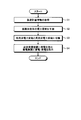
- FIG. 3 is a flowchart illustrating an example of a processing procedure of the power control apparatus in the power system according to the embodiment of the present invention.
- FIG. 4 is a diagram illustrating an example of the power system according to the embodiment of the present invention, and is a graph illustrating fluctuations in the total demand power amount, the power generation amount, the power sale amount, and the power storage amount in the steelworks.
- the power system 1 is a system used in a steel plant, and includes a power control device 10, a database (DB) 20, a power transmission line 30, a private power generation device 40, a power storage device 50, a hot rolling factory 60, and others.
- DB database
- a factory 70, a transmission line 80, an external power supply and demand device 90, and a connection point 100 are provided.
- the database 20 is provided in the steelworks, and accumulates power consumption information, generated power information, stored power information, and manufacturing plan information.
- the power consumption information is information regarding power consumption from the past to the present at the hot rolling factory 60 and the other factory 70.
- the generated power information is information related to the generated power from the past to the present in the private power generator 40.
- the stored power information is information regarding stored power from the past to the present in the power storage device 50.
- the production plan information is information relating to product production plans in the hot rolling factory 60 and other factories 70, and more specifically, information relating to which materials are processed and when products or intermediate products are produced. is there.
- the power transmission line 30 is connected to a private power generation device 40, a power storage device 50, a hot rolling factory 60, another factory 70, and an external power supply / demand apparatus 90, and transmits power between them. That is, the private power generation device 40, the power storage device 50, the hot rolling factory 60, the other factory 70, and the external power supply / demand device 90 supply power through the power transmission line 30 and receive power through the power transmission line 30.
- the private power generation device 40 is provided in the steelworks, and specifically, is a thermal power plant using in-house generated gas or LNG.
- the private power generation device 40 supplies the generated power to the hot rolling factory 60 and the other factory 70 via the transmission line 30.
- the private power generation apparatus 40 sells the surplus power to the external power supply / demand apparatus 90 via the transmission line 30.
- the power storage device 50 is provided in the ironworks and stores the electric power generated by the private power generation device 40. Then, the power storage device 50 supplies the stored power to the hot rolling factory 60 and the other factory 70 via the power transmission line 30. In addition, when surplus power is generated, the power storage device 50 sells the surplus power to the external power supply and demand device 90 via the transmission line 30.
- the power storage device 50 uses a device that has a faster response speed to fluctuations in power demand than the private power generation device 40. Moreover, as the electrical storage apparatus 50, a flywheel apparatus, a secondary battery, a capacitor, etc. can be used, for example.
- the hot rolling factory 60 and the other factory 70 are provided in the steel works and have power demand facilities (for example, rolling mills).
- the other factory 70 is specifically a manufacturing factory such as a steelmaking factory or a plank factory.
- the transmission path 80 is connected to the private power generation device 40, the power storage device 50, the hot rolling factory 60, and the other factory 70, and transmits information therebetween. That is, the private power generation device 40, the power storage device 50, the hot rolling factory 60, and the other factory 70 exchange information on power consumption information, generated power information, stored power information, and manufacturing plan information via the transmission path 80.
- the external power supply and demand device 90 is provided outside the steelworks, for example, a power plant of an electric power company. As shown in FIG. 1, the external power supply and demand apparatus 90 is connected to the power transmission line 30 in the steel works via the connection point 100, and supplies power to the hot rolling factory 60 and other factories 70 as necessary. Supply. In addition, the power system 1 sells surplus power generated by the private power generation device 40 to the external power supply and demand device 90 via the transmission line 30.
- the power control apparatus 10 is realized by a general-purpose information processing apparatus such as a personal computer or a workstation.
- the processing unit 11, the ROM 12, the RAM 13, and the transmission A path 14 and an input / output port 15 are provided.
- the arithmetic processing unit 11, the ROM 12, and the RAM 13 are configured to be able to transmit and receive data to and from each other via the transmission path 14.
- the arithmetic processing unit 11, the ROM 12, and the RAM 13 are configured to transmit and receive data to and from the database 20 and the transmission path 80 via the input / output port 15.
- the arithmetic processing unit 11 is realized by hardware such as a CPU.
- the arithmetic processing unit 11 supervises the overall operation of the power control device 10 by instructing each unit of the power control device 10 and transferring data based on various programs and data information stored in the ROM 12. Control.
- the arithmetic processing unit 11 functions as a manufacturing plan acquisition unit 111, a power demand prediction unit 112, a power fluctuation separation unit 113, and a power generation / storage instruction unit 114.
- the ROM 12 stores a program for operating the power control apparatus 10 and realizing various functions provided in the power control apparatus 10, data used during the execution of these programs, and the like.
- a power control program 121 for causing the arithmetic processing unit 11 to function as the manufacturing plan acquisition unit 111, the power demand prediction unit 112, the power fluctuation separation unit 113, and the power generation / storage instruction unit 114, and to execute a power control process described later is stored. Is done.
- the RAM 13 is a semiconductor memory used as a working memory for the arithmetic processing unit 11, and includes a memory area that temporarily stores a program executed by the arithmetic processing unit 11, data used during the execution, and the like.
- the power control process is realized in the power control apparatus 10 by the arithmetic processing unit 11 reading and executing the power control program 121 stored in the ROM 12 and performing the process according to the procedure shown in FIG.
- the process shown in the figure is repeatedly executed every predetermined control cycle.
- the control cycle here indicates a timing (for example, a 30-minute pitch) for evaluating how much the power sale integrated value can follow the target value.
- Step S1 In the process of step S ⁇ b> 1, the manufacturing plan acquisition unit 111 of the power control apparatus 10 acquires manufacturing plan information of the hot rolling factory 60 and the other factory 70 from the database 20.
- the time of N ⁇ ⁇ t is the above-described control cycle, and is a period for evaluating the power purchase amount integrated value.
- ⁇ t is determined in consideration of a rolling pitch or the like (for example, a time of about 5 minutes including a plurality of rolling opportunities).
- the power control apparatus 10 adds the fluctuation of the demand power amount of the hot rolling factory 60 from the time t calculated by the above formula (1) to t + N ⁇ ⁇ t and the fluctuation of the demand power amount of the other factory 70, Predict fluctuations in the total power demand in the steelworks (the power demand of the entire steelworks). It should be noted that fluctuations in the amount of power demand for other factories 70 are trend predictions (for example, if the moving average method is used, the actual power amount average value in the immediately preceding evaluation period or the like is used as the predicted value, and if the linear regression method is used, the immediately preceding predetermined period is used. Prediction based on the linear regression formula of
- step S3 the power fluctuation separation unit 113 of the power control apparatus 10 adds the amount of power sold from time t to t + N ⁇ ⁇ t to the change in total demand power in the ironworks from time t to t + N ⁇ ⁇ t.
- the power generation amount is calculated, and the calculated target power generation amount is separated into low frequency power fluctuation and high frequency power fluctuation.
- the amount of power sold at each time from t to t + N ⁇ ⁇ t (between t + i ⁇ ⁇ t to t + (i + 1) ⁇ ⁇ t) is a constant obtained by multiplying the target value of the accumulated power sale value by (1 / N ⁇ ⁇ t). Value.
- the low-frequency power fluctuation indicates a fluctuation in power demand that can be followed by an increase or decrease in the amount of power generated by the private power generator 40.
- the private power generator 40 generally has low responsiveness to fluctuations in power demand, and cannot supply power immediately in response to a sudden demand for power.
- the low-frequency power fluctuation described above is a slow fluctuation in power demand that can supply power even with such a private power generator 40.
- the high-frequency power fluctuation indicates a fluctuation in power demand that cannot be followed by an increase or decrease in the amount of power generated by the private power generator 40. That is, the high-frequency power fluctuation is a rapid fluctuation in power demand that cannot be supplied by the private power generation apparatus 40 with low response as described above.
- the high-frequency power fluctuation is also a fluctuation in power demand that can be tracked by power storage or discharge by the power storage device 50.
- the power storage device 50 generally has high responsiveness to fluctuations in power demand (for example, on the order of msec), and can supply power immediately in response to a sudden demand for power. Therefore, even if there is a high-frequency power fluctuation that cannot be supplied by the private power generation device 40, the power storage device 50 can supply power.
- the power fluctuation separation unit 113 uses, for example, the maximum power fluctuation frequency that can be followed by the private power generation apparatus 40 as a reference, sets power fluctuations below the frequency as low-frequency power fluctuations, and power fluctuations exceeding the frequency as high-frequency power fluctuations. Thus, the high frequency power fluctuation and the low frequency power fluctuation are separated.
- Step S4 In step S ⁇ b> 4, the power generation / storage instruction unit 114 of the power control device 10 transmits an instruction amount as time-series data of the power generation amount corresponding to the low frequency power fluctuation to the private power generation device 40. As a result, the private power generation device 40 changes the power generation amount according to the received power generation amount.
- the power generation / storage instruction unit 114 transmits an instruction amount of the storage amount / discharge amount according to the high-frequency power fluctuation to the storage device 50.
- the power storage device 50 changes the power storage amount / discharge amount in the control cycle of the msec order by the control device provided inside the power storage device 50 according to the received instruction amount as the time series data of the power storage amount / discharge amount. It should be noted that higher cycle power fluctuations that cannot be absorbed even by the charge / discharge instruction of power storage device 50 (for example, less than m seconds) are absorbed by power flow control in external power supply and demand device 90.
- the power generation amount is instructed to the private power generation device 40 based on the fluctuation in power demand predicted based on the manufacturing plan information, and the power storage device 50 is instructed. Instruct to store and discharge. That is, among the fluctuations in the future power demand predicted from the production plan, for the slow fluctuations (low frequency power fluctuations) that can be followed by the power generation by the private power generator 40, the power generated by the private power generator 40 is supplied. To do. On the other hand, for rapid fluctuations (high-frequency power fluctuations) that cannot be followed by power generation by the private power generation device 40, the power storage device 50 having higher responsiveness than the private power generation device 40 is used, and power is supplied or discharged. If there is a surplus, charge is performed. Therefore, according to the power system 1, when surplus power is sold to the external power network, the amount of power sold to the external power network can be controlled in consideration of the power supply and demand of the entire power system 1.
- the present invention is applied to the total demand power amount in the steelworks, the power generation amount by the private power generation device 40, the power sale amount, and the power storage amount variation by the power storage device 50 in two hours from 14:00 to 16:00. It is the graph compared with the case and the conventional case which does not apply this invention.
- low frequency power fluctuations are indicated by broken lines
- high frequency power fluctuations are indicated by solid lines.
- the power generation amount is increased in the upward direction of the graph, and is represented by an integrated value for 30 minutes (see “Factory integrated 30-minute integration” in the figure), and is reset every 30 minutes.
- the amount of electric power sold is increasing in the lower direction of the graph, and is represented by an integrated value for 30 minutes (see “Integrated 30 minutes of power retail” in the figure), and is reset every 30 minutes.
- the amount of electricity stored is increasing in the upward direction of the graph, and is stored when it goes upward, and discharged when it goes downward.
- the power sale target value is, for example, a value determined by an agreement with an electric power company that owns the external power supply and demand apparatus 90, and is an integrated value of the amount of power sold every 30 minutes. That is, the cycle of the control process shown in FIG. 3 is 30 minutes in this embodiment.
- the amount of power sold at 15:00 and 16:00 exceeds the power sales target value. This indicates that the private power generation apparatus 40 cannot follow the high frequency power fluctuation and has generated extra power. Further, in the conventional method, the amount of power sold at 15:30 is less than the power sales target value. This indicates that the private power generator 40 cannot follow the high-frequency power fluctuation and cannot generate power. Thus, with the conventional method, it is difficult to match the power sale amount with the power sale target value.
- the surplus power is stored by the power storage device 50, so that the power sales amount falls within the power sales target value at 15:00, 15:30, and 16:00. Yes. That is, at 14:30 to 15:00 and 15:30 to 16:00, excess power generated by the private power generation device 40 is stored by the power storage device 50, and from 15:00 to 15:30, the private power generation device.
- the electric power that is insufficient only by the power generation by 40 is supplied by the discharge by the power storage device 50.
- the power generation / storage instruction unit 114 of the power control device 10 transmits an instruction amount of the storage amount / discharge amount according to the high-frequency power fluctuation to the storage device 50, This can be realized by changing the amount of stored electricity / the amount of discharge of the power storage device 50.
- step S4 of FIG. 3 the power generation / storage instruction unit 114 of the power control apparatus 10 transmits an instruction amount of the power generation amount corresponding to the low frequency power fluctuation to the private power generation apparatus 40, and private power generation This can be realized by changing the power generation amount of the device 40.
- the present invention can be applied to an electric power system because the amount of electric power sold can be controlled in consideration of the electric power demand of the entire system.
Landscapes
- Engineering & Computer Science (AREA)
- Power Engineering (AREA)
- Business, Economics & Management (AREA)
- Health & Medical Sciences (AREA)
- Economics (AREA)
- Public Health (AREA)
- Water Supply & Treatment (AREA)
- General Health & Medical Sciences (AREA)
- Human Resources & Organizations (AREA)
- Marketing (AREA)
- Primary Health Care (AREA)
- Strategic Management (AREA)
- Tourism & Hospitality (AREA)
- Physics & Mathematics (AREA)
- General Business, Economics & Management (AREA)
- General Physics & Mathematics (AREA)
- Theoretical Computer Science (AREA)
- Supply And Distribution Of Alternating Current (AREA)
Abstract
Description
まず、本発明が適用される電力システム1の構成について、図1を参照しながら説明する。電力システム1は、製鉄所内で用いられるシステムであり、電力制御装置10と、データベース(DB)20と、送電線30と、自家発電装置40と、蓄電装置50と、熱延工場60と、その他工場70と、伝送路80と、外部電力需給装置90と、連結点100と、を備えている。
次に、電力システム1における電力制御装置10の構成について、図2を参照しながら説明する。電力制御装置10は、具体的にはパーソナルコンピュータやワークステーション等の汎用の情報処理装置によって実現されるものであり、同図に示すように、演算処理部11と、ROM12と、RAM13と、伝送路14と、入出力ポート15と、を備えている。演算処理部11、ROM12およびRAM13は、伝送路14を介して、互いにデータを送受信可能に構成されている。また、演算処理部11、ROM12およびRAM13は、入出力ポート15を介して、データベース20および伝送路80にデータを送受信可能に構成されている。
次に、電力制御装置10による電力制御処理について、図3を参照しながら説明する。電力制御処理は、具体的には、電力制御装置10において、演算処理部11がROM12に格納された電力制御プログラム121を読み出して実行し、図3に示した手順に従って処理を行うことで実現される。なお、同図に示した処理は、所定の制御周期ごとに繰り返し実行される。ここでいう制御周期とは、売電量積算値が目標値にどれだけ追従できているかを評価するタイミング(例えば、30分ピッチ)のことを示している。
ステップS1の処理では、電力制御装置10の製造計画取得部111が、データベース20から、熱延工場60およびその他工場70の製造計画情報を取得する。
ステップS2の処理では、電力制御装置10の電力需要予測部112が、ステップS1で取得した製造計画情報に基づいて、将来にわたる各工場の電力需要(需要電力量)をΔtで離散化した時系列データとして予測する。例えば熱延工場60の場合、製造計画情報と下記式(1)を用いて、時刻t+i・Δt~t+(i+1)・Δtの間の需要電力量を算出する。この予測をi=0,1,2,・・・,N-1まで求めることにより、時刻tからt+N・Δtまでの電力需要の変動を予測する。ここで、N・Δtの時間が上述の制御周期であり、買電量積算値を評価する期間である。また、Δtは、圧延ピッチ等を考慮して定める(例えば複数の圧延チャンスを含む5分程度の時間等)。
P:時刻t+i・Δt~t+(i+1)・Δtにおける熱延需要電力量
s:時刻t+i・Δt~t+(i+1)・Δtにおける圧延スラブ番号
W(s):スラブsの重量
R(s):スラブsの圧延機における圧下量
α:係数
Δt:
ステップS3では、電力制御装置10の電力変動分離部113が、時刻tからt+N・Δtまでの製鉄所内の総需要電力量の変動に時刻tからt+N・Δtまでの売電量を足し合わせることにより目標発電量を算出し、算出された目標発電量を、低周波電力変動と高周波電力変動とに分離する。なお、時刻tからt+N・Δtまでの各時刻(t+i・Δt~t+(i+1)・Δtの間)の売電量は、売電量積算値の目標値に(1/N・Δt)を乗じた一定値とする。
ステップS4では、電力制御装置10の発電蓄電指示部114が、低周波電力変動に応じた発電量の時系列データとしての指示量を自家発電装置40に送信する。その結果、自家発電装置40は、受信した発電量の指示量に従って発電量を変更する。
10 電力制御装置
11 演算処理部
111 製造計画取得部
112 電力需要予測部
113 電力変動分離部
114 発電蓄電指示部
12 ROM
121 電力制御プログラム
13 RAM
14 伝送路
15 入出力ポート
20 データベース
30 送電線
40 自家発電装置
50 蓄電装置
60 熱延工場
70 その他工場
80 伝送路
90 外部電力需給装置
100 連結点
Claims (5)
- 電力需要設備を有する工場と、発電した電力を前記工場に対して供給する自家発電装置と、前記工場と前記自家発電装置とを結ぶ送電線と、を備え、前記送電線を介して、余剰電力を外部電力需給装置に対して売電する電力システムにおいて、
前記送電線に接続され、前記自家発電装置によって発電された電力を蓄電するとともに、蓄電した電力を前記工場に対して供給する蓄電装置と、
前記工場の製造計画情報が蓄積されたデータベースと、
前記製造計画情報に基づいて前記工場における将来の電力需要を予測し、予測された電力需要の変動に基づいて、前記自家発電装置に対して発電量の変更を指示するとともに、前記蓄電装置に対して蓄電および放電を指示する電力制御装置と、
を備えることを特徴とする電力システム。 - 前記電力制御装置は、
前記データベースから前記製造計画情報を取得する製造計画取得部と、
前記製造計画情報に基づいて前記工場における将来の電力需要を予測する電力需要予測部と、
前記電力需要の変動から、前記自家発電装置によって追従可能な電力変動である低周波電力変動と、前記自家発電装置によって追従不可能かつ前記蓄電装置によって追従可能な電力変動である高周波電力変動と、を分離する電力変動分離部と、
前記低周波電力変動に応じた発電量を前記自家発電装置に対して指示するとともに、前記高周波電力変動に応じた蓄電量または放電量を前記蓄電装置に対して指示する発電蓄電指示部と、
を備えることを特徴とする請求項1に記載の電力システム。 - 前記蓄電装置は、前記自家発電装置と比較して、電力需要の変動に対する応答速度が速いことを特徴とする請求項1または請求項2に記載の電力システム。
- 前記蓄電装置は、フライホイール装置、二次電池またはキャパシタであることを特徴とする請求項3に記載の電力システム。
- 製鉄所内のシステムであることを特徴とする請求項1から請求項4のいずれか一項に記載の電力システム。
Priority Applications (3)
| Application Number | Priority Date | Filing Date | Title |
|---|---|---|---|
| CN201680042292.2A CN107851999B (zh) | 2015-07-22 | 2016-07-22 | 电力系统 |
| KR1020187001180A KR102006581B1 (ko) | 2015-07-22 | 2016-07-22 | 전력 시스템 |
| JP2016564649A JP6365686B2 (ja) | 2015-07-22 | 2016-07-22 | 電力システム |
Applications Claiming Priority (2)
| Application Number | Priority Date | Filing Date | Title |
|---|---|---|---|
| JP2015144655 | 2015-07-22 | ||
| JP2015-144655 | 2015-07-22 |
Publications (1)
| Publication Number | Publication Date |
|---|---|
| WO2017014293A1 true WO2017014293A1 (ja) | 2017-01-26 |
Family
ID=57835095
Family Applications (1)
| Application Number | Title | Priority Date | Filing Date |
|---|---|---|---|
| PCT/JP2016/071511 Ceased WO2017014293A1 (ja) | 2015-07-22 | 2016-07-22 | 電力システム |
Country Status (4)
| Country | Link |
|---|---|
| JP (1) | JP6365686B2 (ja) |
| KR (1) | KR102006581B1 (ja) |
| CN (1) | CN107851999B (ja) |
| WO (1) | WO2017014293A1 (ja) |
Cited By (1)
| Publication number | Priority date | Publication date | Assignee | Title |
|---|---|---|---|---|
| JP7042984B1 (ja) * | 2021-02-26 | 2022-03-28 | 三菱電機株式会社 | 指令装置、充放電制御システム、電力制御システム、中央指令装置、整定値管理装置、充放電制御方法およびプログラム |
Families Citing this family (1)
| Publication number | Priority date | Publication date | Assignee | Title |
|---|---|---|---|---|
| JP2021022112A (ja) * | 2019-07-26 | 2021-02-18 | トヨタ自動車株式会社 | エネルギー管理システム |
Citations (3)
| Publication number | Priority date | Publication date | Assignee | Title |
|---|---|---|---|---|
| JP2013093917A (ja) * | 2011-10-24 | 2013-05-16 | Panasonic Corp | エネルギーマネジメント装置、エネルギーマネジメントシステムおよびプログラム |
| WO2013121514A1 (ja) * | 2012-02-14 | 2013-08-22 | 東芝三菱電機産業システム株式会社 | 電力平準化装置 |
| JP2014217198A (ja) * | 2013-04-26 | 2014-11-17 | 株式会社東芝 | 蓄電量管理装置及び蓄電量管理システム |
Family Cites Families (9)
| Publication number | Priority date | Publication date | Assignee | Title |
|---|---|---|---|---|
| EP2075891B1 (en) * | 2006-10-16 | 2014-01-01 | Vpec, Inc. | Electric power system |
| JP2012249476A (ja) * | 2011-05-30 | 2012-12-13 | Panasonic Corp | 電力供給システム |
| KR101243192B1 (ko) * | 2011-08-02 | 2013-03-25 | 한국전기연구원 | 풍력발전 설비 출력 제어 방법 및 시스템 |
| KR101846026B1 (ko) * | 2011-10-25 | 2018-04-06 | 한국전력공사 | 사전 전력수요예측에 의한 전력수요관리 방법 및 시스템 |
| JP5957235B2 (ja) * | 2012-01-30 | 2016-07-27 | 株式会社東芝 | 運転計画システム |
| JP2014050256A (ja) * | 2012-08-31 | 2014-03-17 | Hitachi Ltd | 工場エネルギー管理システム、電力管理装置および工場エネルギー管理方法 |
| JP6054122B2 (ja) * | 2012-09-28 | 2016-12-27 | 株式会社東芝 | 鉄道電力管理装置 |
| JP6043576B2 (ja) | 2012-10-10 | 2016-12-14 | 株式会社日立製作所 | 蓄電池システム及び発電プラント制御システム |
| KR101397746B1 (ko) * | 2012-11-20 | 2014-05-21 | 한국과학기술원 | 스마트 전력 관리 방법 및 시스템 |
-
2016
- 2016-07-22 KR KR1020187001180A patent/KR102006581B1/ko active Active
- 2016-07-22 CN CN201680042292.2A patent/CN107851999B/zh active Active
- 2016-07-22 JP JP2016564649A patent/JP6365686B2/ja active Active
- 2016-07-22 WO PCT/JP2016/071511 patent/WO2017014293A1/ja not_active Ceased
Patent Citations (3)
| Publication number | Priority date | Publication date | Assignee | Title |
|---|---|---|---|---|
| JP2013093917A (ja) * | 2011-10-24 | 2013-05-16 | Panasonic Corp | エネルギーマネジメント装置、エネルギーマネジメントシステムおよびプログラム |
| WO2013121514A1 (ja) * | 2012-02-14 | 2013-08-22 | 東芝三菱電機産業システム株式会社 | 電力平準化装置 |
| JP2014217198A (ja) * | 2013-04-26 | 2014-11-17 | 株式会社東芝 | 蓄電量管理装置及び蓄電量管理システム |
Cited By (2)
| Publication number | Priority date | Publication date | Assignee | Title |
|---|---|---|---|---|
| JP7042984B1 (ja) * | 2021-02-26 | 2022-03-28 | 三菱電機株式会社 | 指令装置、充放電制御システム、電力制御システム、中央指令装置、整定値管理装置、充放電制御方法およびプログラム |
| WO2022180799A1 (ja) * | 2021-02-26 | 2022-09-01 | 三菱電機株式会社 | 指令装置、充放電制御システム、電力制御システム、中央指令装置、整定値管理装置、蓄電池、充放電制御方法およびプログラム |
Also Published As
| Publication number | Publication date |
|---|---|
| CN107851999B (zh) | 2020-10-16 |
| JP6365686B2 (ja) | 2018-08-01 |
| KR102006581B1 (ko) | 2019-08-01 |
| CN107851999A (zh) | 2018-03-27 |
| JPWO2017014293A1 (ja) | 2017-07-27 |
| KR20180017171A (ko) | 2018-02-20 |
Similar Documents
| Publication | Publication Date | Title |
|---|---|---|
| Zhang et al. | Bidding strategy in energy and spinning reserve markets for aluminum smelters' demand response | |
| TWI397864B (zh) | 能量儲存裝置之運轉計畫製作方法以及運轉計畫製作裝置 | |
| JP4808754B2 (ja) | 自然エネルギー発電制御システム | |
| JP4189930B2 (ja) | マイクログリッドの電力監視計測制御システム、その電力監視計測制御方法及びその電力監視計測制御プログラム | |
| JP5402569B2 (ja) | 経済負荷配分制御装置及び経済負荷配分制御方法 | |
| WO2019080930A1 (zh) | 电网等风险状态检修决策方法 | |
| JP7120600B2 (ja) | 処理装置、処理方法及びプログラム | |
| TWI524619B (zh) | 電力管理裝置 | |
| Sarkar et al. | Optimal reliability, production lotsize and safety stock: An economic manufacturing quantity model | |
| JP6365686B2 (ja) | 電力システム | |
| Zhao et al. | Predictive maintenance policy based on process data | |
| Fang et al. | An adaptive job shop scheduling mechanism for disturbances by running reinforcement learning in digital twin environment | |
| JPWO2014042219A1 (ja) | 電力管理方法、電力管理装置およびプログラム | |
| JP2010015207A (ja) | エネルギ管理システム | |
| JP6157901B2 (ja) | 電力系統の需給制御システム及び需給制御装置 | |
| JP6641867B2 (ja) | 消費電力量予測方法、装置及びプログラム | |
| CN118899878A (zh) | 一种运用储能和可控负荷进行需量平抑的方法和装置 | |
| JP2017070134A (ja) | 電力予測方法 | |
| Yao et al. | Design, implementation and testing of an intelligent knowledge-based system for the supervisory control of a hot rolling mill | |
| JP7355712B2 (ja) | 炉稼働管理装置、炉稼働管理方法、および炉稼働管理プログラム | |
| CN118709571B (zh) | 考虑老化趋势的电缆剩余寿命预测方法及系统 | |
| JP2017022939A (ja) | エネルギー需給計画装置及びプログラム | |
| JP2023142394A5 (ja) | ||
| JP2006254649A (ja) | 発電機評価方法および発電機評価装置 | |
| JP2020061796A (ja) | 運転計画最適化装置 |
Legal Events
| Date | Code | Title | Description |
|---|---|---|---|
| ENP | Entry into the national phase |
Ref document number: 2016564649 Country of ref document: JP Kind code of ref document: A |
|
| 121 | Ep: the epo has been informed by wipo that ep was designated in this application |
Ref document number: 16827853 Country of ref document: EP Kind code of ref document: A1 |
|
| ENP | Entry into the national phase |
Ref document number: 20187001180 Country of ref document: KR Kind code of ref document: A |
|
| NENP | Non-entry into the national phase |
Ref country code: DE |
|
| 122 | Ep: pct application non-entry in european phase |
Ref document number: 16827853 Country of ref document: EP Kind code of ref document: A1 |