WO2017014172A1 - Metal mask substrate for vapor deposition, metal mask for vapor deposition, production method for metal mask substrate for vapor deposition, and production method for metal mask for vapor deposition - Google Patents
Metal mask substrate for vapor deposition, metal mask for vapor deposition, production method for metal mask substrate for vapor deposition, and production method for metal mask for vapor deposition Download PDFInfo
- Publication number
- WO2017014172A1 WO2017014172A1 PCT/JP2016/070951 JP2016070951W WO2017014172A1 WO 2017014172 A1 WO2017014172 A1 WO 2017014172A1 JP 2016070951 W JP2016070951 W JP 2016070951W WO 2017014172 A1 WO2017014172 A1 WO 2017014172A1
- Authority
- WO
- WIPO (PCT)
- Prior art keywords
- vapor deposition
- mask
- nickel
- metal mask
- metal sheet
- Prior art date
Links
Images


Classifications
-
- C—CHEMISTRY; METALLURGY
- C23—COATING METALLIC MATERIAL; COATING MATERIAL WITH METALLIC MATERIAL; CHEMICAL SURFACE TREATMENT; DIFFUSION TREATMENT OF METALLIC MATERIAL; COATING BY VACUUM EVAPORATION, BY SPUTTERING, BY ION IMPLANTATION OR BY CHEMICAL VAPOUR DEPOSITION, IN GENERAL; INHIBITING CORROSION OF METALLIC MATERIAL OR INCRUSTATION IN GENERAL
- C23C—COATING METALLIC MATERIAL; COATING MATERIAL WITH METALLIC MATERIAL; SURFACE TREATMENT OF METALLIC MATERIAL BY DIFFUSION INTO THE SURFACE, BY CHEMICAL CONVERSION OR SUBSTITUTION; COATING BY VACUUM EVAPORATION, BY SPUTTERING, BY ION IMPLANTATION OR BY CHEMICAL VAPOUR DEPOSITION, IN GENERAL
- C23C14/00—Coating by vacuum evaporation, by sputtering or by ion implantation of the coating forming material
- C23C14/04—Coating on selected surface areas, e.g. using masks
- C23C14/042—Coating on selected surface areas, e.g. using masks using masks
-
- C—CHEMISTRY; METALLURGY
- C23—COATING METALLIC MATERIAL; COATING MATERIAL WITH METALLIC MATERIAL; CHEMICAL SURFACE TREATMENT; DIFFUSION TREATMENT OF METALLIC MATERIAL; COATING BY VACUUM EVAPORATION, BY SPUTTERING, BY ION IMPLANTATION OR BY CHEMICAL VAPOUR DEPOSITION, IN GENERAL; INHIBITING CORROSION OF METALLIC MATERIAL OR INCRUSTATION IN GENERAL
- C23C—COATING METALLIC MATERIAL; COATING MATERIAL WITH METALLIC MATERIAL; SURFACE TREATMENT OF METALLIC MATERIAL BY DIFFUSION INTO THE SURFACE, BY CHEMICAL CONVERSION OR SUBSTITUTION; COATING BY VACUUM EVAPORATION, BY SPUTTERING, BY ION IMPLANTATION OR BY CHEMICAL VAPOUR DEPOSITION, IN GENERAL
- C23C14/00—Coating by vacuum evaporation, by sputtering or by ion implantation of the coating forming material
- C23C14/22—Coating by vacuum evaporation, by sputtering or by ion implantation of the coating forming material characterised by the process of coating
- C23C14/24—Vacuum evaporation
-
- C—CHEMISTRY; METALLURGY
- C23—COATING METALLIC MATERIAL; COATING MATERIAL WITH METALLIC MATERIAL; CHEMICAL SURFACE TREATMENT; DIFFUSION TREATMENT OF METALLIC MATERIAL; COATING BY VACUUM EVAPORATION, BY SPUTTERING, BY ION IMPLANTATION OR BY CHEMICAL VAPOUR DEPOSITION, IN GENERAL; INHIBITING CORROSION OF METALLIC MATERIAL OR INCRUSTATION IN GENERAL
- C23F—NON-MECHANICAL REMOVAL OF METALLIC MATERIAL FROM SURFACE; INHIBITING CORROSION OF METALLIC MATERIAL OR INCRUSTATION IN GENERAL; MULTI-STEP PROCESSES FOR SURFACE TREATMENT OF METALLIC MATERIAL INVOLVING AT LEAST ONE PROCESS PROVIDED FOR IN CLASS C23 AND AT LEAST ONE PROCESS COVERED BY SUBCLASS C21D OR C22F OR CLASS C25
- C23F1/00—Etching metallic material by chemical means
- C23F1/02—Local etching
-
- C—CHEMISTRY; METALLURGY
- C25—ELECTROLYTIC OR ELECTROPHORETIC PROCESSES; APPARATUS THEREFOR
- C25B—ELECTROLYTIC OR ELECTROPHORETIC PROCESSES FOR THE PRODUCTION OF COMPOUNDS OR NON-METALS; APPARATUS THEREFOR
- C25B11/00—Electrodes; Manufacture thereof not otherwise provided for
- C25B11/04—Electrodes; Manufacture thereof not otherwise provided for characterised by the material
- C25B11/051—Electrodes formed of electrocatalysts on a substrate or carrier
- C25B11/055—Electrodes formed of electrocatalysts on a substrate or carrier characterised by the substrate or carrier material
-
- C—CHEMISTRY; METALLURGY
- C25—ELECTROLYTIC OR ELECTROPHORETIC PROCESSES; APPARATUS THEREFOR
- C25C—PROCESSES FOR THE ELECTROLYTIC PRODUCTION, RECOVERY OR REFINING OF METALS; APPARATUS THEREFOR
- C25C1/00—Electrolytic production, recovery or refining of metals by electrolysis of solutions
- C25C1/06—Electrolytic production, recovery or refining of metals by electrolysis of solutions or iron group metals, refractory metals or manganese
- C25C1/08—Electrolytic production, recovery or refining of metals by electrolysis of solutions or iron group metals, refractory metals or manganese of nickel or cobalt
-
- C—CHEMISTRY; METALLURGY
- C25—ELECTROLYTIC OR ELECTROPHORETIC PROCESSES; APPARATUS THEREFOR
- C25C—PROCESSES FOR THE ELECTROLYTIC PRODUCTION, RECOVERY OR REFINING OF METALS; APPARATUS THEREFOR
- C25C7/00—Constructional parts, or assemblies thereof, of cells; Servicing or operating of cells
- C25C7/06—Operating or servicing
- C25C7/08—Separating of deposited metals from the cathode
-
- C—CHEMISTRY; METALLURGY
- C25—ELECTROLYTIC OR ELECTROPHORETIC PROCESSES; APPARATUS THEREFOR
- C25D—PROCESSES FOR THE ELECTROLYTIC OR ELECTROPHORETIC PRODUCTION OF COATINGS; ELECTROFORMING; APPARATUS THEREFOR
- C25D1/00—Electroforming
-
- C—CHEMISTRY; METALLURGY
- C25—ELECTROLYTIC OR ELECTROPHORETIC PROCESSES; APPARATUS THEREFOR
- C25D—PROCESSES FOR THE ELECTROLYTIC OR ELECTROPHORETIC PRODUCTION OF COATINGS; ELECTROFORMING; APPARATUS THEREFOR
- C25D1/00—Electroforming
- C25D1/04—Wires; Strips; Foils
-
- C—CHEMISTRY; METALLURGY
- C25—ELECTROLYTIC OR ELECTROPHORETIC PROCESSES; APPARATUS THEREFOR
- C25D—PROCESSES FOR THE ELECTROLYTIC OR ELECTROPHORETIC PRODUCTION OF COATINGS; ELECTROFORMING; APPARATUS THEREFOR
- C25D1/00—Electroforming
- C25D1/10—Moulds; Masks; Masterforms
-
- C—CHEMISTRY; METALLURGY
- C25—ELECTROLYTIC OR ELECTROPHORETIC PROCESSES; APPARATUS THEREFOR
- C25D—PROCESSES FOR THE ELECTROLYTIC OR ELECTROPHORETIC PRODUCTION OF COATINGS; ELECTROFORMING; APPARATUS THEREFOR
- C25D11/00—Electrolytic coating by surface reaction, i.e. forming conversion layers
- C25D11/02—Anodisation
- C25D11/34—Anodisation of metals or alloys not provided for in groups C25D11/04 - C25D11/32
-
- H—ELECTRICITY
- H10—SEMICONDUCTOR DEVICES; ELECTRIC SOLID-STATE DEVICES NOT OTHERWISE PROVIDED FOR
- H10K—ORGANIC ELECTRIC SOLID-STATE DEVICES
- H10K71/00—Manufacture or treatment specially adapted for the organic devices covered by this subclass
-
- H—ELECTRICITY
- H10—SEMICONDUCTOR DEVICES; ELECTRIC SOLID-STATE DEVICES NOT OTHERWISE PROVIDED FOR
- H10K—ORGANIC ELECTRIC SOLID-STATE DEVICES
- H10K71/00—Manufacture or treatment specially adapted for the organic devices covered by this subclass
- H10K71/10—Deposition of organic active material
- H10K71/16—Deposition of organic active material using physical vapour deposition [PVD], e.g. vacuum deposition or sputtering
- H10K71/166—Deposition of organic active material using physical vapour deposition [PVD], e.g. vacuum deposition or sputtering using selective deposition, e.g. using a mask
-
- C—CHEMISTRY; METALLURGY
- C25—ELECTROLYTIC OR ELECTROPHORETIC PROCESSES; APPARATUS THEREFOR
- C25D—PROCESSES FOR THE ELECTROLYTIC OR ELECTROPHORETIC PRODUCTION OF COATINGS; ELECTROFORMING; APPARATUS THEREFOR
- C25D3/00—Electroplating: Baths therefor
- C25D3/02—Electroplating: Baths therefor from solutions
- C25D3/56—Electroplating: Baths therefor from solutions of alloys
- C25D3/562—Electroplating: Baths therefor from solutions of alloys containing more than 50% by weight of iron or nickel or cobalt
Definitions
- the present invention relates to a metal mask substrate for vapor deposition, a metal mask for vapor deposition, a method for producing a metal mask substrate for vapor deposition, and a method for producing a metal mask for vapor deposition.
- An organic EL display is known as one of display devices manufactured using a vapor deposition method.
- the organic layer provided in the organic EL display is a deposit of organic molecules sublimated in the vapor deposition process.
- the mask hole provided in the metal mask for vapor deposition used in the vapor deposition step is a passage through which the sublimated organic molecules are directed toward the substrate.
- the opening which a mask hole has has a shape according to the shape of the pixel with which an organic EL display is equipped (for example, refer patent document 1).
- the method of manufacturing the metal mask for vapor deposition includes the process of forming opening in the metal mask base material for vapor deposition.
- the step of forming the opening for example, formation of a resist mask using a photolithography method and wet etching using the resist mask are performed.
- an exposure target region in the resist layer located on the surface of the metal mask base material for vapor deposition is exposed.
- at least a part of the light irradiated to the resist layer is scattered on the surface of the metal mask base material for vapor deposition, and a part of the scattered light is irradiated to a part other than the exposure target area in the resist layer.
- the present invention relates to a metal mask base material for vapor deposition, a metal mask for vapor deposition, a method for producing a metal mask base material for vapor deposition, and a metal for vapor deposition that can improve the structural accuracy of the opening of the metal mask for vapor deposition
- An object is to provide a method for manufacturing a mask.
- a metal mask base material for vapor deposition for solving the above-described problem includes a nickel-containing metal sheet having a front surface and a back surface that is a surface opposite to the front surface, and at least one of the front surface and the back surface is a resist.
- the target surface on which the layer is located, the surface roughness Sa of the target surface is 0.019 ⁇ m or less, and the surface roughness Sz of the target surface is 0.308 ⁇ m or less.
- the reflectance by regular reflection of light incident on the target surface may be 53.0% or more and 97.0% or less.
- the nickel-containing metal sheet may be an invar sheet.
- a metal mask base material for vapor deposition for solving the above-described problem includes a nickel-containing metal sheet having a front surface and a back surface that is a surface opposite to the front surface, and at least one of the front surface and the back surface is a resist. This is a target surface for the layer to be located, and a reflectance by regular reflection of light incident on the target surface is 53.0% or more and 97.0% or less.
- a method for producing a metal mask base material for vapor deposition for solving the above-described problems includes forming a nickel-containing metal sheet on an electrode surface by electrolysis and separating the nickel-containing metal sheet from the electrode surface. And the said nickel containing metal sheet is provided with the surface and the back surface which is a surface on the opposite side to the said surface, At least one of the said surface and the said back surface is an object surface for a resist layer to be located, In electrolysis, the surface roughness Sa of the target surface is set to 0.019 ⁇ m or less, and the surface roughness Sz of the target surface is set to 0.308 ⁇ m or less.
- a method for producing a metal mask base material for vapor deposition for solving the above-described problems includes forming a nickel-containing metal sheet on an electrode surface by electrolysis and separating the nickel-containing metal sheet from the electrode surface. And the said nickel containing metal sheet is provided with the surface and the back surface which is a surface on the opposite side to the said surface, At least one of the said surface and the said back surface is an object surface for a resist layer to be located, In electrolysis, the reflectance by regular reflection of light incident on the target surface is set to 53.0% or more and 97.0% or less.
- a method for manufacturing a metal mask for vapor deposition for solving the above-described problem includes forming a resist mask on the target surface of the metal mask base material for vapor deposition, and etching the target surface by wet etching using the resist mask. Including.
- the structure of the resist mask formed by exposure and development, and the structure of the designed resist mask It is possible to suppress the difference between the two.
- the structural accuracy of the opening of the metal mask for vapor deposition can be increased.
- the target surface is composed of invar having a small thermal expansion coefficient among the metal materials, so that the structural change of the metal mask for vapor deposition due to the heat received during vapor deposition is caused. It can also be suppressed.
- the metal mask for vapor deposition for solving the above-mentioned problem includes a mask portion composed of a nickel-containing metal sheet, and the mask portion includes a surface including a front surface opening and a back surface opening communicating with the front surface opening, A back surface that is the surface opposite to the front surface, at least one of the front surface and the back surface is a target surface, the surface roughness Sa of the target surface is 0.019 ⁇ m or less, and the target surface The surface roughness Sz is 0.308 ⁇ m or less.
- the reflectance by regular reflection of light incident on the target surface may be 53.0% or more and 97.0% or less.
- the metal mask for vapor deposition for solving the above-mentioned problem includes a mask portion composed of a nickel-containing metal sheet, and the mask portion includes a surface including a front surface opening and a back surface opening communicating with the front surface opening, A back surface that is a surface opposite to the front surface, and at least one of the front surface and the back surface is a target surface, and a reflectance by regular reflection of light incident on the target surface is 53.0% or more and 97.0. % Or less.
- the resist mask structure and design formed by exposure and development when forming a resist mask on the target surface to form an opening. It is possible to suppress a difference from the resist mask structure on the target surface. As a result, the structural accuracy of the opening of the metal mask for vapor deposition can be increased.
- the target surface includes at least the surface, and the surface opening is an opening for passing vapor deposition particles from the surface opening toward the back surface opening and is larger than the back surface opening. Also good.
- the metal mask for vapor deposition since the front surface opening is larger than the back surface opening, it is possible to suppress the shadow effect on the vapor deposition particles entering from the front surface opening.
- the front surface and the back surface when the hole is formed in the base material for manufacturing the mask portion, the front surface and the back surface have a larger amount of etching than the surface having a smaller etching amount. The size increases.
- the amount etched on the front surface is larger than the amount etched on the rear surface.
- the nickel-containing metal sheet may be an invar sheet. Since the target surface of the metal mask for vapor deposition is composed of invar having a small coefficient of thermal expansion among metal materials, it is possible to suppress structural changes in the metal mask for vapor deposition due to heat received during vapor deposition.
- each of two directions orthogonal to each other on the target surface may be a direction in which the light is incident, and a difference in reflectance between the two directions may be 3.6% or less.
- the structural accuracy of the opening of the vapor deposition metal mask can be increased in the two-dimensional direction included in the target surface.
- Sectional drawing which shows a cross-section about an example of the metal mask base material for vapor deposition in one Embodiment.
- Sectional drawing which shows sectional structure about the other example of the metal mask base material for vapor deposition in one Embodiment.
- the top view which shows the planar structure of the mask apparatus in one Embodiment.
- Sectional drawing which shows the one part about an example of the cross-section of the metal mask for vapor deposition in one Embodiment.
- Sectional drawing which shows the part about the other example of the cross-section of the metal mask for vapor deposition in one Embodiment.
- the process flowchart which shows the flow of the process in the manufacturing method of the metal mask for vapor deposition.
- the metal mask base material 10 for vapor deposition is composed of a nickel-containing metal sheet 11.
- the nickel-containing metal sheet 11 includes a substrate surface 11a and a substrate back surface 11b that is a surface opposite to the substrate surface 11a. At least one of the substrate surface 11a and the substrate back surface 11b is a target surface that is a target for positioning the resist layer.
- the target surface is a surface on which a resist mask is formed in the process of forming a metal mask for vapor deposition.
- the material constituting the nickel-containing metal sheet 11 is nickel or an iron-nickel alloy, for example, an iron-nickel alloy containing 30% by mass or more of nickel, especially an alloy of 36% by mass nickel and 64% by mass iron. Is the invar.
- the iron nickel alloy which comprises the nickel containing metal sheet 11 may contain suitably manganese, carbon, chromium, copper, silicon, magnesium, cobalt etc. as a trace component.
- the thermal expansion coefficient of the nickel-containing metal sheet 11 is, for example, about 1.2 ⁇ 10 ⁇ 6 / ° C.
- the nickel containing metal sheet 11 which has such a thermal expansion coefficient
- the degree of thermal expansion in the metal mask for vapor deposition manufactured using the metal mask base material 10 for vapor deposition, and the degree of thermal expansion in a glass substrate will be mentioned.
- the thickness T1 of the nickel-containing metal sheet 11 is 1 ⁇ m or more and 100 ⁇ m or less, preferably 2 ⁇ m or more and 40 ⁇ m or less. If the thickness T1 of the nickel-containing metal sheet 11 is 40 ⁇ m or less, the depth of the holes formed in the nickel-containing metal sheet 11 can be 40 ⁇ m or less. If it is the nickel containing metal sheet 11 which has such thickness T1, it will form into a film from the vapor deposition particle
- the surface property of the target surface of the nickel-containing metal sheet 11 satisfies at least one of the following [Condition 1] and [Condition 2].
- the surface roughness Sa and Sz are values measured by a method based on ISO 25178.
- the reflectance R is calculated by the following equation (1) through measurement of reflected light by regular reflection when light emitted from a halogen lamp enters the target surface. The light emitted from the halogen lamp is incident on a 14 mm 2 region on the target surface at an incident angle of 45 ° ⁇ 0.2 ° with respect to the normal direction of the target surface. The area of the element that receives the reflected light is 11.4 mm 2 .
- the measurement of the reflectance R is performed on three different parts in the target surface.
- the reflectance R of the target surface is an average value of the reflectance R obtained from each part of the target surface. Moreover, the reflectance R in each part is measured separately for each direction using light emitted from two directions orthogonal to each other.
- the nickel-containing metal sheet 11 formed only by rolling the base material is a target of measurement, when viewed from the direction facing the target surface, one of the directions of light incident on the target surface is the base material It is the same as the rolled direction.
- Reflectance R [Amount of reflected light by regular reflection / amount of incident light] ⁇ 100 (1) If the surface properties satisfy at least one of [Condition 1] and [Condition 2], it is possible to suppress the light irradiated on the target surface from being scattered on the target surface. Then, when light is irradiated to the resist layer located on the target surface, a part of the light is scattered on the target surface, and the scattered light irradiates a portion other than the exposure target region in the resist layer. Is suppressed. As a result, the difference between the resist mask structure formed by exposure and development and the designed resist mask structure can be suppressed. Then, it is possible to suppress a difference between the opening structure formed by the wet etching method and the designed opening structure.
- the surface property of the target surface of the nickel-containing metal sheet 11 preferably further satisfies the following [Condition 3] from the viewpoint of suppressing the difference between the resist mask structure and the designed resist mask structure.
- Reflectance difference in two directions orthogonal to each other ⁇ 3.6%
- Two directions orthogonal to each other are directions included in the target surface.
- Two directions orthogonal to each other are a first direction and a second direction.
- the difference in reflectance between two directions orthogonal to each other is a difference between the reflectance of light irradiated from the first direction and the reflectance of light irradiated from the second direction.
- the base material for forming the nickel-containing metal sheet 11 is stretched in one direction (one-dimensional direction). .
- the reflectance R of the target surface is different between the direction included in the target surface and the direction in which the base material is extended and the direction different from the direction.
- the processing for forming the nickel-containing metal sheet 11 includes physical polishing or chemical mechanical polishing
- the polishing proceeds in one direction or in a plurality of different directions.
- the reflectance R of the target surface is different between the direction included in the target surface and the direction in which polishing proceeds and a direction different from the direction.
- the formation of the metal foil by electrolysis is included in the processing for forming the nickel-containing metal sheet 11, it is incident on the target surface due to the progress of the growth of the metal foil or the surface form of the electrode. Depending on the direction of the light to be emitted, there may be a difference in the reflectance R of the target surface.
- the nickel-containing metal sheet 11 that satisfies the above [Condition 3] exhibits the effect of suppressing the difference between the resist mask structure and the designed resist mask structure in the two-dimensional direction included in the target surface. Since the above-described anisotropy is likely to occur depending on electrolytic conditions, the effect of suppressing the difference between the resist mask structure and the designed resist mask structure is significant when the above [Condition 3] is satisfied. Become.
- the metal mask base material 10 for vapor deposition can further include a resin-made support layer 12 in addition to the nickel-containing metal sheet 11. That is, the metal mask base material 10 for vapor deposition can be embodied as a laminate of the nickel-containing metal sheet 11 and the support layer 12.
- the material constituting the support layer 12 is, for example, a resist or polyimide.
- the support layer 12 is a resist layer.
- the resist layer as the support layer 12 is in close contact with the base material surface 11 a of the nickel-containing metal sheet 11, for example.
- the target surface of the nickel-containing metal sheet 11 includes at least the substrate surface 11a.
- the resist layer as the support layer 12 is formed in a sheet shape and then attached to the substrate surface 11a. Or the resist layer as the support layer 12 is formed by apply
- the material which comprises the support layer 12 is a polyimide
- the target surface of the nickel-containing metal sheet 11 includes at least the substrate surface 11a.
- the resist layer is located on the substrate surface 11 a of the nickel-containing metal sheet 11. Since the thermal expansion coefficient of polyimide and its temperature dependency are the same as the thermal expansion coefficient of Invar and its temperature dependency, the expansion of the support layer 12 due to the temperature change of the support layer 12 Warpage of the nickel-containing metal sheet 11 due to shrinkage is suppressed.
- the thickness T2 of the support layer 12 is, for example, 5 ⁇ m or more and 50 ⁇ m or less. From the viewpoint of increasing the mechanical strength of the laminate of the support layer 12 and the nickel-containing metal sheet 11, the thickness T2 of the support layer 12 is preferably 5 ⁇ m or more. Further, in the process of manufacturing the metal mask for vapor deposition, the support layer 12 may be removed from the nickel-containing metal sheet 11 by immersion in an alkaline solution or the like. From the viewpoint of suppressing the time required for such removal from becoming excessively long, the thickness of the support layer 12 is preferably 50 ⁇ m or less.
- the manufacturing method of the metal mask base material for vapor deposition is contained in the manufacturing method of the metal mask for vapor deposition. Any one of (A) electrolysis, (B) rolling and polishing, (C) electrolysis and polishing, and (D) rolling is used as the method for producing the metal mask base material for vapor deposition.
- oxygen mixed in the material for forming the base material for rolling is usually removed.
- the removal of oxygen mixed in the material means, for example, that a deoxidizer such as granular aluminum or magnesium is mixed with the material for forming the base material.
- a deoxidizer such as granular aluminum or magnesium
- aluminum and magnesium are contained in the base material as metal oxides such as aluminum oxide and magnesium oxide.
- Most of the metal oxide is removed from the base material before the base material is rolled, while a portion of the metal oxide remains in the base material to be rolled.
- the metal oxide remaining in the base material is one of the factors that cause the reflectance anisotropy described above. In this respect, according to the manufacturing method using electrolysis, the metal oxide is prevented from being mixed with the nickel-containing metal sheet 11.
- the support layer 12 which is a separate body may be affixed on the target surface of the nickel containing metal sheet 11, or the object of the nickel containing metal sheet 11 It may be separately formed on the surface by coating or the like.
- the surface of the electrode has a surface roughness larger than the target surface of the nickel-containing metal sheet 11 or a reflectance lower than that of the nickel-containing metal sheet 11, the surface opposite to the surface that is in contact with the surface of the electrode
- the surface is the target surface of the nickel-containing metal sheet 11.
- the configuration in which both the substrate surface 11a and the substrate back surface 11b have surface properties corresponding to the target surface is distinguished from the substrate surface 11a and the substrate back surface 11b when the resist layer is formed on the target surface. It is possible to reduce the load required for the operation.
- the separated nickel-containing metal sheet 11 may be annealed after being separated.
- the electrolytic bath used for electrolysis includes, for example, an iron ion supply agent, a nickel ion supply agent, and a pH buffering agent.
- the electrolytic bath used for electrolysis may contain a stress relaxation agent, Fe 3+ ion mask agent, complexing agent such as malic acid or citric acid, etc., and is a weakly acidic solution adjusted to a pH suitable for electrolysis. is there.
- the iron ion supply agent include ferrous sulfate heptahydrate, ferrous chloride, and iron sulfamate.
- the nickel ion supply agent is, for example, nickel sulfate (II), nickel chloride (II), nickel sulfamate, or nickel bromide.
- pH buffer examples include boric acid and malonic acid. Malonic acid also functions as an Fe 3+ ion masking agent.
- the stress relaxation agent is, for example, saccharin sodium.
- the electrolytic bath used for the electrolysis is, for example, an aqueous solution containing the above-described additives, and is adjusted so that the pH becomes, for example, 2 or more and 3 or less by a pH adjuster such as 5% sulfuric acid or nickel carbonate. .
- the electrolysis conditions used for electrolysis are conditions in which the surface properties of the target surface, the composition ratio of nickel in the nickel-containing metal sheet 11, and the like are adjusted by the temperature of the electrolysis bath, the current density, and the electrolysis time.
- the temperature of the electrolytic bath, the current density, the electrode so that the growth of the electrolytic foil on the electrode surface is isotropic on the electrode surface.
- the arrangement, the stirring method of the electrolytic bath, the composition of the electrolytic bath, and the like are adjusted.
- an appropriate brightener is added.
- the anode in the electrolysis conditions using the above-described electrolytic bath is, for example, pure iron and nickel.
- the cathode under electrolysis conditions is, for example, a stainless plate such as SUS304.
- the temperature of the electrolytic bath is, for example, 40 ° C. or more and 60 ° C. or less.
- the current density is, for example, 1 A / dm 2 or more and 4 A / dm 2 or less.
- the nickel-containing metal sheet 11 before polishing may be manufactured by (A) electrolysis or may be manufactured by rolling. .
- the method of manufacturing the nickel-containing metal sheet 11 before polishing by rolling first, a nickel-containing metal base material is rolled, and then the rolled base material is annealed.
- polishing is smaller than the level
- polishing is smaller than the level
- a physical, chemical, chemical mechanical, or electrical polishing process is performed on a target surface that is a smooth surface in the nickel-containing metal sheet 11 before polishing. Thereby, the nickel containing metal sheet 11 provided with the object surface is manufactured.
- the polishing liquid used for chemical polishing is, for example, a chemical polishing liquid for iron-based alloys containing hydrogen peroxide as a main component.
- the electrolytic solution used for electrical polishing is a perchloric acid type electrolytic polishing solution or a sulfuric acid type electrolytic polishing solution.
- polishing can also be actualized to the nickel containing metal sheet 11 after rolling thinly processed by the wet etching by acidic etching liquid.
- the mask device 20 includes a main frame 21 and a plurality of metal masks 30 for vapor deposition.
- the main frame 21 has a frame plate shape that supports the plurality of vapor deposition metal masks 30.
- the main frame 21 is attached to a vapor deposition apparatus for performing vapor deposition.
- the main frame 21 has a plurality of main frame holes 21H. Each main frame hole 21 ⁇ / b> H penetrates the main frame 21 over almost the entire portion to which each deposition metal mask 30 is attached.
- the metal mask 30 for vapor deposition includes a subframe 31 and a plurality of mask portions 32.
- the sub frame 31 has a frame plate shape that supports the plurality of mask portions 32.
- the sub frame 31 is attached to the main frame 21.
- the subframe 31 has a plurality of subframe holes 33. Each sub-frame hole 33 penetrates the sub-frame 31 over substantially the whole site
- Each mask portion 32 is fixed around the subframe hole 33 by welding or adhesion.
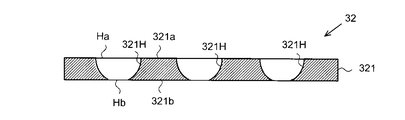
- each mask portion 32 is composed of a nickel-containing metal sheet 321.
- the material constituting the nickel-containing metal sheet 321 is substantially the same as the material constituting the nickel-containing metal sheet 11 in the above-described metal mask substrate 10 for vapor deposition.
- the nickel-containing metal sheet 321 is manufactured by forming the mask hole 321H in the nickel-containing metal sheet 11 described above.
- the nickel-containing metal sheet 321 includes a mask surface 321a and a mask back surface 321b which is a surface opposite to the mask surface 321a. At least one of the mask surface 321a and the mask back surface 321b is the target surface on which the resist layer was located.
- the mask surface 321a is a surface facing the vapor deposition source in the vapor deposition apparatus.
- the mask back surface 321b is a surface that contacts a deposition target such as a glass substrate in the deposition apparatus.
- the surface property of the target surface included in the nickel-containing metal sheet 321 is substantially equal to the surface property of the target surface included in the nickel-containing metal sheet 11.
- the surface texture in the region other than the mask hole 32H in the target surface included in the nickel-containing metal sheet 321 satisfies at least one of [Condition 1] and [Condition 2] described above.
- the mask part 32 has a plurality of mask holes 321H penetrating the nickel-containing metal sheet 321.
- the hole side surface defining the mask hole 321H draws an arc that gently curves from the mask surface 321a toward the mask back surface 321b in a cross-sectional view with respect to the thickness direction of the nickel-containing metal sheet 321.
- the mask surface 321a includes a surface opening Ha that is an opening of the mask hole 321H.
- the mask back surface 321b includes a back surface opening Hb that is an opening of the mask hole 321H.
- the size of the front surface opening Ha is larger than the back surface opening Hb in plan view.
- Each mask hole 321H is a passage through which vapor deposition particles sublimated from the vapor deposition source pass.
- the vapor deposition particles sublimated from the vapor deposition source travel from the front surface opening Ha toward the back surface opening Hb.
- the mask hole 321H in which the front surface opening Ha is larger than the back surface opening Hb can suppress the shadow effect on the vapor deposition particles entering from the front surface opening Ha.
- the mask hole 321H is formed in the nickel-containing metal sheet 11 of the metal mask base material 10 for vapor deposition, on the surface of the base material surface 11a and the base material back surface 11b that has a larger etching amount.
- the size of the opening is larger than the surface with the smaller amount of etching.
- the metal mask 30 for vapor deposition since the front surface opening Ha is larger than the back surface opening Hb, the amount etched on the base material surface 11a can be set larger than the amount etched on the base material back surface 11b. It is.
- the structure whose base-material surface 11a is an object surface is a method of manufacturing the metal mask 30 for vapor deposition, forms a resist mask in the base-material surface 11a, and advances the etching of the nickel containing metal sheet 11 from the base-material surface 11a. It is also possible to adopt a method. As a result, it is possible to suppress light from being scattered on the target surface for positioning the resist mask. Therefore, it is possible to suppress a difference between the resist mask structure formed by exposure and development and the designed resist mask structure. As a result, the structural accuracy of the mask hole 321H of the metal mask 30 for vapor deposition can be increased. In particular, the target surface that satisfies the above [Condition 3] can increase the structural accuracy of the mask hole 321H in a two-dimensional direction on the target surface.
- each mask portion 32 has a plurality of mask holes 321 ⁇ / b> H that penetrate the nickel-containing metal sheet 321. Also in the example illustrated in FIG. 5, the size of the front surface opening Ha is larger than the back surface opening Hb in a plan view.
- Each mask hole 321H includes a mask large hole 32LH having a front surface opening Ha and a mask small hole 32SH having a back surface opening Hb.
- the large mask hole 32LH is a hole whose cross-sectional area monotonously decreases from the front surface opening Ha toward the mask back surface 321b.
- the small mask hole 32SH is a hole whose cross-sectional area monotonously decreases from the back surface opening Hb toward the mask surface 321a.
- the hole side surface that divides each mask hole 321H has a portion where the mask large hole 32LH and the mask small hole 32SH are connected in a cross-sectional view.
- the portion where the large mask hole 32LH and the small mask hole 32SH are connected is located in the middle of the nickel-containing metal sheet 321 in the thickness direction.
- a portion where the large mask hole 32LH and the small mask hole 32SH are connected has a shape protruding toward the inside of the mask hole 321H.
- the distance between the most protruding portion on the side surface of the mask hole 321H and the mask back surface 321b is the step height SH.
- the cross-sectional structure described above with reference to FIG. 4 is an example in which the step height SH is zero.
- the step height SH is zero.
- the mask hole 321H is formed by wet etching from the substrate surface 11a to the substrate back surface 11b, and the wet etching from the substrate back surface 11b is performed.
- the thickness of the nickel-containing metal sheet 11 is preferably 40 ⁇ m or less so that it becomes unnecessary.
- the metal mask base material 10 for vapor deposition produced by (A) electrolysis, (B) rolling and polishing, (C) electrolysis and polishing is preferable.
- the mask large hole 32LH is formed in the nickel-containing metal sheet 11
- a method of proceeding etching of the nickel-containing metal sheet 11 from the substrate surface 11a is adopted.
- the mask small hole 32SH is formed in the nickel-containing metal sheet 11
- a method is adopted in which the etching of the nickel-containing metal sheet 11 is advanced from the substrate back surface 11b.
- the configuration in which the substrate surface 11a is the target surface and the substrate back surface 11b is also the target surface prevents light from being scattered on the target surface for positioning each resist mask. Therefore, the structural accuracy of the mask hole 321H included in the vapor deposition metal mask 30 can be further increased.
- a nickel-containing metal sheet 11 is prepared by (A) electrolysis or (B) rolling and polishing described above (step S1-1).
- a resist layer is formed on one of the target surfaces of the nickel-containing metal sheet 11 (step S1-2), and a resist mask is formed on the target surface by performing exposure and development on the resist layer (step S1-2).
- a mask hole 321H is formed in the nickel-containing metal sheet 11 by wet etching of the target surface using a resist mask (step S1-4).
- the above-described mask portion 32 is manufactured by removing the resist mask from the target surface (step S1-5).
- the above-described metal mask for vapor deposition is manufactured by fixing the mask surface 321a in the plurality of mask portions 32 to the subframe 31 (step S1-6).
- the etching solution for etching the nickel-containing metal sheet 11 may be an acidic etching solution that can etch invar.
- Acidic etchants are, for example, perchloric acid, hydrochloric acid, sulfuric acid, formic acid, and ferric perchlorate solution and a mixture of ferric perchlorate solution and ferric chloride solution.
- the etching of the target surface may be a dip method in which the nickel-containing metal sheet 11 is immersed in an acidic etching solution, or a spray method in which an acidic etching solution is sprayed on the target surface of the nickel-containing metal sheet 11. Also good.
- the target surface may be etched by a spin method in which an acidic etching solution is dropped onto the nickel-containing metal sheet 11 rotated by a spinner.
- the resist layer formed on the target surface may be formed on a target surface after being formed into a sheet shape, or formed by applying a coating liquid for forming a resist layer to the target surface. May be.
- Step S1-5 the steps from Step S1-1 to Step S1-5 described above are performed on the substrate surface 11a corresponding to the mask surface 321a.
- a large mask hole 32LH is formed.
- a resist or the like for protecting the mask large hole 32LH is filled in the mask large hole 32LH.
- the above-described steps S1-2 to S1-5 are performed on the substrate back surface 11b corresponding to the mask back surface 321b, thereby forming the mask small holes 32SH and obtaining the mask portion 32.
- step S1-6 by fixing the mask surface 321a in the plurality of mask portions 32 to the subframe 31, the above-described vapor deposition metal mask is manufactured (step S1-6).
- the support layer 12 is removed from the metal mask base material 10 for vapor deposition after step S1-5.
- the support layer 12 is separated by peeling by laser irradiation, chemical dissolution or peeling, physical peeling, or the like.
- the support layer 12 may be assembled
- the method of chemically removing the support layer 12 is compared with the case where the support layer 12 is physically peeled from the nickel-containing metal sheet 11, no external force acts on the nickel-containing metal sheet 11, and the nickel-containing metal sheet. 11 is suppressed from wrinkling and distortion.
- an alkaline solution that peels the support layer 12 from the nickel-containing metal sheet 11 by using the support layer 12 is used. Is preferred.
- FIG. 7 shows the surface roughness Sa, Sz, the reflectance R, and the reflectance difference at each level of Test Example 1 to Test Example 9.
- FIG. 8 shows the reflectance of each of Test Example 1, Test Example 2, Test Example 3, and Test Example 9 as representative examples among the reflectances measured for each of Test Example 1 to Test Example 9. Shows the dependence of the reflected light angle.
- Test Example 1 As FIG. 7 shows, Test Example 1, Test Example 2, Test Example 3, Test Example 6, and Test Example 7 are the metal mask base material 10 for vapor deposition having a thickness of 20 ⁇ m manufactured by the above (A) electrolysis. It is.
- Test Example 4 and Test Example 5 is a metal mask substrate 10 for vapor deposition having a thickness of 20 ⁇ m manufactured by the above (B) rolling and polishing.
- the metal mask base material 10 for vapor deposition manufactured by said (A) electrolysis shows the surface property of the surface which contact
- the surface roughness Sa of the SUS electrode is 0.018 ⁇ m
- the surface roughness Sz is 0.170 ⁇ m.
- Test Example 8 and Test Example 9 is a metal mask base material 10 for vapor deposition before polishing obtained by rolling, and is a metal mask base material 10 for vapor deposition that has not been polished.
- Each of Test Example 8 and Test Example 9 is thicker than each of Test Example 4 and Test Example 5 by 10 ⁇ m, which is the polishing amount of Test Example 8 and Test Example 9.
- Test Example 1, Test Example 2, Test Example 3, Test Example 6, and Test Example 7 is an aqueous solution to which the following additives are added, and an electrolytic bath adjusted to pH 2.3 is used, and the current density is adjusted. It was obtained by changing in the range of 1 (A / dm 2 ) or more and 4 (A / dm 2 ) or less.
- Test Example 1, Test Example 2, Test Example 3, Test Example 6, and Test Example 7 has different composition ratios of iron and nickel.
- Test Example 8 and Test Example 9 is the nickel-containing metal sheet 11 before polishing in Test Example 4 and Test Example 5 obtained by rolling and polishing, and is a level where chemical polishing is not performed.
- the surface roughness Sa of the target surface was 0.019 ⁇ m or less and the surface roughness Sz of the target surface was 0.308 ⁇ m or less.
- the surface roughness Sa of the target surface is approximately 0.04 ⁇ m, which is manufactured by the above-described (A) electrolysis or (B) polishing. It was confirmed that the surface roughness Sa was greatly reduced in the case of the deposited metal mask substrate for vapor deposition.
- the surface roughness Sz of the target surface is approximately 0.35 ⁇ m or more. Therefore, it was recognized that the surface roughness Sz was reduced in the case of the metal mask substrate for vapor deposition manufactured by the above-described (A) electrolysis or (B) polishing.
- the reflectance R described above was found to be 53.0% or more and 97.0% or less.
- Test Example 8 and Test Example 9 it was recognized that the reflectance R was smaller than 53.0% and had a half width greater than those of other test examples. Accordingly, it was confirmed that a large reflectance R of 53.0% or more can be obtained if the metal mask substrate for vapor deposition manufactured by the above-described (A) electrolysis or (B) polishing.
- the dimension of the minimum resolution of the resist mask formed on each target surface of Test Example 1 to Test Example 7 is within the range of 4 ⁇ m or more and 5 ⁇ m or less when the circular hole is formed in the resist layer by exposure to ultraviolet light. It was observed to disperse. In particular, in each of Test Example 1 to Test Example 3 and Test Example 5 in which the reflectance difference is 3.6% or less, in the two-dimensional direction included in the target surface, compared to Test Example 6 and Test Example 7. It was found that there was little variation in the minimum resolution dimensions. In particular, in each of Test Example 1 to Test Example 3 in which the reflectance difference is 2.5% or less, a smaller dimension than the Test Example 5 in which the reflectance difference is 3.6% or less is the minimum resolution. Obtained.
- the minimum resolution dimension of the resist mask formed by the same manufacturing method on the surfaces of Test Example 8 and Test Example 9 was 7 ⁇ m or more when circular holes were formed in the resist layer by exposure to ultraviolet light. Therefore, from the viewpoint of increasing the structural accuracy of the opening of the metal mask for vapor deposition, the reflectance difference is preferably 3.6% or less, and more preferably 2.5% or less.
- the said embodiment can be changed and implemented as follows. -When manufacturing the metal mask base material for vapor deposition by electrolysis, you may form in advance the pattern used as the mask of the nickel containing metal sheet 11 on the surface of an electrode. In this manufacturing method, the nickel-containing metal sheet 11 is formed in a portion other than the pattern on the surface of the electrode. Then, with the nickel-containing metal sheet 11 formed on the surface of the electrode, the pattern is removed from the surface of the electrode by dissolution or the like, and then the nickel-containing metal sheet is separated from the surface of the electrode. Thereby, the metal mask base material for vapor deposition is manufactured.
- the pattern formed in advance on the surface of the electrode may be a pattern that suppresses the growth of the nickel-containing metal sheet 11 in the pattern, and for example, a resist pattern can be used.
- the object fixed to the subframe 31 can be changed from the mask front surface 321a in the plurality of mask portions 32 to the mask back surface 321b in the plurality of mask portions 32.
- the metal mask for vapor deposition may be a structure in which the mask surface 321 a is fixed to the subframe 31, or may be a structure in which the mask back surface 321 b is fixed to the subframe 31.
- the step of forming the mask large hole 32LH can be changed after the step of forming the mask small hole 32SH.
- SYMBOLS 10 Metal mask base material for vapor deposition, 11,321 ... Nickel containing metal sheet, 11a ... Base material surface, 11b ... Back surface of base material, 12 ... Support layer, 20 ... Mask apparatus, 21H ... Main frame hole, 30 ... For vapor deposition Metal mask, 31 ... subframe, 32 ... mask portion, 321H ... mask hole, 32LH ... mask large hole, 32SH ... mask small hole, 33 ... subframe hole, 321 ... nickel-containing metal sheet, 321a ... mask surface, 321b ... The back of the mask.
Abstract
Description
図1が示すように、蒸着用メタルマスク基材10は、ニッケル含有金属シート11から構成される。ニッケル含有金属シート11は、基材表面11aと、基材表面11aとは反対側の面である基材裏面11bとを備える。基材表面11a、および、基材裏面11bの少なくとも一方は、レジスト層が位置するための対象である対象面である。対象面は、蒸着用メタルマスクが形成される過程において、レジストマスクが形成される面である。 [Metal mask base material for evaporation]
As shown in FIG. 1, the metal
[条件1]表面粗さSa≦0.019μm、かつ、表面粗さSz≦0.308μm。 The surface property of the target surface of the nickel-containing
[Condition 1] Surface roughness Sa ≦ 0.019 μm and surface roughness Sz ≦ 0.308 μm.
表面粗さSa、および、Szは、ISO 25178に準拠する方法によって測定される値である。反射率Rは、ハロゲンランプから射出された光が対象面に入射したときの正反射による反射光の測定を通じ、下記式(1)によって算出される。ハロゲンランプから射出された光は、対象面の法線方向に対して、45°±0.2°の入射角度で対象面における14mm2の領域に入射する。反射光を受光する素子の面積は、11.4mm2である。反射率Rの測定は、対象面のなかで相互に異なる3つの部位に対して行われる。対象面の反射率Rは、対象面の各部位から得られた反射率Rの平均値である。また、各部位における反射率Rの測定は、相互に直交する2つの方向から照射された光を用い、各方向に対して別々に行われる。なお、母材の圧延のみによって形成されたニッケル含有金属シート11を測定の対象とする場合、対象面と対向する方向から見て、対象面に入射する光の方向のいずれかは、母材の圧延された方向と同じである。 [Condition 2] 53.0% ≦ target surface reflectance R ≦ 97.0%.
The surface roughness Sa and Sz are values measured by a method based on ISO 25178. The reflectance R is calculated by the following equation (1) through measurement of reflected light by regular reflection when light emitted from a halogen lamp enters the target surface. The light emitted from the halogen lamp is incident on a 14 mm 2 region on the target surface at an incident angle of 45 ° ± 0.2 ° with respect to the normal direction of the target surface. The area of the element that receives the reflected light is 11.4 mm 2 . The measurement of the reflectance R is performed on three different parts in the target surface. The reflectance R of the target surface is an average value of the reflectance R obtained from each part of the target surface. Moreover, the reflectance R in each part is measured separately for each direction using light emitted from two directions orthogonal to each other. In addition, when the nickel-containing
[正反射による反射光の光量/入射光の光量]×100…(1)
[条件1]および[条件2]の少なくとも一方を満たす表面性状であれば、対象面に照射された光が対象面で散乱することが抑えられる。そして、対象面に位置するレジスト層に光が照射されることに際し、光の一部が対象面で散乱し、散乱した光がレジスト層のなかの露光対象領域以外の部分を照射してしまうことが抑えられる。結果として、露光、および、現像によって形成されるレジストマスクの構造と、設計されたレジストマスクの構造との間の差異を抑えることが可能である。そして、ウェットエッチング法によって形成される開口の構造と、設計された開口の構造との間の差異が生じることを抑えることが可能となる。 Reflectance R =
[Amount of reflected light by regular reflection / amount of incident light] × 100 (1)
If the surface properties satisfy at least one of [Condition 1] and [Condition 2], it is possible to suppress the light irradiated on the target surface from being scattered on the target surface. Then, when light is irradiated to the resist layer located on the target surface, a part of the light is scattered on the target surface, and the scattered light irradiates a portion other than the exposure target region in the resist layer. Is suppressed. As a result, the difference between the resist mask structure formed by exposure and development and the designed resist mask structure can be suppressed. Then, it is possible to suppress a difference between the opening structure formed by the wet etching method and the designed opening structure.
相互に直交する2つの方向は、対象面に含まれる方向である。相互に直交する2つの方向は、第1方向と第2方向とである。相互に直交する2つの方向での反射率差は、第1方向から照射された光における反射率と、第2方向から照射された光における反射率との差である。 [Condition 3] Reflectance difference in two directions orthogonal to each other ≦ 3.6%
Two directions orthogonal to each other are directions included in the target surface. Two directions orthogonal to each other are a first direction and a second direction. The difference in reflectance between two directions orthogonal to each other is a difference between the reflectance of light irradiated from the first direction and the reflectance of light irradiated from the second direction.
蒸着用メタルマスク基材の製造方法は、蒸着用メタルマスクの製造方法に含まれる。蒸着用メタルマスク基材の製造方法は、(A)電解、(B)圧延および研磨、(C)電解および研磨、(D)圧延のみのなかから、いずれか1つが用いられる。 [Method for producing metal mask substrate for vapor deposition]
The manufacturing method of the metal mask base material for vapor deposition is contained in the manufacturing method of the metal mask for vapor deposition. Any one of (A) electrolysis, (B) rolling and polishing, (C) electrolysis and polishing, and (D) rolling is used as the method for producing the metal mask base material for vapor deposition.
ニッケル含有金属シート11の製造方法として電解が用いられる場合、電解に用いられる電極の表面に、ニッケル含有金属シート11が形成される。その後、電極の表面からニッケル含有金属シート11が分離される。それによって、対象面と、対象面とは反対側の面であって電極の表面に接していた面とを備えたニッケル含有金属シート11が製造される。ニッケル含有金属シート11の対象面と同じ程度の表面形態を電極の表面が有している場合、ニッケル含有金属シート11の基材表面11aと基材裏面11bとの両方が、対象面に相当する表面性状を有する。ニッケル含有金属シート11の対象面よりも大きい表面粗さや、ニッケル含有金属シート11よりも低い反射率を電極の表面が有している場合、この電極の表面と接していた面とは反対側の面が、ニッケル含有金属シート11の対象面となる。なお、基材表面11aと基材裏面11bとの両方が対象面に相当する表面性状を有する構成は、対象面にレジスト層を形成することに際して、基材表面11aと基材裏面11bとの区別に要する負荷を軽減することを可能とする。なお、分離されたニッケル含有金属シート11は、分離された後にアニール処理を施されてもよい。 (A) Electrolysis When electrolysis is used as a method for producing the nickel-containing
ニッケル含有金属シート11の製造方法のなかに研磨が用いられる場合、研磨前のニッケル含有金属シート11は、(A)電解によって製造されてもよいし、圧延によって製造されてもよい。研磨前のニッケル含有金属シート11を圧延によって製造する方法は、まず、ニッケル含有金属の母材を圧延し、その後、圧延された母材をアニールする。この際、研磨前のニッケル含有金属シート11における基材表面11aの段差は、母材の表面における段差よりも小さい。また、研磨前のニッケル含有金属シート11における基材裏面11bの段差は、母材の裏面における段差よりも小さい。そして、研磨前のニッケル含有金属シート11のなかで平滑面となる対象面に、物理的、化学的、化学機械的、あるいは、電気的な研磨加工が施される。それによって、対象面を備えたニッケル含有金属シート11が製造される。 (B) Polishing When polishing is used in the manufacturing method of the nickel-containing
図3が示すように、マスク装置20は、メインフレーム21と、複数の蒸着用メタルマスク30とを備える。メインフレーム21は、複数の蒸着用メタルマスク30を支持する枠板状を有する。メインフレーム21は、蒸着を行うための蒸着装置に取り付けられる。メインフレーム21は、複数のメインフレーム孔21Hを有する。各メインフレーム孔21Hは、各蒸着用メタルマスク30が取り付けられる部位のほぼ全体にわたり、メインフレーム21を貫通する。 [Metal mask for evaporation]
As shown in FIG. 3, the
図4で説明した蒸着用メタルマスク30を製造する方法と、図5で説明した蒸着用メタルマスク30を製造する方法とは、ニッケル含有金属シート11にウェットエッチングを行う工程が異なる一方で、それ以外の工程はほぼ同様である。以下では、図4で説明した蒸着用メタルマスク30の製造方法を主に説明し、図5で説明した蒸着用メタルマスク30の製造方法に関しては、その重複した説明を省略する。 [Method of manufacturing metal mask for vapor deposition]
While the method for manufacturing the metal mask for
図7および図8を参照して、上記蒸着用メタルマスク基材10における表面粗さSa,Sz、反射率R、反射率差、および、レジストマスクの加工精度を説明する。図7は、試験例1から試験例9の各水準における表面粗さSa,Szと、反射率Rと、反射率差とを示す。図8は、試験例1から試験例9の各々に対して測定した反射率のなかで、代表的な例となる試験例1、試験例2、試験例3、試験例9の各々の反射率の反射光角度依存性を示す。 [Test example]
With reference to FIGS. 7 and 8, the surface roughness Sa, Sz, reflectance R, reflectance difference, and resist mask processing accuracy in the
・硫酸第一鉄・7水和物 :83.4g
・硫酸ニッケル(II)・6水和物:250.0g
・塩化ニッケル(II)・6水和物:40.0g
・ホウ酸 :30.0g
・サッカリンナトリウム2水和物:2.0g
・マロン酸 :5.2g
・温度 :50℃
試験例4、試験例5の各々は、圧延によって得られた研磨前のニッケル含有金属シート11に、過酸化水素系の化学研磨液を用いた化学的な研磨を施して得られた。 (Electrolytic solution for test example)
・ Ferrous sulfate heptahydrate: 83.4g
Nickel sulfate (II) hexahydrate: 250.0g
Nickel (II) chloride hexahydrate: 40.0 g
・ Boric acid: 30.0 g
・ Saccharin sodium dihydrate: 2.0 g
-Malonic acid: 5.2 g
・ Temperature: 50 ℃
Each of Test Example 4 and Test Example 5 was obtained by subjecting the nickel-containing
・電解による蒸着用メタルマスク基材の製造に際して、ニッケル含有金属シート11のマスクとなるパターンを、電極の表面に予め形成してもよい。この製造方法においては、電極の表面のなかでパターン以外の部分に、ニッケル含有金属シート11が形成される。そして、電極の表面にニッケル含有金属シート11が形成された状態で、電極の表面からパターンが溶解などによって取り除かれ、次いで、電極の表面からニッケル含有金属シートが分離される。これによって、蒸着用メタルマスク基材が製造される。電極の表面に予め形成されるパターンは、そのパターンにおいてニッケル含有金属シート11の成長が抑えられるパターンであればよく、例えばレジストパターンを用いることが可能である。 In addition, the said embodiment can be changed and implemented as follows.
-When manufacturing the metal mask base material for vapor deposition by electrolysis, you may form in advance the pattern used as the mask of the nickel containing
Claims (14)
- 表面と、前記表面とは反対側の面である裏面とを備えるニッケル含有金属シートを含み、
前記表面および前記裏面の少なくとも一方は、レジスト層が位置するための対象面であり、
前記対象面の表面粗さSaが0.019μm以下であり、かつ、前記対象面の表面粗さSzが0.308μm以下である
蒸着用メタルマスク基材。 A nickel-containing metal sheet comprising a front surface and a back surface opposite to the front surface,
At least one of the front surface and the back surface is a target surface on which a resist layer is located,
A metal mask substrate for vapor deposition, wherein the surface roughness Sa of the target surface is 0.019 μm or less, and the surface roughness Sz of the target surface is 0.308 μm or less. - 前記対象面に入射した光の正反射による反射率が53.0%以上97.0%以下である
請求項1に記載の蒸着用メタルマスク基材。 The metal mask base material for vapor deposition of Claim 1. The reflectance by the regular reflection of the light which injected into the said target surface is 53.0% or more and 97.0% or less. - 表面と、前記表面とは反対側の面である裏面とを備えるニッケル含有金属シートを含み、
前記表面および前記裏面の少なくとも一方は、レジスト層が位置するための対象面であり、
前記対象面に入射した光の正反射による反射率が53.0%以上97.0%以下である
蒸着用メタルマスク基材。 A nickel-containing metal sheet comprising a front surface and a back surface opposite to the front surface,
At least one of the front surface and the back surface is a target surface on which a resist layer is located,
The metal mask base material for vapor deposition whose reflectivity by the regular reflection of the light which injected into the said object surface is 53.0% or more and 97.0% or less. - 前記対象面において相互に直交する2つの方向の各々が前記光の入射する方向であり、前記2つの方向における前記反射率の差が3.6%以下である
請求項2または3に記載の蒸着用メタルマスク基材。 4. The vapor deposition according to claim 2, wherein each of two directions orthogonal to each other on the target surface is a direction in which the light is incident, and a difference in reflectance between the two directions is 3.6% or less. Metal mask base material. - 前記ニッケル含有金属シートは、インバーシートである
請求項1から4のいずれか一項に記載の蒸着用メタルマスク基材。 The metal mask substrate for vapor deposition according to any one of claims 1 to 4, wherein the nickel-containing metal sheet is an Invar sheet. - ニッケル含有金属シートから構成されるマスク部を含み、
前記マスク部は、
表面開口を含む表面と、
前記表面開口と連通する裏面開口を含み、前記表面とは反対側の面である裏面とを備え、
前記表面および前記裏面の少なくとも一方が対象面であり、
前記対象面の表面粗さSaが0.019μm以下であり、かつ、前記対象面の表面粗さSzが0.308μm以下である
蒸着用メタルマスク。 Including a mask portion composed of a nickel-containing metal sheet,
The mask portion is
A surface including a surface opening;
Including a back surface opening communicating with the front surface opening, and comprising a back surface that is a surface opposite to the front surface,
At least one of the front surface and the back surface is a target surface;
The metal mask for vapor deposition, wherein the surface roughness Sa of the target surface is 0.019 μm or less, and the surface roughness Sz of the target surface is 0.308 μm or less. - 前記対象面に入射した光の正反射による反射率が53.0%以上97.0%以下である
請求項6に記載の蒸着用メタルマスク。 The metal mask for vapor deposition according to claim 6, wherein a reflectance by regular reflection of light incident on the target surface is 53.0% or more and 97.0% or less. - ニッケル含有金属シートから構成されるマスク部を含み、
前記マスク部は、
表面開口を含む表面と、
前記表面開口と連通する裏面開口を含み、前記表面とは反対側の面である裏面とを備え、
前記表面および前記裏面の少なくとも一方が対象面であり、
前記対象面に入射した光の正反射による反射率が53.0%以上97.0%以下である
蒸着用メタルマスク。 Including a mask portion composed of a nickel-containing metal sheet,
The mask portion is
A surface including a surface opening;
Including a back surface opening communicating with the front surface opening, and comprising a back surface that is a surface opposite to the front surface,
At least one of the front surface and the back surface is a target surface;
A metal mask for vapor deposition, wherein a reflectance by regular reflection of light incident on the target surface is 53.0% or more and 97.0% or less. - 前記対象面において相互に直交する2つの方向の各々が前記光の入射する方向であり、前記2つの方向における前記反射率の差が3.6%以下である
請求項7または8に記載の蒸着用メタルマスク。 The vapor deposition according to claim 7 or 8, wherein each of two directions orthogonal to each other on the target surface is a direction in which the light is incident, and a difference in the reflectance in the two directions is 3.6% or less. Metal mask for use. - 前記対象面は、少なくとも前記表面を含み、
前記表面開口は、蒸着粒子を前記表面開口から前記裏面開口に向けて通すための開口であって、前記裏面開口よりも大きい
請求項6から9のいずれか一項に記載の蒸着用メタルマスク。 The target surface includes at least the surface;
The metal mask for vapor deposition according to any one of claims 6 to 9, wherein the front surface opening is an opening for allowing vapor deposition particles to pass from the front surface opening toward the back surface opening, and is larger than the back surface opening. - 前記ニッケル含有金属シートは、インバーシートである
請求項6から10のいずれか一項に記載の蒸着用メタルマスク。 The metal mask for vapor deposition according to any one of claims 6 to 10, wherein the nickel-containing metal sheet is an Invar sheet. - 電解によって電極面にニッケル含有金属シートを形成することと、
前記電極面から前記ニッケル含有金属シートを分離することとを含み、
前記ニッケル含有金属シートは、表面と、前記表面とは反対側の面である裏面とを備え、
前記表面および前記裏面の少なくとも一方は、レジスト層が位置するための対象面であり、
前記電解は、前記対象面の表面粗さSaを0.019μm以下とし、かつ、前記対象面の表面粗さSzを0.308μm以下とする
蒸着用メタルマスク基材の製造方法。 Forming a nickel-containing metal sheet on the electrode surface by electrolysis;
Separating the nickel-containing metal sheet from the electrode surface,
The nickel-containing metal sheet includes a front surface and a back surface that is a surface opposite to the front surface.
At least one of the front surface and the back surface is a target surface on which a resist layer is located,
The method for producing a metal mask substrate for vapor deposition, wherein the surface roughness Sa of the target surface is 0.019 μm or less and the surface roughness Sz of the target surface is 0.308 μm or less. - 電解によって電極面にニッケル含有金属シートを形成することと、
前記電極面から前記ニッケル含有金属シートを分離することとを含み、
前記ニッケル含有金属シートは、表面と、前記表面とは反対側の面である裏面とを備え、
前記表面および前記裏面の少なくとも一方は、レジスト層が位置するための対象面であり、
前記電解は、前記対象面に入射した光の正反射による反射率を53.0%以上97.0%以下とする
蒸着用メタルマスク基材の製造方法。 Forming a nickel-containing metal sheet on the electrode surface by electrolysis;
Separating the nickel-containing metal sheet from the electrode surface,
The nickel-containing metal sheet includes a front surface and a back surface that is a surface opposite to the front surface.
At least one of the front surface and the back surface is a target surface on which a resist layer is located,
The electrolysis is a method for producing a metal mask substrate for vapor deposition, wherein a reflectance by regular reflection of light incident on the target surface is 53.0% or more and 97.0% or less. - 蒸着用メタルマスク基材の対象面にレジストマスクを形成することと、
前記レジストマスクを用いたウェットエッチングによって前記対象面をエッチングすることとを含み、
前記蒸着用メタルマスク基材が、請求項1から5のいずれか一項に記載の蒸着用メタルマスクである
蒸着用メタルマスクの製造方法。 Forming a resist mask on the target surface of the metal mask substrate for vapor deposition;
Etching the target surface by wet etching using the resist mask,
The said metal mask base material for vapor deposition is the metal mask for vapor deposition as described in any one of Claim 1 to 5. The manufacturing method of the metal mask for vapor deposition.
Priority Applications (7)
| Application Number | Priority Date | Filing Date | Title |
|---|---|---|---|
| JP2016566838A JP6805830B2 (en) | 2015-07-17 | 2016-07-15 | Metal mask base material for vapor deposition, metal mask for vapor deposition, metal mask base material for vapor deposition, and metal mask for vapor deposition |
| DE112016003224.2T DE112016003224T5 (en) | 2015-07-17 | 2016-07-15 | METAL MASK SUBSTRATE FOR STEAM SEPARATION, METAL MASK FOR STEAM SEPARATION, PRODUCTION METHOD FOR METAL MASK SUBSTRATE FOR STEAM DISPOSAL, AND METHOD FOR PRODUCING METAL MASK FOR STEAM SEPARATION |
| CN201680012997.XA CN107406963B (en) | 2015-07-17 | 2016-07-15 | Vapor deposition metal mask substrate and its manufacturing method, vapor deposition metal mask and its manufacturing method |
| KR1020177024435A KR101854584B1 (en) | 2015-07-17 | 2016-07-15 | Metal mask substrate for vapor deposition, metal mask for vapor deposition, production method for metal mask substrate for vapor deposition, and production method for metal mask for vapor deposition |
| KR1020187011823A KR102341452B1 (en) | 2015-07-17 | 2016-07-15 | Metal mask substrate for vapor deposition, metal mask for vapor deposition, production method for metal mask substrate for vapor deposition, and production method for metal mask for vapor deposition |
| US15/786,455 US10876215B2 (en) | 2015-07-17 | 2017-10-17 | Metal mask substrate for vapor deposition, metal mask for vapor deposition, production method for metal mask substrate for vapor deposition, and production method for metal mask for vapor deposition |
| US17/013,535 US11453940B2 (en) | 2015-07-17 | 2020-09-04 | Metal mask substrate for vapor deposition, metal mask for vapor deposition, production method for metal mask substrate for vapor deposition, and production method for metal mask for vapor deposition |
Applications Claiming Priority (6)
| Application Number | Priority Date | Filing Date | Title |
|---|---|---|---|
| JP2015-143509 | 2015-07-17 | ||
| JP2015143509 | 2015-07-17 | ||
| JP2015-171440 | 2015-08-31 | ||
| JP2015171440 | 2015-08-31 | ||
| JP2016-079099 | 2016-04-11 | ||
| JP2016079099 | 2016-04-11 |
Related Child Applications (1)
| Application Number | Title | Priority Date | Filing Date |
|---|---|---|---|
| US15/786,455 Continuation US10876215B2 (en) | 2015-07-17 | 2017-10-17 | Metal mask substrate for vapor deposition, metal mask for vapor deposition, production method for metal mask substrate for vapor deposition, and production method for metal mask for vapor deposition |
Publications (1)
| Publication Number | Publication Date |
|---|---|
| WO2017014172A1 true WO2017014172A1 (en) | 2017-01-26 |
Family
ID=57834346
Family Applications (1)
| Application Number | Title | Priority Date | Filing Date |
|---|---|---|---|
| PCT/JP2016/070951 WO2017014172A1 (en) | 2015-07-17 | 2016-07-15 | Metal mask substrate for vapor deposition, metal mask for vapor deposition, production method for metal mask substrate for vapor deposition, and production method for metal mask for vapor deposition |
Country Status (6)
| Country | Link |
|---|---|
| US (2) | US10876215B2 (en) |
| JP (1) | JP6805830B2 (en) |
| KR (2) | KR102341452B1 (en) |
| CN (2) | CN109440060B (en) |
| DE (1) | DE112016003224T5 (en) |
| WO (1) | WO2017014172A1 (en) |
Cited By (4)
| Publication number | Priority date | Publication date | Assignee | Title |
|---|---|---|---|---|
| JP2019026900A (en) * | 2017-07-31 | 2019-02-21 | 凸版印刷株式会社 | Vapor deposition mask base material, method for manufacturing the same, method for manufacturing vapor deposition mask and method for manufacturing display |
| EP3712295A4 (en) * | 2017-11-14 | 2021-12-15 | Dai Nippon Printing Co., Ltd. | Metal plate for producing vapor deposition masks, inspection method for metal plates, production method for metal plates, vapor deposition mask, vapor deposition mask device, and production method for vapor deposition masks |
| KR20220110313A (en) | 2020-02-05 | 2022-08-05 | 도판 인사츠 가부시키가이샤 | A deposition mask intermediate, a deposition mask, a mask apparatus, and a method for manufacturing a deposition mask |
| US11618940B2 (en) * | 2018-11-05 | 2023-04-04 | Samsung Display Co., Ltd. | Method of manufacturing display apparatus |
Families Citing this family (13)
| Publication number | Priority date | Publication date | Assignee | Title |
|---|---|---|---|---|
| JP6805830B2 (en) | 2015-07-17 | 2020-12-23 | 凸版印刷株式会社 | Metal mask base material for vapor deposition, metal mask for vapor deposition, metal mask base material for vapor deposition, and metal mask for vapor deposition |
| CN107849681A (en) | 2015-07-17 | 2018-03-27 | 凸版印刷株式会社 | The manufacture method of metal mask base material, metal mask and metal mask |
| KR102509663B1 (en) | 2015-07-17 | 2023-03-14 | 도판 인사츠 가부시키가이샤 | Method for producing base for metal masks, method for producing metal mask for vapor deposition, base for metal masks, and metal mask for vapor deposition |
| CN112981319B (en) | 2017-09-15 | 2022-12-20 | 凸版印刷株式会社 | Vapor deposition mask, vapor deposition mask with glass substrate, and mask sheet with glass substrate |
| JP6299922B1 (en) * | 2017-10-13 | 2018-03-28 | 凸版印刷株式会社 | Vapor deposition mask substrate, vapor deposition mask substrate production method, vapor deposition mask production method, and display device production method |
| JP6597920B1 (en) * | 2018-04-11 | 2019-10-30 | 凸版印刷株式会社 | Vapor deposition mask substrate, vapor deposition mask substrate production method, vapor deposition mask production method, and display device production method |
| KR102075064B1 (en) | 2018-11-13 | 2020-02-07 | (주)애니캐스팅 | Multi array electrode arrayed extrusion electrode and method for manufacturing the same |
| KR102109037B1 (en) | 2018-11-13 | 2020-05-11 | (주)애니캐스팅 | Method for manufacturing organic deposition mask using multi array electrode |
| KR20210050306A (en) | 2019-10-28 | 2021-05-07 | (주)애니캐스팅 | Electrochemical machine capable of manufacturing organic deposition mask using multi array electrode |
| KR102339413B1 (en) | 2019-10-28 | 2021-12-14 | (주)애니캐스팅 | Electrochemical machine including electrode module fixing multi array electrode |
| CN110777328A (en) * | 2019-11-21 | 2020-02-11 | 昆山国显光电有限公司 | Mask, evaporation system and preparation method of mask |
| US11085491B1 (en) * | 2020-06-08 | 2021-08-10 | Robert Janian | Self lubricating bearing sleeve |
| TWI772066B (en) * | 2021-06-16 | 2022-07-21 | 達運精密工業股份有限公司 | Method of preparing metal mask substrate |
Citations (8)
| Publication number | Priority date | Publication date | Assignee | Title |
|---|---|---|---|---|
| JPH04162328A (en) * | 1990-10-25 | 1992-06-05 | Yamaha Corp | Manufacture of shadow mask |
| JPH11140667A (en) * | 1997-11-13 | 1999-05-25 | Dainippon Printing Co Ltd | Base material for etching, etching method and etched product |
| JP2002212763A (en) * | 2001-01-22 | 2002-07-31 | Toppan Printing Co Ltd | Method for manufacturing etching parts |
| JP2003213401A (en) * | 2002-01-16 | 2003-07-30 | Sony Corp | Vapor deposition mask and film deposition apparatus |
| JP2005076068A (en) * | 2003-08-29 | 2005-03-24 | Canon Components Inc | Method of producing thin film member by electroforming method |
| JP2009127105A (en) * | 2007-11-27 | 2009-06-11 | Seiko Instruments Inc | Method for manufacturing electroforming component |
| JP2015055007A (en) * | 2013-09-13 | 2015-03-23 | 大日本印刷株式会社 | Metal plate, manufacturing method of metal plate, and manufacturing method of mask using metal plate |
| JP2015129334A (en) * | 2014-01-08 | 2015-07-16 | 大日本印刷株式会社 | Method of manufacturing laminate mask, laminate mask, and laminate mask with protective film |
Family Cites Families (68)
| Publication number | Priority date | Publication date | Assignee | Title |
|---|---|---|---|---|
| US3160752A (en) * | 1963-02-19 | 1964-12-08 | Harold E Bennett | Reflectometer for measuring surface finishes |
| JPS5295410A (en) | 1976-02-04 | 1977-08-11 | Hitachi Ltd | Air spring height control device for vehicles |
| JP2534589B2 (en) | 1991-01-21 | 1996-09-18 | 東洋鋼鈑株式会社 | Polyester resin coated steel plate and original plate for thinned deep drawn can |
| JPH05290724A (en) | 1992-04-10 | 1993-11-05 | Toshiba Corp | Manufacture of shadow mask |
| KR950014366A (en) | 1993-11-27 | 1995-06-16 | 조희재 | Surface treatment device of metal sheet material |
| JP2693943B2 (en) | 1996-01-23 | 1997-12-24 | 富山日本電気株式会社 | Printed wiring board |
| JP3487471B2 (en) | 1996-01-30 | 2004-01-19 | 日立金属株式会社 | Fe-Ni alloy thin plate with excellent etching processability |
| JPH11260255A (en) | 1998-03-05 | 1999-09-24 | Toshiba Corp | Dry film, and manufacture of shadow mask for color picture tube using the same |
| JP2002151841A (en) | 2000-11-13 | 2002-05-24 | Ibiden Co Ltd | Method of manufacturing multilayer printed wiring board |
| JP4134517B2 (en) | 2001-01-22 | 2008-08-20 | 日本軽金属株式会社 | Aluminum foil and method for producing the same |
| JP4390418B2 (en) | 2001-02-14 | 2009-12-24 | Hoya株式会社 | Reflective mask blank for EUV exposure, reflective mask for EUV exposure, and semiconductor manufacturing method |
| DE10206143B4 (en) | 2001-02-14 | 2006-11-16 | Hoya Corp. | Reflective mask blank and reflective mask for EUV exposure and method of making the mask |
| JP4429539B2 (en) | 2001-02-16 | 2010-03-10 | 古河電気工業株式会社 | Electrolytic copper foil for fine pattern |
| TW583688B (en) * | 2002-02-21 | 2004-04-11 | Dainippon Printing Co Ltd | Electromagnetic shielding sheet and method of producing the same |
| KR100813832B1 (en) | 2002-05-31 | 2008-03-17 | 삼성에스디아이 주식회사 | Mask frame assembly for an evaporation and method of manufacturing the same |
| US7314688B2 (en) | 2002-09-11 | 2008-01-01 | Hoya Corporation | Method of producing a reflection mask blank, method of producing a reflection mask, and method of producing a semiconductor device |
| JP2004218034A (en) | 2003-01-17 | 2004-08-05 | Toppan Printing Co Ltd | Method of producing metal mask, and metal mask |
| JP3683261B2 (en) | 2003-03-03 | 2005-08-17 | Hoya株式会社 | REFLECTIVE MASK BLANK HAVING FALSE DEFECT AND MANUFACTURING METHOD THEREOF, REFLECTIVE MASK HAVING FALSE DEFECT AND MANUFACTURING METHOD THEREOF |
| JP3809531B2 (en) | 2003-03-17 | 2006-08-16 | 太陽化学工業株式会社 | Metal mask and metal mask manufacturing method by laser processing method |
| KR100534580B1 (en) | 2003-03-27 | 2005-12-07 | 삼성에스디아이 주식회사 | Deposition mask for display device and Method for fabricating the same |
| WO2005074347A1 (en) * | 2004-01-30 | 2005-08-11 | Dai Nippon Printing Co., Ltd. | Electromagnetic shielding film and method for producing same |
| KR100623158B1 (en) | 2004-11-11 | 2006-09-19 | 엘지마이크론 주식회사 | Metal mask produced using laser beam |
| KR100708654B1 (en) | 2004-11-18 | 2007-04-18 | 삼성에스디아이 주식회사 | Mask assembly and mask frame assembly using the same |
| JP2006233285A (en) | 2005-02-25 | 2006-09-07 | Toray Ind Inc | Vapor deposition mask and method for producing organic el element using the vapor deposition mask |
| JP2007095324A (en) | 2005-09-27 | 2007-04-12 | Hitachi Displays Ltd | Method of manufacturing organic el display panel, and organic el display panel manufactured by this method |
| CN100449038C (en) * | 2005-12-06 | 2009-01-07 | 安泰科技股份有限公司 | Process for preparing invor alloy foil |
| JP2008041553A (en) | 2006-08-09 | 2008-02-21 | Sony Corp | Mask for vapor deposition, and manufacturing method of mask for vapor deposition |
| JP4985227B2 (en) | 2007-08-24 | 2012-07-25 | 大日本印刷株式会社 | Vapor deposition mask, vapor deposition mask device, vapor deposition mask manufacturing method, vapor deposition mask device production method, and vapor deposition mask sheet-like member production method |
| JP5167763B2 (en) | 2007-10-29 | 2013-03-21 | 大日本印刷株式会社 | Vapor deposition mask and vapor deposition mask manufacturing method |
| KR20090065825A (en) * | 2007-12-18 | 2009-06-23 | 엘지디스플레이 주식회사 | Shadow mask and method for fabricating of the same |
| RU2535176C2 (en) | 2009-01-19 | 2014-12-10 | Панасоник Интеллекчуал Проперти Корпорэйшн оф Америка | Encoding method, decoding method, encoding device, decoding device, programme and integrated circuit |
| JP5294072B2 (en) | 2009-03-18 | 2013-09-18 | 日立金属株式会社 | Etching material manufacturing method and etching material |
| JP2011034681A (en) | 2009-07-29 | 2011-02-17 | Hitachi Displays Ltd | Metal processing method, metal mask manufacturing method, and organic el display device manufacturing method |
| JP5367613B2 (en) | 2010-02-12 | 2013-12-11 | Jx日鉱日石金属株式会社 | Copper foil for printed wiring boards |
| CN201864769U (en) * | 2010-04-19 | 2011-06-15 | 潘宇强 | Metal mask plate structure for evaporating color of organic light emitting diode (OLED) display panel |
| JP5636863B2 (en) | 2010-10-18 | 2014-12-10 | 大日本印刷株式会社 | Metal mask and metal mask material |
| EP2444254B1 (en) | 2010-10-22 | 2013-07-10 | Hydro Aluminium Rolled Products GmbH | Aluminum alloy strip for electrochemical roughening and method for producing same |
| JP2012103425A (en) | 2010-11-09 | 2012-05-31 | Panasonic Corp | Manufacturing method for photoelectric composite wiring board, and photoelectric composite wiring board manufactured by the same |
| JP2012158645A (en) | 2011-01-31 | 2012-08-23 | Sumitomo Bakelite Co Ltd | Epoxy resin composition for printed wiring board, prepreg, metal-clad laminate, resin sheet, printed wiring board, and semiconductor device |
| JP5571616B2 (en) | 2011-05-17 | 2014-08-13 | Jx日鉱日石金属株式会社 | Rolled copper foil, and negative electrode current collector, negative electrode plate and secondary battery using the same |
| JP5958804B2 (en) | 2012-03-30 | 2016-08-02 | 株式会社ブイ・テクノロジー | Vapor deposition mask, vapor deposition mask manufacturing method, and organic EL display device manufacturing method |
| CN105789487B (en) | 2012-01-12 | 2019-04-26 | 大日本印刷株式会社 | The manufacturing method of deposition mask and the manufacturing method of organic semiconductor device |
| CN103205680A (en) * | 2012-01-16 | 2013-07-17 | 昆山允升吉光电科技有限公司 | Vapor plating metal mask plate prepared from nickel-iron alloy |
| JP2013245392A (en) | 2012-05-29 | 2013-12-09 | V Technology Co Ltd | Vapor deposition mask and method for manufacturing the same |
| JP5960809B2 (en) | 2012-09-04 | 2016-08-02 | 新日鐵住金株式会社 | Stainless steel sheet for precision machining and manufacturing method thereof |
| JP5721691B2 (en) | 2012-11-20 | 2015-05-20 | Jx日鉱日石金属株式会社 | Metal mask material and metal mask |
| KR101419526B1 (en) * | 2012-12-17 | 2014-07-14 | (재)한국나노기술원 | Manufacturing Method for Surface Texturing of a Light-Emitting Diode and Light-Emitting Diode thereby |
| JP5382259B1 (en) | 2013-01-10 | 2014-01-08 | 大日本印刷株式会社 | Metal plate, method for producing metal plate, and method for producing vapor deposition mask using metal plate |
| JP2014133375A (en) | 2013-01-11 | 2014-07-24 | Sonocom Co Ltd | Screen printing member using electropolishing and method for manufacturing screen printing member |
| JP5534093B1 (en) | 2013-01-11 | 2014-06-25 | 大日本印刷株式会社 | Metal mask and metal mask manufacturing method |
| US9075313B2 (en) * | 2013-03-13 | 2015-07-07 | Taiwan Semiconductor Manufacturing Company, Ltd. | Multiple exposures in extreme ultraviolet lithography |
| JP6142196B2 (en) | 2013-03-15 | 2017-06-07 | 株式会社ブイ・テクノロジー | Manufacturing method of vapor deposition mask |
| JP6403969B2 (en) | 2013-03-29 | 2018-10-10 | Jx金属株式会社 | Copper foil with carrier, printed wiring board, copper-clad laminate, electronic device, and method for manufacturing printed wiring board |
| CN104164647B (en) * | 2013-05-17 | 2018-02-06 | 昆山允升吉光电科技有限公司 | A kind of manufacture craft of mask plate |
| JP6186996B2 (en) * | 2013-07-30 | 2017-08-30 | 旭硝子株式会社 | Reflective mask blank for EUV lithography and reflective mask for EUV lithography |
| JP2015036436A (en) | 2013-08-13 | 2015-02-23 | 大日本印刷株式会社 | Method of producing vapor deposition mask and vapor deposition mask |
| JP6060862B2 (en) | 2013-09-13 | 2017-01-18 | コニカミノルタ株式会社 | Vapor deposition mask, vapor deposition mask manufacturing method, and organic electroluminescent element manufacturing method |
| JP5780350B2 (en) | 2013-11-14 | 2015-09-16 | 大日本印刷株式会社 | Vapor deposition mask, vapor deposition mask with frame, and method of manufacturing organic semiconductor element |
| JP6256000B2 (en) | 2013-12-27 | 2018-01-10 | 大日本印刷株式会社 | Method for manufacturing vapor deposition mask device |
| JP2015127441A (en) | 2013-12-27 | 2015-07-09 | 大日本印刷株式会社 | Manufacturing method of vapor deposition mask device |
| CN104749871B (en) * | 2013-12-30 | 2019-09-03 | 中芯国际集成电路制造(上海)有限公司 | For the mask of reflecting light lithography, production method and its application method |
| JP6357777B2 (en) | 2014-01-08 | 2018-07-18 | 大日本印刷株式会社 | Method for manufacturing laminated mask |
| JP5641462B1 (en) * | 2014-05-13 | 2014-12-17 | 大日本印刷株式会社 | Metal plate, metal plate manufacturing method, and mask manufacturing method using metal plate |
| JP5846279B2 (en) | 2014-10-20 | 2016-01-20 | 大日本印刷株式会社 | Metal mask and metal mask material |
| KR102509663B1 (en) | 2015-07-17 | 2023-03-14 | 도판 인사츠 가부시키가이샤 | Method for producing base for metal masks, method for producing metal mask for vapor deposition, base for metal masks, and metal mask for vapor deposition |
| CN107849681A (en) | 2015-07-17 | 2018-03-27 | 凸版印刷株式会社 | The manufacture method of metal mask base material, metal mask and metal mask |
| JP6805830B2 (en) | 2015-07-17 | 2020-12-23 | 凸版印刷株式会社 | Metal mask base material for vapor deposition, metal mask for vapor deposition, metal mask base material for vapor deposition, and metal mask for vapor deposition |
| JP6759666B2 (en) | 2016-03-31 | 2020-09-23 | 凸版印刷株式会社 | Method for manufacturing photosensitive composition for etching protection and metal processed plate |
-
2016
- 2016-07-15 JP JP2016566838A patent/JP6805830B2/en active Active
- 2016-07-15 CN CN201811311762.8A patent/CN109440060B/en active Active
- 2016-07-15 CN CN201680012997.XA patent/CN107406963B/en active Active
- 2016-07-15 DE DE112016003224.2T patent/DE112016003224T5/en active Pending
- 2016-07-15 KR KR1020187011823A patent/KR102341452B1/en active IP Right Grant
- 2016-07-15 WO PCT/JP2016/070951 patent/WO2017014172A1/en active Application Filing
- 2016-07-15 KR KR1020177024435A patent/KR101854584B1/en active IP Right Grant
-
2017
- 2017-10-17 US US15/786,455 patent/US10876215B2/en active Active
-
2020
- 2020-09-04 US US17/013,535 patent/US11453940B2/en active Active
Patent Citations (8)
| Publication number | Priority date | Publication date | Assignee | Title |
|---|---|---|---|---|
| JPH04162328A (en) * | 1990-10-25 | 1992-06-05 | Yamaha Corp | Manufacture of shadow mask |
| JPH11140667A (en) * | 1997-11-13 | 1999-05-25 | Dainippon Printing Co Ltd | Base material for etching, etching method and etched product |
| JP2002212763A (en) * | 2001-01-22 | 2002-07-31 | Toppan Printing Co Ltd | Method for manufacturing etching parts |
| JP2003213401A (en) * | 2002-01-16 | 2003-07-30 | Sony Corp | Vapor deposition mask and film deposition apparatus |
| JP2005076068A (en) * | 2003-08-29 | 2005-03-24 | Canon Components Inc | Method of producing thin film member by electroforming method |
| JP2009127105A (en) * | 2007-11-27 | 2009-06-11 | Seiko Instruments Inc | Method for manufacturing electroforming component |
| JP2015055007A (en) * | 2013-09-13 | 2015-03-23 | 大日本印刷株式会社 | Metal plate, manufacturing method of metal plate, and manufacturing method of mask using metal plate |
| JP2015129334A (en) * | 2014-01-08 | 2015-07-16 | 大日本印刷株式会社 | Method of manufacturing laminate mask, laminate mask, and laminate mask with protective film |
Cited By (6)
| Publication number | Priority date | Publication date | Assignee | Title |
|---|---|---|---|---|
| JP2019026900A (en) * | 2017-07-31 | 2019-02-21 | 凸版印刷株式会社 | Vapor deposition mask base material, method for manufacturing the same, method for manufacturing vapor deposition mask and method for manufacturing display |
| EP3712295A4 (en) * | 2017-11-14 | 2021-12-15 | Dai Nippon Printing Co., Ltd. | Metal plate for producing vapor deposition masks, inspection method for metal plates, production method for metal plates, vapor deposition mask, vapor deposition mask device, and production method for vapor deposition masks |
| US11237481B2 (en) | 2017-11-14 | 2022-02-01 | Dai Nippon Printing Co., Ltd. | Metal plate for manufacturing deposition mask and manufacturing method for metal plate, and deposition mask and manufacturing method for deposition mask |
| US11733607B2 (en) | 2017-11-14 | 2023-08-22 | Dai Nippon Printing Co., Ltd. | Metal plate for producing vapor deposition masks, inspection method for metal plates, production method for metal plates, vapor deposition mask, vapor deposition mask device, and production method for vapor deposition masks |
| US11618940B2 (en) * | 2018-11-05 | 2023-04-04 | Samsung Display Co., Ltd. | Method of manufacturing display apparatus |
| KR20220110313A (en) | 2020-02-05 | 2022-08-05 | 도판 인사츠 가부시키가이샤 | A deposition mask intermediate, a deposition mask, a mask apparatus, and a method for manufacturing a deposition mask |
Also Published As
| Publication number | Publication date |
|---|---|
| US10876215B2 (en) | 2020-12-29 |
| KR101854584B1 (en) | 2018-05-03 |
| JPWO2017014172A1 (en) | 2018-04-26 |
| US20180038002A1 (en) | 2018-02-08 |
| CN107406963B (en) | 2018-11-20 |
| KR20170104632A (en) | 2017-09-15 |
| KR102341452B1 (en) | 2021-12-21 |
| KR20180049159A (en) | 2018-05-10 |
| CN109440060A (en) | 2019-03-08 |
| CN107406963A (en) | 2017-11-28 |
| CN109440060B (en) | 2021-06-29 |
| US20200399770A1 (en) | 2020-12-24 |
| US11453940B2 (en) | 2022-09-27 |
| DE112016003224T5 (en) | 2018-04-19 |
| JP6805830B2 (en) | 2020-12-23 |
Similar Documents
| Publication | Publication Date | Title |
|---|---|---|
| JP6120038B1 (en) | Method for producing metal mask substrate for vapor deposition | |
| WO2017014172A1 (en) | Metal mask substrate for vapor deposition, metal mask for vapor deposition, production method for metal mask substrate for vapor deposition, and production method for metal mask for vapor deposition | |
| KR101884160B1 (en) | A method for manufacturing a thick metal mask, a method for manufacturing a thick metal mask, | |
| JP7222376B2 (en) | Evaporation mask manufacturing method | |
| JP4955104B2 (en) | Method for forming an electronic circuit | |
| US20200274068A1 (en) | Vapor deposition mask base material, method for manufacturing vapor deposition mask base material, method for manufacturing vapor deposition mask, and method for manufacturing display device | |
| JP7031663B2 (en) | Conductive substrate | |
| JPWO2017130865A1 (en) | Blackening plating solution, manufacturing method of conductive substrate | |
| JPWO2016190224A1 (en) | Blackening plating solution, conductive substrate | |
| JP7003665B2 (en) | Blackening plating solution, manufacturing method of conductive substrate | |
| JP6954345B2 (en) | Conductive substrate, manufacturing method of conductive substrate | |
| JPWO2017130867A1 (en) | Conductive substrate | |
| KR20190073746A (en) | Fe-Ni BASED FOIL HAVING RESIN ADHESION, METHOD FOR PREPARING THE Fe-Ni BASED FOIL, MASK FOR DEPOSITION AND METHOD FOR PREPARING THE MASK | |
| JPWO2017130866A1 (en) | Blackening plating solution, manufacturing method of conductive substrate |
Legal Events
| Date | Code | Title | Description |
|---|---|---|---|
| ENP | Entry into the national phase |
Ref document number: 2016566838 Country of ref document: JP Kind code of ref document: A |
|
| 121 | Ep: the epo has been informed by wipo that ep was designated in this application |
Ref document number: 16827732 Country of ref document: EP Kind code of ref document: A1 |
|
| ENP | Entry into the national phase |
Ref document number: 20177024435 Country of ref document: KR Kind code of ref document: A |
|
| WWE | Wipo information: entry into national phase |
Ref document number: 112016003224 Country of ref document: DE |
|
| 122 | Ep: pct application non-entry in european phase |
Ref document number: 16827732 Country of ref document: EP Kind code of ref document: A1 |