WO2017010028A1 - 燃料ポンプ - Google Patents
燃料ポンプ Download PDFInfo
- Publication number
- WO2017010028A1 WO2017010028A1 PCT/JP2016/002088 JP2016002088W WO2017010028A1 WO 2017010028 A1 WO2017010028 A1 WO 2017010028A1 JP 2016002088 W JP2016002088 W JP 2016002088W WO 2017010028 A1 WO2017010028 A1 WO 2017010028A1
- Authority
- WO
- WIPO (PCT)
- Prior art keywords
- gear
- pump
- fuel
- annular groove
- chamber
- Prior art date
- Legal status (The legal status is an assumption and is not a legal conclusion. Google has not performed a legal analysis and makes no representation as to the accuracy of the status listed.)
- Ceased
Links
Images



Classifications
-
- F—MECHANICAL ENGINEERING; LIGHTING; HEATING; WEAPONS; BLASTING
- F04—POSITIVE - DISPLACEMENT MACHINES FOR LIQUIDS; PUMPS FOR LIQUIDS OR ELASTIC FLUIDS
- F04C—ROTARY-PISTON, OR OSCILLATING-PISTON, POSITIVE-DISPLACEMENT MACHINES FOR LIQUIDS; ROTARY-PISTON, OR OSCILLATING-PISTON, POSITIVE-DISPLACEMENT PUMPS
- F04C2/00—Rotary-piston machines or pumps
- F04C2/08—Rotary-piston machines or pumps of intermeshing-engagement type, i.e. with engagement of co-operating members similar to that of toothed gearing
- F04C2/10—Rotary-piston machines or pumps of intermeshing-engagement type, i.e. with engagement of co-operating members similar to that of toothed gearing of internal-axis type with the outer member having more teeth or tooth-equivalents, e.g. rollers, than the inner member
- F04C2/102—Rotary-piston machines or pumps of intermeshing-engagement type, i.e. with engagement of co-operating members similar to that of toothed gearing of internal-axis type with the outer member having more teeth or tooth-equivalents, e.g. rollers, than the inner member the two members rotating simultaneously around their respective axes
-
- F—MECHANICAL ENGINEERING; LIGHTING; HEATING; WEAPONS; BLASTING
- F02—COMBUSTION ENGINES; HOT-GAS OR COMBUSTION-PRODUCT ENGINE PLANTS
- F02M—SUPPLYING COMBUSTION ENGINES IN GENERAL WITH COMBUSTIBLE MIXTURES OR CONSTITUENTS THEREOF
- F02M37/00—Apparatus or systems for feeding liquid fuel from storage containers to carburettors or fuel-injection apparatus; Arrangements for purifying liquid fuel specially adapted for, or arranged on, internal-combustion engines
- F02M37/04—Feeding by means of driven pumps
- F02M37/041—Arrangements for driving gear-type pumps
-
- F—MECHANICAL ENGINEERING; LIGHTING; HEATING; WEAPONS; BLASTING
- F02—COMBUSTION ENGINES; HOT-GAS OR COMBUSTION-PRODUCT ENGINE PLANTS
- F02M—SUPPLYING COMBUSTION ENGINES IN GENERAL WITH COMBUSTIBLE MIXTURES OR CONSTITUENTS THEREOF
- F02M37/00—Apparatus or systems for feeding liquid fuel from storage containers to carburettors or fuel-injection apparatus; Arrangements for purifying liquid fuel specially adapted for, or arranged on, internal-combustion engines
- F02M37/04—Feeding by means of driven pumps
- F02M37/08—Feeding by means of driven pumps electrically driven
-
- F—MECHANICAL ENGINEERING; LIGHTING; HEATING; WEAPONS; BLASTING
- F04—POSITIVE - DISPLACEMENT MACHINES FOR LIQUIDS; PUMPS FOR LIQUIDS OR ELASTIC FLUIDS
- F04C—ROTARY-PISTON, OR OSCILLATING-PISTON, POSITIVE-DISPLACEMENT MACHINES FOR LIQUIDS; ROTARY-PISTON, OR OSCILLATING-PISTON, POSITIVE-DISPLACEMENT PUMPS
- F04C11/00—Combinations of two or more machines or pumps, each being of rotary-piston or oscillating-piston type; Pumping installations
- F04C11/008—Enclosed motor pump units
-
- F—MECHANICAL ENGINEERING; LIGHTING; HEATING; WEAPONS; BLASTING
- F04—POSITIVE - DISPLACEMENT MACHINES FOR LIQUIDS; PUMPS FOR LIQUIDS OR ELASTIC FLUIDS
- F04C—ROTARY-PISTON, OR OSCILLATING-PISTON, POSITIVE-DISPLACEMENT MACHINES FOR LIQUIDS; ROTARY-PISTON, OR OSCILLATING-PISTON, POSITIVE-DISPLACEMENT PUMPS
- F04C15/00—Component parts, details or accessories of machines, pumps or pumping installations, not provided for in groups F04C2/00 - F04C14/00
-
- F—MECHANICAL ENGINEERING; LIGHTING; HEATING; WEAPONS; BLASTING
- F04—POSITIVE - DISPLACEMENT MACHINES FOR LIQUIDS; PUMPS FOR LIQUIDS OR ELASTIC FLUIDS
- F04C—ROTARY-PISTON, OR OSCILLATING-PISTON, POSITIVE-DISPLACEMENT MACHINES FOR LIQUIDS; ROTARY-PISTON, OR OSCILLATING-PISTON, POSITIVE-DISPLACEMENT PUMPS
- F04C15/00—Component parts, details or accessories of machines, pumps or pumping installations, not provided for in groups F04C2/00 - F04C14/00
- F04C15/0042—Systems for the equilibration of forces acting on the machines or pump
- F04C15/0049—Equalization of pressure pulses
-
- F—MECHANICAL ENGINEERING; LIGHTING; HEATING; WEAPONS; BLASTING
- F04—POSITIVE - DISPLACEMENT MACHINES FOR LIQUIDS; PUMPS FOR LIQUIDS OR ELASTIC FLUIDS
- F04C—ROTARY-PISTON, OR OSCILLATING-PISTON, POSITIVE-DISPLACEMENT MACHINES FOR LIQUIDS; ROTARY-PISTON, OR OSCILLATING-PISTON, POSITIVE-DISPLACEMENT PUMPS
- F04C15/00—Component parts, details or accessories of machines, pumps or pumping installations, not provided for in groups F04C2/00 - F04C14/00
- F04C15/06—Arrangements for admission or discharge of the working fluid, e.g. constructional features of the inlet or outlet
-
- F—MECHANICAL ENGINEERING; LIGHTING; HEATING; WEAPONS; BLASTING
- F04—POSITIVE - DISPLACEMENT MACHINES FOR LIQUIDS; PUMPS FOR LIQUIDS OR ELASTIC FLUIDS
- F04C—ROTARY-PISTON, OR OSCILLATING-PISTON, POSITIVE-DISPLACEMENT MACHINES FOR LIQUIDS; ROTARY-PISTON, OR OSCILLATING-PISTON, POSITIVE-DISPLACEMENT PUMPS
- F04C2/00—Rotary-piston machines or pumps
- F04C2/08—Rotary-piston machines or pumps of intermeshing-engagement type, i.e. with engagement of co-operating members similar to that of toothed gearing
- F04C2/10—Rotary-piston machines or pumps of intermeshing-engagement type, i.e. with engagement of co-operating members similar to that of toothed gearing of internal-axis type with the outer member having more teeth or tooth-equivalents, e.g. rollers, than the inner member
-
- F—MECHANICAL ENGINEERING; LIGHTING; HEATING; WEAPONS; BLASTING
- F02—COMBUSTION ENGINES; HOT-GAS OR COMBUSTION-PRODUCT ENGINE PLANTS
- F02M—SUPPLYING COMBUSTION ENGINES IN GENERAL WITH COMBUSTIBLE MIXTURES OR CONSTITUENTS THEREOF
- F02M37/00—Apparatus or systems for feeding liquid fuel from storage containers to carburettors or fuel-injection apparatus; Arrangements for purifying liquid fuel specially adapted for, or arranged on, internal-combustion engines
- F02M37/04—Feeding by means of driven pumps
- F02M37/08—Feeding by means of driven pumps electrically driven
- F02M37/10—Feeding by means of driven pumps electrically driven submerged in fuel, e.g. in reservoir
-
- F—MECHANICAL ENGINEERING; LIGHTING; HEATING; WEAPONS; BLASTING
- F04—POSITIVE - DISPLACEMENT MACHINES FOR LIQUIDS; PUMPS FOR LIQUIDS OR ELASTIC FLUIDS
- F04C—ROTARY-PISTON, OR OSCILLATING-PISTON, POSITIVE-DISPLACEMENT MACHINES FOR LIQUIDS; ROTARY-PISTON, OR OSCILLATING-PISTON, POSITIVE-DISPLACEMENT PUMPS
- F04C2/00—Rotary-piston machines or pumps
- F04C2/08—Rotary-piston machines or pumps of intermeshing-engagement type, i.e. with engagement of co-operating members similar to that of toothed gearing
- F04C2/082—Details specially related to intermeshing engagement type machines or pumps
- F04C2/086—Carter
-
- F—MECHANICAL ENGINEERING; LIGHTING; HEATING; WEAPONS; BLASTING
- F04—POSITIVE - DISPLACEMENT MACHINES FOR LIQUIDS; PUMPS FOR LIQUIDS OR ELASTIC FLUIDS
- F04C—ROTARY-PISTON, OR OSCILLATING-PISTON, POSITIVE-DISPLACEMENT MACHINES FOR LIQUIDS; ROTARY-PISTON, OR OSCILLATING-PISTON, POSITIVE-DISPLACEMENT PUMPS
- F04C2210/00—Fluid
- F04C2210/20—Fluid liquid, i.e. incompressible
- F04C2210/203—Fuel
-
- F—MECHANICAL ENGINEERING; LIGHTING; HEATING; WEAPONS; BLASTING
- F04—POSITIVE - DISPLACEMENT MACHINES FOR LIQUIDS; PUMPS FOR LIQUIDS OR ELASTIC FLUIDS
- F04C—ROTARY-PISTON, OR OSCILLATING-PISTON, POSITIVE-DISPLACEMENT MACHINES FOR LIQUIDS; ROTARY-PISTON, OR OSCILLATING-PISTON, POSITIVE-DISPLACEMENT PUMPS
- F04C2240/00—Components
- F04C2240/50—Bearings
- F04C2240/54—Hydrostatic or hydrodynamic bearing assemblies specially adapted for rotary positive displacement pumps or compressors
-
- F—MECHANICAL ENGINEERING; LIGHTING; HEATING; WEAPONS; BLASTING
- F04—POSITIVE - DISPLACEMENT MACHINES FOR LIQUIDS; PUMPS FOR LIQUIDS OR ELASTIC FLUIDS
- F04C—ROTARY-PISTON, OR OSCILLATING-PISTON, POSITIVE-DISPLACEMENT MACHINES FOR LIQUIDS; ROTARY-PISTON, OR OSCILLATING-PISTON, POSITIVE-DISPLACEMENT PUMPS
- F04C2240/00—Components
- F04C2240/50—Bearings
- F04C2240/56—Bearing bushings or details thereof
Definitions
- the present disclosure relates to a fuel pump that sucks and discharges fuel into a gear housing chamber.
- Patent Document 1 discloses a pump that sucks and discharges fuel into a gear housing chamber.
- the pump has an outer gear having a plurality of inner teeth, an inner gear having a plurality of outer teeth, which are eccentrically engaged with the outer gear, a cylindrical shape which sandwiches the outer gear and the inner gear from both sides in the axial direction and rotatably accommodates both the gears.
- a pump housing that defines a gear housing chamber is provided. The outer gear and the inner gear rotate while expanding or reducing the volume of a plurality of pump chambers formed between the two gears, so that fluid is sequentially sucked into each pump chamber and then discharged.
- the pump housing has a spiral groove formed from the inner diameter corner portion facing the outer diameter corner portion of the outer gear toward the center portion.
- the spiral groove requires complicated processing, and for example, it is difficult to sufficiently absorb the displacement of the outer gear that may occur when fuel is discharged from the pump chamber, and pulsation is sufficiently suppressed. I could't. As a result, a fuel pump with high pump efficiency could not be provided.
- An object of the present disclosure is to provide a fuel pump with high pump efficiency.
- the fuel pump includes an outer gear having a plurality of inner teeth, an inner gear having a plurality of outer teeth, which are eccentrically engaged with the outer gear, and the outer gear and the inner gear sandwiched from both sides in the axial direction.
- a pump housing that defines a cylindrical gear housing chamber that is rotatably accommodated.
- the outer gear and the inner gear rotate while expanding or reducing the volume of a plurality of pump chambers formed between the two gears, so that fuel is sequentially sucked into each pump chamber and then discharged.
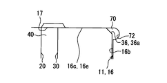
- the pump housing has an inner diameter corner portion facing the outer diameter corner portion in the outer peripheral portion of the outer gear on the inner peripheral portion.
- the pump housing has an annular groove formed in an annular shape over the entire circumference at the inner diameter corner portion.
- the pump housing defines a cylindrical gear receiving chamber.
- the gear accommodating chamber sandwiches the outer gear and the inner gear from both sides in the axial direction, and accommodates both the gears rotatably.
- the outer gear and the inner gear rotate, and the fuel is sequentially sucked into the pump chamber between the two gears and then discharged. For example, during this discharge, a positional deviation such as the outer gear tilting may occur.
- the pump housing has an annular groove formed in an annular shape over the entire circumference at the inner diameter corner portion facing the outer diameter corner portion of the outer gear. If the outer gear is misaligned when fuel flows into the annular groove between both gears and the pump housing, the damper effect caused by the fuel flowing into the annular groove extends to the outer periphery of the outer gear, and the misalignment is corrected. Is done.
- the annular groove can relieve pulsation associated with the rotation of the outer gear and the inner gear, and the outer gear and the inner gear rotate stably, so that sliding resistance is suppressed. As described above, a fuel pump with high pump efficiency can be provided.
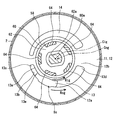
- FIG. 2 is a sectional view taken along line II-II in FIG.
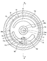
- FIG. 3 is a sectional view taken along line III-III in FIG. 1.
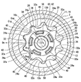
- FIG. 4 is a sectional view taken along line IV-IV in FIG. 1.
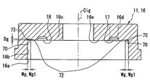
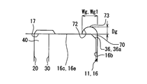
- FIG. 5 is a cross-sectional view showing the pump casing of the first embodiment, taken along the line VV in FIG.
- FIG. 6 is an enlarged view showing a part of the section of FIG. 5 together with an outer gear. It is a front view which shows the joint member in 1st Embodiment. It is a figure corresponding to FIG. 6 in 2nd Embodiment.
- FIG. 7 is a diagram corresponding to FIG. 6 in Modification 1;
- FIG. 7 is a diagram corresponding to FIG. 6 in an example of modification example 2;
- FIG. 10 is a diagram corresponding to FIG. 6 in another example of Modification 2.
- the fuel pump 100 in the first embodiment is a positive displacement trochoid pump, as shown in FIG.
- the fuel pump 100 is a diesel pump that is mounted on a vehicle and used for combustion of an internal combustion engine, and is used for pressure-feeding light oil having a viscosity higher than that of gasoline.
- the fuel pump 100 includes an electric motor 80 and a pump main body 10 housed in a cylindrical pump body 2, and a side cover 5 projecting outward from the opposite side of the pump main body 10 with the electric motor 80 sandwiched in the axial direction Da. Is the main constituent.
- the rotary shaft 80 a of the electric motor 80 is rotationally driven via the electric connector 5 a of the side cover 5.
- the outer gear 30 and the inner gear 20 of the pump body 10 rotate using the driving force of the rotating shaft 80a.
- the light oil as the fuel sucked and pressurized in the gear housing chamber 56 in which both the gears 20 and 30 are housed is discharged from the discharge port 5 b of the side cover 5 through the fuel passage 6 outside the gear housing chamber 56. Is done.
- the electric motor 80 an inner rotor type brushless motor in which magnets are arranged in four poles and coils are formed in six slots is employed.
- the electric motor 80 performs positioning control to rotate the rotary shaft 80a to the drive rotation side or the drive rotation reverse side. Thereafter, drive control is performed to rotate the rotary shaft 80a toward the drive rotation side from the position positioned by the positioning control.
- the drive rotation side indicates a side that is a positive direction (see also FIG. 4) of a rotation direction Rig described later. Further, the reverse side of the drive rotation indicates the side that is the negative direction of the rotation direction Rig (see also FIG. 4).
- the pump body 10 includes a pump housing 11, an inner gear 20, a joint member 60, and an outer gear 30.
- the pump housing 11 has a cylindrical gear that sandwiches the outer gear 30 and the inner gear 20 from both sides in the axial direction Da by overlapping the pump cover 12 and the pump casing 16 in the axial direction Da, and rotatably accommodates both the gears 20 and 30.
- a storage chamber 56 is defined.
- the pump cover 12 shown in FIGS. 1 to 2 and 4 is a component part of the pump housing 11.
- the pump cover 12 is formed in a disk shape having wear resistance by applying a surface treatment such as plating to a base material made of a metal having rigidity such as a steel material.
- the pump cover 12 projects outward from the opposite end of the pump body 2 with the electric motor 80 sandwiched in the axial direction Da.
- the pump cover 12 is formed with a cylindrical suction port 12a and an arc groove-shaped suction passage 13 in order to suck fuel from the outside.
- the suction port 12a passes through a specific opening portion Ss eccentric from the inner center line Cig of the inner gear 20 in the pump cover 12 along the axial direction Da.
- the suction passage 13 is open to the gear housing chamber 56 side of the pump cover 12.
- the inner peripheral edge 13 a of the suction passage 13 extends along the rotational direction Rig of the inner gear 20 to a length of less than a half circumference.
- the outer peripheral edge 13b of the suction passage 13 extends to a length of less than a half circumference along the rotational direction Rog (see also FIG. 4) of the outer gear 30.
- the suction passage 13 is widened from the start end portion 13c toward the end portion 13d in the rotational directions Rig and Rog.
- the suction passage 13 communicates with the suction port 12a by opening the suction port 12a at the opening portion Ss of the groove bottom 13e.
- the width of the suction passage 13 is set to be smaller than the width of the suction port 12a in the entire opening portion Ss where the suction port 12a opens.
- the pump casing 16 shown in FIGS. 1 and 3 to 6 is a component of the pump housing 11.
- the pump casing 16 is formed in a bottomed cylindrical shape having wear resistance by performing a surface treatment such as plating on a base material made of a metal having rigidity such as a steel material.
- the opening 16 a in the pump casing 16 is covered with the pump cover 12, thereby being closed over the entire circumference.
- the inner peripheral portion 22 of the pump casing 16 is formed in a cylindrical hole shape that is eccentric from the inner center line Cig.
- the pump casing 16 has an arc-hole-like discharge passage 17 for discharging fuel from the gear housing chamber 56.
- the discharge passage 17 penetrates the concave bottom portion 16c of the pump casing 16 along the axial direction Da.
- the inner peripheral edge portion 17 a of the discharge passage 17 extends along the rotational direction Rig of the inner gear 20 to a length of less than a half circumference.
- the outer peripheral edge portion 17 b of the discharge passage 17 extends to a length less than a half circumference along the rotation direction Rog of the outer gear 30.
- the discharge passage 17 is reduced in width toward the end portion 17d in the rotational directions Rig and Rog from the start end portion 17c.
- the pump casing 16 has a reinforcing rib 16d in the discharge passage 17.
- the reinforcing rib 16d is formed integrally with the pump casing 16, and is a rib that reinforces the pump casing 16 by straddling the discharge passage 17 in a direction intersecting the rotational direction Rig of the inner gear 20.
- the inner gear 20 slides on the inner peripheral side and the outer gear 30 slides on the outer peripheral side by rotation.
- FIG. 2 a portion of the pump cover 12 that faces the discharge passage 17 across the pump chamber 40 is formed in an arc groove shape corresponding to the shape projected on the axial direction Da.
- the discharge groove 14 is formed.
- the joint accommodation chamber 58 is recessed along the axial direction Da from the sliding surface portion 12b at a position of the pump cover 12 facing the inner gear 20 on the inner center line Cig. In this way, the joint accommodation chamber 58 communicates with the gear accommodation chamber 56 on one side in the axial direction Da with respect to the gear accommodation chamber 56 to rotatably accommodate a main body portion 62 of the joint member 60 described later.
- a radial bearing is provided on the inner center line Cig of the concave bottom portion 16c of the pump casing 16 in order to radially support the rotating shaft 80a of the electric motor 80 that penetrates the concave bottom portion 16c. 50 is fitted and fixed.
- a thrust bearing 52 is fitted and fixed on the inner center line Cig of the pump cover 12 in order to support the rotary shaft 80a in the axial direction Da.
- the pump casing 16 has an inner diameter corner portion 70 at a place where the inner peripheral portion 22 and the sliding surface portion 16e of the concave bottom portion 16c are connected in an annular shape.
- the pump casing 16 has an annular groove 72. That is, the annular groove 72 is formed on the opposite side of the axial direction Da from the joint accommodation chamber 58 with respect to the gear accommodation chamber 56.
- the annular groove 72 is formed in an annular shape over the entire circumference.
- the annular groove 72 of the present embodiment is recessed from the outermost periphery of the recessed bottom portion 16c toward the side opposite to the gear housing chamber 56 in the axial direction Da.
- the bottom 73 of the annular groove 72 is formed in an arc shape in the longitudinal section along the radial direction of the pump casing 16.
- the arc in the present embodiment is elliptical.
- the annular groove 72 is formed so that the width dimension Wg and the depth dimension Dg are substantially constant over the entire circumference.
- the width dimension Wg1 of the portion opened to the gear housing chamber 56 is set to be larger than twice the depth dimension Dg and not more than three times.
- the inner gear 20 and the outer gear 30 are so-called trochoidal gears having respective teeth having trochoidal curves.
- the inner gear 20 shown in FIGS. 1 and 4 is arranged eccentrically in the gear housing chamber 56 by sharing the inner center line Cig with the rotating shaft 80a. Further, the inner gear 20 has a thickness dimension slightly smaller than the corresponding dimension of the cylindrical gear housing chamber 56. In this way, the inner gear 20 has its inner peripheral portion 22 radially supported by the radial bearing 50, and on both sides in the axial direction Da, the sliding surface portion 16e of the pump casing 16 and the sliding surface portion 12b of the pump cover 12, respectively. It is bearing by.
- the inner gear 20 has an insertion hole 26 that is recessed along the axial direction Da at a location facing the joint housing chamber 58.
- a plurality of insertion holes 26 are provided at equal intervals in the circumferential direction, and each insertion hole 26 penetrates to the concave bottom portion 16c side.
- the joint member 60 shown in FIGS. 1, 2, 4 and 7 is formed of a synthetic resin such as polyphenylene sulfide (PPS) resin, for example, and relays the rotating shaft 80a with the inner gear 20, whereby both gears 20, 30 are formed. It is a member which rotates.
- the joint member 60 has a main body portion 62 and an insertion portion 64.
- the main body 62 is fitted through the rotation shaft 80a and the fitting hole 62a.
- a plurality of insertion portions 64 are provided corresponding to each insertion hole 26.
- the insertion hole 26 and the insertion portion 64 of the present embodiment are numbers that avoid the number of poles and slots of the electric motor 80 in order to reduce the influence of torque ripple of the electric motor 80, and are particularly prime numbers. There are 5 each. Each insertion portion 64 extends along the axial direction Da from the outer peripheral side of the fitting hole 62a of the main body 62.
- each insertion hole 26 a corresponding insertion portion 64 is inserted with a gap.
- the insertion portion 64 is pressed against the insertion hole 26, whereby the driving force of the rotary shaft 80a is transmitted to the inner gear 20 via the joint member 60. That is, the inner gear 20 is rotatable in the rotation direction Rig around the inner center line Cig.
- the inner gear 20 has a plurality of external teeth 24 a arranged at equal intervals in the rotation direction Rig on the outer peripheral portion 24.
- Each outer tooth 24a can be opposed to each passage 13, 17 and each groove 14, 18 in the axial direction Da according to the rotation of the inner gear 20, so that sticking to the sliding surface portions 12b, 16e is suppressed. ing.
- the outer gear 30 is arranged coaxially in the gear housing chamber 56 by being eccentric with respect to the inner center line Cig of the inner gear 20.
- the inner gear 20 is eccentric with respect to the outer gear 30 in an eccentric direction De as a radial direction of the outer gear 30.
- the outer gear 30 has an outer diameter and a thickness that are slightly smaller than the corresponding dimensions of the cylindrical gear housing chamber 56.
- the outer gear 30 has its outer peripheral portion 34 supported by the inner peripheral portion 16b of the pump casing 16, and both sides of the axial direction Da are supported by the sliding surface portions 12b and 16e.
- the outer diameter corner portion 36 in the outer peripheral portion 34 of the outer gear 30 and the inner diameter corner portions 70 of the pump housing 11 face each other.
- the outer gear 30 has a chamfered portion 36a having a tapered shape over the entire circumference. With such a configuration, the outer gear 30 is able to rotate in a constant rotational direction Rog around the outer center line Cog that is eccentric from the inner center line Cig in conjunction with the inner gear 20.
- the outer gear 30 has a plurality of internal teeth 32a arranged at equal intervals in the rotation direction Rog in the inner peripheral portion 32.
- the number of the inner teeth 32 a in the outer gear 30 is set to be one more than the number of the outer teeth 24 a in the inner gear 20.
- the number of inner teeth 32a is ten and the number of outer teeth 24a is nine.
- Each inner tooth 32a can be opposed to the passages 13 and 17 and the grooves 14 and 18 in the axial direction Da according to the rotation of the outer gear 30, so that sticking to the sliding surface portions 12b and 16e is suppressed. ing.
- the inner gear 20 meshes with the outer gear 30 by relative eccentricity in the eccentric direction De.
- a plurality of pump chambers 40 are formed between the gears 20 and 30 in the gear housing chamber 56.
- the volume of the pump chamber 40 expands and contracts as the outer gear 30 and the inner gear 20 rotate.
- the volume of the pump chamber 40 increases in the pump chamber 40 that communicates with the suction passage 13 and the suction groove 18.
- fuel is sucked into the pump chamber 40 in the gear housing chamber 56 through the suction passage 13 from the suction port 12a.
- the suction passage 13 is widened from the start end portion 13c toward the end portion 13d (see also FIG. 2), the amount of fuel sucked through the suction passage 13 is the volume expansion amount of the pump chamber 40.
- the suction passage 13 is widened from the start end portion 13c toward the end portion 13d (see also FIG. 2)
- the volume of the pump chamber 40 is reduced in the pump chamber 40 that communicates with the discharge passage 17 and the discharge groove 14.
- fuel is discharged from the pump chamber 40 to the outside of the gear housing chamber 56 through the discharge passage 17.
- the discharge passage 17 is reduced in width toward the end portion 17d from the start end portion 17c (see also FIG. 3), so that the amount of fuel discharged through the discharge passage 17 is reduced in volume of the pump chamber 40. It depends on the amount.
- the fuel that is sequentially sucked into the pump chamber 40 through the suction passage 13 and then discharged through the discharge passage 17 is discharged to the outside through the fuel passage 6 from the discharge port 5b.
- the fuel pressure on the discharge passage 17 side becomes higher than the fuel pressure on the suction passage 13 side by the pump action described above.
- the annular groove 72 communicates a region on the outer peripheral side with respect to the suction passage 13 and a region on the outer peripheral side with respect to the discharge passage 17. Further, by setting the width dimension Wg1 of the annular groove 72 described above, the distance between the pump chamber 40 and the annular groove 72 is optimized, the sealing performance of the pump chamber 40 is ensured, and the fuel flows into the annular groove 72. The amount is adjusted. As a result, in the annular groove 72 into which the fuel has flowed in, a relatively uniform fuel pressure is maintained over the entire circumference.
- one pump chamber 40 formed between the two gears 20 and 30 in the gear housing chamber 56 moves from the suction passage 13 side to the discharge passage 17 side as the two gears 20 and 30 rotate.
- a reaction in which fuel is discharged into the discharge passage 17 acts on the outer gear 30 and the inner gear 20 at the moment when both the gears 20 and 30 reach a predetermined phase and the pump chamber 40 communicates with the discharge passage 17.
- Such counter action may occur the same number of times as the number of teeth of the external teeth 24a per rotation of the inner gear 20 (9 times in the present embodiment).
- the pump housing 11 defines a cylindrical gear housing chamber 56.
- the gear accommodating chamber 56 sandwiches the outer gear 30 and the inner gear 20 from both sides in the axial direction Da, and accommodates both the gears 20 and 30 in a rotatable manner.
- the outer gear 30 and the inner gear 20 rotate, and fuel is sequentially sucked into the pump chamber 40 between the two gears 20 and 30 and then discharged. For example, during this discharge, a positional shift such as the outer gear 30 tilting may occur.
- the pump casing 16 of the pump housing 11 has an annular groove 72 formed in an annular shape over the entire circumference at the inner diameter corner portion 70 facing the outer diameter corner portion 36 of the outer gear 30.
- the damper effect caused by the fuel flowing into the annular groove 72 causes the outer gear 30 to move.
- the misalignment is corrected over the outer periphery.
- Such an annular groove 72 can relieve pulsation associated with the rotation of the outer gear 30 and the inner gear 20, and the outer gear 30 and the inner gear 20 rotate stably, thereby suppressing sliding resistance.
- the fuel pump 100 with high pump efficiency can be provided.
- the annular groove 72 is recessed toward the axial direction Da. According to this, the fuel flowing into the annular groove 72 can exert an operating pressure along the axial direction Da on the outer gear 30 when the position of the outer gear 30 is shifted. Thereby, a damper effect can be efficiently exerted on the outer periphery of the outer gear 30.
- the joint housing chamber 58 that houses the joint member 60 communicates with the gear housing chamber 56 on one side in the axial direction Da with respect to the gear housing chamber 56, and is opposite to the joint housing chamber 58.
- an annular groove 72 is formed on the side.
- the fuel flowing into the joint housing chamber 58 and the fuel flowing into the annular groove 72 exert a damper effect on the outer gear 30 and the inner gear 20 from both sides, so that the balance of the axial direction Da of both the gears 20 and 30 is maintained. It is. Therefore, sliding resistance when both gears 20 and 30 rotate can be reduced. As a result, the pump efficiency is increased.
- the insertion portion 64 extending from the main body portion 62 of the joint member 60 along the axial direction Da is inserted into the insertion hole 26 that is recessed along the axial direction Da in the inner gear 20 with a gap. ing.
- this misalignment can be absorbed by using the gap of the insertion hole 26. Therefore, since the sliding resistance when the outer gear 30 and the inner gear 20 rotate can be reduced, the pump efficiency is increased.
- the bottom 73 of the annular groove 72 has an arcuate cross section.
- Such an annular groove 72 having an arcuate cross section allows the fuel flow at the bottom 73 to flow smoothly, so that the working pressure can be efficiently transmitted to the outer periphery of the outer gear 30.
- the second embodiment is a modification of the first embodiment.
- the second embodiment will be described with a focus on differences from the first embodiment.
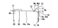
- the annular groove 272 in the fuel pump 200 of the second embodiment is formed in an annular shape over the entire circumference, as in the first embodiment, and from the outermost periphery of the concave bottom portion 16c as shown in FIG. It is recessed toward the opposite side to the gear housing chamber 56 in the axial direction Da.
- the annular groove 272 is formed so that the width dimension Wg and the depth dimension Dg are substantially constant over the entire circumference, but the width in one radial direction becomes smaller toward the bottom 273. It is formed as follows. Specifically, the annular groove 272 of the second embodiment is formed in a triangular section that tapers toward the bottom 273 in a longitudinal section along the radial direction of the pump casing 16. The outer peripheral wall 275 of the annular groove 272 is formed along the axial direction Da, and the inner peripheral wall 274 is inclined toward the outer peripheral side toward the bottom 273. And the bottom part 273 of the annular groove 272 is circular arc-shaped like the first embodiment.
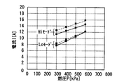
- the results of a comparison experiment between the fuel pump 200 of the present embodiment and the fuel pump of the comparative example in the case where the annular groove 272 is not provided for the fuel pump 200 will be described with reference to FIGS. This will be described below.
- the comparative experiment was conducted under the conditions that the fuel temperature was 25 ° C. and the fuel was JIS No. 2 diesel oil.
- the Hi mode is used when, for example, a full throttle state is used, and the supply voltage to the electric motor 80 is 12V.
- the Lo mode is used, for example, in an idling state, and is when the supply voltage to the electric motor 80 is 6V.
- the fuel pressure in FIGS. 9 and 10 indicates the fuel pressure adjusted in the pressure regulator of the internal combustion engine.
- the data of the fuel pump 200 of the present embodiment is indicated by a solid line
- the data of the comparative example is indicated by a broken line.
- the flow rate of this embodiment exceeds the flow rate of the comparative example at each fuel pressure in each mode.
- the current value of the present embodiment is lower than the current value of the comparative example at each fuel pressure.
- the Lo mode when the fuel pressure is 600 kPa, a significant difference in current value between this embodiment and the comparative example was not recognized, but as the pressure became lower, the current value of this embodiment became the current value of the comparative example. A result below 15 was obtained.
- the pump casing 16 of the pump housing 11 has the annular groove 272 formed in an annular shape over the entire circumference at the inner diameter corner portion 70, so that the first embodiment The effect according to the form can be achieved.
- the annular groove 272 has a triangular cross section that tapers toward the bottom 273. According to this, since the volume of the annular groove 272 can be reduced with respect to the pressure receiving area of the portion where the annular groove 272 faces the outer gear 30, the amount of fuel leakage to the annular groove 272 is suppressed. Meanwhile, the working pressure can be efficiently transmitted to the outer periphery of the outer gear 30.
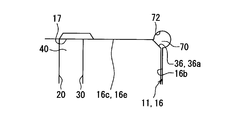
- the annular groove 72 may be formed in a semicircular shape in cross section. Good.
- the width dimension Wg1 is exactly twice the depth dimension Dg.
- the annular groove 72 is recessed in a direction other than the axial direction Da.
- the annular groove 72 in FIG. 12 is recessed in an oblique direction.
- the annular groove 72 in FIG. 13 is recessed in the radial direction. In this configuration, when the position of the outer gear 30 is shifted, it is possible to apply a working pressure along the radial direction to the outer gear 30.
- the bottom 73 of the annular groove 72 may be formed in a rectangular shape.
- the pump housing 11 may have annular grooves 72 formed on both sides of the axial direction Da with respect to the gear housing chamber 56.
- the joint accommodation chamber 58 may not be provided.
- the fuel pump 100 may be a pump that sucks and discharges gasoline other than light oil or liquid fuel based thereon as fuel.
Landscapes
- Engineering & Computer Science (AREA)
- Mechanical Engineering (AREA)
- General Engineering & Computer Science (AREA)
- Chemical & Material Sciences (AREA)
- Combustion & Propulsion (AREA)
- Rotary Pumps (AREA)
- Details And Applications Of Rotary Liquid Pumps (AREA)
Abstract
Description
第1実施形態における燃料ポンプ100は、図1に示すように、容積式のトロコイドポンプである。また、燃料ポンプ100は、車両に搭載され、内燃機関の燃焼に用いる燃料であって、ガソリンよりも粘性の高い軽油を、圧送するために用いられるディーゼルポンプである。燃料ポンプ100は、円筒状のポンプボディ2内部に収容された電動モータ80及びポンプ本体10、並びに電動モータ80を軸方向Daに挟んでポンプ本体10とは反対側から外部に張り出したサイドカバー5を主体として構成されている。こうした燃料ポンプ100では、サイドカバー5の電気コネクタ5aを介した電動モータ80の回転軸80aが回転駆動される。回転軸80aの駆動力を利用して、ポンプ本体10のアウタギヤ30及びインナギヤ20が回転する。これにより、両ギヤ20,30が収容されているギヤ収容室56に吸入及び加圧された燃料としての軽油は、ギヤ収容室56外の燃料通路6を通じて、サイドカバー5の吐出ポート5bから吐出される。
図8~10に示すように、第2実施形態は第1実施形態の変形例である。第2実施形態について、第1実施形態とは異なる点を中心に説明する。
本開示は、上記実施形態に限定して解釈されるものではなく、本開示の要旨を逸脱しない範囲内において種々の実施形態及び組み合わせに適用することができる。
Claims (6)
- 内歯(32a)を複数有するアウタギヤ(30)と、
外歯(24a)を複数有し、前記アウタギヤとは偏心して噛合するインナギヤ(20)と、
前記アウタギヤ及び前記インナギヤを軸方向(Da)両側から挟み、それら両ギヤを回転可能に収容する円筒状のギヤ収容室(56)を画成するポンプハウジング(11)と、を備える燃料ポンプであって、
前記アウタギヤ及び前記インナギヤは、それら両ギヤ間に複数形成されるポンプ室(40)の容積を拡縮させつつ回転することにより、燃料を各前記ポンプ室に順次吸入してから吐出し、
前記ポンプハウジングは、前記アウタギヤの外周部(34)における外径コーナー部(36)と対向する内径コーナー部(70)を内周部(22)に有し、
前記ポンプハウジングは、前記内径コーナー部において、全周に亘って円環状に形成される円環溝(72,272)を有する燃料ポンプ。 - 前記円環溝は、前記軸方向に凹む請求項1に記載の燃料ポンプ。
- 回転駆動する回転軸(80a)と、
前記回転軸を前記インナギヤと中継することで、前記アウタギヤ及び前記インナギヤを回転させるジョイント部材(60)と、を備え、
前記ポンプハウジングは、前記ギヤ収容室に対し、前記軸方向の片側において、前記ギヤ収容室と連通し、前記ジョイント部材を収容するジョイント収容室(58)を有し、
前記円環溝は、前記ギヤ収容室に対し、前記ジョイント収容室とは反対側に形成される請求項1又は2に記載の燃料ポンプ。 - 前記インナギヤは、前記軸方向に沿って凹む挿入穴(26)を有し、
前記ジョイント部材は、
前記ジョイント収容室にて前記回転軸と嵌合する本体部(62)と、
前記本体部から前記軸方向に沿って延伸し、前記挿入穴に隙間をあけて挿入される挿入部(64)と、を有する請求項3に記載の燃料ポンプ。 - 前記円環溝の底部(73,273)は、断面円弧状である請求項1から4のいずれか1項に記載の燃料ポンプ。
- 前記円環溝(272)は、前記円環溝の底部(273)に向かう程先細る断面三角形状である請求項1から5のいずれか1項に記載の燃料ポンプ。
Priority Applications (3)
| Application Number | Priority Date | Filing Date | Title |
|---|---|---|---|
| DE112016003206.4T DE112016003206T5 (de) | 2015-07-16 | 2016-04-19 | Kraftstoffpumpe |
| US15/569,200 US10767645B2 (en) | 2015-07-16 | 2016-04-19 | Fuel pump |
| KR1020177025810A KR101978318B1 (ko) | 2015-07-16 | 2016-04-19 | 연료펌프 |
Applications Claiming Priority (2)
| Application Number | Priority Date | Filing Date | Title |
|---|---|---|---|
| JP2015-142167 | 2015-07-16 | ||
| JP2015142167A JP6418094B2 (ja) | 2015-07-16 | 2015-07-16 | 燃料ポンプ |
Publications (1)
| Publication Number | Publication Date |
|---|---|
| WO2017010028A1 true WO2017010028A1 (ja) | 2017-01-19 |
Family
ID=57757293
Family Applications (1)
| Application Number | Title | Priority Date | Filing Date |
|---|---|---|---|
| PCT/JP2016/002088 Ceased WO2017010028A1 (ja) | 2015-07-16 | 2016-04-19 | 燃料ポンプ |
Country Status (5)
| Country | Link |
|---|---|
| US (1) | US10767645B2 (ja) |
| JP (1) | JP6418094B2 (ja) |
| KR (1) | KR101978318B1 (ja) |
| DE (1) | DE112016003206T5 (ja) |
| WO (1) | WO2017010028A1 (ja) |
Cited By (2)
| Publication number | Priority date | Publication date | Assignee | Title |
|---|---|---|---|---|
| JP2021521049A (ja) * | 2018-04-19 | 2021-08-26 | フィッシャー ダイナミクス ジャーマニー ゲーエムベーハ—Fisher Dynamics Germany Gmbh | 電気モータ、伝動機構、及びスピンドルを備えた自動車用駆動装置 |
| CN116928089A (zh) * | 2022-04-07 | 2023-10-24 | 安徽威灵汽车部件有限公司 | 泵盖、泵装置和车辆 |
Families Citing this family (3)
| Publication number | Priority date | Publication date | Assignee | Title |
|---|---|---|---|---|
| JP6380299B2 (ja) * | 2015-08-26 | 2018-08-29 | 株式会社デンソー | 燃料ポンプ |
| JP6869917B2 (ja) * | 2018-03-28 | 2021-05-12 | 愛三工業株式会社 | 燃料供給装置 |
| US12018680B2 (en) * | 2022-04-12 | 2024-06-25 | Phinia Delphi Luxembourg Sarl | Fluid pump with thrust bearing driver |
Citations (3)
| Publication number | Priority date | Publication date | Assignee | Title |
|---|---|---|---|---|
| JPS61155684U (ja) * | 1985-03-15 | 1986-09-26 | ||
| JP2007085259A (ja) * | 2005-09-22 | 2007-04-05 | Sumitomo Denko Shoketsu Gokin Kk | 内接歯車式ポンプ |
| JP2008038789A (ja) * | 2006-08-08 | 2008-02-21 | Hitachi Powdered Metals Co Ltd | 内接歯車ポンプ |
Family Cites Families (12)
| Publication number | Priority date | Publication date | Assignee | Title |
|---|---|---|---|---|
| JPS61155684A (ja) | 1984-12-28 | 1986-07-15 | Toshiba Corp | ロ−タリ−コンプレツサ |
| US4820138A (en) * | 1987-09-25 | 1989-04-11 | Carter Automotive Company, Inc. | Gear-within-gear fuel pump and method of pressure balancing same |
| JPH05202861A (ja) * | 1991-10-30 | 1993-08-10 | Nippondenso Co Ltd | 歯車式ポンプ |
| JP2002005039A (ja) | 2000-06-27 | 2002-01-09 | Suzuki Motor Corp | トロコイド式オイルポンプ |
| JP2002257052A (ja) * | 2001-03-05 | 2002-09-11 | Denso Corp | トロコイドギヤポンプ |
| JP2007248422A (ja) * | 2006-03-20 | 2007-09-27 | Toshiba Corp | 位置情報提供システム |
| US7563059B2 (en) * | 2006-04-21 | 2009-07-21 | Yg-1 Co., Ltd. | Sinusoidal angled rotary cutting tool |
| JP2008001251A (ja) | 2006-06-23 | 2008-01-10 | Hitachi Ltd | ポンプ装置及びこのポンプ装置が適用されるパワーステアリング装置 |
| JP2009144689A (ja) | 2007-12-18 | 2009-07-02 | Toshiba Corp | 内接ギヤ形ポンプ |
| JP2011032892A (ja) | 2009-07-30 | 2011-02-17 | Daihatsu Motor Co Ltd | トロコイド式回転ポンプ |
| JP2011122548A (ja) | 2009-12-14 | 2011-06-23 | Jtekt Corp | 内接歯車ポンプ |
| JP5909949B2 (ja) | 2011-09-14 | 2016-04-27 | 株式会社ジェイテクト | 内接ギアポンプ |
-
2015
- 2015-07-16 JP JP2015142167A patent/JP6418094B2/ja not_active Expired - Fee Related
-
2016
- 2016-04-19 KR KR1020177025810A patent/KR101978318B1/ko not_active Expired - Fee Related
- 2016-04-19 US US15/569,200 patent/US10767645B2/en not_active Expired - Fee Related
- 2016-04-19 DE DE112016003206.4T patent/DE112016003206T5/de not_active Withdrawn
- 2016-04-19 WO PCT/JP2016/002088 patent/WO2017010028A1/ja not_active Ceased
Patent Citations (3)
| Publication number | Priority date | Publication date | Assignee | Title |
|---|---|---|---|---|
| JPS61155684U (ja) * | 1985-03-15 | 1986-09-26 | ||
| JP2007085259A (ja) * | 2005-09-22 | 2007-04-05 | Sumitomo Denko Shoketsu Gokin Kk | 内接歯車式ポンプ |
| JP2008038789A (ja) * | 2006-08-08 | 2008-02-21 | Hitachi Powdered Metals Co Ltd | 内接歯車ポンプ |
Cited By (4)
| Publication number | Priority date | Publication date | Assignee | Title |
|---|---|---|---|---|
| JP2021521049A (ja) * | 2018-04-19 | 2021-08-26 | フィッシャー ダイナミクス ジャーマニー ゲーエムベーハ—Fisher Dynamics Germany Gmbh | 電気モータ、伝動機構、及びスピンドルを備えた自動車用駆動装置 |
| US11731534B2 (en) | 2018-04-19 | 2023-08-22 | Fisher Dynamics Germany Gmbh | Actuating drive for a motor vehicle, comprising an electronic motor, a transmission, and a spindle |
| JP7391873B2 (ja) | 2018-04-19 | 2023-12-05 | フィッシャー ダイナミクス ジャーマニー ゲーエムベーハ― | 電気モータ、伝動機構、及びスピンドルを備えた自動車用駆動装置 |
| CN116928089A (zh) * | 2022-04-07 | 2023-10-24 | 安徽威灵汽车部件有限公司 | 泵盖、泵装置和车辆 |
Also Published As
| Publication number | Publication date |
|---|---|
| KR20170117527A (ko) | 2017-10-23 |
| DE112016003206T5 (de) | 2018-04-05 |
| US10767645B2 (en) | 2020-09-08 |
| JP6418094B2 (ja) | 2018-11-07 |
| US20180112659A1 (en) | 2018-04-26 |
| KR101978318B1 (ko) | 2019-05-14 |
| JP2017025722A (ja) | 2017-02-02 |
Similar Documents
| Publication | Publication Date | Title |
|---|---|---|
| JP6418094B2 (ja) | 燃料ポンプ | |
| JP6459740B2 (ja) | 流体ポンプ | |
| KR101869836B1 (ko) | 연료 펌프 | |
| JP6380299B2 (ja) | 燃料ポンプ | |
| JP6358159B2 (ja) | 燃料ポンプ | |
| JP6361561B2 (ja) | 流体ポンプ | |
| JP6409673B2 (ja) | 燃料ポンプ | |
| JP6500587B2 (ja) | 燃料ポンプ | |
| JP6299655B2 (ja) | 燃料ポンプ | |
| JP2015052281A5 (ja) | ||
| JP6507998B2 (ja) | 燃料ポンプ | |
| JP6447482B2 (ja) | 燃料ポンプ | |
| JP7689860B2 (ja) | ポンプ装置 | |
| WO2016117316A1 (ja) | 燃料ポンプ及びその製造方法 | |
| JP6361573B2 (ja) | 燃料ポンプ | |
| JP6500455B2 (ja) | 燃料ポンプ | |
| JP6418059B2 (ja) | 燃料ポンプ | |
| JP2007177687A (ja) | タンデム型トロコイドポンプ | |
| JP2006063883A (ja) | 内接歯車式ポンプ |
Legal Events
| Date | Code | Title | Description |
|---|---|---|---|
| 121 | Ep: the epo has been informed by wipo that ep was designated in this application |
Ref document number: 16824014 Country of ref document: EP Kind code of ref document: A1 |
|
| ENP | Entry into the national phase |
Ref document number: 20177025810 Country of ref document: KR Kind code of ref document: A |
|
| WWE | Wipo information: entry into national phase |
Ref document number: 15569200 Country of ref document: US |
|
| WWE | Wipo information: entry into national phase |
Ref document number: 112016003206 Country of ref document: DE |
|
| 122 | Ep: pct application non-entry in european phase |
Ref document number: 16824014 Country of ref document: EP Kind code of ref document: A1 |