WO2017006627A1 - 車両用ペダル装置の後退防止装置 - Google Patents
車両用ペダル装置の後退防止装置 Download PDFInfo
- Publication number
- WO2017006627A1 WO2017006627A1 PCT/JP2016/064687 JP2016064687W WO2017006627A1 WO 2017006627 A1 WO2017006627 A1 WO 2017006627A1 JP 2016064687 W JP2016064687 W JP 2016064687W WO 2017006627 A1 WO2017006627 A1 WO 2017006627A1
- Authority
- WO
- WIPO (PCT)
- Prior art keywords
- vehicle
- pedal
- support shaft
- reverse
- prevention
- Prior art date
- Legal status (The legal status is an assumption and is not a legal conclusion. Google has not performed a legal analysis and makes no representation as to the accuracy of the status listed.)
- Ceased
Links
Images





Classifications
-
- B—PERFORMING OPERATIONS; TRANSPORTING
- B60—VEHICLES IN GENERAL
- B60T—VEHICLE BRAKE CONTROL SYSTEMS OR PARTS THEREOF; BRAKE CONTROL SYSTEMS OR PARTS THEREOF, IN GENERAL; ARRANGEMENT OF BRAKING ELEMENTS ON VEHICLES IN GENERAL; PORTABLE DEVICES FOR PREVENTING UNWANTED MOVEMENT OF VEHICLES; VEHICLE MODIFICATIONS TO FACILITATE COOLING OF BRAKES
- B60T7/00—Brake-action initiating means
- B60T7/02—Brake-action initiating means for personal initiation
- B60T7/04—Brake-action initiating means for personal initiation foot actuated
- B60T7/06—Disposition of pedal
-
- G—PHYSICS
- G05—CONTROLLING; REGULATING
- G05G—CONTROL DEVICES OR SYSTEMS INSOFAR AS CHARACTERISED BY MECHANICAL FEATURES ONLY
- G05G1/00—Controlling members, e.g. knobs or handles; Assemblies or arrangements thereof; Indicating position of controlling members
- G05G1/30—Controlling members actuated by foot
-
- G—PHYSICS
- G05—CONTROLLING; REGULATING
- G05G—CONTROL DEVICES OR SYSTEMS INSOFAR AS CHARACTERISED BY MECHANICAL FEATURES ONLY
- G05G1/00—Controlling members, e.g. knobs or handles; Assemblies or arrangements thereof; Indicating position of controlling members
- G05G1/30—Controlling members actuated by foot
- G05G1/32—Controlling members actuated by foot with means to prevent injury
-
- G—PHYSICS
- G05—CONTROLLING; REGULATING
- G05G—CONTROL DEVICES OR SYSTEMS INSOFAR AS CHARACTERISED BY MECHANICAL FEATURES ONLY
- G05G1/00—Controlling members, e.g. knobs or handles; Assemblies or arrangements thereof; Indicating position of controlling members
- G05G1/30—Controlling members actuated by foot
- G05G1/32—Controlling members actuated by foot with means to prevent injury
- G05G1/327—Controlling members actuated by foot with means to prevent injury means disconnecting the pedal from its hinge or support, e.g. by breaking or bending the support
Definitions
- the present invention relates to a reverse prevention device for a vehicle pedal device that suppresses the operation pedal from moving backward when a dash panel is displaced toward the rear of the vehicle due to a frontal collision of the vehicle.
- Patent Literature 1 and Patent Literature 2 are known as a back-prevention device for a vehicle pedal device that suppresses the operation pedal from moving to the occupant side behind the vehicle body at the time of a forward collision of the vehicle.
- the brake pedal retraction preventing device described in Patent Literature 1 and Patent Literature 2 relates to a vehicle pedal device having a pedal bracket, a brake pedal, an intermediate lever, and a connecting member, and the dash panel is displaced backward toward the driver's seat.
- the step portion of the operation pedal is configured to be prevented from moving backward to the driver's seat side.
- JP 2007-320404 A Japanese Patent Laid-Open No. 2008-204096
- the intermediate lever comes into contact with the vehicle body side member, there is a possibility that a large load due to a frontal collision or the like acts on the vehicle body side member via the intermediate lever or the like, causing the vehicle body side member to be deformed to the vehicle rear side. There is.
- the vehicle body side member is provided with a vehicle steering or the like, if the vehicle body side member is deformed rearward, an occupant (for example, a driver's upper body) is injured. There was a fear.
- the present invention relates to a reverse prevention device for a vehicle pedal device that suppresses the operation pedal from moving backward when a dash panel is displaced to the vehicle rear side due to a frontal collision of the vehicle, and relates to a vehicle body side member toward the vehicle rear side.
- An apparatus for preventing the backward movement of a pedal device for a vehicle that can prevent the deformation of the operational pedal and suppress the backward movement of an operation pedal is provided.
- a vehicular pedal apparatus for preventing a backward movement of a pedal bracket, which is rotatably disposed by a pedal bracket fixed to a dash panel on the front side of the vehicle and a first support shaft of the pedal bracket.
- An operation pedal having a step portion used for stepping on the vehicle and a second support shaft provided in parallel with the first support shaft on the vehicle rear side of the first support shaft so as to be rotatable.
- an intermediate lever for displacing a predetermined output member toward the front of the vehicle by turning in the output direction about the second support shaft, and the stepping operation on the operation pedal by connecting the operation pedal and the intermediate lever.
- An anti-retraction device that suppresses displacement of the stepped portion of the operation pedal toward the rear side of the vehicle, wherein one end portion is rotatably attached to the pedal bracket and is rotated about the second support shaft.
- One end part is attached to the first retreat preventing member supported so as to be able to support the vehicle body side member located on the rear side of the vehicle, and the second retreat is pivotally connected to the first retraction preventing member.
- a connecting position where the first retraction preventing member and the second retraction preventing member are pivotably connected to each other.
- the first retraction preventing member is attached to the pedal bracket. It is located below the reference line connecting 1 attachment position and the 2nd attachment position where the 2nd retreat prevention member is attached to the body side member.
- the reverse prevention device for the vehicle pedal device includes a pedal bracket, an operation pedal, an intermediate lever, and a connecting link. And the reverse prevention apparatus of the said vehicle pedal apparatus can rotate an intermediate
- the reverse preventing device for the vehicle pedal device further includes a first reverse preventing member and a second reverse preventing member, and the first reverse preventing member and the second reverse preventing member are connected to each other. The position is located below the reference line connecting the first attachment position and the second attachment position.
- the reverse preventing device for the vehicle pedal device has the first reverse preventing member and the second reverse moving device.
- the connection position of the prevention member can be moved downward.
- the first retraction preventing member is supported so as to be rotatable about the second support shaft
- the second support shaft also moves downward as the connecting position moves downward.
- the pedal bracket moves downward from the first support shaft.
- the intermediate lever also moves downward together with the second support shaft, the operation pedal rotates to the front side of the vehicle about the first support shaft via the connecting member.
- the reverse preventing device for the vehicle pedal device includes a first reverse preventing member and a second reverse preventing member, and the connection position of the first reverse preventing member and the second reverse preventing member is set to the first position. It is located below the reference line connecting the attachment position and the second attachment position.
- the reverse preventing device for the vehicle pedal device can forcibly rotate the operation pedal and the intermediate lever when the dash panel is displaced to the rear side of the vehicle due to a frontal collision of the vehicle, etc. Therefore, it is possible to suppress the stepped portion of the operation pedal from being displaced toward the rear side of the vehicle.
- the reverse prevention device of the vehicle pedal device the load from the vehicle front side that displaces the dash panel to the vehicle rear side is applied, and the connecting position of the first reverse prevention member and the second reverse prevention member is lowered. It can act in the direction of movement. Therefore, the reverse preventing device for the vehicle pedal device can suppress deformation of the vehicle body side member, and can contribute to reliable protection of the occupant.
- a vehicular pedal device reverse preventing apparatus according to claim 1, wherein the second reverse preventive member is located on the vehicle rear side. One end portion is attached to be detachable from the vehicle body side member when it is quantitatively displaced.
- the second reverse preventing member is detachably attached to one end portion of the vehicle body side member when displaced by a predetermined amount toward the vehicle rear side.
- the reverse preventing device for the vehicle pedal device can exclude the load before the load from the vehicle front side that displaces the dash panel to the vehicle rear side causes the deformation of the vehicle body side member. It can contribute to the reliable protection of passengers.
- the vehicle pedal device reverse preventing device is the vehicle pedal device reverse preventing device according to claim 1 or 2, wherein the second mounting position is the first mounting position. It is characterized by being located above.
- the second mounting position is located above the first mounting position. For this reason, when the dash panel is displaced toward the rear side of the vehicle due to a frontal collision of the vehicle, the reverse prevention device for the vehicle pedal device moves the connection position between the first reverse prevention member and the second reverse prevention member downward. Can be moved reliably. That is, according to the reverse prevention device for the pedal device for a vehicle, it is possible to reliably suppress the stepped portion of the operation pedal from being displaced toward the rear side of the vehicle, and at the same time, it is possible to suppress deformation of the vehicle body side member. As a result, it can contribute to the reliable protection of passengers.
- a vehicular pedal device retreat prevention device according to any one of claims 1 to 3, wherein the vehicular pedal device retreat prevention device is the first attachment position.
- a first distance connecting the connection position and the connection position is longer than a second distance connecting the second attachment position and the connection position.
- the first distance connecting the first attachment position and the connection position is longer than the second distance connecting the second attachment position and the connection position. Therefore, even if the second mounting position is provided in the vertical direction at a position substantially equal to the first mounting position, the dash panel is displaced to the rear side of the vehicle due to a vehicle front collision or the like. Accordingly, the connection position can be reliably moved downward. That is, according to the reverse prevention device for the pedal device for a vehicle, it is possible to reliably suppress the stepped portion of the operation pedal from being displaced toward the rear side of the vehicle, and at the same time, it is possible to suppress deformation of the vehicle body side member. As a result, it can contribute to the reliable protection of passengers.
- a vehicular pedal device retreat prevention device according to any one of claims 1 to 4, wherein the vehicular pedal device retreat prevention device is the first support shaft.
- the operation pedal is rotatably supported with respect to the pedal bracket and the first retraction preventing member is rotatably supported with respect to the pedal bracket.
- the first support shaft rotatably supports the operation pedal with respect to the pedal bracket and rotates the first reverse preventing member with respect to the pedal bracket.
- Support movably. That is, according to the reverse preventing device for the vehicle pedal device, in addition to the function of pivotally supporting the operation pedal with respect to the pedal bracket on the first support shaft, the first reverse with respect to the pedal bracket.
- the prevention member can be pivotally supported, and as a result, the number of parts can be reduced and the manufacturing cost can be reduced.
- a vehicular pedal device retreat prevention device according to any one of claims 1 to 5, wherein the vehicular pedal device retreat prevention device is the second support shaft.
- the intermediate lever and the first retraction preventing member are rotatably supported, and the first retraction preventing member and the second retraction preventing member are rotatably connected. .
- the second support shaft supports the intermediate lever and the first reverse movement prevention member so as to be rotatable relative to each other, and the first reverse movement prevention member and the second rotation prevention member.
- a retreat prevention member is pivotally connected. That is, according to the backward movement prevention device for the vehicle pedal device, in addition to the function of supporting the intermediate lever and the first backward movement prevention member on the second support shaft in a mutually rotatable manner, the first backward movement
- the function of connecting the prevention member and the second retraction prevention member in a pivotable manner can be provided, and as a result, the number of parts can be reduced and the manufacturing cost can be reduced.
- the present invention includes a pedal bracket, an operation pedal, an intermediate lever, and a connecting link, and further includes a first reverse prevention member and a second reverse prevention member.
- the connection position of the first retraction preventing member and the second retraction preventing member is located below a reference line connecting the first attachment position and the second attachment position. Therefore, when the dash panel is displaced toward the rear side of the vehicle, the connecting position of the first reverse prevention member and the second reverse prevention member can be moved downward.
- the operation pedal and the intermediate lever are forcibly rotated along with the downward movement of the connection position, it is possible to suppress the stepped portion of the operation pedal from being displaced to the rear side of the vehicle. Further, by moving the connection position downward, the direction of the load applied from the front side of the vehicle can be changed, so that deformation of the vehicle body side member can be suppressed, and as a result Can contribute to protection.
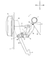
- FIG. 1 is a side view showing a schematic configuration of the brake pedal device 1, and the pedal bracket 10 is shown by an imaginary line (broken line) so that the inner structure thereof can be understood.
- the brake pedal device 1 is fixed to a dash panel P that divides the engine room and the vehicle interior, and includes a pedal bracket 10, an operation pedal 20, an intermediate lever 25, and a connection link 30. And a reverse prevention link 40 and a reverse prevention member 50.
- the brake pedal device 1 generates a braking force on the vehicle by displacing the operating rod R of the brake booster B toward the front side of the vehicle when the operation pedal 20 is rotated by a depression operation of the operation pedal 20. It is configured.
- the brake booster B is integrally fixed to the front side of the dash panel P (that is, the engine room side), and has an operating rod R as an output member.
- the brake booster B doubles the braking force transmitted through the operation pedal 20 and transmits the doubled braking force to the vehicle.
- the operating rod R is disposed so as to protrude from the dash panel P into the vehicle interior on the vehicle rear side, and is configured to be displaceable in the vehicle front-rear direction.
- the instrument panel reinforcement I is disposed on the vehicle rear side (driver's seat side) with respect to the dash panel P, and constitutes a vehicle body side member in the present invention.
- the instrument panel reinforcement I is a pipe-like member having high strength and high rigidity, and is arranged with the vehicle width direction as the longitudinal direction.
- the instrument panel reinforcement I is generally less likely than the dash panel P to be displaced toward the rear of the vehicle when a heavy load is input from the front of the vehicle, such as during a collision.
- a steering shaft (not shown) that constitutes a steering that is a vehicle steering device is fixed to the instrument panel reinforcement I so as to extend from the front side of the dash panel P toward the vehicle interior.
- a slide bracket 60 described later is fixed to the instrument panel reinforcement I, and constitutes a part of the vehicle body side member of the present invention. Details of the slide bracket 60 will be described later with reference to the drawings.
- the pedal bracket 10 is fixed to the passenger compartment side of the dash panel P using bolts or the like, and has a pair of side plates facing each other with a gap in the vehicle width direction.
- the pedal bracket 10 according to the first embodiment has a first support shaft 11.
- the first support shaft 11 is disposed on the pedal bracket 10 so as to extend between the pair of side plates of the pedal bracket 10 so as to be substantially horizontal and substantially parallel to the vehicle width direction.
- the first support shaft 11 rotatably supports the upper portion of the operation pedal 20 with respect to the pedal bracket 10, and one end portion of a retraction preventing link 40 described later on the pedal bracket 10. It fulfills the function of being attached to be rotatable. Therefore, in the first embodiment, the position of the first support shaft 11 functions as the first mounting position in the present invention.
- the second support shaft 12 is disposed on the rear side of the vehicle with respect to the first support shaft 11 so as to extend in parallel with the first support shaft 11.
- the second support shaft 12 rotatably supports the lower portion of the intermediate lever 25 to which the operating rod R is connected, and rotatably supports the other end portion of a reverse preventing link 40 described later.
- the second support shaft 12 according to the first embodiment rotatably supports an end portion of a backward movement preventing member 50, which will be described later, and the backward movement prevention link 40 and the backward movement prevention member 50 can be rotated relative to each other. It is linked to. Therefore, in the first embodiment, the position of the second support shaft 12 functions as a connection position in the present invention.
- the operation pedal 20 is rotatably supported by the first support shaft 11 of the pedal bracket 10 and has a step portion 21 at the lower end. Therefore, the operation pedal 20 rotates around the first support shaft 11 when a stepping operation is performed using the step portion 21. At this time, the step portion 21 moves toward the front side of the vehicle.
- the lower end of the intermediate lever 25 is rotatably supported by the second support shaft 12 disposed on the vehicle rear side with respect to the first support shaft 11, and extends upward.
- An operating rod R is connected to the upper end of the intermediate lever 25 via a clevis. Therefore, when the intermediate lever 25 rotates around the second support shaft 12, the operating rod R can be displaced in the vehicle front-rear direction. That is, according to the brake pedal device 1, the braking force can be generated via the brake booster B by pressing the operating rod R toward the vehicle front side by the intermediate lever 25.
- connection link 30 connects the upper rear portion of the operation pedal 20 and the lower front portion of the intermediate lever 25, and is attached to the operation pedal 20 and the intermediate lever 25 so as to be rotatable. Since one end side of the connection link 30 is connected to the upper rear side portion of the operation pedal 20 via the connection pin 31, the connection link 30 is connected to the operation pedal 20 around the connection pin 31. Can rotate. Further, since the other end side of the connection link 30 is connected to the lower front side portion of the intermediate lever 25 via the connection pin 32, the connection link 30 is connected to the intermediate lever 25 around the connection pin 32. It can rotate with respect to it. Therefore, in the brake pedal device 1, the rotation of the operation pedal 20 around the first support shaft 11 can be transmitted to the intermediate lever 25 via the connection link 30. 2 It can be rotated around the support shaft 12.
- the reverse prevention link 40 is a steel plate member disposed along each side plate of the pedal bracket 10. An end portion on the vehicle front side of the reverse travel prevention link 40 is supported by the first support shaft 11, and an end portion on the vehicle rear side of the reverse travel prevention link 40 is supported by the second support shaft 12.
- the first support shaft 11 is disposed on the pedal bracket 10, while the second support shaft 12 is disposed without the pedal bracket 10. Accordingly, the retraction preventing link 40 can rotate around the first support shaft 11 as the second support shaft 12 moves.
- the retraction preventing link 40 is an example of a first retraction preventing member in the present invention, and fulfills a function of keeping the relative positional relationship (distance) between the first support shaft 11 and the second support shaft 12 constant. Yes.
- the retraction preventing member 50 constitutes a rear portion of the brake pedal device 1 and has a substantially U-shaped cross section. As shown in FIG. 1, the retreat prevention member 50 according to the first embodiment is attached to a slide bracket 60 whose one end constitutes a vehicle body side member. The retraction preventing member 50 is connected to the retraction preventing link 40 via the second support shaft 12 so as to be rotatable.
- the reverse preventing member 50 is an example of a second reverse preventing member according to the present invention, and is detached from the slide bracket 60 constituting the vehicle body side member when a load is applied from the front due to a forward collision of the vehicle. It is attached as follows.
- the slide bracket 60 is fixed to the instrument panel reinforcement I constituting the vehicle body side member, and has a predetermined high rigidity.
- the slide bracket 60 has a substantially U-shaped cross section, and has a slit 61 on a mounting surface to which the retraction preventing member 50 is detachably attached.
- the mounting surface of the slide bracket 60 is inclined downward toward the rear side of the vehicle.
- a slit 61 is formed on the mounting surface of the slide bracket 60.
- the slit 61 is formed to extend along the front-rear direction of the vehicle with a predetermined width, and has a wide portion 62 at the rear end.
- a fixing bolt 51 and a nut 52 are disposed on one surface of the receding prevention member 50 facing the mounting surface of the slide bracket 60.
- the width dimension of the slit 61 is slightly larger than the shaft diameter of the fixing bolt 51 and smaller than the outer diameter of the head of the fixing bolt 51. Therefore, the retraction preventing member 50 can be attached to the slide bracket 60 constituting the vehicle body side member by inserting the fixing bolt 51 through the slit 61 and screwing it with the nut 52.
- the opening dimension of the wide part 62 in the slit 61 is formed larger than the outer diameter of the head in the fixing bolt 51. Accordingly, when the receding prevention member 50 moves relative to the slide bracket 60 and the fixing bolt 51 reaches the wide portion 62 in the slit 61, the fixing bolt 51 and the nut 52 can fall off from the wide portion 62 of the slit 61. .
- the retraction preventing member 50 is maintained attached to the slide bracket 60 constituting the vehicle body side member. To do.
- the locking member 51 and the nut 52 are positioned at the relatively wide portion 62 due to the displacement of the backward movement prevention member 50 toward the vehicle rear side, the backward movement prevention member 50 is detached from the slide bracket 60. Therefore, in the first embodiment, the positions of the fixing bolt 51 and the nut 52 inserted through the slit 61 function as the second mounting position in the present invention.
- the positions of the fixing bolt 51 and the nut 52 functioning as the second attachment position in the present invention are It is located above the first support shaft 11 that functions as the first mounting position in the invention.
- the 2nd support shaft 12 which functions as a connection position in this invention is located below the reference line L which ties a 1st attachment position and a 2nd attachment position. become.
- the step portion 21 is depressed toward the front of the vehicle. For this reason, the operation pedal 20 rotates around the first support shaft 11. At this time, since the upper part of the operation pedal 20 rotates about the first support shaft 11 toward the lower side of the vehicle, the rotation of the operation pedal 20 is transmitted to the intermediate lever 25 via the connection link 30. Is done.
- the connecting link 30 is connected to the lower front portion of the intermediate lever 25 via the connecting pin 32. Therefore, the intermediate lever 25 can rotate about the second support shaft 12 as the operation pedal 20 rotates, and can move the upper portion of the intermediate lever 25 toward the front side of the vehicle.
- the operating rod R of the brake booster B is connected to the upper part of the intermediate lever 25 via a clevis. As a result, the brake pedal device 1 can press the operating rod R in the output direction (the vehicle front side) in conjunction with the stepping operation of the operation pedal 20, and can generate a braking force on the vehicle.
- the second support shaft 12 that functions as a connection position is located below the reference line L.
- the retraction preventing link 40 is formed so as to maintain the relative positional relationship (distance) between the first support shaft 11 and the second support shaft 12.
- the load caused by the rearward displacement of the dash panel P acts to rotate the retraction preventing link 40 downward around the first support shaft 11, and as a result, the second support shaft 12, which is the connection position, moves downward. Displace to
- the position of the fixing bolt 51 or the like that functions as the second mounting position is located above the position of the first support shaft 11 that functions as the first mounting position. For this reason, according to the said brake pedal apparatus 1, the 2nd support shaft 12 which is a connection position can be displaced below more reliably.
- the dash panel P is prevented from moving backward when a predetermined load (for example, the fastening load of the fixing bolt 51 and the nut 52) is exceeded.
- a predetermined load for example, the fastening load of the fixing bolt 51 and the nut 52
- the fixing bolt 51 and the nut 52 of the member 50 move toward the wide portion 62 of the slit 61 (see FIG. 4).
- the fixing bolt 51 and the nut 52 reach the wide portion 62 of the slit 61, the retraction preventing member 50 is detached from the slide bracket 60.
- the brake pedal device 1 can reliably protect the upper body of the passenger in the vehicle interior.
- the brake pedal device 1 includes the pedal bracket 10, the operation pedal 20, the intermediate lever 25, and the connecting link 30.
- the brake pedal device 1 can rotate the intermediate lever 25 via the connecting link 30 in conjunction with the rotation of the operation pedal 20 associated with the stepping operation, so that the operating rod R of the brake booster B is moved to the vehicle. It can be displaced to the front side.
- the brake pedal device 1 further includes a reverse prevention link 40 and a reverse prevention member 50.
- the second support shaft 12 that connects the retraction prevention link 40 and the retraction prevention member 50 is positioned below the reference line L.
- the brake pedal device 1 of the brake pedal device 1 The 2nd support shaft 12 which is a connection position can be moved below (refer FIG. 3, FIG. 4).
- the operation pedal 20 is located on the vehicle front side around the first support shaft 11 via the connection link 30. It will turn to.
- the brake pedal device 1 positions the second support shaft 12, which is a connection position of the reverse movement prevention link 40 and the reverse movement prevention member 50, below the reference line L that connects the first attachment position and the second attachment position.
- the operation pedal 20 and the intermediate lever 25 can be forcibly rotated when the dash panel P is displaced to the rear side of the vehicle due to a frontal collision of the vehicle or the like.
- the said brake pedal apparatus 1 can suppress displacing the step part 21 of the operation pedal 20 to the vehicle rear side as a result (refer FIG. 3, FIG. 4).
- the brake pedal device 1 the load from the vehicle front side that displaces the dash panel P to the vehicle rear side is applied to the second support shaft 12, which is the connection position between the reverse prevention link 40 and the reverse prevention member 50. Since it can be made to act in the direction made to move below, deformation of instrument panel reinforcement I etc. can be controlled. Thereby, the said brake pedal apparatus 1 can suppress the displacement to the vehicle interior of the steering arrange
- the brake pedal device 1 when the reverse prevention member 50 is displaced by a predetermined amount toward the rear side of the vehicle, a slide fixed to the instrument panel reinforcement I that is a vehicle body side member.
- the bracket 60 is detachably attached.
- the position of the fixing bolt 51 or the like that is the second mounting position is located above the first support shaft 11 that functions as the first mounting position. .
- the second support shaft 12, which is the connection position of the reverse prevention link 40 and the reverse prevention member 50 is reliably moved downward. be able to. That is, according to the brake pedal device 1, it is possible to reliably suppress the stepped portion 21 of the operation pedal 20 from being displaced toward the rear side of the vehicle, and at the same time, it is possible to suppress the deformation of the instrument panel reinforcement I. As a result, it can contribute to reliable protection of the upper body of the occupant.
- the first support shaft 11 supports the operation pedal 20 so as to be rotatable with respect to the pedal bracket 10 and prevents the pedal bracket 10 from moving backward.
- the link 40 is rotatably supported. That is, according to the brake pedal device 1, in addition to the function of supporting the operation pedal 20 on the first support shaft 11 so as to be rotatable with respect to the pedal bracket 10, the retraction preventing link 40 is provided with respect to the pedal bracket 10. It is possible to provide a function of supporting the rotation. That is, the brake pedal device 1 can reduce the manufacturing cost by reducing the number of parts.
- the second support shaft 12 supports the intermediate lever 25 and the reverse movement prevention link 40 so as to be rotatable relative to each other, and rotates the reverse movement prevention link 40 and the reverse movement prevention member 50. It is linked movably. That is, according to the brake pedal device 1, in addition to the function of rotatably supporting the intermediate lever 25 and the reverse movement prevention link 40 on the second support shaft 12, the reverse movement prevention link 40 and the backward movement prevention link are provided. It is possible to provide a function of connecting the member 50 so as to be rotatable.
- the brake pedal device 1 can reduce manufacturing costs by reducing the number of parts.
- the brake pedal device 1 according to the second embodiment has the same configuration as the brake pedal device 1 according to the first embodiment described above, except for the configurations of the pedal bracket 10 and the reverse prevention link 40. Therefore, in the following description, the description of the same configuration as that of the first embodiment is omitted, and a different configuration will be described in detail.
- the pedal bracket 10 is fixed to the passenger compartment side of the dash panel P using bolts or the like, and is a pair opposed to each other at an interval in the vehicle width direction. Side plates.
- the pedal bracket 10 has an attachment shaft 13 in addition to the first support shaft 11 similar to that of the first embodiment.
- the first support shaft 11 according to the second embodiment extends between the pair of side plates in the pedal bracket 10 and is substantially horizontal and substantially parallel to the vehicle width direction, so that the upper part of the operation pedal 20 can be rotated. I support it.
- the first support shaft 11 according to the second embodiment is not used to support the end portion of the retraction preventing link 40.
- the 2nd support shaft 12 is arrange
- the second support shaft 12 rotatably supports the lower portion of the intermediate lever 25 to which the operating rod R is connected, and rotatably supports the other end of the retraction preventing link 40.
- the 2nd support shaft 12 which concerns on 2nd Embodiment has connected the link 40 for reverse movement and the reverse movement prevention member 50 so that rotation is mutually possible like the 1st Embodiment, and the connection position in this invention Function as.
- a mounting shaft 13 is formed on the pedal bracket 10 according to the second embodiment.
- the mounting shaft 13 is above the first support shaft 11 and at a position below the mounting position of the receding prevention member 50 with respect to the slide bracket 60 (that is, the position of the fixing bolt 51 etc.). 1 It is arrange
- the attachment shaft 13 has a function of attaching one end portion of the retreat prevention link 40 to the pedal bracket 10 so as to be rotatable, and is a first attachment position in the present invention. It corresponds to.
- the reverse prevention link 40 is a steel plate member disposed along each side plate of the pedal bracket 10 as in the first embodiment.
- An end portion on the vehicle front side of the reverse preventing link 40 is rotatably attached by an attachment shaft 13 of the pedal bracket 10, and an end portion on the vehicle rear side is supported by the second support shaft 12.
- the attachment shaft 13 is disposed on the pedal bracket 10, while the second support shaft 12 is disposed without the pedal bracket 10. Accordingly, the retraction preventing link 40 can rotate around the attachment shaft 13 as the second support shaft 12 moves.
- the positions of the fixing bolt 51 and the nut 52 functioning as the second mounting position in the present invention are It is located above the mounting shaft 13 that functions as the first mounting position in the invention.
- the 2nd support shaft 12 which functions as a connection position in this invention is located below the reference line L which ties a 1st attachment position and a 2nd attachment position. become.
- the second support shaft 12 that functions as a connection position is located below the reference line L, and the reverse prevention link 40 is
- the mounting shaft 13 and the second support shaft 12 are formed to maintain a relative positional relationship (distance).
- the load caused by the rearward displacement of the dash panel P acts to rotate the retraction preventing link 40 downward around the attachment shaft 13.
- the load due to the rearward displacement of the dash panel P displaces the second support shaft 12 that is the connection position downward.
- the position of the fixing bolt 51 or the like that functions as the second mounting position is located above the position of the mounting shaft 13 that functions as the first mounting position. Therefore, according to the brake pedal device 1, the second support shaft 12 that is the connection position can be displaced more reliably downward.
- the intermediate lever 25 when the second support shaft 12 is displaced downward along with the rearward displacement of the dash panel P, the intermediate lever 25 is also moved downward. Due to the movement of the intermediate lever 25, the operation pedal 20 is pulled via the connection link 30 and is forcibly rotated around the first support shaft 11. That is, as shown in FIG. 6, in the brake pedal device 1 according to the second embodiment, the second support shaft 12 that connects the retraction prevention link 40 and the retraction prevention member 50 is displaced downward, thereby operating the operation pedal. 20 and the intermediate lever 25 can be forcibly rotated to prevent the stepped portion 21 of the operation pedal 20 from moving backward toward the driver's seat.
- a predetermined load for example, a fastening load of the fixing bolt 51 and the nut 52
- a predetermined load for example, a fastening load of the fixing bolt 51 and the nut 52
- the brake pedal device 1 according to the second embodiment the load due to the rearward displacement of the dash panel P is removed before the instrument panel reinforcement I that is the vehicle body side member is largely deformed. That is, since the displacement of the steering into the vehicle interior accompanying the deformation of the instrument panel reinforcement I can be suppressed, the brake pedal device 1 according to the second embodiment can also reliably protect the upper body of the passenger in the vehicle interior. it can.
- the brake pedal device 1 includes the pedal bracket 10, the operation pedal 20, the intermediate lever 25, and the connecting link 30, as in the first embodiment. Yes.
- the brake pedal device 1 can rotate the intermediate lever 25 via the connecting link 30 in conjunction with the rotation of the operation pedal 20 accompanying the stepping operation.
- the operating rod R of the brake booster B can be moved. It can be displaced toward the front of the vehicle.
- the brake pedal apparatus 1 which concerns on 2nd Embodiment has the link 40 for a reverse movement, and the reverse movement prevention member 50 similarly to 1st Embodiment.
- the 2nd support shaft 12 which connects the link 40 for a back prevention and the back prevention member 50 is located below the reference line L (refer FIG. 5).
- the brake pedal device 1 suppresses displacement of the stepped portion 21 of the operation pedal 20 toward the vehicle rear side by rotating the operation pedal 20 around the first support shaft 11 toward the vehicle front side. be able to.
- the load from the front side of the vehicle that displaces the dash panel P toward the rear side of the vehicle is the second connecting position of the reverse prevention link 40 and the reverse prevention member 50. It can be made to act in the direction which moves support shaft 12 below, and deformation of instrument panel reinforcement I etc. can be controlled. Thereby, the said brake pedal apparatus 1 can suppress the displacement to the vehicle interior of the steering arrange
- the position of the fixing bolt 51 or the like that is the second mounting position is located above the mounting shaft 13 that functions as the first mounting position. For this reason, when the dash panel P is displaced to the rear side of the vehicle due to a frontal collision of the vehicle or the like, the second support shaft 12, which is the connection position of the reverse prevention link 40 and the reverse prevention member 50, is reliably moved downward. be able to. That is, according to the brake pedal device 1, it is possible to reliably suppress the stepped portion 21 of the operation pedal 20 from being displaced toward the rear side of the vehicle, and at the same time, it is possible to suppress the deformation of the instrument panel reinforcement I. As a result, it can contribute to reliable protection of the upper body of the occupant.
- the second support shaft 12 supports the intermediate lever 25 and the retraction preventing link 40 so as to be rotatable relative to each other, and rotates the retraction preventing link 40 and the retraction preventing member 50. It is linked movably. Therefore, the brake pedal device 1 can reduce the manufacturing cost by reducing the number of parts.
- the brake pedal device 1 according to the third embodiment is the brake pedal device 1 according to the first embodiment and the second embodiment described above, except for the configurations of the pedal bracket 10, the reverse prevention link 40, and the reverse prevention member 50. It has the same composition as. Therefore, in the following description, the description about the same structure as 1st Embodiment and 2nd Embodiment is abbreviate
- the pedal bracket 10 is fixed to the passenger compartment side of the dash panel P by using bolts or the like, and is opposed to each other with a gap in the vehicle width direction. Side plates.
- the pedal bracket 10 has a first support shaft 11 and an attachment shaft 13 as in the second embodiment.
- the first support shaft 11 according to the third embodiment extends between the pair of side plates in the pedal bracket 10 so as to be substantially horizontal and substantially parallel to the vehicle width direction so that the upper part of the operation pedal 20 can be rotated. I support it. As in the second embodiment, the first support shaft 11 according to the third embodiment is not used to support the end portion of the receding prevention link 40.
- the second support shaft 12 supports the lower portion of the intermediate lever 25 in a rotatable manner on the vehicle rear side with respect to the operation pedal 20, and rotates the other end portion of the reverse movement prevention link 40. Supports movable. Further, the second support shaft 12 according to the third embodiment, like the first embodiment and the second embodiment, connects the retraction preventing link 40 and the retraction preventing member 50 so as to be rotatable with respect to each other. It functions as a connection position in the present invention.
- An attachment shaft 13 is formed on the pedal bracket 10 according to the third embodiment.
- the attachment shaft 13 is located above the first support shaft 11 and is attached to the slide bracket 60 at the attachment position (that is, fixed). It is located at the same height as the position of the bolt 51 or the like.
- the attachment shaft 13 has a function of attaching one end portion of the retreat prevention link 40 to the pedal bracket 10 so as to be rotatable, and is a first attachment position in the present invention. It corresponds to.
- the reverse prevention link 40 is a steel plate member disposed along each side plate of the pedal bracket 10 as in the second embodiment. An end portion on the vehicle front side of the reverse prevention link 40 is rotatably attached by an attachment shaft 13 of the pedal bracket 10, and an end portion on the vehicle rear side is supported by the second support shaft 12. .
- the attachment shaft 13 is disposed on the pedal bracket 10, while the second support shaft 12 is disposed without the pedal bracket 10. For this reason, the retraction preventing link 40 can rotate around the attachment shaft 13 as the second support shaft 12 moves.
- the distance between the attachment shaft 13 and the second support shaft 12 positioned at both ends of the retreat prevention link 40 is referred to as a first distance DA.
- the receding prevention member 50 is attached to the slide bracket 60 that constitutes the vehicle body side member, and the second support shaft, as in the first and second embodiments. 12, the retraction preventing link 40 is rotatably connected to the link.
- the reverse prevention member 50 is attached so as to be detached from the slide bracket 60 constituting the vehicle body side member when a load is applied due to a forward collision of the vehicle or the like (see FIG. 2).
- the distance between the second support shaft 12 and the position of the fixing bolt 51 or the like located on one end side of the receding prevention member 50 that is, the mounting position of the receding preventing member 50 with respect to the slide bracket 60). Is called the second distance DB, and the second distance DB is set shorter than the first distance DA described above.
- the positions of the fixing bolt 51 and the nut 52 functioning as the second attachment position in the present invention are It is located at the same height as the mounting shaft 13 that functions as the first mounting position in the invention.
- a reference line L connecting the first attachment position and the second attachment position extends horizontally in the front-rear direction of the vehicle.
- the 2nd support shaft 12 which functions as a connection position in this invention is located below the reference line L which connects a 1st attachment position and a 2nd attachment position. become.
- the first distance DA connecting the mounting shaft 13 that is the first mounting position and the second support shaft 12 that is the connecting position is the fixing bolt that is the second mounting position. It is longer than the second distance DB connecting the position 51 or the like and the second support shaft 12 that is the connecting position (see FIG. 8).
- the second support shaft 12 that functions as a connection position is located below the reference line L, and the retraction preventing link 40 is
- the mounting shaft 13 and the second support shaft 12 are formed to maintain a relative positional relationship (distance).
- the load due to the rearward displacement of the dash panel P acts to rotate the retraction preventing link 40 downward around the attachment shaft 13, and as a result, the second support shaft 12 that is the connecting position is displaced downward. Can be made.
- the position of the fixing bolt 51 or the like that functions as the second mounting position is located at the same height as the position of the mounting shaft 13 that functions as the first mounting position.
- the first distance DA connecting the attachment shaft 13 and the second support shaft 12 is formed longer than the second distance DB connecting the fixing bolt 51 and the second support shaft 12.
- the intermediate lever 25 when the second support shaft 12 is displaced downward with the rearward displacement of the dash panel P, the intermediate lever 25 is also moved downward. Due to the movement of the intermediate lever 25, the operation pedal 20 is pulled via the connection link 30 and is forcibly rotated around the first support shaft 11. That is, as shown in FIG. 9, in the brake pedal device 1 according to the third embodiment, the second support shaft 12 that connects the retraction prevention link 40 and the retraction prevention member 50 is displaced downward, thereby operating the operation pedal. 20 and the intermediate lever 25 can be forcibly rotated to prevent the stepped portion 21 of the operation pedal 20 from moving backward toward the driver's seat.
- a predetermined load for example, a fastening load of the fixing bolt 51 and the nut 52
- the fixing bolt 51 and the like of the receding prevention member 50 move toward the wide portion 62 of the slit 61 (see FIG. 10).
- the receding prevention member 50 is detached from the slide bracket 60.
- the load due to the rearward displacement of the dash panel P is removed before the instrument panel reinforcement I that is the vehicle body side member is largely deformed. That is, since the displacement of the steering into the vehicle interior accompanying the deformation of the instrument panel reinforcement I can be suppressed, the brake pedal device 1 according to the third embodiment can also reliably protect the upper body of the passenger in the vehicle interior. it can.
- the brake pedal device 1 includes the pedal bracket 10, the operation pedal 20, the intermediate lever 25, and the connection link 30, as in the first embodiment. Yes. And the said brake pedal apparatus 1 can rotate the intermediate lever 25 via the connection link 30 in response to rotation of the operation pedal 20 accompanying stepping operation, As a result, the operating rod of the brake booster B R can be displaced toward the front of the vehicle.
- the brake pedal apparatus 1 which concerns on 3rd Embodiment has the link 40 for a reverse movement, and the reverse movement prevention member 50 similarly to 1st Embodiment and 2nd Embodiment,
- the 2nd support shaft 12 which connects the retreat prevention member 50 is located below the reference line L (refer FIG. 8).
- the operation pedal 20 is pulled through the connection link 30, so that the operation pedal 20 is located on the vehicle front side with the first support shaft 11 as the center. It is possible to suppress the stepped portion 21 of the operation pedal 20 from being displaced toward the rear side of the vehicle.
- the load from the front side of the vehicle that displaces the dash panel P toward the rear side of the vehicle is the second connecting position between the reverse prevention link 40 and the reverse prevention member 50. It can be made to act in the direction which moves support shaft 12 below.
- the brake pedal device 1 can suppress deformation of the instrument panel reinforcement I and the like.
- the said brake pedal apparatus 1 can suppress the displacement to the vehicle interior of the steering arrange
- the reverse prevention member 50 is detachably attached to the slide bracket 60 that is a vehicle body side member when the vehicle is displaced by a predetermined amount toward the vehicle rear side.
- the positions of the fixing bolts 51 and the like that are the second attachment positions are located at the same height as the attachment shaft 13 that functions as the first attachment position.
- the first distance DA connecting the mounting shaft 13 and the second support shaft 12 that is the connecting position is longer than the second distance DB connecting the position of the fixing bolt 51 and the second support shaft 12.
- the second support shaft 12 supports the intermediate lever 25 and the retraction preventing link 40 so as to be rotatable relative to each other, and rotates the retraction preventing link 40 and the retraction preventing member 50. It is linked movably. Therefore, the brake pedal device 1 can reduce the manufacturing cost by reducing the number of parts.
- the present invention has been described above based on the embodiments. However, the present invention is not limited to the above-described embodiments, and various improvements and modifications can be made without departing from the spirit of the present invention.
- the second support shaft 12 that is the rotation shaft of the intermediate lever 25 is used to connect the retraction prevention link 40 and the retraction prevention member 50 to each other so as to be rotatable.
- the present invention is not limited to this mode, and a configuration in which the retraction preventing link 40 and the retraction preventing member 50 are connected to each other so as to be rotatable may be provided separately from the second support shaft 12.
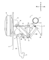
- the corner portion of the retraction preventing link 40 formed in a substantially L shape in a side view is rotatably supported by the second support shaft 12, and the front end portion thereof is The pedal bracket 10 is attached to the attachment shaft 13 so as to be rotatable.
- the rear end portion of the reverse preventing link 40 having a substantially L shape and the reverse preventing member 50 are connected to each other by the connecting shaft 14 so as to be rotatable. That is, in the case shown in FIG. 11, the connecting shaft 14 functions as a connecting position according to the present invention and is positioned below the reference line L.
- the brake pedal device 1 when the dash panel P is displaced to the rear side of the vehicle and the distance between the dash panel P and the instrument panel reinforcement I and the like is reduced, the brake pedal device 1 is connected to the connecting shaft 14 which is the connecting position. Is moved downward. As the connecting shaft 14 moves downward, the retraction preventing link 40 also moves downward, so that the intermediate lever 25 also moves downward together with the second support shaft 12. Accordingly, since the operation pedal 20 is pulled downward via the connection link 30, the brake pedal device 1 rotates the operation pedal 20 to the vehicle front side around the first support shaft 11. Thus, displacement of the stepped portion 21 of the operation pedal 20 toward the vehicle rear side can be suppressed.
- the brake pedal device 1 can suppress deformation of the instrument panel reinforcement I and the like. Thereby, the said brake pedal apparatus 1 can suppress the displacement to the vehicle interior of the steering arrange
- the detachment structure of the receding prevention member 50 with respect to the slide bracket 60 is formed in the slide bracket 60, the slit 61 having the wide portion 62, the fixing bolt 51 attached to the receding prevention member 50, and
- the receding prevention member 50 may be attached to the slide bracket 60 by using a rivet that breaks when a predetermined or greater detachment load is applied.
- the mounting shaft formed on the receding prevention member 50 is configured to be held by a holding hole formed on the slide bracket 60, and an opening width smaller than the outer diameter of the mounting shaft on the vehicle rear side in the holding hole. You may form the opening which has. In this case, when the backward movement preventing member 50 is displaced by a predetermined amount toward the rear side of the vehicle, the mounting shaft can be moved to the outside of the holding hole through the opening, so that the backward movement preventing member 50 is detached from the slide bracket 60. Can be made.
- each structural member can be changed suitably.
- the shape of each constituent member is not limited to the shape of each constituent member of the brake pedal device 1 in the above-described embodiment.
- the shape of each constituent member is changed to avoid interference between the constituent members. May be.
Landscapes
- Engineering & Computer Science (AREA)
- Physics & Mathematics (AREA)
- General Physics & Mathematics (AREA)
- Automation & Control Theory (AREA)
- Transportation (AREA)
- Mechanical Engineering (AREA)
- Braking Elements And Transmission Devices (AREA)
- Mechanical Control Devices (AREA)
Abstract
ダッシュパネルが車両後側へ変位した場合に、車両後方側への車体側部材の変形と共に、操作ペダルの後退を抑制可能な車両用ペダル装置の後退防止装置を提供する。ブレーキペダル装置1は、ペダルブラケット10と、操作ペダル20と、中間レバー25と、連結リンク30と、後退防止用リンク40と、後退防止部材50を有している。後退防止用リンク40と後退防止部材50とを連結する第2支持軸12は、基準線Lよりも下方に位置している為、車両の前方衝突があった場合、ブレーキペダル装置1は、第2支持軸12を下方へ移動させる。これにより、中間レバー25も第2支持軸12と共に下方に移動する為、操作ペダル20は、連結リンク30を介して、第1支持軸11まわりに車両前方側へ回動する。車両前方側からの荷重を、第2支持軸12を下方へ移動させる方向に作用させる為、インパネリインフォースメントI等の変形を抑制し得る。
Description
本発明は、車両の前方衝突に伴ってダッシュパネルが車両後側へ変位した場合に、操作ペダルが後退することを抑制する車両用ペダル装置の後退防止装置に関する。
従来、車両の前方衝突時に操作ペダルが車体後方の乗員側に移動することを抑制する車両用ペダル装置の後退防止装置として、例えば、特許文献1、特許文献2記載の発明が知られている。特許文献1、特許文献2記載のブレーキペダル後退防止装置は、ペダルブラケットと、ブレーキペダルと、中間レバーと、連結部材を有する車両用ペダル装置に関し、ダッシュパネルが運転席側へ後退変位させられた際に前記操作ペダルの踏部がその運転席側へ後退することを抑制するように構成されている。
具体的に説明すると、特許文献1記載のブレーキペダル装置は、ダッシュパネルが後退変位させられると、車両後方側の車体側部材としてのステアリングメンバ及び衝突用インパクトブラケットに、中間レバーに相当する回動レバーを接触させて、当該回動レバーを回動させるように構成されている。そして、特許文献1記載のブレーキペダル装置は、車体側部材との当接による回動レバーの回動に伴って、ペダルアームを車両前方側に回動させて、ブレーキペダルの後退を抑制している。
又、特許文献2記載の車両用ペダル支持構造においても、ダッシュパネルが後退変位させられた場合、車両後方側の車体側部材としてのインパネリインフォース及びサブペダルブラケットに、中間レバーに相当する第1リンクを接触させて、当該第1リンクを回動させるように構成されている。そして、特許文献2記載の車両用ペダル支持構造においても、車体側部材との当接に基づく第1リンクの回動に伴って、ペダルアームを車両前方側に回動させて、ブレーキペダルの後退を抑制している。
ここで、近年においては、車両における広い車室スペースの確保が重要視されており、ダッシュパネルの前方部分(例えば、エンジンルーム)と、車体側部材(例えば、インパネリインフォース)との間隔が狭まる傾向にある。
特許文献1、2記載の発明のように、操作ペダルの後退防止を実現する上で、中間レバーと車体側部材との接触を条件とする場合、ダッシュパネルの前方部分(例えば、エンジンルーム)と、車体側部材(例えば、インパネリインフォース)との間隔が狭まると、適正な状態で操作ペダルの後退防止機能を実現できない場合が生じ得る。
又、中間レバーが車体側部材と接触する関係上、前方衝突等に伴う大荷重が、中間レバー等を介して車体側部材に作用し、車体側部材を車両後方側へ変形させてしまう可能性がある。一般的に、車体側部材には、車両のステアリング等が配設されている為、車体側部材が後方側へ変形してしまった場合、乗員(例えば、運転者の上半身)を負傷させてしまう虞があった。
本発明は、車両の前方衝突に伴ってダッシュパネルが車両後側へ変位した場合に、操作ペダルが後退することを抑制する車両用ペダル装置の後退防止装置に関し、車両後方側への車体側部材の変形を防止すると共に、操作ペダルの後退を抑制可能な車両用ペダル装置の後退防止装置を提供する。
本発明の一側面に係る車両用ペダル装置の後退防止装置は、車両前側のダッシュパネルに固定されたペダルブラケットと、前記ペダルブラケットの第1支持軸によって回動可能に配設され、車両前側への踏込み操作に用いられる踏部を有する操作ペダルと、前記第1支持軸よりも車両後方側において、当該第1支持軸に平行に設けられた第2支持軸まわりに回動可能に支持されると共に、前記第2支持軸を軸とした出力方向への回動によって、所定の出力部材を車両前側へ変位させる中間レバーと、前記操作ペダルと前記中間レバーを連結し、前記操作ペダルに対する踏込み操作に連動して、前記中間レバーを前記出力方向へ回動させる連結リンクと、を有する車両用ペダル装置に関し、前記ダッシュパネルが車両後側へ変位した場合に、前記操作ペダルの踏部の車両後側への変位を抑制する後退防止装置であって、前記ペダルブラケットに対して一端部が回動可能に取り付けられると共に、前記第2支持軸を中心として回動可能に支持された第1後退防止部材と、車両後方側に位置する車体側部材に対して一端部が取り付けられると共に、前記第1後退防止部材に対して回動可能に連結された第2後退防止部材と、を有し、前記第1後退防止部材と前記第2後退防止部材を回動可能に連結した連結位置は、前記ペダルブラケットに対して前記第1後退防止部材が取り付けられている第1取付位置と、前記車体側部材に対して前記第2後退防止部材が取り付けられている第2取付位置とを結ぶ基準線よりも下方に位置していることを特徴とする。
当該車両用ペダル装置の後退防止装置は、ペダルブラケットと、操作ペダルと、中間レバーと、連結リンクと、を有している。そして、当該車両用ペダル装置の後退防止装置は、踏込み操作に伴う操作ペダルの回動に連動して、連結リンクを介して中間レバーを回動させることができ、結果的に、出力部材を車両前側へ変位させ得る。ここで、当該車両用ペダル装置の後退防止装置は、更に、第1後退防止部材と、第2後退防止部材とを有しており、前記第1後退防止部材と前記第2後退防止部材の連結位置は、第1取付位置と第2取付位置とを結ぶ基準線よりも下方に位置している。これにより、当該車両用ペダル装置の後退防止装置は、前記ダッシュパネルが車両後側へ変位し、ダッシュパネルと車体側部材との間隔が狭まっていくと、前記第1後退防止部材と第2後退防止部材の連結位置を下方へ移動させることができる。ここで、第1後退防止部材は、前記第2支持軸を中心として回動可能に支持されている為、連結位置が下方に移動することに伴い、第2支持軸も下方に移動していき、ペダルブラケットの第1支持軸よりも下方へ移動していく。この結果、中間レバーも第2支持軸と共に下方に移動する為、操作ペダルは、連結部材を介して、第1支持軸を中心として車両前方側へ回動することになる。
即ち、当該車両用ペダル装置の後退防止装置は、第1後退防止部材と、第2後退防止部材とを有し、前記第1後退防止部材と前記第2後退防止部材の連結位置を、第1取付位置と第2取付位置とを結ぶ基準線よりも下方に位置させている。これにより、当該車両用ペダル装置の後退防止装置は、車両の前方衝突等によって前記ダッシュパネルが車両後側へ変位した場合に、操作ペダル及び中間レバーを強制的に回動させることができ、結果的に、操作ペダルの踏部が車両後側へ変位することを抑制することができる。又、当該車両用ペダル装置の後退防止装置によれば、ダッシュパネルを車両後方側へ変位させる車両前方側からの荷重を、第1後退防止部材と前記第2後退防止部材の連結位置を下方へ移動させる方向に作用させることができる。従って、当該車両用ペダル装置の後退防止装置は、車体側部材の変形を抑制することができ、乗員の確実な保護に貢献し得る。
即ち、当該車両用ペダル装置の後退防止装置は、第1後退防止部材と、第2後退防止部材とを有し、前記第1後退防止部材と前記第2後退防止部材の連結位置を、第1取付位置と第2取付位置とを結ぶ基準線よりも下方に位置させている。これにより、当該車両用ペダル装置の後退防止装置は、車両の前方衝突等によって前記ダッシュパネルが車両後側へ変位した場合に、操作ペダル及び中間レバーを強制的に回動させることができ、結果的に、操作ペダルの踏部が車両後側へ変位することを抑制することができる。又、当該車両用ペダル装置の後退防止装置によれば、ダッシュパネルを車両後方側へ変位させる車両前方側からの荷重を、第1後退防止部材と前記第2後退防止部材の連結位置を下方へ移動させる方向に作用させることができる。従って、当該車両用ペダル装置の後退防止装置は、車体側部材の変形を抑制することができ、乗員の確実な保護に貢献し得る。
又、本発明の他の側面に係る車両用ペダル装置の後退防止装置は、請求項1記載の車両用ペダル装置の後退防止装置であって、前記第2後退防止部材は、車両後方側へ所定量変位した場合に、一端部が前記車体側部材から離脱可能に取り付けられていることを特徴とする。
当該車両用ペダル装置の後退防止装置において、第2後退防止部材は、車両後方側へ所定量変位した場合に、一端部が前記車体側部材から離脱可能に取り付けられている。当該車両用ペダル装置の後退防止装置は、ダッシュパネルを車両後方側へ変位させる車両前方側からの荷重が車体側部材の変形を引き起こす前に、その荷重を除外することができ、結果的に、乗員の確実な保護に貢献し得る。
本発明の一側面に係る車両用ペダル装置の後退防止装置は、請求項1又は請求項2記載の車両用ペダル装置の後退防止装置であって、前記第2取付位置は、前記第1取付位置よりも上方に位置していることを特徴とする。
当該車両用ペダル装置の後退防止装置において、前記第2取付位置は、前記第1取付位置よりも上方に位置している。この為、当該車両用ペダル装置の後退防止装置は、車両の前方衝突等によって前記ダッシュパネルが車両後側へ変位した場合に、前記第1後退防止部材と第2後退防止部材の連結位置を下方へ確実に移動させることができる。即ち、当該車両用ペダル装置の後退防止装置によれば、操作ペダルの踏部が車両後側へ変位することを確実に抑制することができると同時に、車体側部材の変形を抑制することができ、結果的に、乗員の確実な保護に貢献し得る。
又、本発明の他の側面に係る車両用ペダル装置の後退防止装置は、請求項1乃至請求項3の何れかに記載の車両用ペダル装置の後退防止装置であって、前記第1取付位置と前記連結位置との間を結ぶ第1距離は、前記第2取付位置と前記連結位置とを結ぶ第2距離よりも長いことを特徴とする。
当該車両用ペダル装置の後退防止装置において、前記第1取付位置と前記連結位置との間を結ぶ第1距離は、前記第2取付位置と前記連結位置とを結ぶ第2距離よりも長い。従って、仮に、前記第2取付位置が上下方向に前記第1取付位置と略等しい位置に設けられている場合であっても、車両の前方衝突等によって前記ダッシュパネルが車両後側へ変位することに伴って、前記連結位置を下方へ確実に移動させることができる。即ち、当該車両用ペダル装置の後退防止装置によれば、操作ペダルの踏部が車両後側へ変位することを確実に抑制することができると同時に、車体側部材の変形を抑制することができ、結果的に、乗員の確実な保護に貢献し得る。
又、本発明の他の側面に係る車両用ペダル装置の後退防止装置は、請求項1乃至請求項4の何れかに記載の車両用ペダル装置の後退防止装置であって、前記第1支持軸は、前記ペダルブラケットに対して前記操作ペダルを回動可能に支持すると共に、前記ペダルブラケットに対して前記第1後退防止部材を回動可能に支持することを特徴とする。
当該車両用ペダル装置の後退防止装置において、前記第1支持軸は、前記ペダルブラケットに対して前記操作ペダルを回動可能に支持すると共に、前記ペダルブラケットに対して前記第1後退防止部材を回動可能に支持する。即ち、当該車両用ペダル装置の後退防止装置によれば、第1支持軸に、ペダルブラケットに対して前記操作ペダルを回動可能に支持する機能に加えて、ペダルブラケットに対して前記第1後退防止部材を回動可能に支持する機能を持たせることができ、結果的に、部品点数を削減して製造コストを低減することができる。
又、本発明の他の側面に係る車両用ペダル装置の後退防止装置は、請求項1乃至請求項5の何れかに記載の車両用ペダル装置の後退防止装置であって、前記第2支持軸は、前記中間レバーと前記第1後退防止部材とを相互に回動可能に支持すると共に、前記第1後退防止部材と前記第2後退防止部材とを回動可能に連結することを特徴とする。
当該車両用ペダル装置の後退防止装置において、前記第2支持軸は、前記中間レバーと前記第1後退防止部材とを相互に回動可能に支持すると共に、前記第1後退防止部材と前記第2後退防止部材とを回動可能に連結する。即ち、当該車両用ペダル装置の後退防止装置によれば、第2支持軸に、前記中間レバーと前記第1後退防止部材とを相互に回動可能に支持する機能に加えて、前記第1後退防止部材と前記第2後退防止部材とを回動可能に連結する機能を持たせることができ、結果として、部品点数を削減して製造コストを低減することができる。
この発明は、ペダルブラケットと、操作ペダルと、中間レバーと、連結リンクとを有し、更に、第1後退防止部材と、第2後退防止部材とを有している。そして、前記第1後退防止部材と前記第2後退防止部材の連結位置は、第1取付位置と第2取付位置とを結ぶ基準線よりも下方に位置している。従って、ダッシュパネルが車両後側へ変位していくと、前記第1後退防止部材と第2後退防止部材の連結位置を下方へ移動させることができる。当該連結位置の下方への移動に伴い、操作ペダル及び中間レバーが強制的に回動する為、操作ペダルの踏部が車両後側へ変位することを抑制することができる。又、当該連結位置を下方へ移動させることによって、車両前方側からの荷重の作用方向を変更することができる為、車体側部材の変形を抑制することができ、結果的に、乗員の確実な保護に貢献し得る。
(第1実施形態)
以下、本発明に係る車両用ペダル装置の後退防止装置を、常用ブレーキ用のブレーキペダル装置1に適用した実施形態(第1実施形態)について、図面を参照しつつ詳細に説明する。
以下、本発明に係る車両用ペダル装置の後退防止装置を、常用ブレーキ用のブレーキペダル装置1に適用した実施形態(第1実施形態)について、図面を参照しつつ詳細に説明する。
(ブレーキペダル装置の概略構成)
先ず、第1実施形態に係るブレーキペダル装置1の概略構成について、図1~図4を参照しつつ詳細に説明する。尚、図1は、ブレーキペダル装置1の概略構成を示す側面図であり、ペダルブラケット10を仮想線(破線)で示すことで、その内側の構造が分かるように示している。
先ず、第1実施形態に係るブレーキペダル装置1の概略構成について、図1~図4を参照しつつ詳細に説明する。尚、図1は、ブレーキペダル装置1の概略構成を示す側面図であり、ペダルブラケット10を仮想線(破線)で示すことで、その内側の構造が分かるように示している。
第1実施形態に係るブレーキペダル装置1は、エンジンルームと車室内とを区切るダッシュパネルPに対して固設されており、ペダルブラケット10と、操作ペダル20と、中間レバー25と、連結リンク30と、後退防止用リンク40と、後退防止部材50とを有している。当該ブレーキペダル装置1は、操作ペダル20の踏込み操作によって当該操作ペダル20が回動した場合に、ブレーキブースタBのオペレーティングロッドRを車両前方側へ変位させることで、車両に対する制動力を発生させるように構成されている。
ブレーキブースタBは、ダッシュパネルPの車両前側(即ち、エンジンルーム側)に一体的に固設されており、出力部材としてのオペレーティングロッドRを有している。当該ブレーキブースタBは、オペレーティングロッドRが車両前側へ変位した場合に、操作ペダル20を介して伝達された制動力を倍化して、倍化した制動力を車両に伝達する。そして、オペレーティングロッドRは、ダッシュパネルPから車両後側の車室内へ突き出すように配設されており、車両前後方向へ変位可能に構成されている。
図1に示すように、インパネリインフォースメントIは、ダッシュパネルPよりも車両後側(運転席側)に配設されており、本発明における車体側部材を構成する。そして、インパネリインフォースメントIは、高強度及び高剛性を有するパイプ状の部材であり、車両幅方向を長手方向として配置されている。インパネリインフォースメントIは、一般に、衝突時等の車両前方からの大荷重入力時に車両後側へ変位する可能性や変形量がダッシュパネルPよりも少ない。又、当該インパネリインフォースメントIには、車両の操舵装置であるステアリングを構成するステアリングシャフト(図示せず)が、ダッシュパネルPの車両前側から車室内に向かって伸びるように固設されている。尚、図1に示すように、インパネリインフォースメントIには、後述するスライドブラケット60が固設されており、本発明の車体側部材の一部を構成する。当該スライドブラケット60の詳細については、後に図面を参照しつつ説明する。
ペダルブラケット10は、ダッシュパネルPの車室側に対して、ボルト等を用いて固定されており、車幅方向に間隔をおいて対向する一対の側板を有している。第1実施形態に係るペダルブラケット10は、第1支持軸11を有している。
第1支持軸11は、ペダルブラケット10における一対の側板の間に亘って、略水平で且つ車幅方向と略平行に延びるように、ペダルブラケット10に配設されている。第1実施形態においては、第1支持軸11は、ペダルブラケット10に対して、操作ペダル20の上部を回動自在に支持すると共に、後述する後退防止用リンク40の一端部をペダルブラケット10に対して回動可能に取り付ける機能を果たしている。従って、第1実施形態において、第1支持軸11の位置は、本発明における第1取付位置として機能する。
そして、第2支持軸12は、第1支持軸11よりも車両後側において、第1支持軸11と平行に伸びるように配設されている。当該第2支持軸12は、オペレーティングロッドRが接続された中間レバー25の下部を回動可能に支持すると共に、後述する後退防止用リンク40の他端部を回動可能に支持している。更に、第1実施形態に係る第2支持軸12は、後述する後退防止部材50の端部を回動可能に支持しており、後退防止用リンク40及び後退防止部材50を相互に回動可能に連結している。従って、第1実施形態においては、第2支持軸12の位置は、本発明における連結位置として機能する。
操作ペダル20は、ペダルブラケット10の第1支持軸11によって、その上部を回動可能に支持されており、下端部に踏部21を有している。従って、操作ペダル20は、踏部21を利用して踏込み操作が行われた場合、第1支持軸11を中心に回動する。この時、踏部21は、車両前側に向かって移動する。
そして、中間レバー25は、第1支持軸11に対して車両後方側に配置された第2支持軸12によって、その下端部を回動可能に支持されており、上方に向かって延びている。中間レバー25の上端部には、オペレーティングロッドRが、クレビスを介して連結されている。従って、中間レバー25が第2支持軸12を中心として回動することによって、オペレーティングロッドRは、車両前後方向へ変位し得る。つまり、当該ブレーキペダル装置1によれば、中間レバー25によって、オペレーティングロッドRを車両前側へ押圧することで、ブレーキブースタBを介して制動力を発生させ得る。
連結リンク30は、操作ペダル20の上方後側部分と、中間レバー25の下方前側部分を連結しており、操作ペダル20及び中間レバー25に対して回動可能に取り付けられている。連結リンク30の一端側は、操作ペダル20の上方後側部分に対して、連結ピン31を介して連結されている為、連結リンク30は、連結ピン31を中心として、操作ペダル20に対して回動し得る。又、連結リンク30の他端側は、中間レバー25の下方前側部分に対して、連結ピン32を介して連結されている為、連結リンク30は、連結ピン32を中心として、中間レバー25に対して回動し得る。従って、当該ブレーキペダル装置1においては、第1支持軸11を中心とした操作ペダル20の回動を、連結リンク30を介して、中間レバー25に伝達することができ、中間レバー25を、第2支持軸12を中心として回動させることができる。
後退防止用リンク40は、図1に示すように、ペダルブラケット10の各側板に沿って配置された鋼板製の部材である。後退防止用リンク40における車両前方側の端部は、第1支持軸11によって支持されており、後退防止用リンク40における車両後方側の端部は、第2支持軸12によって支持されている。ここで、第1支持軸11は、ペダルブラケット10に配設される一方で、第2支持軸12は、ペダルブラケット10を介さずに配設されている。従って、後退防止用リンク40は、第2支持軸12の移動に伴い、第1支持軸11まわりに回動し得る。そして、当該後退防止用リンク40は、本発明における第1後退防止部材の一例であり、第1支持軸11と第2支持軸12の相対的な位置関係(距離)を一定に保つ機能を果たしている。
そして、後退防止部材50は、ブレーキペダル装置1の後方部分を構成し、断面略コ字状に形成されている。図1に示すように、第1実施形態に係る後退防止部材50は、その一端部が車体側部材を構成するスライドブラケット60に対して取り付けられる。又、当該後退防止部材50は、第2支持軸12を介して、後退防止用リンク40に対して回動可能に連結されている。そして、当該後退防止部材50は、本発明における第2後退防止部材の一例であり、車両の前方衝突等により前方から荷重が加わった場合には、車体側部材を構成するスライドブラケット60から離脱するように取り付けられている。
上述したように、スライドブラケット60は、車体側部材を構成するインパネリインフォースメントIに対して固設されており、所定の高剛性を有している。当該スライドブラケット60は、断面略コ字状に形成されており、前記後退防止部材50が離脱可能に取り付けられる取付面にスリット61を有している。スライドブラケット60の取付面は、車両後方側ほど下方へ向かうように傾斜している。
ここで、スライドブラケット60に対する後退防止部材50の離脱構造について、図2を参照しつつ説明する。図2に示すように、スライドブラケット60の取付面には、スリット61が形成されている。スリット61は、所定幅をもって車両の前後方向に沿って伸びて形成されており、後端部に幅広部62を有している。一方、スライドブラケット60の取付面に対向する後退防止部材50の一面には、固定ボルト51及びナット52が配設されている。
ここで、スリット61の幅寸法は、固定ボルト51の軸径よりも若干大きく且つ固定ボルト51における頭部の外径よりも小さく形成されている。従って、固定ボルト51をスリット61に挿通させてナット52と螺合させることにより、後退防止部材50を、車体側部材を構成するスライドブラケット60に対して取り付けることができる。
そして、スリット61における幅広部62の開口寸法は、固定ボルト51における頭部の外径よりも大きく形成されている。従って、スライドブラケット60に対して後退防止部材50が相対移動して、固定ボルト51がスリット61における幅広部62に到達すると、固定ボルト51及びナット52は、スリット61の幅広部62から脱落し得る。
即ち、固定ボルト51及びナット52がスリット61における幅広部62を除いた部分に位置している場合には、後退防止部材50は、車体側部材を構成するスライドブラケット60に取り付けられた状態を維持する。一方、後退防止部材50が車両後方側へ変位することにより、固定ボルト51及びナット52が相対的に幅広部62に位置すると、後退防止部材50は、スライドブラケット60から離脱することになる。従って、第1実施形態においては、スリット61を挿通した固定ボルト51及びナット52の位置が、本発明における第2取付位置として機能する。
以上のように構成することで、第1実施形態に係るブレーキペダル装置1においては、図1に示すように、本発明における第2取付位置として機能する固定ボルト51及びナット52の位置は、本発明における第1取付位置として機能する第1支持軸11よりも上方に位置する。そして、第1取付位置と第2取付位置を結ぶ基準線Lは、車両後方側に向かうほど上方となるように傾斜している。そして、第1実施形態に係るブレーキペダル装置1では、本発明における連結位置として機能する第2支持軸12は、第1取付位置と第2取付位置を結ぶ基準線Lよりも下方に位置することになる。
(操作ペダルの踏込み操作に伴う各部の動作)
次に、上述したブレーキペダル装置1において、操作ペダル20の踏込み操作が行われた場合の各部の動きについて説明する。
次に、上述したブレーキペダル装置1において、操作ペダル20の踏込み操作が行われた場合の各部の動きについて説明する。
操作ペダル20に対して踏込み操作が行われた場合、踏部21が車両前側へ踏み込まれることになる。この為、操作ペダル20は、第1支持軸11を中心として回動する。この時、操作ペダル20の上部は、第1支持軸11を中心として車両下方へ向かって回動する為、操作ペダル20の回動は、連結リンク30を介して、中間レバー25に対して伝達される。
上述したように、連結リンク30は、中間レバー25の下方前側部分に対して、連結ピン32を介して連結されている。この為、中間レバー25は、操作ペダル20の回動に伴って、第2支持軸12を中心として回動し、中間レバー25の上部を車両前側に向かって移動させ得る。中間レバー25の上部には、ブレーキブースタBのオペレーティングロッドRが、クレビスを介して連結されている。この結果、当該ブレーキペダル装置1は、操作ペダル20の踏込み操作に連動して、オペレーティングロッドRを出力方向(車両前側)へ押圧することができ、車両に対する制動力を発生させ得る。
(前方衝突時におけるブレーキペダル装置の動作)
次に、車両の前方衝突時におけるブレーキペダル装置1の動作について、図3、図4を参照しつつ詳細に説明する。車両の前方衝突等によって車両前側から大荷重が入力された場合、ダッシュパネルPは、入力された大荷重によって車両後側へ変位する。一方、インパネリインフォースメントIは、車両前側から大荷重が入力された場合であっても、車両後側への変位量は少ない。従って、車両前側から入力された大荷重によるダッシュパネルPとインパネリインフォースメントIとの変位差によって、ペダルブラケット10は、ダッシュパネルPと共に、相対的に車両後側へ移動する。
次に、車両の前方衝突時におけるブレーキペダル装置1の動作について、図3、図4を参照しつつ詳細に説明する。車両の前方衝突等によって車両前側から大荷重が入力された場合、ダッシュパネルPは、入力された大荷重によって車両後側へ変位する。一方、インパネリインフォースメントIは、車両前側から大荷重が入力された場合であっても、車両後側への変位量は少ない。従って、車両前側から入力された大荷重によるダッシュパネルPとインパネリインフォースメントIとの変位差によって、ペダルブラケット10は、ダッシュパネルPと共に、相対的に車両後側へ移動する。
図1に示すように、第1実施形態に係るブレーキペダル装置1においては、連結位置として機能する第2支持軸12が基準線Lよりも下方に位置している。そして、後退防止用リンク40は、第1支持軸11と第2支持軸12の相対的な位置関係(距離)を保つように形成されている。これにより、ダッシュパネルPの後方変位による荷重は、後退防止用リンク40を第1支持軸11まわりに下方へ回動させるように作用し、結果として、連結位置である第2支持軸12を下方へ変位させる。
又、第2取付位置として機能する固定ボルト51等の位置は、第1取付位置として機能する第1支持軸11の位置よりも上方に位置している。この為、当該ブレーキペダル装置1によれば、連結位置である第2支持軸12を、より確実に下方へ変位させることができる。
ダッシュパネルPの後方変位に伴い、第2支持軸12が下方に変位すると、中間レバー25も下方へ移動する。この為、操作ペダル20は、連結リンク30を介して引っ張られ、第1支持軸11まわりに強制的に回動する。図3に示すように、当該ブレーキペダル装置1においては、後退防止用リンク40及び後退防止部材50を連結する第2支持軸12を下方に変位させることで、操作ペダル20及び中間レバー25を強制的に回動させて、操作ペダル20の踏部21が運転席側へ後退することを抑制できる。
そして、ダッシュパネルPの後方変位が更に進み、第2支持軸12が下方に変位していくと、所定の荷重(例えば、固定ボルト51及びナット52の締結荷重)を超えた段階で、後退防止部材50の固定ボルト51及びナット52が、スリット61の幅広部62に向かって移動していく(図4参照)。固定ボルト51及びナット52がスリット61の幅広部62に到達した時点で、後退防止部材50は、スライドブラケット60から離脱する。これにより、ダッシュパネルPの後方変位による荷重が、車体側部材であるインパネリインフォースメントIを大きく変形させる前に取り除かれることになり、結果として、インパネリインフォースメントIの変形を抑制することができる。即ち、インパネリインフォースメントIの変形に伴うステアリングの車室内への変位を抑制することができるので、当該ブレーキペダル装置1は、車室内における乗員の上半身を確実に保護することができる。
以上説明したように、第1実施形態に係るブレーキペダル装置1は、ペダルブラケット10と、操作ペダル20と、中間レバー25と、連結リンク30と、を有している。当該ブレーキペダル装置1は、踏込み操作に伴う操作ペダル20の回動に連動して、連結リンク30を介して中間レバー25を回動させることができ、もって、ブレーキブースタBのオペレーティングロッドRを車両前側へ変位させ得る。
第1実施形態に係るブレーキペダル装置1は、更に、後退防止用リンク40と、後退防止部材50を有している。後退防止用リンク40と後退防止部材50を連結する第2支持軸12は、図1に示すように、基準線Lよりも下方に位置している。これにより、当該ブレーキペダル装置1は、ダッシュパネルPが車両後側へ変位し、ダッシュパネルPとインパネリインフォースメントI等との間隔が狭まっていくと、後退防止用リンク40と後退防止部材50の連結位置である第2支持軸12を下方へ移動させることができる(図3、図4参照)。この結果、当該ブレーキペダル装置1においては、中間レバー25も第2支持軸12と共に下方に移動する為、操作ペダル20は、連結リンク30を介して、第1支持軸11を中心として車両前方側へ回動することになる。
即ち、ブレーキペダル装置1は、後退防止用リンク40と後退防止部材50の連結位置である第2支持軸12を、第1取付位置と第2取付位置とを結ぶ基準線Lよりも下方に位置させることによって、車両の前方衝突等によって前記ダッシュパネルPが車両後側へ変位した場合に、操作ペダル20及び中間レバー25を強制的に回動させることができる。これにより、当該ブレーキペダル装置1は、結果として、操作ペダル20の踏部21を車両後側へ変位することを抑制することができる(図3、図4参照)。又、当該ブレーキペダル装置1によれば、ダッシュパネルPを車両後方側へ変位させる車両前方側からの荷重を、後退防止用リンク40と後退防止部材50の連結位置である第2支持軸12を下方へ移動させる方向に作用させることができるので、インパネリインフォースメントI等の変形を抑制することができる。これにより、当該ブレーキペダル装置1は、インパネリインフォースメントIに配設されたステアリングの車室内への変位を抑制して、車室内における乗員の上半身を確実に保護することができる。
そして、当該ブレーキペダル装置1においては、図2等に示すように、後退防止部材50は、車両後方側へ所定量変位した場合に、車体側部材であるインパネリインフォースメントIに固設されたスライドブラケット60から離脱可能に取り付けられている。これにより、当該ブレーキペダル装置1によれば、ダッシュパネルPを車両後方側へ変位させる車両前方側からの荷重が車体側部材であるインパネリインフォースメントIの変形を引き起こす前に、その荷重を除外することができる。この結果、当該ブレーキペダル装置1は、ステアリングとの接触等を防止して、乗員の確実な保護に貢献し得る。
そして、第1実施形態に係るブレーキペダル装置1において、前記第2取付位置である固定ボルト51等の位置は、前記第1取付位置として機能する第1支持軸11よりも上方に位置している。この為、車両の前方衝突等によって前記ダッシュパネルPが車両後側へ変位した場合に、後退防止用リンク40と後退防止部材50の連結位置である第2支持軸12を下方へ確実に移動させることができる。即ち、当該ブレーキペダル装置1によれば、操作ペダル20の踏部21が車両後側へ変位することを確実に抑制することができると同時に、インパネリインフォースメントIの変形を抑制することができ、結果として、乗員の上半身の確実な保護に貢献し得る。
又、第1実施形態に係るブレーキペダル装置1においては、第1支持軸11は、前記ペダルブラケット10に対して操作ペダル20を回動可能に支持すると共に、前記ペダルブラケット10に対して後退防止用リンク40を回動可能に支持している。即ち、ブレーキペダル装置1によれば、第1支持軸11に、ペダルブラケット10に対して操作ペダル20を回動可能に支持する機能に加えて、ペダルブラケット10に対して後退防止用リンク40を回動可能に支持する機能を持たせることができる。即ち、当該ブレーキペダル装置1は、部品点数を削減して製造コストを低減することができる。
更に、当該ブレーキペダル装置1において、第2支持軸12は、中間レバー25と後退防止用リンク40とを相互に回動可能に支持すると共に、後退防止用リンク40と後退防止部材50とを回動可能に連結している。即ち、当該ブレーキペダル装置1によれば、第2支持軸12に、中間レバー25と後退防止用リンク40とを相互に回動可能に支持する機能に加えて、後退防止用リンク40と後退防止部材50とを回動可能に連結する機能を持たせることができる。当該ブレーキペダル装置1は、部品点数を削減して製造コストを低減することができる。
(第2実施形態)
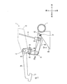
次に、上述した第1実施形態と異なる実施形態(第2実施形態)に係るブレーキペダル装置1の概略構成について、図5~図7を参照しつつ詳細に説明する。尚、第2実施形態に係るブレーキペダル装置1は、ペダルブラケット10、後退防止用リンク40の構成を除き、上述した第1実施形態に係るブレーキペダル装置1と同様の構成を有している。従って、以下の説明においては、第1実施形態と同様の構成についての説明を省略し、相違する構成について詳細に説明する。
次に、上述した第1実施形態と異なる実施形態(第2実施形態)に係るブレーキペダル装置1の概略構成について、図5~図7を参照しつつ詳細に説明する。尚、第2実施形態に係るブレーキペダル装置1は、ペダルブラケット10、後退防止用リンク40の構成を除き、上述した第1実施形態に係るブレーキペダル装置1と同様の構成を有している。従って、以下の説明においては、第1実施形態と同様の構成についての説明を省略し、相違する構成について詳細に説明する。
(第2実施形態に係るブレーキペダル装置の概略構成)
第2実施形態に係るブレーキペダル装置1においても、ペダルブラケット10は、ダッシュパネルPの車室側に対して、ボルト等を用いて固定されており、車幅方向に間隔をおいて対向する一対の側板を有している。当該ペダルブラケット10は、第1実施形態と同様の第1支持軸11に加えて、取付軸13を有している。
第2実施形態に係るブレーキペダル装置1においても、ペダルブラケット10は、ダッシュパネルPの車室側に対して、ボルト等を用いて固定されており、車幅方向に間隔をおいて対向する一対の側板を有している。当該ペダルブラケット10は、第1実施形態と同様の第1支持軸11に加えて、取付軸13を有している。
第2実施形態に係る第1支持軸11は、ペダルブラケット10における一対の側板の間に亘って、略水平で且つ車幅方向と略平行に延びており、操作ペダル20の上部を回動可能に支持している。この点、第2実施形態に係る第1支持軸11は、第1実施形態と異なり、後退防止用リンク40の端部の支持に用いられていない。
そして、第2実施形態においても、第2支持軸12は、操作ペダル20よりも車両後側において、第1支持軸11と平行に伸びるように配設されている。そして、当該第2支持軸12は、オペレーティングロッドRが接続された中間レバー25の下部を回動可能に支持すると共に、後退防止用リンク40の他端部を回動可能に支持している。更に、第2実施形態に係る第2支持軸12は、第1実施形態と同様に、後退防止用リンク40及び後退防止部材50を相互に回動可能に連結しており、本発明における連結位置として機能する。
第2実施形態に係るペダルブラケット10には、取付軸13が形成されている。当該取付軸13は、第1支持軸11よりも上方であって、且つ、スライドブラケット60に対する後退防止部材50の取付位置(即ち、固定ボルト51等の位置)よりも下方となる位置において、第1支持軸11と平行に伸びるように配設されている。そして、図5~図7に示すように、当該取付軸13は、後退防止用リンク40の一端部をペダルブラケット10に対して回動可能に取り付ける機能を果たしており、本発明における第1取付位置に相当する。
そして、第2実施形態に係る後退防止用リンク40は、第1実施形態と同様に、ペダルブラケット10の各側板に沿って配置された鋼板製の部材である。後退防止用リンク40における車両前方側の端部は、ペダルブラケット10の取付軸13によって回動可能に取り付けられており、車両後方側の端部は、第2支持軸12によって支持されている。ここで、取付軸13は、ペダルブラケット10に配設される一方で、第2支持軸12は、ペダルブラケット10を介さずに配設されている。従って、後退防止用リンク40は、第2支持軸12の移動に伴い、取付軸13まわりに回動し得る。
以上のように構成することで、第2実施形態に係るブレーキペダル装置1においては、図5に示すように、本発明における第2取付位置として機能する固定ボルト51及びナット52の位置は、本発明における第1取付位置として機能する取付軸13よりも上方に位置している。そして、第1取付位置と第2取付位置を結ぶ基準線Lは、車両後方側に向かうほど上方となるように傾斜している。そして、第2実施形態に係るブレーキペダル装置1では、本発明における連結位置として機能する第2支持軸12は、第1取付位置と第2取付位置を結ぶ基準線Lよりも下方に位置することになる。
(第2実施形態に係るブレーキペダル装置の前方衝突時における動作)
次に、第2実施形態に係るブレーキペダル装置1の車両の前方衝突時における動作について、図6、図7を参照しつつ詳細に説明する。第2実施形態においても、車両の前方衝突等によって車両前側から大荷重が入力された場合、ダッシュパネルPは、入力された大荷重によって車両後側へ変位する。そして、車両前側から入力された大荷重によるダッシュパネルPとインパネリインフォースメントIとの変位差によって、ブレーキペダル装置1は、ダッシュパネルPと共に、相対的に車両後側へ移動する。
次に、第2実施形態に係るブレーキペダル装置1の車両の前方衝突時における動作について、図6、図7を参照しつつ詳細に説明する。第2実施形態においても、車両の前方衝突等によって車両前側から大荷重が入力された場合、ダッシュパネルPは、入力された大荷重によって車両後側へ変位する。そして、車両前側から入力された大荷重によるダッシュパネルPとインパネリインフォースメントIとの変位差によって、ブレーキペダル装置1は、ダッシュパネルPと共に、相対的に車両後側へ移動する。
図5に示すように、第2実施形態に係るブレーキペダル装置1においては、連結位置として機能する第2支持軸12が基準線Lよりも下方に位置しており、後退防止用リンク40は、取付軸13と第2支持軸12の相対的な位置関係(距離)を保つように形成されている。これにより、ダッシュパネルPの後方変位による荷重は、後退防止用リンク40を取付軸13まわりに下方へ回動させるように作用する。この結果、ダッシュパネルPの後方変位による荷重は、連結位置である第2支持軸12を下方へ変位させる。
又、第2実施形態においても、第2取付位置として機能する固定ボルト51等の位置は、第1取付位置として機能する取付軸13の位置よりも上方に位置している。従って、当該ブレーキペダル装置1によれば、連結位置である第2支持軸12を、より確実に下方へ変位させることができる。
そして、第2実施形態においても、ダッシュパネルPの後方変位に伴い、第2支持軸12が下方に変位すると、中間レバー25も下方へ移動する。この中間レバー25の移動によって、操作ペダル20は、連結リンク30を介して引っ張られ、第1支持軸11まわりに強制的に回動する。即ち、図6に示すように、第2実施形態に係るブレーキペダル装置1においては、後退防止用リンク40及び後退防止部材50を連結する第2支持軸12を下方に変位させることで、操作ペダル20及び中間レバー25を強制的に回動させて、操作ペダル20の踏部21が運転席側へ後退することを抑制できる。
そして、第2実施形態においても、ダッシュパネルPの後方変位が更に進み、第2支持軸12が下方に変位していくと、所定の荷重(例えば、固定ボルト51及びナット52の締結荷重)を超えた段階で、後退防止部材50の固定ボルト51等が、スリット61の幅広部62に向かって移動していく(図7参照)。そして、固定ボルト51及びナット52がスリット61の幅広部62に到達した時点で、後退防止部材50は、スライドブラケット60から離脱する。これにより、第2実施形態に係るブレーキペダル装置1においても、ダッシュパネルPの後方変位による荷重が、車体側部材であるインパネリインフォースメントIを大きく変形させる前に取り除かれることになる。即ち、インパネリインフォースメントIの変形に伴うステアリングの車室内への変位を抑制することができるので、第2実施形態に係るブレーキペダル装置1も、車室内における乗員の上半身を確実に保護することができる。
以上説明したように、第2実施形態に係るブレーキペダル装置1は、第1実施形態と同様に、ペダルブラケット10と、操作ペダル20と、中間レバー25と、連結リンク30と、を有している。当該ブレーキペダル装置1は、踏込み操作に伴う操作ペダル20の回動に連動して、連結リンク30を介して中間レバー25を回動させることができ、結果として、ブレーキブースタBのオペレーティングロッドRを車両前側へ変位させ得る。
そして、第2実施形態に係るブレーキペダル装置1は、第1実施形態と同様に、後退防止用リンク40と、後退防止部材50を有している。そして、後退防止用リンク40と後退防止部材50を連結する第2支持軸12は、基準線Lよりも下方に位置している(図5参照)。これにより、当該ブレーキペダル装置1は、ダッシュパネルPが車両後側へ変位して、ダッシュパネルPとインパネリインフォースメントI等との間隔が狭まっていくと、後退防止用リンク40と後退防止部材50の連結位置である第2支持軸12を下方へ移動させ、第2支持軸12と共に中間レバー25を下方に移動させることができる(図6、図7参照)。この結果、当該ブレーキペダル装置1においては、中間レバー25の下方移動に伴い、操作ペダル20が、連結リンク30を介して引っ張られる。この為、当該ブレーキペダル装置1は、操作ペダル20を、第1支持軸11を中心として車両前方側へ回動させて、操作ペダル20の踏部21を車両後側へ変位することを抑制することができる。
又、第2実施形態に係るブレーキペダル装置1においても、ダッシュパネルPを車両後方側へ変位させる車両前方側からの荷重を、後退防止用リンク40と後退防止部材50の連結位置である第2支持軸12を下方へ移動させる方向に作用させることができ、インパネリインフォースメントI等の変形を抑制することができる。これにより、当該ブレーキペダル装置1は、インパネリインフォースメントIに配設されたステアリングの車室内への変位を抑制して、車室内における乗員の上半身を確実に保護することができる。
そして、第2実施形態に係るブレーキペダル装置1においても、後退防止部材50は、車両後方側へ所定量変位した場合に、車体側部材であるインパネリインフォースメントIに固設されたスライドブラケット60から離脱可能に取り付けられている。これにより、第2実施形態においても、ダッシュパネルPを車両後方側へ変位させる車両前方側からの荷重が車体側部材であるインパネリインフォースメントIの変形を引き起こす前に、その荷重を除外することができる。当該ブレーキペダル装置1は、結果として、ステアリングとの接触等を防止して、乗員の確実な保護に貢献し得る。
又、第2実施形態においても、前記第2取付位置である固定ボルト51等の位置は、前記第1取付位置として機能する取付軸13よりも上方に位置している。この為、車両の前方衝突等によって前記ダッシュパネルPが車両後側へ変位した場合に、後退防止用リンク40と後退防止部材50の連結位置である第2支持軸12を下方へ確実に移動させることができる。即ち、当該ブレーキペダル装置1によれば、操作ペダル20の踏部21が車両後側へ変位することを確実に抑制することができると同時に、インパネリインフォースメントIの変形を抑制することができ、結果として、乗員の上半身の確実な保護に貢献し得る。
そして、第2実施形態においても、第2支持軸12は、中間レバー25と後退防止用リンク40とを相互に回動可能に支持すると共に、後退防止用リンク40と後退防止部材50とを回動可能に連結している。従って、当該ブレーキペダル装置1は、部品点数を削減して製造コストを低減することができる。
(第3実施形態)
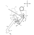
次に、上述した第1実施形態、第2実施形態と異なる実施形態(第3実施形態)に係るブレーキペダル装置1の概略構成について、図8~図10を参照しつつ詳細に説明する。尚、第3実施形態に係るブレーキペダル装置1は、ペダルブラケット10、後退防止用リンク40及び後退防止部材50の構成を除き、上述した第1実施形態、第2実施形態に係るブレーキペダル装置1と同様の構成を有している。従って、以下の説明においては、第1実施形態、第2実施形態と同様の構成についての説明を省略し、相違する構成について詳細に説明する。
次に、上述した第1実施形態、第2実施形態と異なる実施形態(第3実施形態)に係るブレーキペダル装置1の概略構成について、図8~図10を参照しつつ詳細に説明する。尚、第3実施形態に係るブレーキペダル装置1は、ペダルブラケット10、後退防止用リンク40及び後退防止部材50の構成を除き、上述した第1実施形態、第2実施形態に係るブレーキペダル装置1と同様の構成を有している。従って、以下の説明においては、第1実施形態、第2実施形態と同様の構成についての説明を省略し、相違する構成について詳細に説明する。
(第3実施形態に係るブレーキペダル装置の概略構成)
第3実施形態に係るブレーキペダル装置1においても、ペダルブラケット10は、ダッシュパネルPの車室側に対して、ボルト等を用いて固定されており、車幅方向に間隔をおいて対向する一対の側板を有している。当該ペダルブラケット10は、第2実施形態と同様に、第1支持軸11と、取付軸13を有している。
第3実施形態に係るブレーキペダル装置1においても、ペダルブラケット10は、ダッシュパネルPの車室側に対して、ボルト等を用いて固定されており、車幅方向に間隔をおいて対向する一対の側板を有している。当該ペダルブラケット10は、第2実施形態と同様に、第1支持軸11と、取付軸13を有している。
第3実施形態に係る第1支持軸11は、ペダルブラケット10における一対の側板の間に亘って、略水平で且つ車幅方向と略平行に延びており、操作ペダル20の上部を回動可能に支持している。第3実施形態に係る第1支持軸11は、第2実施形態と同様に、後退防止用リンク40の端部の支持に用いられていない。
そして、第3実施形態に係る第2支持軸12は、操作ペダル20よりも車両後側において、中間レバー25の下部を回動可能に支持すると共に、後退防止用リンク40の他端部を回動可能に支持している。更に、第3実施形態に係る第2支持軸12は、第1実施形態、第2実施形態と同様に、後退防止用リンク40及び後退防止部材50を相互に回動可能に連結しており、本発明における連結位置として機能する。
第3実施形態に係るペダルブラケット10には、取付軸13が形成されており、第1支持軸11よりも上方であって、且つ、スライドブラケット60に対する後退防止部材50の取付位置(即ち、固定ボルト51等の位置)と同じ高さとなる位置に位置している。そして、図8~図10に示すように、当該取付軸13は、後退防止用リンク40の一端部をペダルブラケット10に対して回動可能に取り付ける機能を果たしており、本発明における第1取付位置に相当する。
そして、第3実施形態に係る後退防止用リンク40は、第2実施形態と同様に、ペダルブラケット10の各側板に沿って配置された鋼板製の部材である。当該後退防止用リンク40の車両前方側の端部は、ペダルブラケット10の取付軸13によって回動可能に取り付けられており、車両後方側の端部は、第2支持軸12によって支持されている。ここで、取付軸13は、ペダルブラケット10に配設される一方で、第2支持軸12は、ペダルブラケット10を介さずに配設されている。この為、後退防止用リンク40は、第2支持軸12の移動に伴い、取付軸13まわりに回動し得る。そして、第3実施形態においては、後退防止用リンク40の両端に位置する取付軸13と第2支持軸12の間の距離を、第1距離DAという。
第3実施形態においては、後退防止部材50は、第1実施形態、第2実施形態と同様に、その一端部が車体側部材を構成するスライドブラケット60に対して取り付けられると共に、第2支持軸12を介して、後退防止用リンク40に対して回動可能に連結されている。当該後退防止部材50は、車両の前方衝突等により荷重が加わった場合には、車体側部材を構成するスライドブラケット60から離脱するように取り付けられている(図2参照)。そして、第3実施形態においては、後退防止部材50の一端側に位置する固定ボルト51等の位置(即ち、スライドブラケット60に対する後退防止部材50の取付位置)と第2支持軸12の間の距離を、第2距離DBといい、当該第2距離DBは、上述した第1距離DAよりも短く設定されている。
以上のように構成することで、第3実施形態に係るブレーキペダル装置1においては、図8に示すように、本発明における第2取付位置として機能する固定ボルト51及びナット52の位置は、本発明における第1取付位置として機能する取付軸13と同じ高さに位置している。第1取付位置と第2取付位置を結ぶ基準線Lは、車両の前後方向に関して水平に伸びている。そして、第3実施形態に係るブレーキペダル装置1では、本発明における連結位置として機能する第2支持軸12は、第1取付位置と第2取付位置を結ぶ基準線Lよりも下方に位置することになる。更に、第3実施形態においては、前記第1取付位置である取付軸13と前記連結位置である第2支持軸12との間を結ぶ第1距離DAは、前記第2取付位置である固定ボルト51等の位置と前記連結位置である第2支持軸12とを結ぶ第2距離DBよりも長い(図8参照)。
(第3実施形態に係るブレーキペダル装置の前方衝突時における動作)
次に、第3実施形態に係るブレーキペダル装置1の車両の前方衝突時における動作について、図9、図10を参照しつつ詳細に説明する。第3実施形態においても、車両の前方衝突等によって車両前側から大荷重が入力された場合、ダッシュパネルPは、入力された大荷重によって車両後側へ変位して、ブレーキペダル装置1をダッシュパネルPと共に、相対的に車両後側へ移動させる。
次に、第3実施形態に係るブレーキペダル装置1の車両の前方衝突時における動作について、図9、図10を参照しつつ詳細に説明する。第3実施形態においても、車両の前方衝突等によって車両前側から大荷重が入力された場合、ダッシュパネルPは、入力された大荷重によって車両後側へ変位して、ブレーキペダル装置1をダッシュパネルPと共に、相対的に車両後側へ移動させる。
図8に示すように、第3実施形態に係るブレーキペダル装置1においては、連結位置として機能する第2支持軸12が基準線Lよりも下方に位置しており、後退防止用リンク40は、取付軸13と第2支持軸12の相対的な位置関係(距離)を保つように形成されている。これにより、ダッシュパネルPの後方変位による荷重は、後退防止用リンク40を取付軸13まわりに下方へ回動させるように作用し、結果として、連結位置である第2支持軸12を下方へ変位させることができる。
ここで、第3実施形態においては、第2取付位置として機能する固定ボルト51等の位置は、第1取付位置として機能する取付軸13の位置と同じ高さに位置している。しかしながら、取付軸13と第2支持軸12を結ぶ第1距離DAが、固定ボルト51等と第2支持軸12を結ぶ第2距離DBよりも長く形成されている。このように形成することにより、当該ブレーキペダル装置1は、第1取付位置と第2取付位置の高さが同じ場合であっても、連結位置である第2支持軸12を、より確実に下方へ変位させることができる。
第3実施形態において、ダッシュパネルPの後方変位に伴い、第2支持軸12が下方に変位すると、中間レバー25も下方へ移動する。この中間レバー25の移動によって、操作ペダル20は、連結リンク30を介して引っ張られ、第1支持軸11まわりに強制的に回動する。即ち、図9に示すように、第3実施形態に係るブレーキペダル装置1においては、後退防止用リンク40及び後退防止部材50を連結する第2支持軸12を下方に変位させることで、操作ペダル20及び中間レバー25を強制的に回動させて、操作ペダル20の踏部21が運転席側へ後退することを抑制できる。
そして、第3実施形態においても、ダッシュパネルPの後方変位が更に進み、第2支持軸12が下方に変位していくと、所定の荷重(例えば、固定ボルト51及びナット52の締結荷重)を超えた段階で、後退防止部材50の固定ボルト51等が、スリット61の幅広部62に向かって移動していく(図10参照)。そして、固定ボルト51及びナット52がスリット61の幅広部62に到達した時点で、後退防止部材50は、スライドブラケット60から離脱する。これにより、第3実施形態に係るブレーキペダル装置1でも、ダッシュパネルPの後方変位による荷重が、車体側部材であるインパネリインフォースメントIを大きく変形させる前に取り除かれる。即ち、インパネリインフォースメントIの変形に伴うステアリングの車室内への変位を抑制することができるので、第3実施形態に係るブレーキペダル装置1も、車室内における乗員の上半身を確実に保護することができる。
以上説明したように、第3実施形態に係るブレーキペダル装置1は、第1実施形態と同様に、ペダルブラケット10と、操作ペダル20と、中間レバー25と、連結リンク30と、を有している。そして、当該ブレーキペダル装置1は、踏込み操作に伴う操作ペダル20の回動に連動して、連結リンク30を介して中間レバー25を回動させることができ、結果として、ブレーキブースタBのオペレーティングロッドRを車両前側へ変位させ得る。
そして、第3実施形態に係るブレーキペダル装置1は、第1実施形態、第2実施形態と同様に、後退防止用リンク40と、後退防止部材50を有しており、後退防止用リンク40と後退防止部材50を連結する第2支持軸12は、基準線Lよりも下方に位置している(図8参照)。これにより、当該ブレーキペダル装置1は、ダッシュパネルPが車両後側へ変位し、ダッシュパネルPとインパネリインフォースメントI等との間隔が狭まっていくと、後退防止用リンク40と後退防止部材50の連結位置である第2支持軸12を下方へ移動させ、第2支持軸12と共に中間レバー25を下方に移動させることができる(図9、図10参照)。この結果、当該ブレーキペダル装置1においては、中間レバー25の下方移動に伴い、操作ペダル20が連結リンク30を介して引っ張られる為、操作ペダル20を、第1支持軸11を中心として車両前方側へ回動させて、操作ペダル20の踏部21を車両後側へ変位することを抑制することができる。
又、第3実施形態に係るブレーキペダル装置1においても、ダッシュパネルPを車両後方側へ変位させる車両前方側からの荷重を、後退防止用リンク40と後退防止部材50の連結位置である第2支持軸12を下方へ移動させる方向に作用させることができる。この結果、当該ブレーキペダル装置1は、インパネリインフォースメントI等の変形を抑制することができる。これにより、当該ブレーキペダル装置1は、インパネリインフォースメントIに配設されたステアリングの車室内への変位を抑制して、車室内における乗員の上半身を確実に保護することができる。
そして、第3実施形態に係るブレーキペダル装置1においても、後退防止部材50は、車両後方側へ所定量変位した場合に、車体側部材であるスライドブラケット60から離脱可能に取り付けられている。これにより、第3実施形態においても、ダッシュパネルPを車両後方側へ変位させる車両前方側からの荷重が車体側部材であるインパネリインフォースメントIの変形を引き起こす前に、その荷重を除外することができる。当該ブレーキペダル装置1は、結果として、ステアリングとの接触等を防止して、乗員の確実な保護に貢献し得る。
第3実施形態において、前記第2取付位置である固定ボルト51等の位置は、前記第1取付位置として機能する取付軸13と同じ高さに位置している。しかしながら、取付軸13と連結位置である第2支持軸12との間を結ぶ第1距離DAは、固定ボルト51等の位置と第2支持軸12とを結ぶ第2距離DBよりも長い。この為、車両の前方衝突等によって前記ダッシュパネルPが車両後側へ変位した場合に、前記第2支持軸12を下方へ確実に移動させることができる。即ち、当該ブレーキペダル装置1によれば、操作ペダル20の踏部21が車両後側へ変位することを確実に抑制することができる。同時に、当該ブレーキペダル装置1は、インパネリインフォースメントIの変形を抑制することができ、乗員の上半身の確実な保護に貢献し得る。
そして、第3実施形態においても、第2支持軸12は、中間レバー25と後退防止用リンク40とを相互に回動可能に支持すると共に、後退防止用リンク40と後退防止部材50とを回動可能に連結している。従って、当該ブレーキペダル装置1は、部品点数を削減して製造コストを低減することができる。
以上、実施形態に基づき本発明を説明したが、本発明は上述した実施形態に何ら限定されるものではなく、本発明の趣旨を逸脱しない範囲内で種々の改良変更が可能である。例えば、上述した各実施形態においては、中間レバー25の回動軸である第2支持軸12を用いて、後退防止用リンク40と後退防止部材50を相互に回動可能を連結していたが、この態様に限定されるものではなく、後退防止用リンク40と後退防止部材50を相互に回動可能を連結する構成を、第2支持軸12とは別に設けてもよい。
例えば、図11に示すように、側面視略L字状に形成された後退防止用リンク40の角部分を、第2支持軸12によって回動可能に支持すると共に、その前方側の端部を、ペダルブラケット10の取付軸13に対して回動可能に取り付ける。そして、略L字状を為す後退防止用リンク40の後方側端部と、後退防止部材50とを、連結軸14によって相互に回動可能に連結する。即ち、この図11に示す場合、連結軸14が本発明に係る連結位置として機能し、基準線Lよりも下方に位置している。
従って、この場合においても、ダッシュパネルPが車両後側へ変位し、ダッシュパネルPとインパネリインフォースメントI等との間隔が狭まっていくと、当該ブレーキペダル装置1は、連結位置である連結軸14を下方に移動させる。連結軸14が下方に移動することで後退防止用リンク40も下方に移動する為、第2支持軸12と共に中間レバー25も下方に移動する。これにより、連結リンク30を介して、操作ペダル20が下方に引っ張られることになる為、当該ブレーキペダル装置1は、操作ペダル20を、第1支持軸11を中心として車両前方側へ回動させて、操作ペダル20の踏部21を車両後側へ変位することを抑制することができる。
又、この場合においても、ダッシュパネルPを車両後方側へ変位させる車両前方側からの荷重を、連結位置である連結軸14を下方へ移動させる方向に作用させることができる。この為、当該ブレーキペダル装置1は、インパネリインフォースメントI等の変形を抑制することができる。これにより、当該ブレーキペダル装置1は、インパネリインフォースメントIに配設されたステアリングの車室内への変位を抑制して、車室内における乗員の上半身を確実に保護することができる。
そして、上述した実施形態においては、スライドブラケット60に対する後退防止部材50の離脱構造を、スライドブラケット60に形成され、幅広部62を有するスリット61と、後退防止部材50に取り付けられた固定ボルト51及びナット52によって実現していたが、後退防止部材50が車両後方側へ所定量変位した場合に、スライドブラケット60から離脱可能な構成であれば種々の態様を採用することができる。例えば、所定以上の離脱荷重が作用した場合に破断するリベットを用いて、スライドブラケット60に対して、後退防止部材50を取り付けてもよい。又、後退防止部材50に形成された取付軸を、スライドブラケット60に形成された保持穴で保持するように構成し、当該保持穴における車両後方側に、取付軸の外径よりも小さな開口幅を有する開口部を形成してもよい。この場合、後退防止部材50が車両後方側に所定量変位した場合に、取付軸を、開口部を介して保持穴外部へ移動させることができ、もって、スライドブラケット60から後退防止部材50を離脱させることができる。
又、本発明に係る車両用ペダル装置の後退防止装置における各動作を実現することができれば、上述した実施形態に示す態様に限定されるものではなく、ブレーキペダル装置1を構成する各部材の配置を適宜変更することができる。
更に、本発明に係る車両用ペダル装置の後退防止装置における各動作を実現することができれば、各構成部材の形状を適宜変更し得る。各構成部材の形状は、上述した実施形態におけるブレーキペダル装置1の各構成部材の形状に限定されるものではなく、例えば、各構成部材間の干渉を避ける為に、構成部材夫々の形状を変更してもよい。
1 ブレーキペダル装置
10 ペダルブラケット
11 第1支持軸
12 第2支持軸
13 取付軸
14 連結軸
20 操作ペダル
21 踏部
25 中間レバー
30 連結リンク
40 後退防止用リンク
50 後退防止部材
51 固定ボルト
52 ナット
60 スライドブラケット
I インパネリインフォースメント
L 基準線
DA 第1距離
DB 第2距離
10 ペダルブラケット
11 第1支持軸
12 第2支持軸
13 取付軸
14 連結軸
20 操作ペダル
21 踏部
25 中間レバー
30 連結リンク
40 後退防止用リンク
50 後退防止部材
51 固定ボルト
52 ナット
60 スライドブラケット
I インパネリインフォースメント
L 基準線
DA 第1距離
DB 第2距離
Claims (6)
- 車両前側のダッシュパネルに固定されたペダルブラケットと、
前記ペダルブラケットの第1支持軸によって回動可能に配設され、車両前側への踏込み操作に用いられる踏部を有する操作ペダルと、
前記第1支持軸よりも車両後方側において、当該第1支持軸に平行に設けられた第2支持軸まわりに回動可能に支持されると共に、前記第2支持軸を軸とした出力方向への回動によって、所定の出力部材を車両前側へ変位させる中間レバーと、
前記操作ペダルと前記中間レバーを連結し、前記操作ペダルに対する踏込み操作に連動して、前記中間レバーを前記出力方向へ回動させる連結リンクと、を有する車両用ペダル装置に関し、前記ダッシュパネルが車両後側へ変位した場合に、前記操作ペダルの踏部の車両後側への変位を抑制する後退防止装置であって、
前記ペダルブラケットに対して一端部が回動可能に取り付けられると共に、前記第2支持軸を中心として回動可能に支持された第1後退防止部材と、
車両後方側に位置する車体側部材に対して一端部が取り付けられると共に、前記第1後退防止部材に対して回動可能に連結された第2後退防止部材と、を有し、
前記第1後退防止部材と前記第2後退防止部材を回動可能に連結した連結位置は、前記ペダルブラケットに対して前記第1後退防止部材が取り付けられている第1取付位置と、前記車体側部材に対して前記第2後退防止部材が取り付けられている第2取付位置とを結ぶ基準線よりも下方に位置している
ことを特徴とする車両用ペダル装置の後退防止装置。 - 前記第2後退防止部材は、車両後方側へ所定量変位した場合に、一端部が前記車体側部材から離脱可能に取り付けられている
ことを特徴とする請求項1記載の車両用ペダル装置の後退防止装置。 - 前記第2取付位置は、前記第1取付位置よりも上方に位置している
ことを特徴とする請求項1又は請求項2記載の車両用ペダル装置の後退防止装置。 - 前記第1取付位置と前記連結位置との間を結ぶ第1距離は、前記第2取付位置と前記連結位置とを結ぶ第2距離よりも長い
ことを特徴とする請求項1乃至請求項3の何れかに記載の車両用ペダル装置の後退防止装置。 - 前記第1支持軸は、
前記ペダルブラケットに対して前記操作ペダルを回動可能に支持すると共に、前記ペダルブラケットに対して前記第1後退防止部材を回動可能に支持する
ことを特徴とする請求項1乃至請求項4の何れかに記載の車両用ペダル装置の後退防止装置。 - 前記第2支持軸は、
前記中間レバーと前記第1後退防止部材とを相互に回動可能に支持すると共に、前記第1後退防止部材と前記第2後退防止部材とを回動可能に連結する
ことを特徴とする請求項1乃至請求項5の何れかに記載の車両用ペダル装置の後退防止装置。
Applications Claiming Priority (2)
| Application Number | Priority Date | Filing Date | Title |
|---|---|---|---|
| JP2015-135098 | 2015-07-06 | ||
| JP2015135098A JP2017016551A (ja) | 2015-07-06 | 2015-07-06 | 車両用ペダル装置の後退防止装置 |
Publications (1)
| Publication Number | Publication Date |
|---|---|
| WO2017006627A1 true WO2017006627A1 (ja) | 2017-01-12 |
Family
ID=57685379
Family Applications (1)
| Application Number | Title | Priority Date | Filing Date |
|---|---|---|---|
| PCT/JP2016/064687 Ceased WO2017006627A1 (ja) | 2015-07-06 | 2016-05-18 | 車両用ペダル装置の後退防止装置 |
Country Status (2)
| Country | Link |
|---|---|
| JP (1) | JP2017016551A (ja) |
| WO (1) | WO2017006627A1 (ja) |
Citations (4)
| Publication number | Priority date | Publication date | Assignee | Title |
|---|---|---|---|---|
| JP2001047986A (ja) * | 1999-08-03 | 2001-02-20 | Daihatsu Motor Co Ltd | フットペダルの退避構造 |
| JP2003276582A (ja) * | 2002-03-20 | 2003-10-02 | Kuroishi Tekko Kk | 車両用ブレーキペダルユニット |
| JP2008204096A (ja) * | 2007-02-19 | 2008-09-04 | Toyota Motor Corp | 車両用ペダル支持構造 |
| JP2014119927A (ja) * | 2012-12-14 | 2014-06-30 | Toyoda Iron Works Co Ltd | 車両用ペダル装置 |
-
2015
- 2015-07-06 JP JP2015135098A patent/JP2017016551A/ja active Pending
-
2016
- 2016-05-18 WO PCT/JP2016/064687 patent/WO2017006627A1/ja not_active Ceased
Patent Citations (4)
| Publication number | Priority date | Publication date | Assignee | Title |
|---|---|---|---|---|
| JP2001047986A (ja) * | 1999-08-03 | 2001-02-20 | Daihatsu Motor Co Ltd | フットペダルの退避構造 |
| JP2003276582A (ja) * | 2002-03-20 | 2003-10-02 | Kuroishi Tekko Kk | 車両用ブレーキペダルユニット |
| JP2008204096A (ja) * | 2007-02-19 | 2008-09-04 | Toyota Motor Corp | 車両用ペダル支持構造 |
| JP2014119927A (ja) * | 2012-12-14 | 2014-06-30 | Toyoda Iron Works Co Ltd | 車両用ペダル装置 |
Also Published As
| Publication number | Publication date |
|---|---|
| JP2017016551A (ja) | 2017-01-19 |
Similar Documents
| Publication | Publication Date | Title |
|---|---|---|
| EP1375277B1 (en) | Vehicular pedal supporting structure | |
| WO2015145640A1 (ja) | 自動車のブレーキペダル装置 | |
| JP2002053017A (ja) | 自動車のペダル支持構造 | |
| JP6572112B2 (ja) | 車両用操作ペダルの支持構造 | |
| WO2017006627A1 (ja) | 車両用ペダル装置の後退防止装置 | |
| WO2018150976A1 (ja) | 車両の内装構造 | |
| JP6280083B2 (ja) | 車両用ペダル装置の後退防止装置 | |
| JP7533791B2 (ja) | 電動車両 | |
| JP6350419B2 (ja) | 自動車のペダル後退防止構造 | |
| JP2004114793A (ja) | 自動車のペダル支持構造 | |
| JP6189347B2 (ja) | 車両用ペダル装置の後退防止装置 | |
| JP6352229B2 (ja) | 車両用ペダル装置の後退防止装置 | |
| JP2011248720A (ja) | 車両のペダル装置 | |
| JP2005206104A (ja) | 車両のステアリング支持構造 | |
| JP2011037377A (ja) | 自動車のブレーキペダル装置 | |
| WO2010131343A1 (ja) | 車両ボディ構造体 | |
| JP4623425B2 (ja) | 車両用ペダル変位抑制構造 | |
| JP2005225460A (ja) | 車両用アンダプロテクタ構造 | |
| JP4389592B2 (ja) | 車両のステアリング支持構造 | |
| JP2016192199A (ja) | 車両用ペダル装置の後退防止装置 | |
| JP4389591B2 (ja) | 車両のステアリング支持構造 | |
| JP2010218184A (ja) | 車両の操作ペダル支持構造 | |
| JP2012008698A (ja) | ブレーキペダル後退防止装置 | |
| JP2022182501A (ja) | 車両のペダル後退防止構造 | |
| JPH07132836A (ja) | ステアリング装置 |
Legal Events
| Date | Code | Title | Description |
|---|---|---|---|
| 121 | Ep: the epo has been informed by wipo that ep was designated in this application |
Ref document number: 16821098 Country of ref document: EP Kind code of ref document: A1 |
|
| NENP | Non-entry into the national phase |
Ref country code: DE |
|
| 122 | Ep: pct application non-entry in european phase |
Ref document number: 16821098 Country of ref document: EP Kind code of ref document: A1 |