WO2017006623A1 - パワーステアリング装置及びパワーステアリング装置の制御装置 - Google Patents
パワーステアリング装置及びパワーステアリング装置の制御装置 Download PDFInfo
- Publication number
- WO2017006623A1 WO2017006623A1 PCT/JP2016/064478 JP2016064478W WO2017006623A1 WO 2017006623 A1 WO2017006623 A1 WO 2017006623A1 JP 2016064478 W JP2016064478 W JP 2016064478W WO 2017006623 A1 WO2017006623 A1 WO 2017006623A1
- Authority
- WO
- WIPO (PCT)
- Prior art keywords
- power steering
- steering
- determination unit
- abnormality determination
- abnormality
- Prior art date
- Legal status (The legal status is an assumption and is not a legal conclusion. Google has not performed a legal analysis and makes no representation as to the accuracy of the status listed.)
- Ceased
Links
Images






Classifications
-
- B—PERFORMING OPERATIONS; TRANSPORTING
- B62—LAND VEHICLES FOR TRAVELLING OTHERWISE THAN ON RAILS
- B62D—MOTOR VEHICLES; TRAILERS
- B62D5/00—Power-assisted or power-driven steering
- B62D5/04—Power-assisted or power-driven steering electrical, e.g. using an electric servo-motor connected to, or forming part of, the steering gear
- B62D5/0457—Power-assisted or power-driven steering electrical, e.g. using an electric servo-motor connected to, or forming part of, the steering gear characterised by control features of the drive means as such
- B62D5/0481—Power-assisted or power-driven steering electrical, e.g. using an electric servo-motor connected to, or forming part of, the steering gear characterised by control features of the drive means as such monitoring the steering system, e.g. failures
- B62D5/0487—Power-assisted or power-driven steering electrical, e.g. using an electric servo-motor connected to, or forming part of, the steering gear characterised by control features of the drive means as such monitoring the steering system, e.g. failures detecting motor faults
-
- B—PERFORMING OPERATIONS; TRANSPORTING
- B62—LAND VEHICLES FOR TRAVELLING OTHERWISE THAN ON RAILS
- B62D—MOTOR VEHICLES; TRAILERS
- B62D5/00—Power-assisted or power-driven steering
- B62D5/04—Power-assisted or power-driven steering electrical, e.g. using an electric servo-motor connected to, or forming part of, the steering gear
- B62D5/0457—Power-assisted or power-driven steering electrical, e.g. using an electric servo-motor connected to, or forming part of, the steering gear characterised by control features of the drive means as such
- B62D5/0481—Power-assisted or power-driven steering electrical, e.g. using an electric servo-motor connected to, or forming part of, the steering gear characterised by control features of the drive means as such monitoring the steering system, e.g. failures
- B62D5/0484—Power-assisted or power-driven steering electrical, e.g. using an electric servo-motor connected to, or forming part of, the steering gear characterised by control features of the drive means as such monitoring the steering system, e.g. failures for reaction to failures, e.g. limp home
-
- B—PERFORMING OPERATIONS; TRANSPORTING
- B62—LAND VEHICLES FOR TRAVELLING OTHERWISE THAN ON RAILS
- B62D—MOTOR VEHICLES; TRAILERS
- B62D5/00—Power-assisted or power-driven steering
- B62D5/04—Power-assisted or power-driven steering electrical, e.g. using an electric servo-motor connected to, or forming part of, the steering gear
- B62D5/0457—Power-assisted or power-driven steering electrical, e.g. using an electric servo-motor connected to, or forming part of, the steering gear characterised by control features of the drive means as such
- B62D5/046—Controlling the motor
- B62D5/0463—Controlling the motor calculating assisting torque from the motor based on driver input
-
- B—PERFORMING OPERATIONS; TRANSPORTING
- B62—LAND VEHICLES FOR TRAVELLING OTHERWISE THAN ON RAILS
- B62D—MOTOR VEHICLES; TRAILERS
- B62D5/00—Power-assisted or power-driven steering
- B62D5/04—Power-assisted or power-driven steering electrical, e.g. using an electric servo-motor connected to, or forming part of, the steering gear
- B62D5/0457—Power-assisted or power-driven steering electrical, e.g. using an electric servo-motor connected to, or forming part of, the steering gear characterised by control features of the drive means as such
- B62D5/0481—Power-assisted or power-driven steering electrical, e.g. using an electric servo-motor connected to, or forming part of, the steering gear characterised by control features of the drive means as such monitoring the steering system, e.g. failures
-
- B—PERFORMING OPERATIONS; TRANSPORTING
- B62—LAND VEHICLES FOR TRAVELLING OTHERWISE THAN ON RAILS
- B62D—MOTOR VEHICLES; TRAILERS
- B62D6/00—Arrangements for automatically controlling steering depending on driving conditions sensed and responded to, e.g. control circuits
-
- B—PERFORMING OPERATIONS; TRANSPORTING
- B62—LAND VEHICLES FOR TRAVELLING OTHERWISE THAN ON RAILS
- B62D—MOTOR VEHICLES; TRAILERS
- B62D6/00—Arrangements for automatically controlling steering depending on driving conditions sensed and responded to, e.g. control circuits
- B62D6/08—Arrangements for automatically controlling steering depending on driving conditions sensed and responded to, e.g. control circuits responsive only to driver input torque
-
- B—PERFORMING OPERATIONS; TRANSPORTING
- B60—VEHICLES IN GENERAL
- B60Y—INDEXING SCHEME RELATING TO ASPECTS CROSS-CUTTING VEHICLE TECHNOLOGY
- B60Y2400/00—Special features of vehicle units
- B60Y2400/30—Sensors
- B60Y2400/307—Torque sensors
-
- G—PHYSICS
- G01—MEASURING; TESTING
- G01L—MEASURING FORCE, STRESS, TORQUE, WORK, MECHANICAL POWER, MECHANICAL EFFICIENCY, OR FLUID PRESSURE
- G01L5/00—Apparatus for, or methods of, measuring force, work, mechanical power, or torque, specially adapted for specific purposes
- G01L5/22—Apparatus for, or methods of, measuring force, work, mechanical power, or torque, specially adapted for specific purposes for measuring the force applied to control members, e.g. control members of vehicles, triggers
- G01L5/221—Apparatus for, or methods of, measuring force, work, mechanical power, or torque, specially adapted for specific purposes for measuring the force applied to control members, e.g. control members of vehicles, triggers to steering wheels, e.g. for power assisted steering
-
- G—PHYSICS
- G01—MEASURING; TESTING
- G01N—INVESTIGATING OR ANALYSING MATERIALS BY DETERMINING THEIR CHEMICAL OR PHYSICAL PROPERTIES
- G01N27/00—Investigating or analysing materials by the use of electric, electrochemical, or magnetic means
- G01N27/02—Investigating or analysing materials by the use of electric, electrochemical, or magnetic means by investigating impedance
- G01N27/04—Investigating or analysing materials by the use of electric, electrochemical, or magnetic means by investigating impedance by investigating resistance
- G01N27/12—Investigating or analysing materials by the use of electric, electrochemical, or magnetic means by investigating impedance by investigating resistance of a solid body in dependence upon absorption of a fluid; of a solid body in dependence upon reaction with a fluid, for detecting components in the fluid
- G01N27/121—Investigating or analysing materials by the use of electric, electrochemical, or magnetic means by investigating impedance by investigating resistance of a solid body in dependence upon absorption of a fluid; of a solid body in dependence upon reaction with a fluid, for detecting components in the fluid for determining moisture content, e.g. humidity, of the fluid
Definitions
- the present invention relates to a power steering device applied to a vehicle and a control device for the power steering device.
- Patent Document 1 As a conventional power steering device, one described in Patent Document 1 below is known.
- This power steering device is provided with a power transmission mechanism that converts the rotational force of the electric motor into a moving force in the axial direction of the rack bar and transmits it to the rack bar. Further, in the power steering device, the outer periphery of the rack bar and the power transmission mechanism is liquid-tightly covered by the housing, and when water enters the housing, the power steering device is disposed inside the housing. The power steering device is determined to be abnormal by detecting with the water detection sensor.
- the present invention has been devised in view of such technical problems, and it is an object of the present invention to provide a power steering device and a control device for the power steering device that can determine an abnormality of the power steering device from various viewpoints. .
- the present invention is provided with a steering mechanism that transmits rotation of a steering wheel to a steered wheel, an electric motor that applies a steering force to the steering mechanism, and the steering mechanism and the electric motor.
- a transmission mechanism that transmits rotational force to the steering mechanism, a housing that houses at least a part of the steering mechanism, the transmission mechanism, and the electric motor, and a housing that is provided in the housing and detects moisture in the housing
- a first abnormality determination that determines an abnormality of the power steering device based on a moisture detection element, a torque sensor that detects a steering torque generated in the steering mechanism, and a signal of the steering torque, the rotation speed of the electric motor, or a steering speed
- a second abnormality determination unit that determines that the power steering device is abnormal when the moisture detection element detects moisture. It is characterized in Rukoto.
- the present invention it is possible to determine the abnormality of the power steering apparatus from a multifaceted viewpoint.
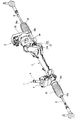
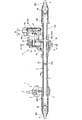
- FIG. 1 is a perspective view showing a power steering device according to a first embodiment of the present invention. It is a longitudinal cross-sectional view of the same power steering apparatus. It is a fragmentary sectional view of the torque sensor concerning this embodiment. It is a perspective view which shows the internal structure of the rudder angle sensor which concerns on this embodiment.
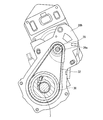
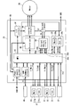
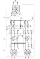
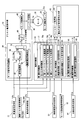
- FIG. 3 is a sectional view taken along line AA in FIG. 2. It is a block diagram which shows the structure of the electric system which concerns on ECU of this embodiment. It is a sensor block diagram which shows the connection relationship between ECU, a torque sensor, a steering angle sensor, and a rotation angle sensor. It is a control block diagram which shows the arithmetic circuit structure of ECU which concerns on this embodiment.
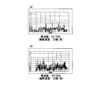
- (A) is a graph showing data when a power steering device having a new ball screw mechanism is installed on a table and performing an experiment
- (b) is a graph showing the power steering device having a rusted ball screw mechanism. It is a graph which shows the data when installing and experimenting.
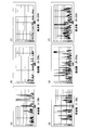
- (A) to (c) are graphs showing data when experimented on a paved road surface
- (d) to (f) are graphs showing data when experimented on a road surface having gravel. is there.
- the power steering device includes a steering mechanism 1 for transmitting rotation of a steering wheel (not shown) to a steered wheel (not shown), and a steering assist force applied to the steering mechanism 1 based on steering information and the like.
- a steering assist mechanism 2 that assists the steering operation of the driver, and a part of each of these mechanisms 1 and 2 is housed inside the housing 3.
- the steering mechanism 1 has an input shaft 4 whose one end is linked to the steering wheel so as to rotate integrally therewith, and one end connected to the input shaft 4 via a torsion bar 5 (see FIG. 3).
- the output shaft 6 connected so as to be relatively rotatable and the rack teeth (not shown) formed on the outer periphery mesh with the pinion teeth 6a (see FIGS. 3 and 4) on the outer periphery of the other end of the output shaft 6 in the axial direction.
- the rack bar 7 is moved mainly to the rack bar 7.
- the both ends of the rack bar 7 are linked to the steered wheels via tie rods 8 and 8 and a knuckle arm (not shown), respectively.
- each knuckle arm As the wheel is pulled, the direction of each steered wheel is changed.
- a sensor housing 9 that houses the input shaft 4 and the output shaft 6 includes a torque sensor 10 that detects a steering torque generated in the steering mechanism 1 by a steering operation of a driver, and a neutral position of the steering wheel. And a steering angle sensor 11 that detects a steering angle that is the amount of rotation from the steering wheel.
- the torque sensor 10 is provided so as to be integrally rotatable with the output shaft 6, and an annular permanent magnet 12 in which different magnetic poles are alternately arranged in the circumferential direction, and the permanent magnet at the lower part.
- a pair of inner and outer annular yoke members 13, 14 each having a plurality of claw portions 13 a, 14 a facing the outer peripheral surface of the twelve outer peripheral surface, and provided between the yoke members 13, 14.
- a pair of first and second magnetic flux collecting rings 15, 16 that generate a magnetic field inside based on the magnetic field of the permanent magnet 12 that flows between adjacent magnetic poles across 14 a, and between these magnetic flux collecting rings 15, 16.
- a magnetic sensor 17 comprising a main and sub pair of Hall elements 17a and 17b (see FIGS. 6 and 7) for detecting a change in the internal magnetic field between the magnetism collecting rings 15 and 16. .
- the permanent magnet 12 is adjacent to the claw portions 13a and 14a as the relative angular difference from the yoke members 13 and 14 increases, that is, as the torsion angle of the torsion bar 5 increases.
- the magnetic flux density of the magnetic field flowing between the magnetic poles is set to be large. As the magnetic flux density increases, the magnetic flux density of the internal magnetic field between the magnetic flux collecting rings 15 and 16 also increases.
- the torque sensor 10 can detect the steering torque by detecting a change in the magnetic flux density of the internal magnetic field between the magnetism collecting rings 15 and 16 by using the Hall effect of the Hall element of the magnetic sensor 17. It has become.
- the rudder angle sensor 11 is provided in a casing 18 constituting a part of the sensor housing 9, and a large gear 19 provided on the outer periphery of the input shaft 4 so as to be integrally rotatable.
- a first small gear 20 that meshes with and rotates with the large gear 19 and a second small gear that rotates with meshing with the first small gear 20 and having a different number of teeth from the first gear. 21.
- a pair of main and sub first MR elements 22a and 23a for detecting the rotation angle (first rotation angle) of the first small gear 20 are attached.
- a pair of main and sub MR elements 22b and 23b for detecting the rotation angle (second rotation angle) of the second small gear 21 are attached.
- the main MR elements 22a and 22b constitute a main rudder angle detecting element 22 (see FIG. 6)
- the sub MR elements 23a and 23b constitute a sub rudder angle detecting element 23 (FIG. 6). Reference) is configured.
- Each of the steering angle detection elements 22 and 23 rotates from the neutral position of the steering wheel based on the angular difference between the first and second rotation angles detected by the corresponding MR elements 22a, 22b, 23a and 23b.
- the steering angle which is a quantity, is detected.
- the steering assist mechanism 2 includes a motor unit 24 that outputs a steering assist force based on detection results of the torque sensor 10 and the steering angle sensor 11, and a steering assist force output by the motor unit 24.
- a transmission mechanism (decelerator) 25 that converts (rotational force) into an axial movement force of the rack bar 7 and transmits it to the rack bar 7 while decelerating.
- the motor unit 24 is attached to the electric motor 26 and an electric motor 26 that applies a steering assist force to the rack bar 7 via the transmission mechanism 25 by rotationally driving an input pulley 29 described later.
- An ECU 27 that is a control device that drives and controls the electric motor 26 according to parameters such as torque and vehicle speed is integrally configured.
- the electric motor 26 is a so-called brushless DC motor, and is not shown by a motor rotation angle sensor 28 (see FIGS. 6 and 7) having a pair of main and sub angle detection elements 28a and 28b provided in the ECU 27. The rotation angle of the rotor is detected.
- the transmission mechanism 25 is provided on the outer peripheral side of the output shaft 26a of the electric motor 26 so as to be integrally rotatable, and an input pulley 29 that rotates around the axis of the output shaft 26a.
- An output pulley 30 provided on the outer peripheral side of the rack bar 7 so as to be relatively rotatable, and rotating about the axis of the rack bar 7 based on the rotational force of the input pulley 29; the output pulley 30 and the rack bar 7; A ball screw mechanism 31 that converts the output pulley 30 into an axial motion of the rack bar 7 while decelerating the rotation of the output pulley 30, and is wound between the pulleys 29 and 30; A belt 32 is provided mainly for transmitting the rotation of the input pulley 29 to the output pulley 30 to provide synchronous rotation of the pulleys 29 and 30.
- the housing 3 includes first and second gear housing components 33 a and 33 b that are divided into two in the left-right direction of the vehicle, and a rack that is a part of the steering mechanism 1 inside.
- a gear housing 33 that accommodates the bar 7 and the transmission mechanism 25, a motor housing 34 that accommodates the electric motor 26 therein, and an ECU housing 35 that accommodates the ECU 27 therein.
- Each of the housings 33 to 35 is formed with an opening at a connecting portion with an adjacent housing, and the internal spaces are in communication with each other through the openings.
- the gear housing 33 has openings at both ends in the axial direction of the rack bar 7, and bellows-like boots 36, 36 are provided at the openings.
- Each boot 36, 36 has one end 36 a attached to the outer peripheral surface of the tie rods 8, 8, while the other end 36 b is attached to the outer peripheral surface of the gear housing 33, to the inside of the housing 3. The intrusion of water or dust is restricted.
- a water detection sensor 37 which is a moisture detection element that detects when moisture enters the housing 3, is provided.
- the water detection sensor 37 includes a pair of electrodes 38 and 39 disposed substantially in parallel with the output shaft 24a at a lower position inside the electric motor 26. Both electrodes 38 and 39 are provided in a slightly spaced state, and one end portions 38a and 39a on the input pulley 29 side protrude into the motor housing 34, and the other end side is electrically connected to the ECU 27. It is connected.
- the ECU 27 applies a voltage to one electrode 38 of both electrodes 38 and 39 constantly or at a constant cycle and monitors the other electrode 39, and the voltage is applied to the other electrode 39. Therefore, it is determined that water has entered the housing 3.
- the moisture is picked up by the rotation of the belt 32 and is supplied to the water detection sensor 37 in the motor housing 34. By arriving, it is electrically connected through moisture, and a voltage is applied from the one electrode 38 to the other electrode 39. By detecting this voltage by the ECU 27, it is determined whether water has entered the housing 3.
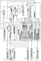
- FIG. 6 is a block diagram showing a configuration of an electrical system related to the ECU 27.
- the ECU 27 includes a power supply circuit 41 having a role of a power supply in the ECU 27, and an MPU (microprocessor) 42 that is activated by being supplied with power from the power supply circuit 41 and performs various arithmetic processes.
- a pre-driver 43 that is an integrated circuit (IC) to which a command signal is input from the MPU 42, and an inverter circuit 44 that is driven and controlled based on the command signal from the pre-driver 43.
- IC integrated circuit
- the power supply circuit 41 When power is supplied from the battery VB as the vehicle ignition switch is turned on, the power supply circuit 41 appropriately reduces the power while the MPU 42, the torque sensor 10, the steering angle sensor 11, and the motor rotation angle sensor 28. The water detection sensor 37 and the pre-driver 43 are supplied.
- the MPU 42 is electrically connected to the water detection sensor 37 and a vehicle speed sensor 45 installed in a differential gear (not shown).
- the water detection signal Sig from the water detection sensor 37 and the vehicle speed sensor 45 are connected to the MPU 42.
- the vehicle speed signal Vs from is input.
- the water detection signal Sig is switched on and off in accordance with the presence or absence of water detection by the water detection sensor 37. When water is not detected, “0” is input to the MPU 42 while water is not detected. When “1” is detected, “1” is input to the MPU 42.
- the MPU 42 is also electrically connected to the torque sensor 10, the steering angle sensor 11, and the motor rotation angle sensor 28, and main and sub steering torque signals Tr (Main), Tr (Sub) from the torque sensor 10. ), Main and sub steering angle signals ⁇ s (Main) and ⁇ s (Sub) from the steering angle sensor 11, and main and sub motor rotation angle signals ⁇ m (Main) and ⁇ m (Sub) from the motor rotation angle sensor 28. ) Is entered.
- the MPU 42 receives these main and sub various signals, one of these signals is used as a steering torque signal Tr, a steering angle signal ⁇ s, and a motor rotation angle signal ⁇ m for various calculation processes. (See FIG. 8).
- the inverter circuit 44 When the inverter circuit 44 receives a command signal from the pre-driver 43, the inverter circuit 44 converts the power from the battery VB from direct current to alternating current in accordance with the command signal, and supplies the power to the electric motor 26. Note that a fail-safe between the battery VB and the inverter circuit 44 is used to cut off the power sent from the battery VB to the inverter circuit 44 based on a command from the MPU 42 when a failure or the like occurs in the power steering device. A circuit 56 is interposed.
- a motor current detector 57 for detecting a motor actual current Im that is an actual current flowing through the electric motor 26 is provided on the downstream side of the inverter circuit 44.
- the motor actual current Im detected by the motor current detection unit 57 is input to a current monitoring circuit 58 provided in the ECU 27, and is then subjected to a high response filter by a pair of main and sub current detection circuits 59a and 59b for motor control. While being processed, it is fed back to the MPU 42 and also fed back to the MPU 42 in a state where low response filter processing is performed by a pair of main and sub current detection circuits 59c and 59d for overcurrent detection.
- FIG. 7 is a sensor block diagram showing a specific connection relationship between the MPU 42 and the torque sensor 10, the steering angle sensor 11, and the rotation angle sensor 28.
- the main and sub hall elements 17a and 17b of the torque sensor 10 are connected to the MPU 42 via steering torque signal receivers 49a and 49b provided in the ECU 27, and the hall elements 17a. , 17b detected by the main and sub steering torque signals Tr (Main), Tr (Sub).
- the MPU 42 is connected to the main first and second MR elements 22a and 22b of the steering angle sensor 11 via a first steering angle signal receiving unit 50a provided in the ECU 27, and both MR elements are connected to each other.
- the steering angle signal ⁇ s (Main) calculated based on the detected difference between the first and second rotation angles is input, and the second steering angle signal receiving unit 50b provided in the ECU 27 is used to input the steering angle signal ⁇ s (Main).
- the sub first and second MR elements 23a and 23b of the steering angle sensor 11 are connected, and a steering angle signal ⁇ s (Sub) calculated based on the angular difference between the MR elements 23a and 23b is input.
- main and sub angle detection elements 28a and 28b of the rotation angle sensor 28 are connected to the MPU 42, and main and sub motor rotation angle signals ⁇ m (Main) and ⁇ m (from the angle detection elements 28a and 28b). Sub) is input.
- FIG. 8 is a control block diagram showing the arithmetic circuit configuration of the ECU 27.
- the ECU 27 calculates a motor command signal Io for driving and controlling the electric motor 26 based on the steering torque signal Tr, the vehicle speed signal Vs and the steering angle signal ⁇ s input to the vehicle speed signal receiving unit 51, and outputs the motor command signal Io.
- An assist current command unit 61 that outputs to the electric motor 26, an abnormality determination unit 62 that determines abnormality of the power steering device based on the steering torque signal Tr and the like, and various fail-safe processes based on the determination result of the abnormality determination unit 62 And a fail-safe processing unit 63 for performing the above.
- the assist current command unit 61 calculates the motor command signal Io based on the steering torque signal Tr, the vehicle speed signal Vs, and the steering angle signal ⁇ s, and the motor command signal calculation unit 64 calculates the assist command command unit 61.
- a limiter processing unit 65 that is a command signal limiting unit that limits the motor command signal Io to be equal to or less than a predetermined upper limit value, and the motor command signal Io corrected by the limiter processing unit 65,
- the motor control unit 66 mainly controls the drive by energizing the drive current.
- the motor command signal calculation unit 64 performs processing such as noise removal and phase compensation on the steering torque signal Tr by an internal signal processing unit 67. Then, the basic signal Ib is calculated from the vehicle speed signal Vs and the processed steering torque signal Tr based on the assist Map 68 prepared in advance. The motor command signal calculation unit 64 calculates the correction signal Ic by the steering assist control unit 69 based on the steering angle signal ⁇ s and the correction signal Ic is added to the basic signal Ib by the adder 70. The motor command signal Io is calculated by adding Ic.
- the motor command signal calculation unit 64 determines from the vehicle speed signal Vs and the steering torque signal Tr when the power steering device is normal when the abnormality of the power steering device is determined by a second abnormality determination unit 72 described later.
- the motor command signal Io is output within a range not exceeding the calculated motor command signal.
- the limiter processing unit 65 variably controls the upper limit value of the motor command signal Io. For example, when the electric motor 26 is overheated or in a predetermined failsafe process, the upper limit value of the motor command signal Io is controlled. Is set lower than usual.
- the motor control unit 66 is based on the motor command signal Io input from the motor command signal calculation unit 64 (limiter processing unit 65) and the motor rotation angle signal ⁇ m input from the motor rotation angle sensor 28. Is controlled.
- the abnormality determination unit 62 includes a first abnormality determination unit 71 that determines abnormality of the power steering device based on a determination logic that will be described later, and an abnormality of the power steering device based on a water detection signal Sig from the water detection sensor 37. And a second abnormality determination unit 72 for determining.
- the first abnormality determination unit 71 receives the steering torque signal Tr detected by the torque sensor 10, the steering angle signal ⁇ s detected by the steering angle sensor 11, and the vehicle speed signal Vs detected by the vehicle speed sensor 45. In addition to this, a steering speed signal ⁇ s obtained by time differentiation of the steering angle signal ⁇ s is input via the steering speed signal receiver 52 and the motor is input via the motor rotation number signal receiver 53. The motor rotation number N calculated based on the rotation angle signal ⁇ m is input.
- the first abnormality determining unit 71 includes a cutting time determining unit 77 that determines an abnormality of the power steering device based on a signal such as the steering torque signal Tr when the steering wheel is steered in the cutting direction.
- the cutting time determination unit 77 performs abnormality determination using a characteristic that when an abnormality occurs in the power steering apparatus, a periodic change occurs only within a predetermined frequency range of the steering torque signal Tr. is there.
- FIG. 9 is a graph showing an experimental result when an experiment for verifying the characteristics is performed.
- a power steering device in a normal state having a new rack bar 7 and a ball screw mechanism 31 (hereinafter referred to as “a device in a normal state”) and an abnormal state in which rust was generated by immersing in salt water for 9 days.
- a power steering device (hereinafter referred to as “device in an abnormal state”) is installed on each table and steered at a steering speed of 30 degrees / second, and the steering torque signal Tr generated at that time is in a specific frequency range.
- the peak level Trpl was compared.
- the peak level Trpl is a bandpass filter processed in a specific frequency range of the steering torque signal Tr to extract a frequency component related to torque fluctuation, and an average of peak values of the frequency component is obtained.
- the peak level Trpl of the frequency component is between the normal state device and the abnormal state device.
- the value of the peak level Trpl of the device in the abnormal state is the value of the peak level Trpl of the device in the normal state (see FIG. 9A). It was found that it would be higher than)).
- this experimental result indicates that the power steering apparatus can be determined to be abnormal if the value of the peak level Trpl in the frequency range of 20 to 25 Hz is equal to or greater than a predetermined value.
- this experiment is a comparison between a normal state device and an abnormal state device on a tabletop, that is, a steering operation under good road conditions. None is taken into account.
- FIGS. 10 (a) to 10 (c) are graphs showing the peak level Trpl plotted for each time t when the device in the normal state is mounted on a vehicle and steered on a paved road surface (good road).
- 10A shows a frequency range of 8 to 12 Hz
- FIG. 10B shows a frequency range of 20 to 25 Hz
- FIG. 10C shows a frequency range of 40 to 50 Hz.
- 10 (d) to 10 (f) plot the peak level Trpl for each time t when the device in the normal state is mounted on a vehicle and steered on a gravel road (bad road).
- 10 (d) shows a frequency range of 8 to 12 Hz
- FIG. 10 (e) shows a frequency range of 20 to 25 Hz
- FIG. 10 (f) shows a frequency range of 40 to 50 Hz.
- the cutting time determination unit 77 of the present embodiment extracts frequency components related to torque fluctuation by performing bandpass filter processing in the frequency ranges of 8 to 12 Hz, 20 to 25 Hz, and 40 to 50 Hz.
- the first to third band pass filter processing units 79a to 79c are provided. After determining the road surface based on the peak levels Trpl1, Trpl2, and Trp3 in the frequency ranges of 8 to 12 Hz, 20 to 25 Hz, and 40 to 50 Hz extracted by the band pass filter processing units 79a to 79c, Only when it is determined that the vehicle is traveling on a good road, the abnormality of the power steering device is determined based on changes in the peak levels Trpl1 to Trpl3 during steering.
- the switch-back determination unit 78 is configured to detect the steering torque from being caught when switching back in a state where the self-aligning torque is applied, that is, in a state where the both steered wheels are about to return straight ahead in advance of the steering wheel.
- the steering torque signal Tr when the steering wheel is turned and in the steered state is fetched as the steered steering torque signal Ts, and the steered steering torque is held to hold the steering torque signal Tr.
- a signal holding unit 80, a steering torque signal Tr immediately after transition from the steered state to the switchback state, is fetched as a steering torque signal Td at the time of steering release, and a steering torque signal holding unit 81 at the time of steering release to hold this, It has.
- the second abnormality determination unit 72 determines that the power steering device is normal when the value of the water detection signal Sig input through the water detection signal reception unit 54 is “0”. In the case of “1”, it is determined that the power steering device is abnormal.
- the abnormality determination unit 62 includes a first abnormality determination unit storage unit 82 for storing that the first abnormality determination unit 71 has determined that the power steering device is abnormal, and the second abnormality determination unit 72.
- a second abnormality determination unit storage unit 83 is provided for storing the determination that the power steering device is abnormal.
- the first abnormality determination unit storage unit 82 is configured to store a counter value of an abnormality detection counter Cntr described later, while the second abnormality determination unit storage unit 83 is configured such that the water detection sensor 37 Is detected, and when the second abnormality determination unit 72 continues to determine the abnormality of the power steering device, the duration is stored. .
- the first abnormality determination unit storage unit 82 and the second abnormality determination unit storage unit 83 are independent of each other.
- the second abnormality determination unit storage unit 83 that is one of the storage units. Even when an abnormality occurs, only the second abnormality determination unit storage unit 83 is reset (the stored information is erased), and the other storage unit is the first abnormality determination unit storage. The information stored in the part 82 is not erased.
- the fail-safe processing unit 63 has a warning lamp lighting command signal output unit 84.
- the warning lamp lighting command signal output unit 84 is provided in at least one of the cutting time determination unit 77, the switchback time determination unit 78, and the second abnormality determination unit 72 in the first abnormality determination unit 71.
- a command signal for turning on a warning light (not shown) provided on the instrument panel of the vehicle is output, thereby alerting the driver.
- the steering torque signal Tr, the steering angle signal ⁇ s, and the steering speed signal ⁇ s are each positive values when the steering wheel is steered in the right direction, while the steering wheel It is assumed that a negative value is output when steering to the left.
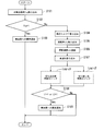
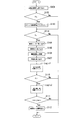
- the data of the water detection signal Sig is fetched (step S101), and whether or not the value of the water detection signal Sig is “1”, that is, the power detection sensor 37 determines the power steering. It is determined whether or not an abnormality of the device is detected (step S102), and if it is determined to be Yes, the driver notifies the abnormality of the vehicle, that is, the driver by lighting a warning light on the instrument panel of the vehicle. Is alerted (step S103), and this program ends.
- step S102 the steering torque signal Tr detected by the torque sensor 10 is taken (step S104), and the steering angle signal ⁇ s detected by the steering angle sensor 11 is further obtained. Capture (step S105). Subsequently, the steering angle signal ⁇ s captured in step S105 is time-differentiated to calculate the steering speed signal ⁇ s (step S106), and the vehicle speed signal Vs detected by the vehicle speed sensor 45 is captured (step S107). After that, the process proceeds to the cut-in determination logic Logic1 (see FIG. 12) and the switch-back determination logic Logic2 (see FIG. 13).
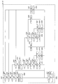
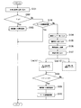
- step S201 it is determined whether or not the vehicle speed signal Vs is equal to or higher than a predetermined value Vx1 (15 km / h in the present embodiment) (step S201). If it is determined, it is determined whether an abnormality detection counter Cntr, which will be described later, is greater than or equal to a predetermined value Cntrx (“5” in the present embodiment) (step S210). When it is determined Yes in step S210, it is determined that an abnormality has occurred in the power steering apparatus, and after setting the cut-in determination logic abnormality determination flag L1 (step S211), it will be described later with reference to FIG. The process proceeds to step S108. On the other hand, when it is determined No, it is determined that the abnormality in the power steering apparatus has not been detected in the cutting determination logic Logic1, and the process proceeds to step S108.
- step S201 the vehicle speed signal Vs is 15 km / h or more
- the steering torque signal Tr is banded in a frequency band of 8 to 12 Hz, a frequency band of 20 to 25 Hz, and a frequency band of 40 to 50 Hz.
- the path filter process is performed (steps S202 to S204), and the peak level Trpl of the frequency component in each frequency band is calculated (step S205). Subsequently, it is determined whether or not the vehicle is traveling straight ahead (step S206).
- the steering torque signal Tr is smaller than a predetermined value Tx1 (1 Nm in the present embodiment), and the steering angle signal ⁇ s is a predetermined value ⁇ x1 (this embodiment). If the steering speed signal ⁇ s is smaller than a predetermined value ⁇ x1 (5 degrees / second in this embodiment), it is determined that the vehicle is traveling straight ahead.
- step S207 it is then determined whether the vehicle is traveling on a rough road.
- Trlx 0.5 Nm in the present embodiment
- step S207 When it is determined Yes in step S207, a good road counter Cntg described later is cleared (step S208), a good road running timer Tntg described later is cleared (step S209), and the process proceeds to step S210. .
- the good road running timer Tntg is incremented (step S212), and then the good road running timer Tntg is equal to or greater than a predetermined value Tntgx (2 seconds in this embodiment). It is determined whether or not (step S213). If it is determined No in step S213, the process directly proceeds to step S210. If it is determined Yes, the good road counter Cntg is incremented (step S214), and then the process proceeds to step S210.
- step S206 the absolute value of the steering speed signal ⁇ s is equal to or greater than the predetermined value ⁇ x1 (30 degrees) described above and the predetermined value ⁇ y1 (this embodiment). It is determined whether it is 90 degrees or less (step S215). If NO is determined, the process proceeds to step S210. If YES is determined, whether the good road counter Cntg is equal to or greater than a predetermined value Cntgx (“1” in the present embodiment). Judgment is made (step S216). If it is determined No in step S216, the process proceeds to step S210. If it is determined Yes, the process proceeds to step S217.
- step S217 it is determined whether or not all of the peak levels Trpl to Trpl3 are equal to or less than a predetermined value Trlx (0.5 Nm in this embodiment). If YES is determined, the abnormality detection counter Cntr is decremented or cleared (step S222), the abnormality detection timer Tntr is cleared (step S223), and the process proceeds to step S210.
- the peak levels Trpl1 and Trp3 of 8 to 12 Hz and 40 to 50 Hz are respectively equal to or less than the predetermined value Trplx (0.5 Nm), and the peak level Trpl2 of 20 to 25 Hz is the abnormality determination threshold value Trply It is determined whether or not (0.8 Nm in this embodiment) or more (step S218).
- step S218 the abnormality detection timer Tntr is cleared (step S223), and the process proceeds to step S210. If it is determined Yes, the abnormality detection timer Tntr is incremented. After (step S219), it is determined whether or not the abnormality detection timer Tntr is equal to or greater than a predetermined value Tntrx (0.5 seconds in the present embodiment) (step S220). Here, when it is determined No, the process directly proceeds to step S210, whereas when it is determined Yes, the abnormality detection counter Cntr is incremented (step S221), and then the process proceeds to step S210.
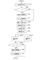
- step S301 it is determined whether or not the vehicle speed signal Vs is larger than a predetermined value Vx2 (15 km / h in the present embodiment) (step S301).
- the steering-holding steering torque signal Ts which will be described later, is returned to the default value Ds (“0” in the present embodiment), and the steering-torque releasing steering torque signal Td is set to the default value Dd (“0” in the present embodiment).
- step S331 after resetting the steering-holding steering torque capture flag Fs described later (step S332), it is determined whether or not the abnormality detection counter Cntr is equal to or greater than the predetermined value Cntrx (step S307).
- step S308 it is determined that an abnormality has occurred in the power steering apparatus, and after setting the switchback determination logic abnormality determination flag L2 (step S308), the operation will be described later shown in FIG. The process proceeds to step S108.
- step S108 it is determined that the abnormality in the power steering apparatus has not been detected in the switching determination logic Logic2, and the process proceeds to step S108.
- step S301 it is subsequently determined whether or not the absolute value of the steering angle signal ⁇ s is greater than a predetermined value ⁇ x2 (10 degrees in the present embodiment) (step S302). .
- step S302 If it is determined No in step S302, the steering-time steering torque signal Ts and the steering-release steering torque signal Td are returned to the default values Ds and Dd, respectively (step S331), and the steering-time steering torque is captured. After resetting the flag Fs (step S332), the process proceeds to step S307. On the other hand, if it is determined as Yes, whether or not the absolute value of the steering speed signal ⁇ s is smaller than a predetermined value ⁇ x2 (5 degrees / second in the present embodiment), that is, the steering wheel is in a steered state. It is determined whether the vehicle is in a steered state (step S303).
- a predetermined value ⁇ x2 5 degrees / second in the present embodiment
- step S304 it is determined whether or not the steering-time steering torque intake flag Fs is set.
- the steering torque signal Tr at that time is taken in as the steering-time steering torque signal Ts (step S305), and the steering-time steering torque fetch flag Fs is set (step S306). Then, the process proceeds to step S307.
- the determination is Yes it is assumed that the steering-time steering torque signal Ts has already been captured, and the process directly proceeds to step S307.
- step S303 it is determined whether or not the steering-time steering torque intake flag Fs is set as in step S304 (step S309).
- step S311 the process proceeds to step S331, whereas when it is determined Yes, the steering torque signal Tr at that time is taken in as the steering torque signal Td when the steering is released (step S310), After resetting the steering-time steering torque capture flag Fs (step S311), whether or not the steering-time steering torque signal Ts is 0 or more, that is, whether the steering wheel is steered rightward or leftward. Is determined (step S312).
- step S312 If YES (right steering) is determined in step S312, whether or not the steering-time steering torque signal Ts is greater than the steering-release steering torque signal Td, that is, from the steering state, It is determined whether the steering wheel is turned back (step S313).
- the steering-time steering torque signal Ts and the steering-release steering torque signal Td are returned to the default values Ds and Dd, respectively (step S321), and then step S307.
- step S314 After calculating the difference ⁇ Tt obtained by subtracting the steering torque signal Td at the time of steering release from the steering torque signal Ts at the time of steering (step S314), It is determined whether or not the absolute value of the difference ⁇ Tt is larger than the abnormality determination threshold value Tx (step S315).
- step S315 if it is determined Yes in step S315, the steering wheel is caught when returning from the steered state, and there is a high possibility that the power steering device is abnormal.
- the detection counter Cntr is incremented (step S316). Then, after the steering holding steering torque signal Ts and the steering holding releasing steering torque signal Td are returned to the default values Ds and Dd, respectively (step S317), the process proceeds to step S307.
- step S315 the steering-time steering torque signal Ts and the steering-release steering torque signal Td are returned to the default values Ds and Dd, respectively (step S318), and the steering-time steering torque is set.
- the capture flag Fs is reset (step S319), the abnormality detection counter Cntr is cleared (step S320), and the process proceeds to step S307.
- step S312 If it is determined No (leftward steering) in step S312, whether or not the steering-holding-release steering torque signal Td is larger than the steering-holding steering torque signal Ts, that is, the steering-holding state. It is then determined whether the steering wheel is turned back or turned (step S322). Here, when it is determined No (at the time of turning), the steering-time steering torque signal Ts and the steering-release steering torque signal Td are returned to the default values Ds and Dd, respectively (step S330), and then step S307. Migrate to On the other hand, if it is determined Yes (when switching back), a difference ⁇ Tt obtained by subtracting the steering-time steering torque signal Ts from the steering-release steering torque signal Td is calculated (step S324). Thereafter, an abnormality is determined based on the numerical value of the difference ⁇ Tt. Since the processes in steps S324 to S329 are the same as those in steps S315 to S320, detailed description thereof is omitted.
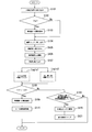
- step S108 shown in FIG. 11 it is determined whether or not an abnormality has been detected in at least one of the cutting time determination logic Logic1 and the switching back time determination logic Logic2 (step S108).
- the second abnormality determination unit 72 determines whether the power steering apparatus is abnormal based on the detection of water in the housing 3 by the water detection sensor 37.
- the first abnormality determination unit 71 detects the intrusion of foreign matter such as sand and dust that is difficult to detect by the water detection sensor 37 based on the steering information, and makes an abnormality determination of the power steering device in a multifaceted manner. An abnormality in the power steering device can be determined.
- the first abnormality determination unit 71 and the cutting time determination unit 77 that performs abnormality determination of the power steering device based on steering information under different steering conditions such as when cutting and when switching back. Since the return time determination unit 78 is provided, an appropriate abnormality determination can be performed for each steering condition.
- the abnormality determination unit 62 is provided with the first abnormality determination unit storage unit 82 and the second abnormality determination unit storage unit 83 in separate states. Even if an abnormality occurs in any one of 82 and 83, it is only necessary to reset the stored information in only one of the storage units, and the stored information in the other storage unit is not affected. As a result, the abnormality determination of the power steering device can be continuously performed by the abnormality determination unit on the other storage unit side without resetting the stored information in the other storage unit. Can be accelerated.
- the second abnormality determining unit 72 determines that the power steering apparatus is abnormal, water has entered the housing 3, and as time passes, rust increases and the steering load increases. There is a high possibility of going. In such a case, if the motor command signal Io is greatly increased and corrected as the steering load increases, the steering load becomes lighter, while the value of the detected steering torque signal Tr becomes smaller. There is a possibility that the abnormality determination by the one abnormality determination unit 71 cannot be performed satisfactorily.
- 14 to 16 are flowcharts of the abnormality determination control of the power steering apparatus according to the second embodiment of the present invention, and are based on the logic Logic1 and Logic2 in the abnormality determination control flow of the power steering apparatus of the first embodiment.
- This is a change in the method for determining abnormality.
- the configuration is basically the same as that of the first embodiment. Therefore, the same configuration (processing) as that of the first embodiment is denoted by the same reference numeral. Therefore, a specific description is omitted (the same as in the following embodiments).
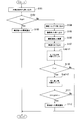
- step S102 it is determined as No in step S102 for determining whether or not the abnormality of the power steering device is detected by the water detection sensor 37. If it is determined, after taking in various signals (steps S104 to S107), the process proceeds to the cut-in determination logic Logic1.
- the steps S210 and S211 in the cutting time determination logic Logic1 of the first embodiment are abolished, and instead the abnormality detection timer Tntr in the step S220. Is determined to be greater than or equal to a predetermined value, the logic diagnosis continuation flag Ft is set (step S224), and the process proceeds to step S210. Furthermore, after clearing the abnormality detection timer Tntr in step S223, the logic diagnosis continuation flag Ft is reset and the process proceeds to step S210.
- step S110 when the process of the cut-in determination logic Logic1 is completed, it is subsequently determined whether or not the logic diagnosis continuation flag Ft is set (step S110). On the other hand, if YES is determined, the process proceeds to switch-back determination logic Logic2.
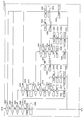
- the steps S307 and S308 in the switch-back determination logic Logic2 of the first embodiment are abolished, and instead the steps S317, S320, After the processing of S321, S326, S329, S330, and S332, processing for resetting the logic diagnosis continuation flag Ft set in Step S224 is added (Steps S333 to 339).
- step S111 when it is determined that the program ends, when it is determined that an abnormality has occurred in the power steering device, an abnormality is notified to the vehicle side (step S112), and then the program ends. To do.
- the cutting time determination unit 77 determines that the power steering device is in an abnormal state based on detection of a periodic change in the steering torque signal Tr, In addition, when it is determined that the power steering apparatus is in an abnormal state based on the amount of change in the steering torque signal Tr when the steering wheel switching section 78 switches back the steering wheel, it is determined that the power steering apparatus is abnormal. To do. As a result, the abnormality determination of the power steering device by the first abnormality determination unit 71 becomes more reliable, and erroneous determination can be suppressed.
- FIG. 17 is a flowchart of the abnormality determination control of the power steering apparatus according to the third embodiment of the present invention.
- a flag is set after water detection, and abnormality determination of the cut-in determination logic Logic1 and the switchback determination logic Logic2 is performed based on the presence or absence of the flag. It is.
- the data of the water detection signal Sig is fetched (step S101), and whether or not the value of the water detection signal Sig is “1”. That is, it is determined whether or not an abnormality of the power steering device has been detected by the water detection sensor 37 (step S102). If the determination is Yes, a logic diagnosis start flag Fu is set (step S113). On the other hand, the process proceeds to step S114, and if it is determined No, the process proceeds directly to step S114.
- step S114 it is determined whether the logic diagnosis start flag Fu is set. If it is determined No, the program ends. On the other hand, if Yes is determined, the process proceeds to step S104.
- the second abnormality determination unit 72 determines that the power steering device is in an abnormal state based on the detection of water in the housing 3, and the notch determination unit 77 determines the steering torque. Based on the detection of the periodic change of the signal Tr, the power steering device is determined to be in an abnormal state, and based on the amount of change in the steering torque signal Tr when the switching back time determination unit 78 switches back the steering wheel. When it is determined that the power steering apparatus is in an abnormal state, it is determined that the power steering apparatus is abnormal. Thereby, the abnormality determination of the power steering apparatus by the abnormality determination unit 71 becomes more reliable, and erroneous determination can be further suppressed.
- FIGS. 18 and 19 show a fourth embodiment of the power steering apparatus and the like according to the present invention, in which a steering assist force limiting function is added to the fail-safe processing unit 63 of the first embodiment.
- FIG. 18 is a control block diagram showing an arithmetic circuit configuration of the ECU 27 according to the fourth embodiment of the present invention.
- the fail-safe processing unit 63 limits the motor energization amount so that the value of the current flowing through the electric motor 26 is reduced.
- An energization amount limiting unit 85 is provided.
- the energization amount limiting unit 85 operates when at least one of the cutting time determination unit 77 and the switching back time determination unit 78 of the first abnormality determination unit 71 determines that the power steering device is abnormal.
- a command signal is transmitted to the limiter processing unit 65 so as to further limit the upper limit value of the motor command signal Io than normal, or the assist Map 68 of the motor command signal calculation unit 64 is set lower than normal.
- the motor energization amount is limited by changing the motor command signal Io to one that is calculated.
- FIG. 19 is a flowchart of abnormality determination control of the power steering apparatus according to the fourth embodiment of the present invention. That is, in this embodiment, when it is determined Yes in step S108 (when the abnormality is determined), after the abnormality is notified to the vehicle (step S109), the motor energization is performed by the means described above. The amount is limited (step S115), and the program ends.
- FIG. 20 shows a fifth embodiment of the power steering apparatus or the like according to the present invention.
- the cutting time determination logic Logic1 and the switching back The time determination logic Logic2 is determined to be abnormal.
- FIG. 20 is a flowchart of abnormality determination control of the power steering apparatus according to the fifth embodiment of the present invention. That is, in the flow of this embodiment, when it is determined No in step S102 (when abnormality is not detected by water detection), the limiter processing unit 65 subsequently limits the motor command signal Io. It is determined whether or not there is (step S116).
- step S116 the motor command signal Io by the limiter processing unit 65 itself is not considered without limiting the motor command signal Io performed by the energization amount limiting unit 85 according to the determination result of the first abnormality determination unit 71. Judgment is made based on whether or not the restriction is performed.
- step S116 the process proceeds to step S104.
- the abnormality determination of the power steering device is performed based on the logics Logic1 and Logic2, and it is determined Yes.
- the program ends without making an abnormality determination of the power steering apparatus by the logics Logic 1 and Logic 2 as they are.
- the steering assist force also decreases, so the steering load increases and the steering torque input to the steering wheel.
- the signal Tr is also large. In such a case, if the abnormality determination of the power steering device is performed by the first abnormality determination unit 71, an erroneous determination may be made.
- FIG. 21 shows a sixth embodiment of the power steering device or the like according to the present invention.
- each logic Logic1 depending on whether there is an abnormality after the water detection abnormality is determined.
- the logic Logic 1 and Logic 2 are judged to be abnormal after changing the Logic 2 threshold.
- FIG. 21 is a flowchart of abnormality determination control of the power steering apparatus according to the sixth embodiment of the present invention.
- step S102 for determining whether or not an abnormality has been detected by the water detection sensor 37 it is determined that either Yes or No is determined. Abnormal judgment is made by logic.
- step S102 when it is determined Yes in step S102, that is, when it is determined that water is detected by the water detection sensor 37, an abnormality is notified to the vehicle side (step S103).
- step S103 After the first abnormality determination unit 71 performs a process of lowering a determination threshold for determining an abnormality of the power steering device (step S117), the process proceeds to step S104.
- the determination threshold indicates the abnormality determination threshold Trply in the cut-in determination logic Logic1 and the abnormality determination threshold Tx in the switch-back determination logic Logic2.
- FIG. 22 is a flowchart of the abnormality determination control of the power steering apparatus according to the seventh embodiment of the present invention.
- step S117 is abolished and the motor energization amount is limited instead.
- Step S118 is added.
- the energization amount limiting unit 85 In the energization amount limiting unit 85 according to the present embodiment, only the first abnormality determination unit 71 is more than the limit value of the motor energization amount when the determination units 71 and 72 determine that the power steering device is abnormal.
- the limit value of the motor energization amount when it is determined that the power steering device is abnormal is set to be large.
- the limit value is set so that the motor energization amount becomes 37.5% when both the determination units 71 and 72 determine that both are abnormal.
- the limit value is set so that the motor energization amount is 50%.
- the cause of the abnormality is determined from the determination result. Can be guessed.
- both the first and second abnormality determining units 71 and 72 determine that the power steering apparatus is abnormal, water is intruded into the housing 3 and rust is generated.
- the first abnormality determination unit 71 determines that the power steering apparatus is abnormal, it can be estimated that foreign matter such as sand or dust has entered the housing 3.
- FIG. 23 is a flowchart of the abnormality determination control of the power steering apparatus according to the eighth embodiment of the present invention.
- step S117 is abolished, and No is determined in step S108. If it is determined, that is, if the abnormality is not confirmed by the logic, the process proceeds to step S119 to determine whether the water detection is correct or incorrect.
- step S119 whether or not a predetermined time has elapsed since the second abnormality determination unit 72 determined that the power steering device is abnormal based on the information stored in the second abnormality determination unit storage unit 83. Alternatively, it is determined whether or not the vehicle has been stopped and started a predetermined number of times. Here, when it is determined No, this program ends. On the other hand, when it is determined Yes, it is determined that the water detection sensor is abnormal (step S120), and the abnormality notification to the vehicle side is cleared. (Step S121), this program ends.
- the second abnormality determination unit 72 determines that the power steering apparatus is abnormal, water enters the housing 3 and rust is generated due to the intruded water, thereby causing the first abnormality. There is a high possibility that the abnormality determination unit 71 also determines that the power steering apparatus is abnormal.
- the second abnormality determination is performed. It is considered that there is an abnormality in the portion 72, or that the amount of water that has entered the housing 3 is very small and rust is not generated.
- the abnormality of the power steering device is determined based on the first abnormality determination unit 71 and the determination is made. Since the energization amount limiting unit 85 limits the energization amount of the motor based on the result, the inconvenience that the steering assist force is unnecessarily limited based on the determination of the second abnormality determination unit 72 in which an abnormality has occurred is avoided. it can. As a result, the continuity of the steering assist can be improved.
- the present invention is not limited to the configuration of each of the embodiments described above, and the configuration can be appropriately changed according to the specifications of the apparatus and the like without departing from the spirit of the invention.
- the abnormality determination control process of the power steering device by the first abnormality determination unit 71 is not limited to the control content as shown in the present embodiment, and the steering torque signal Tr and the motor when the steering operation is performed. What is necessary is that the abnormality of the power steering device can be determined based on the rotation speed N or the signal of the steering speed signal ⁇ s.
- the cutting time determination unit 77 performs band-pass filter processing on the steering torque signal Tr, and determines whether the signal within the predetermined frequency range of the steering torque signal Tr has a periodic change. It has been described that abnormality determination of the power steering device is performed by determining the above. However, when a periodic change is observed in the steering torque signal Tr, the motor rotation speed N and the steering speed signal ⁇ s are also changed periodically. It is also possible to provide an abnormality determination of the power steering device by the cutting time determination unit 77.
- the following modes can be considered.
- control device for the power steering device includes a steering mechanism that transmits the rotation of the steering wheel to the steered wheels, an electric motor that applies a steering force to the steering mechanism, and between the steering mechanism and the electric motor.
- a transmission mechanism that transmits the rotational force of the electric motor to the steering mechanism, a housing that houses at least a part of the steering mechanism, the transmission mechanism, and the electric motor, and is provided in the housing.
- a control device for a power steering apparatus comprising: a moisture detecting element that detects moisture in the housing; and a torque sensor that detects a steering torque generated in the steering mechanism, wherein the electric motor is based on the steering torque.
- a motor command signal calculation unit for calculating a motor command signal for driving and controlling a steering torque signal.
- a steering signal is received, a motor speed signal receiving unit to which a signal of the number of revolutions of the electric motor is input, a steering speed signal receiving unit to which a signal of the steering speed of the steering wheel is input, and a steering operation is performed.
- a first abnormality determination unit that determines that the power steering device is abnormal based on the steering torque, the rotation speed of the electric motor, or the steering speed signal, and the moisture detection element detects the moisture
- a second abnormality determination unit that determines that the power steering device is abnormal.
- the first abnormality determination unit is configured to receive a signal of the steering torque, the number of rotations of the motor, or the steering speed when the steering wheel is steered in the cutting direction.
- a cutting time determination unit that determines whether or not there is a periodic change within a frequency range, and the steering torque in a predetermined region including a region when the steering direction is switched from the cutting direction to the returning direction.
- a switchback time determination unit that detects a change, and determines that the power steering device is abnormal based on a determination result of the switchback time determination unit or the switchback time determination unit.
- the first abnormality determination unit is configured such that the cutting time determination unit detects the periodic change, and the switchback determination unit includes When it is determined that the change in the steering torque is greater than or equal to a predetermined value, it is determined that the power steering device is abnormal.
- the control device lights a vehicle warning light when the second abnormality determination unit determines that the power steering device is abnormal.
- the warning lamp lighting command signal output unit that outputs a command signal to be output and the first abnormality determination unit determine that the power steering device is abnormal
- the amount of current flowing is limited so that the value of the current flowing to the electric motor decreases.
- An energization amount limiting unit to be performed.
- the control device includes a command signal limiting unit that limits the motor command signal, and the first abnormality determination unit is configured to transmit the command When the signal restriction unit restricts the motor command signal, it does not determine whether the power steering apparatus is abnormal.
- the first abnormality determination unit determines that the power steering device is abnormal when the second abnormality determination unit determines that the power steering device is abnormal. Decrease the judgment threshold for judging that the device is abnormal.
- the control device stores a first abnormality determination that stores that the first abnormality determination unit has determined that the power steering device is abnormal.
- the information stored in the second abnormality determination unit storage unit is deleted, and the information stored in the first abnormality determination unit storage unit is not deleted.
- the motor command signal calculation unit determines that the power steering device is abnormal when the second abnormality determination unit determines that the power steering device is abnormal.
- the motor command signal is calculated so that the motor command signal actually output to the electric motor does not exceed the motor command signal calculated from the vehicle speed and the steering torque when the apparatus is normal.
- the control device causes a current flowing in the electric motor when the first abnormality determination unit determines that the power steering device is abnormal.
- An energization amount limiting unit that limits the energization amount so that the value decreases, and the energization amount limitation unit is determined when the first abnormality determination unit and the second abnormality determination unit determine that the power steering device is abnormal
- the energization amount is limited so that the energization amount limit value when the power steering apparatus is determined to be abnormal only by the first abnormality determination unit is larger than the energization amount limit value.
- the control device determines whether the power steering device is abnormal or not after the second abnormality determination unit determines that the predetermined time has elapsed or the vehicle If the first abnormality determination unit does not determine that the power steering device is abnormal even after the stop and start of the engine are repeated a predetermined number of times, it is determined that the determination by the second abnormality determination unit is an erroneous determination.
- the power steering apparatus is provided between a steering mechanism that transmits rotation of a steering wheel to steered wheels, an electric motor that applies a steering force to the steering mechanism, and the steering mechanism and the electric motor.
- a transmission mechanism that transmits the rotational force of the electric motor to the steering mechanism; a housing that houses at least a part of the steering mechanism, the transmission mechanism, and the electric motor; and a housing that is provided in the housing.
- a power steering device comprising: a moisture sensing element that senses moisture of the motor; a torque sensor that detects a steering torque generated in the steering mechanism; and a control device that drives and controls the electric motor.
- a motor command signal calculation unit for calculating a motor command signal for driving and controlling the electric motor based on the steering torque;
- a torque signal receiving unit to which the steering torque signal is input, a motor rotation number signal receiving unit to which the rotation number signal of the electric motor is input, and a steering speed signal to which the steering speed signal of the steering wheel is input A receiving unit, a first abnormality determining unit that determines that the power steering device is abnormal based on a signal of the steering torque when the steering operation is performed, the number of rotations of the electric motor, or the steering speed, and the moisture
- a second abnormality determination unit that determines that the power steering device is abnormal when the detection element detects moisture.
- the first abnormality determination unit is configured such that a signal of the steering torque, the number of rotations of the motor, or the steering speed when the steering wheel is steered in the cutting direction is within a predetermined frequency range. And detecting a change in the steering torque in a predetermined region including a region when the steering direction is switched from the turning direction to the turning back direction.
- a switchback time determination unit that determines that the power steering device is abnormal based on a determination result of the switchback time determination unit or the switchback time determination unit.
- the first abnormality determination unit is configured such that the cutting time determination unit detects the periodic change, and the switchback determination unit includes the steering torque. Is determined to be greater than or equal to a predetermined value, it is determined that the power steering apparatus is abnormal.
- the power steering apparatus instructs the vehicle warning light to be turned on when the second abnormality determination unit determines that the power steering apparatus is abnormal.
- the warning lamp lighting command signal output unit that outputs a signal and the first abnormality determination unit determine that the power steering device is abnormal
- the energization is performed so as to reduce the amount of current flowing through the electric motor.
- the power steering apparatus includes a command signal limiting unit that limits the motor command signal, and the first abnormality determination unit is configured to limit the command signal limit.
- the power steering device is not judged to be abnormal.
- the first abnormality determination unit determines that the power steering device is abnormal when the second abnormality determination unit determines that the power steering device is abnormal. Decrease threshold for determining.
- the power steering apparatus is for a first abnormality determination unit that stores that the first abnormality determination unit has determined that the power steering apparatus is abnormal.
- the information stored in the second abnormality determination unit storage unit is deleted, and the information stored in the first abnormality determination unit storage unit is not deleted.
- the motor command signal calculation unit determines that the power steering apparatus is normal when the second abnormality determination unit determines that the power steering apparatus is abnormal.
- the electric motor is driven and controlled so that the motor command signal actually output to the electric motor does not exceed the motor command signal calculated from the vehicle speed and the steering torque.
- the power steering apparatus has a current value flowing through the electric motor when the first abnormality determination unit determines that the abnormality is in the power steering apparatus.
- An energization amount limiting unit that limits the energization amount so as to decrease, and the energization amount limiting unit energizes when the first abnormality determination unit and the second abnormality determination unit determine that the power steering device is abnormal
- the energization amount is limited so that the energization amount limit value when the power steering device is determined to be abnormal only by the first abnormality determination unit is larger than the amount limit value.
- the power steering apparatus is determined to have an abnormality of the power steering apparatus by the second abnormality determination unit, or a predetermined time elapses or the vehicle is stopped.
- the first abnormality determination unit does not determine that the power steering device is abnormal even after the start is repeated a predetermined number of times, it is determined that the determination by the second abnormality determination unit is an erroneous determination.
Landscapes
- Engineering & Computer Science (AREA)
- Chemical & Material Sciences (AREA)
- Combustion & Propulsion (AREA)
- Transportation (AREA)
- Mechanical Engineering (AREA)
- Steering Control In Accordance With Driving Conditions (AREA)
- Power Steering Mechanism (AREA)
Abstract
Description
〔第1実施形態〕
まず、図1~図5に基づいて前記パワーステアリング装置のシステム構成について説明する。
〔第1実施形態の作用効果〕
以上のように構成されたパワーステアリング装置等によれば、前記第2異常判断部72が前記水検出センサ37による前記ハウジング3内の水の検出に基づいて前記パワーステアリング装置の異常判断を行う一方、前記第1異常判断部71が前記水検出センサ37による検出が困難な砂や埃等の異物の侵入を操舵情報に基づき検出して前記パワーステアリング装置の異常判断を行うことによって、多面的にパワーステアリング装置の異常を判断することができる。
〔第2実施形態〕
図14~16は、本発明の第2実施形態に係るパワーステアリング装置の異常判断制御のフローチャートであって、前記第1実施形態のパワーステアリング装置の異常判断制御フローにおける前記各ロジックLogic1,Logic2による異常の確定方法を変更したものである。なお、本実施形態では、フローの一部が変わるのみで、基本的には前記第1実施形態と同じ構成であるから、該第1実施形態と同じ構成(処理)については同一の符号を付すことにより、具体的な説明は省略する(以下の各実施形態に同じ)。
〔第3実施形態〕
図17は、本発明の第3実施形態に係るパワーステアリング装置の異常判断制御のフローチャートである。
〔第4実施形態〕
図18及び図19は、本発明に係るパワーステアリング装置等の第4実施形態を示し、前記第1実施形態のフェイルセーフ処理部63に操舵アシスト力の制限機能を追加したものである。
〔第5実施形態〕
図20は、本発明に係るパワーステアリング装置等の第5実施形態を示し、第4実施形態に係る制御内容において、水検出後にリミッタ処理の有無を判断したうえで切り込み時判断ロジックLogic1及び切り戻し時判断ロジックLogic2の異常判断を行うこととしたものである。
〔第6実施形態〕
図21は、本発明に係るパワーステアリング装置等の第6実施形態を示し、前記第4実施形態に係る異常判断の制御内容において、水検出の異常判断後、異常の有無により前記各ロジックLogic1,Logic2の閾値を変更したうえで該各ロジックLogic1,Logic2の異常判断を行うこととしたものである。
〔第7実施形態〕
図22は、本発明の第7実施形態に係るパワーステアリング装置の異常判断制御のフローチャートであって、前記第6実施形態に係る異常判断において、ステップS117を廃止し、代わりにモータ通電量を制限するステップS118を追加したものである。
〔第8実施形態〕
図23は、本発明の第8実施形態に係るパワーステアリング装置の異常判断制御のフローチャートであって、前記第6実施形態に係る異常判断制御において、ステップS117を廃止すると共に、ステップS108においてNoと判断された場合、すなわちロジックによる異常の確定がなされなかった場合には、ステップS119へ移行して水検出の判断の正誤を判断するようした。
Claims (20)
- ステアリングホイールの回転を転舵輪に伝達する操舵機構と、
前記操舵機構に操舵力を付与する電動モータと、
前記操舵機構と前記電動モータの間に設けられ、該電動モータの回転力を前記操舵機構に伝達する伝達機構と、
前記操舵機構の少なくとも一部、前記伝達機構、および前記電動モータを収容するハウジングと、
前記ハウジング内に設けられ、該ハウジング内の水分を検知する水分検知素子と、
前記操舵機構に発生する操舵トルクを検出するトルクセンサと、
を備えたパワーステアリング装置の制御装置であって、
前記操舵トルクに基づき、前記電動モータを駆動制御するモータ指令信号を演算するモータ指令信号演算部と、
前記操舵トルクの信号が入力されるトルク信号受信部と、
前記電動モータの回転数の信号が入力されるモータ回転数信号受信部と、
前記ステアリングホイールの操舵速度の信号が入力される操舵速度信号受信部と、
操舵操作が行われているときの前記操舵トルク、前記電動モータの回転数、または前記操舵速度の信号に基づき前記パワーステアリング装置の異常と判断する第1異常判断部と、
前記水分検知素子が水分を検知したとき前記パワーステアリング装置の異常と判断する第2異常判断部と、
を有することを特徴とするパワーステアリング装置の制御装置。 - 請求項1に記載のパワーステアリング装置の制御装置において、
前記第1異常判断部は、前記ステアリングホイールを切り込み方向に操舵操作するときの前記操舵トルク、前記モータの回転数、または前記操舵速度の信号が所定周波数範囲内において周期的な変化を有するか否かを判断する切り込み時判断部と、前記ステアリングホイールを切り込み方向から切り戻し方向へ操舵方向を切り換えたときの領域を含む所定領域における前記操舵トルクの変化を検出する切り戻し時判断部と、を備え、前記切り込み時判断部または前記切り戻し時判断部の判断結果に基づき前記パワーステアリング装置の異常と判断することを特徴とするパワーステアリング装置の制御装置。 - 請求項2に記載のパワーステアリング装置の制御装置において、
前記第1異常判断部は、前記切り込み時判断部が前記周期的な変化を検出し、かつ前記切り戻し判断部が前記操舵トルクの変化が所定値以上であると判断したとき、前記パワーステアリング装置の異常と判断することを特徴とするパワーステアリング装置の制御装置。 - 請求項1に記載のパワーステアリング装置の制御装置は、前記第2異常判断部が前記パワーステアリング装置の異常と判断したとき、車両の警告灯を点灯させる指令信号を出力する警告灯点灯指令信号出力部と、前記第1異常判断部が前記パワーステアリング装置の異常と判断するとき、前記電動モータに流れる電流値が減少するように通電量の制限を行う通電量制限部と、を有することを特徴とするパワーステアリング装置の制御装置。
- 請求項1に記載のパワーステアリング装置の制御装置は、前記モータ指令信号を制限する指令信号制限部を備え、
前記第1異常判断部は、前記指令信号制限部が前記モータ指令信号の制限を行っているとき、前記パワーステアリング装置の異常の判断を行わないことを特徴とするパワーステアリング装置の制御装置。 - 請求項1に記載のパワーステアリング装置の制御装置において、
前記第1異常判断部は、前記第2異常判断部が前記パワーステアリング装置の異常と判断したとき、前記パワーステアリング装置の異常と判断するための判断閾値を下げることを特徴とするパワーステアリング装置の制御装置。 - 請求項1に記載のパワーステアリング装置の制御装置は、前記第1異常判断部が前記パワーステアリング装置の異常と判断したことを記憶する第1異常判断部用記憶部と、前記第2異常判断部が前記パワーステアリング装置の異常と判断したことを記憶する第2異常判断部用記憶部を備え、
前記第2異常判断部用記憶部に異常が生じたとき、前記第2異常判断部用記憶部に記憶された情報を消去し前記第1異常判断部用記憶部に記憶された情報は消去しないことを特徴とするパワーステアリング装置の制御装置。 - 請求項1に記載のパワーステアリング装置の制御装置において、
前記モータ指令信号演算部は、前記第2異常判断部が前記パワーステアリング装置の異常と判断したとき、前記パワーステアリング装置の正常時に車両速度および前記操舵トルクから演算される前記モータ指令信号よりも実際に前記電動モータに出力される前記モータ指令信号が上回らないようにモータ指令信号を演算することを特徴とするパワーステアリング装置の制御装置。 - 請求項1に記載のパワーステアリング装置の制御装置は、前記第1異常判断部が前記パワーステアリング装置の異常と判断するとき、前記電動モータに流れる電流値が減少するように通電量の制限を行う通電量制限部を備え、
前記通電量制限部は、前記第1異常判断部および前記第2異常判断部が前記パワーステアリング装置の異常と判断したときの通電量の制限値よりも前記第1異常判断部のみで前記パワーステアリング装置の異常と判断したときの通電量の制限値が大きくなるように通電量の制限を行うことを特徴とするパワーステアリング装置の制御装置。 - 請求項1に記載のパワーステアリング装置の制御装置は、前記第2異常判断部で前記パワーステアリング装置の異常と判断された後、所定時間経過または車両の停止および始動が所定回数繰り返された後においても前記第1異常判断部において前記パワーステアリング装置の異常と判断されないとき、前記第2異常判断部による判断が誤判断であると判断することを特徴とするパワーステアリング装置の制御装置。
- ステアリングホイールの回転を転舵輪に伝達する操舵機構と、
前記操舵機構に操舵力を付与する電動モータと、
前記操舵機構と前記電動モータの間に設けられ、該電動モータの回転力を前記操舵機構に伝達する伝達機構と、
前記操舵機構の少なくとも一部、前記伝達機構、および前記電動モータを収容するハウジングと、
前記ハウジング内に設けられ、該ハウジング内の水分を検知する水分検知素子と、
前記操舵機構に発生する操舵トルクを検出するトルクセンサと、
前記電動モータを駆動制御する制御装置と、を備えたパワーステアリング装置であって、
前記制御装置は、
前記操舵トルクに基づき、前記電動モータを駆動制御するモータ指令信号を演算するモータ指令信号演算部と、
前記操舵トルクの信号が入力されるトルク信号受信部と、
前記電動モータの回転数の信号が入力されるモータ回転数信号受信部と、
前記ステアリングホイールの操舵速度の信号が入力される操舵速度信号受信部と、
操舵操作が行われているときの前記操舵トルク、前記電動モータの回転数、または前記操舵速度の信号に基づき前記パワーステアリング装置の異常と判断する第1異常判断部と、
前記水分検知素子が水分を検知したとき前記パワーステアリング装置の異常と判断する第2異常判断部と、
を有することを特徴とするパワーステアリング装置。 - 請求項11に記載のパワーステアリング装置において、
前記第1異常判断部は、前記ステアリングホイールを切り込み方向に操舵操作するときの前記操舵トルク、前記モータの回転数、または前記操舵速度の信号が所定周波数範囲内において周期的な変化を有するか否かを判断する切り込み時判断部と、前記ステアリングホイールを切り込み方向から切り戻し方向へ操舵方向を切り換えたときの領域を含む所定領域における前記操舵トルクの変化を検出する切り戻し時判断部と、を備え、前記切り込み時判断部または前記切り戻し時判断部の判断結果に基づき前記パワーステアリング装置の異常と判断することを特徴とするパワーステアリング装置。 - 請求項12に記載のパワーステアリング装置において、
前記第1異常判断部は、前記切り込み時判断部が前記周期的な変化を検出し、かつ前記切り戻し判断部が前記操舵トルクの変化が所定値以上であると判断したとき、前記パワーステアリング装置の異常と判断することを特徴とするパワーステアリング装置。 - 請求項11に記載のパワーステアリング装置は、前記第2異常判断部が前記パワーステアリング装置の異常と判断したとき、車両の警告灯を点灯させる指令信号を出力する警告灯点灯指令信号出力部と、前記第1異常判断部が前記パワーステアリング装置の異常と判断するとき、前記電動モータに流れる電流値が減少するように通電量の制限を行う通電量制限部と、を有することを特徴とするパワーステアリング装置。
- 請求項11に記載のパワーステアリング装置は、前記モータ指令信号を制限する指令信号制限部を備え、
前記第1異常判断部は、前記指令信号制限部が前記モータ指令信号の制限を行っているとき、前記パワーステアリング装置の異常の判断を行わないことを特徴とするパワーステアリング装置。 - 請求項11に記載のパワーステアリング装置において、
前記第1異常判断部は、前記第2異常判断部が前記パワーステアリング装置の異常と判断したとき、前記パワーステアリング装置の異常と判断するための判断閾値を下げることを特徴とするパワーステアリング装置。 - 請求項11に記載のパワーステアリング装置は、前記第1異常判断部が前記パワーステアリング装置の異常と判断したことを記憶する第1異常判断部用記憶部と、前記第2異常判断部が前記パワーステアリング装置の異常と判断したことを記憶する第2異常判断部用記憶部を備え、
前記第2異常判断部用記憶部に異常が生じたとき、前記第2異常判断部用記憶部に記憶された情報を消去し前記第1異常判断部用記憶部に記憶された情報は消去しないことを特徴とするパワーステアリング装置。 - 請求項11に記載のパワーステアリング装置において、前記モータ指令信号演算部は、前記第2異常判断部が前記パワーステアリング装置の異常と判断したとき、前記パワーステアリング装置の正常時に車両速度および前記操舵トルクから演算される前記モータ指令信号よりも実際に前記電動モータに出力される前記モータ指令信号が上回らないように前記電動モータを駆動制御することを特徴とするパワーステアリング装置。
- 請求項11に記載のパワーステアリング装置は、前記第1異常判断部が前記パワーステアリング装置の異常と判断するとき、前記電動モータに流れる電流値が減少するように通電量の制限を行う通電量制限部を備え、
前記通電量制限部は、前記第1異常判断部および前記第2異常判断部が前記パワーステアリング装置の異常と判断したときの通電量の制限値よりも前記第1異常判断部のみで前記パワーステアリング装置の異常と判断したときの通電量の制限値が大きくなるように通電量の制限を行うことを特徴とするパワーステアリング装置。 - 請求項1に記載のパワーステアリング装置は、前記第2異常判断部で前記パワーステアリング装置の異常と判断された後、所定時間経過または車両の停止および始動が所定回数繰り返された後においても前記第1異常判断部において前記パワーステアリング装置の異常と判断されないとき、前記第2異常判断部による判断が誤判断であると判断することを特徴とするパワーステアリング装置。
Priority Applications (5)
| Application Number | Priority Date | Filing Date | Title |
|---|---|---|---|
| KR1020187000187A KR102003172B1 (ko) | 2015-07-08 | 2016-05-16 | 파워 스티어링 장치 및 파워 스티어링 장치의 제어 장치 |
| DE112016003083.5T DE112016003083T5 (de) | 2015-07-08 | 2016-05-16 | Servolenkungsvorrichtung und Vorrichtung zum Steuern einer Servolenkungsvorrichtung |
| JP2017527109A JP6472518B2 (ja) | 2015-07-08 | 2016-05-16 | パワーステアリング装置及びパワーステアリング装置の制御装置 |
| US15/742,104 US10399594B2 (en) | 2015-07-08 | 2016-05-16 | Power steering device and device for controlling power steering device |
| CN201680039455.1A CN107735310B (zh) | 2015-07-08 | 2016-05-16 | 动力转向装置以及动力转向装置的控制装置 |
Applications Claiming Priority (2)
| Application Number | Priority Date | Filing Date | Title |
|---|---|---|---|
| JP2015-136565 | 2015-07-08 | ||
| JP2015136565 | 2015-07-08 |
Publications (1)
| Publication Number | Publication Date |
|---|---|
| WO2017006623A1 true WO2017006623A1 (ja) | 2017-01-12 |
Family
ID=57685100
Family Applications (1)
| Application Number | Title | Priority Date | Filing Date |
|---|---|---|---|
| PCT/JP2016/064478 Ceased WO2017006623A1 (ja) | 2015-07-08 | 2016-05-16 | パワーステアリング装置及びパワーステアリング装置の制御装置 |
Country Status (6)
| Country | Link |
|---|---|
| US (1) | US10399594B2 (ja) |
| JP (1) | JP6472518B2 (ja) |
| KR (1) | KR102003172B1 (ja) |
| CN (1) | CN107735310B (ja) |
| DE (1) | DE112016003083T5 (ja) |
| WO (1) | WO2017006623A1 (ja) |
Cited By (8)
| Publication number | Priority date | Publication date | Assignee | Title |
|---|---|---|---|---|
| WO2017145599A1 (ja) * | 2016-02-24 | 2017-08-31 | 日立オートモティブシステムズ株式会社 | パワーステアリング装置 |
| WO2018197147A1 (de) * | 2017-04-27 | 2018-11-01 | Volkswagen Aktiengesellschaft | Steuerung eines lenksystems zur bedarfsweisen bereitstellung einer lenkkraft und/oder eines lenkmoments |
| JP2019099111A (ja) * | 2017-12-08 | 2019-06-24 | 株式会社ジェイテクト | ステアリング装置 |
| JP2022081301A (ja) * | 2020-11-19 | 2022-05-31 | 株式会社ジェイテクト | 異常検出装置 |
| US11420673B2 (en) * | 2017-07-03 | 2022-08-23 | Robert Bosch Gmbh | Method for operating a steering system, and steering system |
| US20240227923A9 (en) * | 2022-10-19 | 2024-07-11 | Jtekt Corporation | Vehicle power supply system and control method of vehicle power supply system |
| US20250058825A1 (en) * | 2022-01-13 | 2025-02-20 | Robert Bosch Gmbh | Method for Operating a Steering System |
| US12709324B2 (en) * | 2022-01-13 | 2026-08-18 | Robert Bosch Gmbh | Method for operating a steering system |
Families Citing this family (16)
| Publication number | Priority date | Publication date | Assignee | Title |
|---|---|---|---|---|
| DE102015102228A1 (de) * | 2015-02-17 | 2016-08-18 | Robert Bosch Automotive Steering Gmbh | Lenksystem für ein kraftfahrzeug |
| DE102015115118A1 (de) * | 2015-09-09 | 2017-03-09 | Robert Bosch Automotive Steering Gmbh | Vorrichtung zum betreiben eines lenksystems, lenksystem, verfahren |
| JP6467670B2 (ja) * | 2015-11-04 | 2019-02-13 | 日立オートモティブシステムズ株式会社 | パワーステアリング装置、およびパワーステアリング装置の制御装置 |
| JP6580258B2 (ja) * | 2016-05-24 | 2019-09-25 | 三菱電機株式会社 | 電子制御装置及びその動作制御方法 |
| DE112017003824B4 (de) * | 2016-11-03 | 2025-01-02 | Robert Bosch Gmbh | Erkennung von hoher Reibung in einem Servolektric-Lenkgetriebe aufgrund von Rost |
| KR101950259B1 (ko) * | 2017-05-22 | 2019-02-22 | 주식회사 만도 | 전동식 조향장치의 조향정보 검출 장치 및 조향정보 검출방법 |
| US11137314B2 (en) * | 2018-03-07 | 2021-10-05 | Steering Solutions Ip Holding Corporation | Water intrusion detection |
| DE102019115867A1 (de) * | 2019-06-11 | 2020-12-17 | Zf Automotive Germany Gmbh | Lenkvorrichtung für ein Kraftfahrzeug |
| KR102745130B1 (ko) * | 2020-05-06 | 2024-12-23 | 현대모비스 주식회사 | 전동식 조향시스템의 제어 장치 및 방법 |
| CN112158257A (zh) * | 2020-09-03 | 2021-01-01 | 中国第一汽车股份有限公司 | 一种l4级别自动驾驶车辆用转角传感器 |
| KR102910609B1 (ko) * | 2021-07-12 | 2026-01-12 | 에이치엘만도 주식회사 | 부츠 손상 감지 장치 및 방법 |
| FR3128755B1 (fr) * | 2021-10-28 | 2023-11-24 | Trelleborg Carquefou | soufflet de direction |
| US12139215B1 (en) * | 2022-01-11 | 2024-11-12 | Waymo Llc | Method for detection and mitigation of blocked steering actuator |
| KR20240053782A (ko) * | 2022-10-18 | 2024-04-25 | 에이치엘만도 주식회사 | 조향 제어 장치 및 제어 방법 |
| KR20240169448A (ko) * | 2023-05-24 | 2024-12-03 | 에이치엘만도 주식회사 | 조향 시스템의 모터 제어 장치 및 이에 의한 모터 제어 방법 |
| CN117799691B (zh) * | 2024-02-29 | 2024-06-14 | 中国第一汽车股份有限公司 | 电动助力转向卡滞的监测方法、系统及其车辆 |
Citations (4)
| Publication number | Priority date | Publication date | Assignee | Title |
|---|---|---|---|---|
| JP2006130959A (ja) * | 2004-11-02 | 2006-05-25 | Nsk Ltd | 電動パワーステアリング装置 |
| JP2008037255A (ja) * | 2006-08-07 | 2008-02-21 | Toyota Motor Corp | 電動パワーステアリング装置 |
| JP2008178270A (ja) * | 2007-01-22 | 2008-07-31 | Suzuki Motor Corp | 電源制御システム |
| JP2014234102A (ja) * | 2013-06-04 | 2014-12-15 | 株式会社ジェイテクト | ステアリング装置 |
Family Cites Families (7)
| Publication number | Priority date | Publication date | Assignee | Title |
|---|---|---|---|---|
| JP2005059795A (ja) * | 2003-08-19 | 2005-03-10 | Toyoda Mach Works Ltd | 電気式動力舵取装置 |
| JP2006044437A (ja) * | 2004-08-04 | 2006-02-16 | Nsk Ltd | 電動パワーステアリング装置 |
| EP1878638B1 (en) * | 2006-07-14 | 2009-12-30 | NSK Ltd. | Control apparatus for electric power steering |
| JP2009023402A (ja) * | 2007-07-17 | 2009-02-05 | Toyota Motor Corp | ステアリング装置 |
| JP5387989B2 (ja) * | 2009-12-25 | 2014-01-15 | 株式会社デンソー | 電動機駆動装置、および、これを用いた電動パワーステアリング装置 |
| CN103192870A (zh) * | 2012-01-09 | 2013-07-10 | 江苏罡阳动力转向器厂 | 一种电动助力转向控制器 |
| WO2014115275A1 (ja) * | 2013-01-24 | 2014-07-31 | トヨタ自動車株式会社 | 車両の電動パワーステアリング装置 |
-
2016
- 2016-05-16 CN CN201680039455.1A patent/CN107735310B/zh active Active
- 2016-05-16 US US15/742,104 patent/US10399594B2/en active Active
- 2016-05-16 WO PCT/JP2016/064478 patent/WO2017006623A1/ja not_active Ceased
- 2016-05-16 JP JP2017527109A patent/JP6472518B2/ja active Active
- 2016-05-16 DE DE112016003083.5T patent/DE112016003083T5/de not_active Ceased
- 2016-05-16 KR KR1020187000187A patent/KR102003172B1/ko active Active
Patent Citations (4)
| Publication number | Priority date | Publication date | Assignee | Title |
|---|---|---|---|---|
| JP2006130959A (ja) * | 2004-11-02 | 2006-05-25 | Nsk Ltd | 電動パワーステアリング装置 |
| JP2008037255A (ja) * | 2006-08-07 | 2008-02-21 | Toyota Motor Corp | 電動パワーステアリング装置 |
| JP2008178270A (ja) * | 2007-01-22 | 2008-07-31 | Suzuki Motor Corp | 電源制御システム |
| JP2014234102A (ja) * | 2013-06-04 | 2014-12-15 | 株式会社ジェイテクト | ステアリング装置 |
Cited By (12)
| Publication number | Priority date | Publication date | Assignee | Title |
|---|---|---|---|---|
| WO2017145599A1 (ja) * | 2016-02-24 | 2017-08-31 | 日立オートモティブシステムズ株式会社 | パワーステアリング装置 |
| JPWO2017145599A1 (ja) * | 2016-02-24 | 2018-11-29 | 日立オートモティブシステムズ株式会社 | パワーステアリング装置 |
| US10858037B2 (en) | 2016-02-24 | 2020-12-08 | Hitachi Automotive Systems, Ltd. | Power steering device |
| WO2018197147A1 (de) * | 2017-04-27 | 2018-11-01 | Volkswagen Aktiengesellschaft | Steuerung eines lenksystems zur bedarfsweisen bereitstellung einer lenkkraft und/oder eines lenkmoments |
| US11420673B2 (en) * | 2017-07-03 | 2022-08-23 | Robert Bosch Gmbh | Method for operating a steering system, and steering system |
| JP2019099111A (ja) * | 2017-12-08 | 2019-06-24 | 株式会社ジェイテクト | ステアリング装置 |
| JP2022081301A (ja) * | 2020-11-19 | 2022-05-31 | 株式会社ジェイテクト | 異常検出装置 |
| JP7552284B2 (ja) | 2020-11-19 | 2024-09-18 | 株式会社ジェイテクト | 異常検出装置 |
| US20250058825A1 (en) * | 2022-01-13 | 2025-02-20 | Robert Bosch Gmbh | Method for Operating a Steering System |
| US12709324B2 (en) * | 2022-01-13 | 2026-08-18 | Robert Bosch Gmbh | Method for operating a steering system |
| US20240227923A9 (en) * | 2022-10-19 | 2024-07-11 | Jtekt Corporation | Vehicle power supply system and control method of vehicle power supply system |
| US12466471B2 (en) * | 2022-10-19 | 2025-11-11 | Jtekt Corporation | Vehicle power supply system and control method of vehicle power supply system |
Also Published As
| Publication number | Publication date |
|---|---|
| US20180194390A1 (en) | 2018-07-12 |
| CN107735310B (zh) | 2019-12-03 |
| KR102003172B1 (ko) | 2019-07-23 |
| US10399594B2 (en) | 2019-09-03 |
| KR20180015236A (ko) | 2018-02-12 |
| CN107735310A (zh) | 2018-02-23 |
| JP6472518B2 (ja) | 2019-02-20 |
| JPWO2017006623A1 (ja) | 2018-04-19 |
| DE112016003083T5 (de) | 2018-04-05 |
Similar Documents
| Publication | Publication Date | Title |
|---|---|---|
| JP6472518B2 (ja) | パワーステアリング装置及びパワーステアリング装置の制御装置 | |
| JP6467670B2 (ja) | パワーステアリング装置、およびパワーステアリング装置の制御装置 | |
| JP6608919B2 (ja) | パワーステアリングにおける運転支援機能の安全確保 | |
| US7878512B2 (en) | Alignment changing control device | |
| US9637167B2 (en) | Steering control device, and steering control method | |
| JP5945764B2 (ja) | パワーステアリング装置 | |
| JP3777398B2 (ja) | 車両用操舵制御装置 | |
| JP6375545B2 (ja) | パワーステアリング装置およびパワーステアリング装置の制御回路 | |
| JP5648574B2 (ja) | 車両用電源制御装置 | |
| JP2005335432A (ja) | 後輪転舵制御装置 | |
| WO2017159037A1 (ja) | パワーステアリング装置の制御装置 | |
| CN108093676B (zh) | 动力转向装置的控制装置及动力转向装置 | |
| JP6825250B2 (ja) | 車載システム | |
| CN103935394B (zh) | 转向控制装置 | |
| JP5416722B2 (ja) | 電動パワーステアリング装置 | |
| JP4719901B2 (ja) | 後輪操舵角制御装置 | |
| JP5428634B2 (ja) | 電動パワーステアリング装置の制御装置 | |
| JPH0787603A (ja) | 電気自動車の保護装置 | |
| JP3541867B2 (ja) | 舵角センサ異常検出装置およびこれを備えた車輌 | |
| JP5181617B2 (ja) | 車両用電源装置 | |
| JP2009113760A (ja) | 電動パワーステアリング装置の制御装置及びモータの制御装置 | |
| JP3840721B2 (ja) | 電動式パワーステアリングの制御装置 | |
| JP3229519B2 (ja) | 電動式パワーステアリング装置 | |
| JPH06312668A (ja) | 車両の後輪操舵装置 | |
| JP3759868B2 (ja) | 電動パワーステアリング装置 |
Legal Events
| Date | Code | Title | Description |
|---|---|---|---|
| 121 | Ep: the epo has been informed by wipo that ep was designated in this application |
Ref document number: 16821094 Country of ref document: EP Kind code of ref document: A1 |
|
| ENP | Entry into the national phase |
Ref document number: 20187000187 Country of ref document: KR Kind code of ref document: A |
|
| ENP | Entry into the national phase |
Ref document number: 2017527109 Country of ref document: JP Kind code of ref document: A |
|
| WWE | Wipo information: entry into national phase |
Ref document number: 112016003083 Country of ref document: DE |
|
| 122 | Ep: pct application non-entry in european phase |
Ref document number: 16821094 Country of ref document: EP Kind code of ref document: A1 |