WO2017002971A1 - 硫化物固体電解質材料、電池および硫化物固体電解質材料の製造方法 - Google Patents
硫化物固体電解質材料、電池および硫化物固体電解質材料の製造方法 Download PDFInfo
- Publication number
- WO2017002971A1 WO2017002971A1 PCT/JP2016/069713 JP2016069713W WO2017002971A1 WO 2017002971 A1 WO2017002971 A1 WO 2017002971A1 JP 2016069713 W JP2016069713 W JP 2016069713W WO 2017002971 A1 WO2017002971 A1 WO 2017002971A1
- Authority
- WO
- WIPO (PCT)
- Prior art keywords
- solid electrolyte
- sulfide solid
- electrolyte material
- electrode active
- tetrahedron
- Prior art date
- Legal status (The legal status is an assumption and is not a legal conclusion. Google has not performed a legal analysis and makes no representation as to the accuracy of the status listed.)
- Ceased
Links
Images






Classifications
-
- H—ELECTRICITY
- H01—ELECTRIC ELEMENTS
- H01M—PROCESSES OR MEANS, e.g. BATTERIES, FOR THE DIRECT CONVERSION OF CHEMICAL ENERGY INTO ELECTRICAL ENERGY
- H01M10/00—Secondary cells; Manufacture thereof
- H01M10/05—Accumulators with non-aqueous electrolyte
- H01M10/056—Accumulators with non-aqueous electrolyte characterised by the materials used as electrolytes, e.g. mixed inorganic/organic electrolytes
- H01M10/0561—Accumulators with non-aqueous electrolyte characterised by the materials used as electrolytes, e.g. mixed inorganic/organic electrolytes the electrolyte being constituted of inorganic materials only
- H01M10/0562—Solid materials
-
- C—CHEMISTRY; METALLURGY
- C01—INORGANIC CHEMISTRY
- C01B—NON-METALLIC ELEMENTS; COMPOUNDS THEREOF; METALLOIDS OR COMPOUNDS THEREOF NOT COVERED BY SUBCLASS C01C
- C01B33/00—Silicon; Compounds thereof
- C01B33/20—Silicates
- C01B33/32—Alkali metal silicates
-
- H—ELECTRICITY
- H01—ELECTRIC ELEMENTS
- H01B—CABLES; CONDUCTORS; INSULATORS; SELECTION OF MATERIALS FOR THEIR CONDUCTIVE, INSULATING OR DIELECTRIC PROPERTIES
- H01B1/00—Conductors or conductive bodies characterised by the conductive materials; Selection of materials as conductors
- H01B1/06—Conductors or conductive bodies characterised by the conductive materials; Selection of materials as conductors mainly consisting of other non-metallic substances
- H01B1/10—Conductors or conductive bodies characterised by the conductive materials; Selection of materials as conductors mainly consisting of other non-metallic substances sulfides
-
- H—ELECTRICITY
- H01—ELECTRIC ELEMENTS
- H01M—PROCESSES OR MEANS, e.g. BATTERIES, FOR THE DIRECT CONVERSION OF CHEMICAL ENERGY INTO ELECTRICAL ENERGY
- H01M10/00—Secondary cells; Manufacture thereof
- H01M10/05—Accumulators with non-aqueous electrolyte
- H01M10/052—Li-accumulators
-
- H—ELECTRICITY
- H01—ELECTRIC ELEMENTS
- H01M—PROCESSES OR MEANS, e.g. BATTERIES, FOR THE DIRECT CONVERSION OF CHEMICAL ENERGY INTO ELECTRICAL ENERGY
- H01M10/00—Secondary cells; Manufacture thereof
- H01M10/05—Accumulators with non-aqueous electrolyte
- H01M10/052—Li-accumulators
- H01M10/0525—Rocking-chair batteries, i.e. batteries with lithium insertion or intercalation in both electrodes; Lithium-ion batteries
-
- H—ELECTRICITY
- H01—ELECTRIC ELEMENTS
- H01M—PROCESSES OR MEANS, e.g. BATTERIES, FOR THE DIRECT CONVERSION OF CHEMICAL ENERGY INTO ELECTRICAL ENERGY
- H01M10/00—Secondary cells; Manufacture thereof
- H01M10/05—Accumulators with non-aqueous electrolyte
- H01M10/058—Construction or manufacture
- H01M10/0585—Construction or manufacture of accumulators having only flat construction elements, i.e. flat positive electrodes, flat negative electrodes and flat separators
-
- C—CHEMISTRY; METALLURGY
- C01—INORGANIC CHEMISTRY
- C01P—INDEXING SCHEME RELATING TO STRUCTURAL AND PHYSICAL ASPECTS OF SOLID INORGANIC COMPOUNDS
- C01P2002/00—Crystal-structural characteristics
- C01P2002/70—Crystal-structural characteristics defined by measured X-ray, neutron or electron diffraction data
- C01P2002/72—Crystal-structural characteristics defined by measured X-ray, neutron or electron diffraction data by d-values or two theta-values, e.g. as X-ray diagram
-
- C—CHEMISTRY; METALLURGY
- C01—INORGANIC CHEMISTRY
- C01P—INDEXING SCHEME RELATING TO STRUCTURAL AND PHYSICAL ASPECTS OF SOLID INORGANIC COMPOUNDS
- C01P2002/00—Crystal-structural characteristics
- C01P2002/70—Crystal-structural characteristics defined by measured X-ray, neutron or electron diffraction data
- C01P2002/77—Crystal-structural characteristics defined by measured X-ray, neutron or electron diffraction data by unit-cell parameters, atom positions or structure diagrams
-
- C—CHEMISTRY; METALLURGY
- C01—INORGANIC CHEMISTRY
- C01P—INDEXING SCHEME RELATING TO STRUCTURAL AND PHYSICAL ASPECTS OF SOLID INORGANIC COMPOUNDS
- C01P2006/00—Physical properties of inorganic compounds
- C01P2006/40—Electric properties
-
- H—ELECTRICITY
- H01—ELECTRIC ELEMENTS
- H01M—PROCESSES OR MEANS, e.g. BATTERIES, FOR THE DIRECT CONVERSION OF CHEMICAL ENERGY INTO ELECTRICAL ENERGY
- H01M2300/00—Electrolytes
- H01M2300/0017—Non-aqueous electrolytes
- H01M2300/0065—Solid electrolytes
- H01M2300/0068—Solid electrolytes inorganic
-
- Y—GENERAL TAGGING OF NEW TECHNOLOGICAL DEVELOPMENTS; GENERAL TAGGING OF CROSS-SECTIONAL TECHNOLOGIES SPANNING OVER SEVERAL SECTIONS OF THE IPC; TECHNICAL SUBJECTS COVERED BY FORMER USPC CROSS-REFERENCE ART COLLECTIONS [XRACs] AND DIGESTS
- Y02—TECHNOLOGIES OR APPLICATIONS FOR MITIGATION OR ADAPTATION AGAINST CLIMATE CHANGE
- Y02E—REDUCTION OF GREENHOUSE GAS [GHG] EMISSIONS, RELATED TO ENERGY GENERATION, TRANSMISSION OR DISTRIBUTION
- Y02E60/00—Enabling technologies; Technologies with a potential or indirect contribution to GHG emissions mitigation
- Y02E60/10—Energy storage using batteries
-
- Y—GENERAL TAGGING OF NEW TECHNOLOGICAL DEVELOPMENTS; GENERAL TAGGING OF CROSS-SECTIONAL TECHNOLOGIES SPANNING OVER SEVERAL SECTIONS OF THE IPC; TECHNICAL SUBJECTS COVERED BY FORMER USPC CROSS-REFERENCE ART COLLECTIONS [XRACs] AND DIGESTS
- Y02—TECHNOLOGIES OR APPLICATIONS FOR MITIGATION OR ADAPTATION AGAINST CLIMATE CHANGE
- Y02P—CLIMATE CHANGE MITIGATION TECHNOLOGIES IN THE PRODUCTION OR PROCESSING OF GOODS
- Y02P70/00—Climate change mitigation technologies in the production process for final industrial or consumer products
- Y02P70/50—Manufacturing or production processes characterised by the final manufactured product
Definitions
- the present invention relates to a sulfide solid electrolyte material having good reduction resistance.
- lithium batteries Since currently marketed lithium batteries use an electrolyte containing a flammable organic solvent, a safety device that suppresses temperature rise during a short circuit and a structure for preventing short circuits are required.
- a lithium battery in which the electrolyte is changed to a solid electrolyte layer to make the battery completely solid does not use a flammable organic solvent in the battery, so the safety device can be simplified, and manufacturing costs and productivity can be reduced. It is considered excellent.
- a sulfide solid electrolyte material is known as a solid electrolyte material used for an all solid lithium battery.
- Patent Document 1 for example, a sulfide solid electrolyte material containing a Li element, a Ge element, a Si element, a P element, and an S element and having a specific peak in X-ray diffraction measurement is disclosed. Moreover, it is disclosed that the reductive decomposition of the sulfide solid electrolyte material can be suppressed when the sulfide solid electrolyte material contains Si element.
- the present invention has been made in view of the above problems, and has as its main object to provide a sulfide solid electrolyte material having good reduction resistance.
- a sulfide solid electrolyte material is provided.
- octahedron O composed of Li element and S element, at least one element of P element and Si element, tetrahedron T 1 composed of S element, P element and Si element.
- the octahedron O, the tetrahedron T 1 and the tetrahedron T 2 have a predetermined crystal structure (three-dimensional structure), and the sulfide solid electrolyte material has a specific composition.
- a sulfide solid electrolyte material having good reducibility can be obtained.
- octahedron O composed of Li element and S element, at least one element of P element and Si element, tetrahedron T 1 composed of S element, P element and Si element.
- a tetrahedron T 2 composed of at least one element and an S element, the tetrahedron T 1 and the octahedron O share a ridge, and the tetrahedron T 2 and the octahedron O Contains a crystal structure sharing a vertex, and at least one of the octahedron O, the tetrahedron T 1 and the tetrahedron T 2 has a part of the S element substituted with an O element, and Li ( 3.14-x) Si (0.34-x) P (0.70 + x) S (3.32-z) O (0.68 + z) ( ⁇ 0.13 ⁇ x ⁇ 0.13, ⁇ 0.11 ⁇ z ⁇ 0.11) sulfide characterized by having a composition A
- the octahedron O, the tetrahedron T 1 and the tetrahedron T 2 have a predetermined crystal structure (three-dimensional structure), and the sulfide solid electrolyte material has a specific composition.
- a sulfide solid electrolyte material having good reducibility can be obtained.
- at least one of the positive electrode active material layer, the negative electrode active material layer, and the electrolyte layer contains the sulfide solid electrolyte material described above.
- a battery having high reduction resistance can be obtained by using the sulfide solid electrolyte material described above.
- the above-described method for producing a sulfide solid electrolyte material is a mechanical method for obtaining a precursor material by performing mechanical milling on a raw material composition containing the components of the sulfide solid electrolyte material.
- a method for producing a sulfide solid electrolyte material comprising: a milling step; and a melting and quenching step of obtaining the sulfide solid electrolyte material by melting the precursor material by heating and quenching. .
- a sulfide solid electrolyte material having good reduction resistance can be obtained by performing the mechanical milling step and the melt quenching step.
- the heating temperature in the melting and quenching step is preferably in the range of 800 ° C to 1100 ° C.
- FIG. 3 is a ternary diagram showing the composition of the sulfide solid electrolyte material obtained in Example 1.
- FIG. 4 is a quaternary diagram showing the composition of the sulfide solid electrolyte material obtained in Example 1.
- FIG. It is a result of the XRD measurement with respect to the sulfide solid electrolyte material obtained in Example 1 and Comparative Example 1.
- FIG. 3 is a result of XRD measurement for the sulfide solid electrolyte material obtained in Example 1.
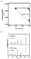
- FIG. It is a graph which shows the relationship between the ratio of Si and P, and a lattice constant. It is a graph which shows the relationship between the ratio of S and O, and a lattice constant.
- 3 is a result of CV measurement for the sulfide solid electrolyte material obtained in Example 1 and Comparative Examples 1 to 3.
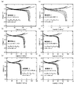
- FIG. 3 is a result of a charge / discharge test for an evaluation battery using the sulfide solid electrolyte material obtained in Example 1 and Comparative Examples 1 to 3.
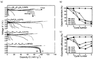
- FIG. 3 is a result of a charge / discharge test for an evaluation battery using the sulfide solid electrolyte material obtained in Example 1 and Comparative Examples 4 to 6.
- FIG. FIG. 3 is a ternary diagram illustrating sulfide solid electrolyte materials obtained in Examples 2-1 to 2-3 and Comparative Examples 2-1 and 2-2.
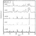
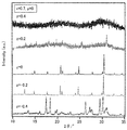
- 3 is a result of XRD measurement on the sulfide solid electrolyte materials obtained in Examples 2-1 to 2-3 and Comparative Examples 2-1 and 2-2.
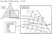
- FIG. 3 is a ternary diagram for explaining the sulfide solid electrolyte material obtained in Examples 3-1 to 3-6.
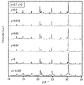
- FIG. 4 shows the results of XRD measurement for the sulfide solid electrolyte material obtained in Examples 3-1 to 3-6.
- FIG. 3 is a ternary diagram illustrating sulfide solid electrolyte materials obtained in Examples 4-1 and 4-2 and Comparative Examples 4-1 to 4-3.
- FIG. 6 shows the results of XRD measurement for the sulfide solid electrolyte materials obtained in Examples 4-1 and 4-2 and Comparative Examples 4-1 to 4-3. Evaluation batteries using the sulfide solid electrolyte materials obtained in Example 2-3, Example 3-5, Example 3-6, Example 4-2, Example 5-1, and Example 5-2 It is the result of the charging / discharging test with respect to.
- the sulfide solid electrolyte material of the present invention will be described.
- the sulfide solid electrolyte material of the present invention can be roughly divided into several embodiments. Therefore, the sulfide solid electrolyte material of the present invention will be described separately for each embodiment.
- the reason why the reduction resistance is improved is presumed to be that Si—O bonds are formed in the crystal structure by the introduced oxygen.
- the composition of Li 3.14 Si 0.34 P 0.70 S 3.32 O 0.68 is composed of tetravalent and pentavalent cations (Si and P) and anions (S and O).
- the molar ratio of anions is different. Therefore, it is estimated that a part of Li (Li that does not contribute to ion conduction) forming a skeleton structure in the crystal structure can be replaced with Si.
- the sulfide solid electrolyte material described in Patent Document 1 has a crystal structure with high Li ion conductivity.
- the crystal phase which has this crystal structure be crystal phase A '.
- the sulfide solid electrolyte material of the first embodiment has a crystal phase A similar to the crystal phase A ′.
- the crystalline phase A ′ in the sulfide solid electrolyte material described in Patent Document 1 exhibits high Li ion conductivity when Li ions are conducted through the space portion of the crystal structure. Since the crystal phase A in the sulfide solid electrolyte material of the first embodiment also has the same crystal structure as the crystal phase A ′, good Li ion conductivity is exhibited.
- the sulfide solid electrolyte material of the first embodiment preferably has the crystal phase A as the main phase.
- the crystal phase B ′ having this peak is a crystal phase having a lower Li ion conductivity than the above-described crystal phase A ′.
- the sulfide solid electrolyte material of the first embodiment may have a crystal phase B similar to the crystal phase B ′.
- the crystal phase B is considered to be within a range of ⁇ 1.00 ° with respect to the peak position of the crystal phase B ′.
- the crystal phases A and B are both crystal phases exhibiting Li ion conductivity, but the Li ion conductivity is different, and the crystal phase B has Li ion conductivity compared to the crystal phase A. It is considered low. Therefore, it is preferable to reduce the proportion of the crystal phase B.
- the sulfide solid electrolyte material of the first embodiment is usually Li (3.14-x) Si (0.34-x) P (0.70 + x) S (3.32-z) O (0.68 + z). ( ⁇ 0.13 ⁇ x ⁇ 0.13, ⁇ 0.11 ⁇ z ⁇ 0.11).
- x is usually ⁇ 0.13 or more, and may be ⁇ 0.10 or more.
- x is usually 0.13 or less and may be 0.10 or less.
- z is usually ⁇ 0.11 or more and may be ⁇ 0.07 or more.
- z is usually 0.11 or less and may be 0.07 or less.
- the sulfide solid electrolyte material of the first embodiment is usually a sulfide solid electrolyte material having crystallinity. Further, the sulfide solid electrolyte material of the first embodiment preferably has high Li ion conductivity, and the Li ion conductivity of the sulfide solid electrolyte material at 25 ° C. is 1.0 ⁇ 10 ⁇ 4 S / cm or more. It is preferable that Moreover, the shape of the sulfide solid electrolyte material of the first embodiment is not particularly limited, and examples thereof include powder. Further, the average particle diameter of the powdered sulfide solid electrolyte material is preferably in the range of 0.1 ⁇ m to 50 ⁇ m, for example.
- the sulfide solid electrolyte material of the first embodiment can be used for any application that requires Li ion conductivity. Especially, it is preferable that the sulfide solid electrolyte material of a 1st embodiment is what is used for a battery.
- the method for producing the sulfide solid electrolyte material of the first embodiment will be described in detail in “C. Method for producing sulfide solid electrolyte material” described later. Further, the sulfide solid electrolyte material of the first embodiment may have the characteristics of each embodiment described later.
- the composition of Li (4-x-4y) Si (1-x + y) P (x) S (4-2a-z) O (2a + z) is derived from the following points.
- the composition on the pseudo binary component can be expressed as Li 4-k M 1-k P k A 4 ((1-k) Li 4 MA 4 + kLi 3 PA 4 ⁇ Li 4-k M 1-k P k A 4 ).
- the composition corresponding to Li 4 MA 4 —Li 3 PA 4 is Li 4 SiS 2 O 2 —Li 3 PS 4
- system can be expressed as Li 4-x Si 1-x P x S 2 + 2x O 2-2x.
- the superionic conductor Li 10 GeP 2 S 12 type has a composition slightly deviated from the Li 4 SiS 2 O 2 —Li 3 PS 4 pseudo binary system. A sulfide solid electrolyte material having a structure is obtained.
- the deviation from the Li 4 SiS 2 O 2 —Li 3 PS 4 pseudo binary connection is shown as Li 4 ⁇ x ⁇ 4y Si 1 ⁇ x + y P x S 2 + 2x-2y O 2-2x + 2y and can be represented.
- the parameter z representing the ratio of S 2 ⁇ ⁇ O 2 ⁇ it can be expressed as Li 4 ⁇ x ⁇ 4y Si 1 ⁇ x + y P x S 2 + 2x ⁇ 2y ⁇ z O 2 ⁇ 2x + 2y + z .
- x is usually 0.65 or more and may be 0.67 or more. On the other hand, x is usually 0.75 or less and may be 0.73 or less.
- y is usually ⁇ 0.025 or more and may be ⁇ 0.03 or more. On the other hand, y is usually 0.1 or less and may be 0.08 or less.
- z is usually ⁇ 0.2 or more, and may be ⁇ 0.15 or more. On the other hand, z is usually 0 or less and may be 0.8 or less.
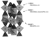
- FIG. 1 is a perspective view explaining an example of the crystal structure of the sulfide solid electrolyte material of 3rd embodiment.
- the octahedron O has Li as a central element, and has six S at the apex of the octahedron (note that a part of S may be substituted with O). ing.
- the octahedron O is, for example, a LiS 6-x O x (0 ⁇ x ⁇ 6) octahedron.
- the tetrahedron T 1 has at least one of Si and P as a central element, and has four S (note that a part of S may be replaced with O) at the apex of the tetrahedron. .
- the tetrahedron T 1 is, for example, both a SiS 4 ⁇ x O x (0 ⁇ x ⁇ 4) tetrahedron and a PS 4 ⁇ x O x (0 ⁇ x ⁇ 4) tetrahedron.
- the tetrahedron T 2 has at least one of Si and P as a central element, and has four S (note that a part of S may be replaced with O) at the apex of the tetrahedron. .
- the tetrahedron T 2 is, for example, a PS 4-x O x (0 ⁇ x ⁇ 4) tetrahedron.
- the sulfide solid electrolyte material of the third embodiment at least one of the octahedron O, the tetrahedron T 1 and the tetrahedron T 2 has a part of the S element replaced with the O element.
- the fact that part of the S element is replaced with the O element can be confirmed by, for example, analysis of an XRD pattern by the Rietveld method, neutron diffraction, or the like.
- the tetrahedron T 1 and the octahedron O share a ridge
- the tetrahedron T 2 and the octahedron O share a vertex.
- the sulfide solid electrolyte material of the third embodiment has the same composition as that of the first embodiment described above.
- the octahedron O, the tetrahedron T 1 and the tetrahedron T 2 have a predetermined crystal structure (three-dimensional structure), and the sulfide solid electrolyte material has a specific composition.
- a sulfide solid electrolyte material having good reduction resistance can be obtained.
- the sulfide solid electrolyte material of the third embodiment is not particularly limited as long as it has the above crystal structure.
- the sulfide solid electrolyte material of the third embodiment preferably contains the above crystal structure as a main component. “Containing mainly the above crystal structure” means that the ratio of the crystal structure is the largest with respect to all crystal phases contained in the sulfide solid electrolyte material.
- the proportion of the crystal structure is, for example, 50% by weight or more, preferably 70% by weight or more, and more preferably 90% by weight or more.
- the ratio of the said crystal structure can be measured by synchrotron radiation XRD, for example.
- the sulfide solid electrolyte material of the third embodiment is preferably a single-phase material having the above crystal structure.
- the sulfide solid electrolyte material of the third embodiment may have the characteristics of the first embodiment or the second embodiment described above.
- the octahedron O, the tetrahedron T 1 and the tetrahedron T 2 have a predetermined crystal structure (three-dimensional structure), and the sulfide solid electrolyte material has a specific composition.
- a sulfide solid electrolyte material having good reduction resistance can be obtained. Since the sulfide solid electrolyte material of the fourth embodiment is the same as the sulfide solid electrolyte material of the third embodiment except that the composition range is different, the description here is omitted.
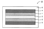
- FIG. 2 is a schematic cross-sectional view showing an example of the battery of the present invention.
- the battery 10 in FIG. 2 was formed between the positive electrode active material layer 1 containing the positive electrode active material, the negative electrode active material layer 2 containing the negative electrode active material, and the positive electrode active material layer 1 and the negative electrode active material layer 2.
- At least one of the positive electrode active material layer 1, the negative electrode active material layer 2, and the electrolyte layer 3 contains the sulfide solid electrolyte material described in the above-mentioned “A. Sulfide solid electrolyte material”.
- a battery having high reduction resistance can be obtained by using the sulfide solid electrolyte material described above.
- the battery of this invention is demonstrated for every structure.
- Negative electrode active material layer is a layer containing at least a negative electrode active material, and may contain at least one of a solid electrolyte material, a conductive material and a binder, if necessary. good.
- Examples of the negative electrode active material include a metal active material and a carbon active material.
- Examples of the metal active material include Li, In, Al, Si, and Sn.
- the metal active material may be a simple metal such as Li or an alloy such as a Li alloy.
- examples of the carbon active material include mesocarbon microbeads (MCMB), highly oriented graphite (HOPG), hard carbon, and soft carbon.
- the negative electrode active material layer contains a solid electrolyte material
- the solid electrolyte material is the sulfide solid electrolyte material described above. This is because the above-described sulfide solid electrolyte material has high reduction resistance.
- the ratio of the sulfide solid electrolyte material contained in the negative electrode active material layer varies depending on the type of battery. For example, it is in the range of 0.1% by volume to 80% by volume, and in particular, 1% by volume to 60% by volume. It is preferable to be within the range, particularly within the range of 10% by volume to 50% by volume.
- the negative electrode active material layer may further contain a conductive material.
- a conductive material By adding a conductive material, the conductivity of the negative electrode active material layer can be improved.
- the conductive material include acetylene black, ketjen black, and carbon fiber.
- the negative electrode active material layer may contain a binder. Examples of the type of binder include fluorine-containing binders such as polyvinylidene fluoride (PVDF).
- PVDF polyvinylidene fluoride
- the thickness of the negative electrode active material layer is preferably in the range of 0.1 ⁇ m to 1000 ⁇ m, for example.
- Electrolyte layer The electrolyte layer in this invention is a layer formed between a positive electrode active material layer and a negative electrode active material layer.
- the electrolyte layer is not particularly limited as long as it is a layer capable of conducting ions, but is preferably a solid electrolyte layer made of a solid electrolyte material. This is because a battery with higher safety can be obtained as compared with a battery using an electrolytic solution.
- a solid electrolyte layer contains the sulfide solid electrolyte material mentioned above.
- the ratio of the sulfide solid electrolyte material contained in the solid electrolyte layer is, for example, preferably in the range of 10% to 100% by volume, and more preferably in the range of 50% to 100% by volume.
- the thickness of the solid electrolyte layer is, for example, preferably in the range of 0.1 ⁇ m to 1000 ⁇ m, and more preferably in the range of 0.1 ⁇ m to 300 ⁇ m.
- the layer comprised from electrolyte solution may be sufficient as the electrolyte layer in this invention.
- the positive electrode active material layer in the present invention is a layer containing at least a positive electrode active material, and may contain at least one of a solid electrolyte material, a conductive material and a binder, if necessary. good.
- the positive electrode active material layer preferably contains a solid electrolyte material, and the solid electrolyte material is preferably the sulfide solid electrolyte material described above.
- the ratio of the sulfide solid electrolyte material contained in the positive electrode active material layer varies depending on the type of battery. For example, it is in the range of 0.1% by volume to 80% by volume, particularly 1% by volume to 60% by volume.
- the positive electrode active material for example, LiCoO 2 , LiMnO 2 , Li 2 NiMn 3 O 8 , LiVO 2 , LiCrO 2 , LiFePO 4 , LiCoPO 4 , LiNiO 2 , LiNi 1/3 Co 1/3 Mn 1/3 O 2 etc. can be mentioned.
- the conductive material and the binder used in the positive electrode active material layer are the same as those in the negative electrode active material layer described above.
- the thickness of the positive electrode active material layer is preferably in the range of 0.1 ⁇ m to 1000 ⁇ m, for example.
- the battery of the present invention has at least the negative electrode active material layer, the electrolyte layer, and the positive electrode active material layer described above. Furthermore, it usually has a positive electrode current collector for collecting current of the positive electrode active material layer and a negative electrode current collector for collecting current of the negative electrode active material layer.
- the material for the positive electrode current collector include SUS, aluminum, nickel, iron, titanium, and carbon.
- examples of the material for the negative electrode current collector include SUS, copper, nickel, and carbon.
- the thickness and shape of the positive electrode current collector and the negative electrode current collector are preferably appropriately selected according to the use of the battery.
- the battery case of a general battery can be used for the battery case used for this invention. Examples of the battery case include a SUS battery case.
- Battery The battery of the present invention may be a primary battery or a secondary battery, but among them, a secondary battery is preferable. This is because it can be repeatedly charged and discharged and is useful, for example, as an in-vehicle battery.
- Examples of the shape of the battery of the present invention include a coin type, a laminate type, a cylindrical type, and a square type.
- the manufacturing method of the battery of this invention will not be specifically limited if it is a method which can obtain the battery mentioned above, The method similar to the manufacturing method of a general battery can be used.
- the battery of the present invention is an all-solid battery
- a material constituting the positive electrode active material layer, a material constituting the solid electrolyte layer, and a material constituting the negative electrode active material layer are sequentially provided.
- Examples of the method include producing a power generation element by pressing, housing the power generation element inside the battery case, and caulking the battery case.
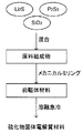
- FIG. 3 is an explanatory view showing an example of a method for producing a sulfide solid electrolyte material of the present invention.
- a raw material composition is prepared by mixing Li 2 S, P 2 S 5 , and SiO 2 .
- a mechanical milling method is performed on the raw material composition to obtain a precursor material.
- the precursor material is melted by heating and then rapidly cooled. Thereby, a sulfide solid electrolyte material is obtained.
- a sulfide solid electrolyte material having good reduction resistance can be obtained by performing the mechanical milling step and the melt quenching step.
- the manufacturing method of the sulfide solid electrolyte material of this invention is demonstrated for every process.
- the mechanical milling process in the present invention is a process for obtaining a precursor material by performing mechanical milling on the raw material composition containing the constituent components of the sulfide solid electrolyte material.
- the raw material composition is pulverized by mechanical milling to improve uniformity.
- the raw material composition in the present invention contains Li element, Si element, P element, S element and O element.
- the compound containing Li element include a sulfide of Li.
- Specific examples of the sulfide of Li include Li 2 S.
- Examples of the compound containing Si element include a sulfide of Si.
- Specific examples of the sulfide of Si include SiS 2 and the like.
- Examples of the compound containing the P element include a simple substance of P and a sulfide of P.
- Specific examples of P sulfide include P 2 S 5 .
- the compound containing S element is not particularly limited, and may be a simple substance or a sulfide.
- Examples of the sulfide include a sulfide containing the above-described element.
- the compound containing the O element is, for example, an oxide, and examples thereof include an oxide of Li, Si, or P. Specifically, mention may be made of SiO 2 or the like.
- Mechanical milling is a method of crushing a sample while applying mechanical energy.
- Examples of mechanical milling include a vibration mill, a ball mill, a turbo mill, a mechano-fusion, a disk mill, and the like. Among these, a vibration mill is preferable.
- the conditions of the vibration mill are not particularly limited as long as a desired precursor material can be obtained.
- the vibration amplitude of the vibration mill is, for example, preferably in the range of 5 mm to 15 mm, and more preferably in the range of 6 mm to 10 mm.
- the vibration frequency of the vibration mill is, for example, preferably in the range of 500 rpm to 2000 rpm, and more preferably in the range of 1000 rpm to 1800 rpm.
- the filling rate of the sample of the vibration mill is, for example, preferably in the range of 1 to 80% by volume, more preferably in the range of 5 to 60% by volume, and particularly in the range of 10 to 50% by volume.
- the processing time of the vibration mill is not particularly limited. In the vibration mill, it is preferable to use a vibrator (for example, an alumina vibrator).
- the melting and quenching step in the present invention is a step for obtaining the sulfide solid electrolyte material by melting the precursor material by heating and quenching.
- the precursor material is melted by heating.
- the heating temperature is, for example, 550 ° C. or higher, preferably 700 ° C. or higher, and more preferably 800 ° C. or higher. If the heating temperature is too low, the precursor material may not be sufficiently melted (melted). On the other hand, heating temperature is 1800 degrees C or less, for example, it is preferable that it is 1500 degrees C or less, and it is more preferable that it is 1100 degrees C or less. If the heating temperature is too high, the precursor material may react excessively with the reaction vessel (eg, quartz tube).
- the reaction vessel eg, quartz tube
- the heating time is preferably adjusted appropriately so that a desired sulfide solid electrolyte material can be obtained, and is, for example, in the range of 30 minutes to 10 hours, and preferably in the range of 1 hour to 5 hours.
- the heating of the precursor material is preferably performed in an inert gas atmosphere or in vacuum from the viewpoint of preventing oxidation.
- the molten precursor material is quenched.
- the rapid cooling method is usually a method in which a refrigerant is brought into contact with a molten precursor material.
- Contact refers to the case where the refrigerant directly contacts the molten precursor material and the case where the refrigerant indirectly contacts the molten precursor material via a reaction vessel or the like.
- coolant is not specifically limited, For example, it is 30 degrees C or less, 15 degrees C or less may be sufficient, and 0 degrees C or less may be sufficient.
- the refrigerant may be a liquid, a solid, or a gas. Specific examples of the refrigerant include water, ice, metal, air, and the like.
- Examples of the rapid cooling method include a water cooling method, an air cooling method, and a single roll method.
- the cooling rate in the rapid cooling is, for example, preferably 1 K / second or more, more preferably 10 K / second or more, and further preferably 10 2 K / second or more.
- the rapid cooling in the present invention is preferably a treatment for cooling until the temperature of the sulfide solid electrolyte material becomes 100 ° C. or less, and more preferably a treatment for cooling until the temperature becomes 50 ° C. or less.
- the sulfide solid electrolyte material obtained by the present invention is the same as the contents described in the above-mentioned “A. Sulfide solid electrolyte material”, and therefore description thereof is omitted here.
- the present invention is not limited to the above embodiment.
- the above-described embodiment is an exemplification, and the present invention has substantially the same configuration as the technical idea described in the claims of the present invention, and any device that exhibits the same function and effect is the present invention. It is included in the technical scope of the invention.
- Example 1 As starting materials, lithium sulfide (Li 2 S), diphosphorus pentasulfide (P 2 S 5 ), and silicon dioxide (SiO 2 ) were used. These powders were mixed in a glove box under an argon atmosphere at a ratio of 1.2703 g of Li 2 S, 1.3699 g of P 2 S 5 and 0.3597 g of SiO 2 to obtain a raw material composition. Next, the obtained raw material composition was pulverized for 90 minutes using a vibration mill (manufactured by CMT).
- the obtained precursor material was placed in a carbon-coated quartz tube (carbon crucible) and vacuum-sealed.
- the pressure of the vacuum sealed quartz tube was about 30 Pa.
- the quartz tube was placed in a firing furnace, heated from room temperature to 1000 ° C. over 2.5 hours, maintained at 1000 ° C. for 5 hours, and then rapidly cooled by being poured into cold water.
- FIG. 5 a ternary diagram when the anion component is only the O element is shown on the upper side of FIG. 5, and a ternary diagram when the anion component is only the S element is shown on the lower side of FIG. And the composition of Example 1 whose anion components are O element and S element can be shown between them.
- FIG. 5 a ternary diagram when the anion component is only the O element is shown on the upper side of FIG. 5
- a ternary diagram when the anion component is only the S element is shown on the lower side of FIG.
- the composition of Example 1 whose anion components are O element and S element can be shown between them.
- Li 4 SiO 4 , Li 4 SiA 4 and Li 4 SiS 4 correspond to a so-called Si-based ortho composition
- Li 3 PO 4 , Li 3 PA 4 and Li 3 PS 4 are so-called P-type.
- the composition of Example 1 is a novel composition that does not correspond to the composition on the tie line of Li 4 SiA 4 and Li 3 PA 4 .
- Comparative Examples 1 to 3 The sulfide solid electrolyte materials of Comparative Examples 1 to 3 were obtained using a method similar to the method described in Example 1 of Patent Document 1 (Japanese Patent Laid-Open No. 2013-177288).
- the composition of Comparative Example 1 is Li 3.35 Ge 0.35 P 0.65 S 4 and the composition of Comparative Example 2 is Li 3.27 Sn 0.27 P 0.73 S 4 .
- the composition was Li 3.55 Si 0.45 P 0.55 S 4 .
- the composition of Comparative Example 3 corresponds to the composition on the tie line of Li 4 SiS 4 and Li 3 PS 4 in FIG.
- composition of Comparative Example 1 corresponds to the composition on the tie line of Li 4 GeS 4 and Li 3 PS 4
- the composition of Comparative Example 2 is on the tie line of Li 4 SnS 4 and Li 3 PS 4.
- Comparative Examples 4 to 6 The sulfide solid electrolyte materials of Comparative Examples 4 to 6 were obtained using a method similar to the method described in Example 1 of Patent Document 1 (Japanese Patent Laid-Open No. 2013-177288).
- the composition of Comparative Example 4 is Li 10.35 Si 1.35 P 1.65 S 12 (Li 3.45 Si 0.45 P 0.55 S 4 )
- the composition of Comparative Example 5 is Li 10 GeP 2 S. 12 (Li 3.33 Ge 0.33 P 0.67 S 3 )
- the composition of Comparative Example 6 is Li 9.81 Sn 0.81 P 2.19 S 12 (Li 3.27 Sn 0.27 P 0.73 S 4 ).
- Example 1 the crystal phase A was obtained as a substantially single phase, and the peak of the crystal phase B having low Li ion conductivity was not confirmed.
- FIG. 7 shows the result of XRD measurement for the sulfide solid electrolyte material obtained in Example 1.
- the sulfide solid electrolyte material obtained in Example 1 could be synthesized with good reproducibility even after a plurality of experiments.
- Example 1 As shown in FIG. 11, in Example 1, the initial discharge capacity was 90 mAh / g, the Coulomb efficiency was 87%, and all values were higher than those of Comparative Examples 1 to 3.
- the molar ratio of the tetravalent and pentavalent cation to the anion is 1: 4, but in Example 1, the tetravalent and pentavalent cation (Si and P) and the anion ( The molar ratio with S and O) is 1.04: 4. It was suggested that the difference in molar ratio between cation and anion may contribute to the improvement of initial discharge capacity and coulombic efficiency.
- an evaluation battery was produced using the sulfide solid electrolyte material obtained in Example 1 and Comparative Examples 4 to 6.
- the positive electrode active material layer LiCoO 2 whose surface was coated with LiNbO 3 and a composite material of the sulfide solid electrolyte material obtained in Comparative Example 5 were used, and in the solid electrolyte layer, Example 1 and Comparative Example 4 were used.
- the sulfide solid electrolyte material obtained in (6) to (6) was used, and a Li foil was used for the negative electrode active material layer.
- a charge / discharge test was performed between 2.55 V and 4.25 V at a constant current of 0.015 mA / cm 2 to 0.019 mA / cm 2 .
- Example 1 The current value was standardized so that the C rate was equivalent to 1/20 C for each evaluation battery. The result is shown in FIG. As shown in FIG. 12A, in Example 1, a better capacity was obtained compared to Comparative Examples 4-6. Further, as shown in FIGS. 12B and 12C, in Example 1, the capacity retention ratio (FIG. 12B) and the cycle efficiency (FIG. 12C) both have values close to 100%. Indicated.
- XRD X-ray diffraction
- Example 5-1 and 5-2 A sulfide solid electrolyte material was obtained in the same manner as in Example 1 except that the ratio of the raw material contained in the raw material composition was changed so that the composition shown in Table 1 was obtained.
- a battery for evaluation was manufactured by using some sulfide solid electrolyte materials obtained in Examples as a solid electrolyte layer. Specifically, LiCoO 2 was used for the positive electrode active material layer, the sulfide solid electrolyte material obtained in the example was used for the solid electrolyte layer, and Li foil was used for the negative electrode active material layer. The result is shown in FIG. As shown in FIG. 19, in any of the examples, good reduction resistance was shown. Thus, it was confirmed that the reduction resistance was not impaired by (A) and (B).
Landscapes
- Chemical & Material Sciences (AREA)
- Engineering & Computer Science (AREA)
- Manufacturing & Machinery (AREA)
- Chemical Kinetics & Catalysis (AREA)
- Electrochemistry (AREA)
- General Chemical & Material Sciences (AREA)
- Inorganic Chemistry (AREA)
- Organic Chemistry (AREA)
- Condensed Matter Physics & Semiconductors (AREA)
- General Physics & Mathematics (AREA)
- Physics & Mathematics (AREA)
- Materials Engineering (AREA)
- Secondary Cells (AREA)
- Silicon Compounds (AREA)
- Conductive Materials (AREA)
- Battery Electrode And Active Subsutance (AREA)
Abstract
Description
まず、本発明の硫化物固体電解質材料について説明する。本発明の硫化物固体電解質材料は、幾つかの実施態様に大別することができる。そこで、本発明の硫化物固体電解質材料について、実施態様に分けて説明する。
第一実施態様の硫化物固体電解質材料は、CuKα線を用いたX線回折測定における2θ=30.26°±1.00°の位置にピークを有し、Li(3.14-x)Si(0.34-x)P(0.70+x)S(3.32-z)O(0.68+z)(-0.13≦x≦0.13、-0.11≦z≦0.11)の組成を有することを特徴とする。
第二実施態様の硫化物固体電解質材料は、CuKα線を用いたX線回折測定における2θ=30.26°±1.00°の位置にピークを有し、Li(4-x-4y)Si(1-x+y)P(x)S(4-2a-z)O(2a+z)(a=1-x+y、0.65≦x≦0.75、-0.025≦y≦0.1、-0.2≦z≦0)の組成を有することを特徴とする。
図1は、第三実施態様の硫化物固体電解質材料の結晶構造の一例を説明する斜視図である。図1に示す結晶構造において、八面体Oは、中心元素としてLiを有し、八面体の頂点に6個のS(なお、Sの一部はOで置換されていても良い)を有している。八面体Oは、例えば、LiS6-xOx(0≦x<6)八面体である。四面体T1は、中心元素としてSiおよびPの少なくとも一方を有し、四面体の頂点に4個のS(なお、Sの一部はOで置換されていても良い)を有している。四面体T1は、例えば、SiS4-xOx(0≦x<4)四面体およびPS4-xOx(0≦x<4)四面体の両方である。四面体T2は、中心元素としてSiおよびPの少なくとも一方を有し、四面体の頂点に4個のS(なお、Sの一部はOで置換されていても良い)を有している。四面体T2は、例えば、PS4-xOx(0≦x<4)四面体である。
第四実施態様の硫化物固体電解質材料は、特定の結晶構造を有し、さらに、Li(4-x-4y)Si(1-x+y)P(x)S(4-2a-z)O(2a+z)(a=1-x+y、0.65≦x≦0.75、-0.025≦y≦0.1、-0.2≦z≦0)の組成を有することを特徴とする。
図2は、本発明の電池の一例を示す概略断面図である。図2における電池10は、正極活物質を含有する正極活物質層1と、負極活物質を含有する負極活物質層2と、正極活物質層1および負極活物質層2の間に形成された電解質層3と、正極活物質層1の集電を行う正極集電体4と、負極活物質層2の集電を行う負極集電体5と、これらの部材を収納する電池ケース6とを有するものである。本発明においては、正極活物質層1、負極活物質層2および電解質層3の少なくとも一つが、上記「A.硫化物固体電解質材料」に記載した硫化物固体電解質材料を含有することを大きな特徴とする。
以下、本発明の電池について、構成ごとに説明する。
本発明における負極活物質層は、少なくとも負極活物質を含有する層であり、必要に応じて、固体電解質材料、導電化材および結着材の少なくとも一つを含有していても良い。
本発明における電解質層は、正極活物質層および負極活物質層の間に形成される層である。電解質層は、イオンの伝導を行うことができる層であれば特に限定されるものではないが、固体電解質材料から構成される固体電解質層であることが好ましい。電解液を用いる電池に比べて、安全性の高い電池を得ることができるからである。さらに、本発明においては、固体電解質層が、上述した硫化物固体電解質材料を含有することが好ましい。固体電解質層に含まれる上記硫化物固体電解質材料の割合は、例えば10体積%~100体積%の範囲内、中でも50体積%~100体積%の範囲内であることが好ましい。固体電解質層の厚さは、例えば0.1μm~1000μmの範囲内、中でも0.1μm~300μmの範囲内であることが好ましい。また、固体電解質層の形成方法としては、例えば、固体電解質材料を圧縮成形する方法等を挙げることができる。なお、本発明における電解質層は、電解液から構成される層であっても良い。
本発明における正極活物質層は、少なくとも正極活物質を含有する層であり、必要に応じて、固体電解質材料、導電化材および結着材の少なくとも一つを含有していても良い。特に、本発明においては、正極活物質層が固体電解質材料を含有し、その固体電解質材料が、上述した硫化物固体電解質材料であることが好ましい。正極活物質層に含まれる上記硫化物固体電解質材料の割合は、電池の種類によって異なるものであるが、例えば0.1体積%~80体積%の範囲内、中でも1体積%~60体積%の範囲内、特に10体積%~50体積%の範囲内であることが好ましい。また、正極活物質としては、例えばLiCoO2、LiMnO2、Li2NiMn3O8、LiVO2、LiCrO2、LiFePO4、LiCoPO4、LiNiO2、LiNi1/3Co1/3Mn1/3O2等を挙げることができる。なお、正極活物質層に用いられる導電化材および結着材については、上述した負極活物質層における場合と同様である。また、正極活物質層の厚さは、例えば0.1μm~1000μmの範囲内であることが好ましい。
本発明の電池は、上述した負極活物質層、電解質層および正極活物質層を少なくとも有するものである。さらに通常は、正極活物質層の集電を行う正極集電体、および負極活物質層の集電を行う負極集電体を有する。正極集電体の材料としては、例えばSUS、アルミニウム、ニッケル、鉄、チタンおよびカーボン等を挙げることができる。一方、負極集電体の材料としては、例えばSUS、銅、ニッケルおよびカーボン等を挙げることができる。また、正極集電体および負極集電体の厚さや形状等については、電池の用途等に応じて適宜選択することが好ましい。また、本発明に用いられる電池ケースには、一般的な電池の電池ケースを用いることができる。電池ケースとしては、例えばSUS製電池ケース等を挙げることができる。
本発明の電池は、一次電池であっても良く、二次電池であっても良いが、中でも二次電池であることが好ましい。繰り返し充放電でき、例えば車載用電池として有用だからである。本発明の電池の形状としては、例えば、コイン型、ラミネート型、円筒型および角型等を挙げることができる。また、本発明の電池の製造方法は、上述した電池を得ることができる方法であれば特に限定されるものではなく、一般的な電池の製造方法と同様の方法を用いることができる。例えば、本発明の電池が全固体電池である場合、その製造方法の一例としては、正極活物質層を構成する材料、固体電解質層を構成する材料、および負極活物質層を構成する材料を順次プレスすることにより、発電要素を作製し、この発電要素を電池ケースの内部に収納し、電池ケースをかしめる方法等を挙げることができる。
図3は、本発明の硫化物固体電解質材料の製造方法の一例を示す説明図である。図3における硫化物固体電解質材料の製造方法では、まず、Li2S、P2S5、SiO2を混合することにより、原料組成物を作製する。この際、空気中の水分によって原料組成物が劣化することを防止するために、不活性ガス雰囲気下で原料組成物を作製することが好ましい。次に、原料組成物に対してメカニカルミリング法を行い、前駆体材料を得る。次に、前駆体材料を加熱により溶融させ、その後、急冷する。これにより、硫化物固体電解質材料を得る。
以下、本発明の硫化物固体電解質材料の製造方法について、工程ごとに説明する。
本発明におけるメカニカルミリング工程は、上記硫化物固体電解質材料の構成成分を含有する原料組成物に対してメカニカルミリングを行い、前駆体材料を得る工程である。メカニカルミリングにより、原料組成物を粉砕し、均一性を向上させる。
本発明における溶融急冷工程は、上記前駆体材料を加熱により溶融させ、急冷することで、上記硫化物固体電解質材料を得る工程である。
出発原料として、硫化リチウム(Li2S)と、五硫化二リン(P2S5)と、二酸化ケイ素(SiO2)とを用いた。これらの粉末をアルゴン雰囲気下のグローブボックス内で、Li2Sを1.2703g、P2S5を1.3699g、SiO2を0.3597gの割合で混合し、原料組成物を得た。次に、得られた原料組成物を、振動ミル(シーエムティー社製)を用いて90分間粉砕した。
特許文献1(特開2013-177288号公報)の実施例1に記載された方法と同様の方法を用いて、比較例1~3の硫化物固体電解質材を得た。比較例1の組成はLi3.35Ge0.35P0.65S4であり、比較例2の組成はLi3.27Sn0.27P0.73S4であり、比較例3の組成はLi3.55Si0.45P0.55S4であった。なお、比較例3の組成は、図5におけるLi4SiS4およびLi3PS4のタイライン上の組成に該当する。また、図示しないが、比較例1の組成はLi4GeS4およびLi3PS4のタイライン上の組成に該当し、比較例2の組成はLi4SnS4およびLi3PS4のタイライン上の組成に該当する。
特許文献1(特開2013-177288号公報)の実施例1に記載された方法と同様の方法を用いて、比較例4~6の硫化物固体電解質材を得た。比較例4の組成はLi10.35Si1.35P1.65S12(Li3.45Si0.45P0.55S4)であり、比較例5の組成はLi10GeP2S12(Li3.33Ge0.33P0.67S3)であり、比較例6の組成はLi9.81Sn0.81P2.19S12(Li3.27Sn0.27P0.73S4)であった。
[X線回折測定]
実施例1および比較例1で得られた硫化物固体電解質材料に対してX線回折(XRD)測定を行った。XRD測定は粉末試料に対して、不活性雰囲気下、CuKα線使用の条件で行った。その結果を図6に示す。図6に示すように、実施例1では、2θ=12.66°、14.28°、14.81°、17.74°、20.64°、21.03°、23.96°、24.63°、27.66°、29.91°、30.26°の位置にピークが現れた。これらのピークは、Liイオン伝導性の高い結晶相Aのピークである。また、また、実施例1では、結晶相Aがほぼ単相として得られ、Liイオン伝導性の低い結晶相Bのピークは確認されなかった。一方、比較例1では、結晶相Aとほぼ一致した結晶相A´のピークが得られた。具体的には、2θ=12.36°、14.05°、14.40°、17.38°、20.18°、20.44°、23.56°、23.96°、24.93°、26.96°、29.07°、29.58°、31.71°、32.66°、33.39°の位置にピークを有する。
実施例1および比較例1~3で得られた硫化物固体電解質材料を用いて、サイクリックボルタンメトリ(CV)測定を行った。具体的には、SUS、硫化物固体電解質材料およびLiを積層したサンプル(厚さ1mm)を作製し、掃引速度1mV/secで測定した。その結果を図10に示す。図10に示すように、比較例1(Ge系)および比較例2(Sn系)では、+0V付近のピーク(Liの溶解に対応するピーク)がほとんど確認されない。また、-0V付近の還元方向の電流は、Li析出に相当するものではなく、硫化物固体電解質材料の分解に相当すると考えられる。
実施例1および比較例1~3で得られた硫化物固体電解質材料を用いて、評価用電池を作製した。正極活物質層には、LiCoO2および比較例1で得られた硫化物固体電解質材料の合材を用い、固体電解質層には、比較例1~3で得られた硫化物固体電解質材料を用い、負極活物質層には、Li箔を用いた。0.0636mA/cm2の一定電流にて、2.5V-4.2Vの間で充放電試験を行った。初期放電容量およびクーロン効率の結果を図11に示す。
原料組成物に含まれる原料の割合を、表1に示す組成が得られるように変更したこと以外は、実施例1と同様にして硫化物固体電解質材料を得た。これらの組成は、図13に示す三元系において、y=0、z=0と固定し、xを可変にした場合の組成に該当する。得られた硫化物固体電解質材料に対してX線回折(XRD)測定を行った。測定方法は、上記と同様である。その結果を図14に示す。図14に示すように、実施例2-1~2-3(x=0.65、0.7、0.75)では、実施例1と同様に、Liイオン伝導性の高い結晶相Aがほぼ単相で得られた。これに対して、比較例7-1、7-2(x=0.8、0.9)では、少なくとも主相として結晶相Aは得られなかった。これらの結果から、0.65≦x≦0.75の範囲において、結晶相Aが得られることが確認された。
原料組成物に含まれる原料の割合を、表1に示す組成が得られるように変更したこと以外は、実施例1と同様にして硫化物固体電解質材料を得た。これらの組成は、図15に示す三元系において、x=0.7、z=0と固定し、yを可変にした場合の組成に該当する。なお、実施例3-3は、実施例1と同じ組成である。得られた硫化物固体電解質材料に対してX線回折(XRD)測定を行った。測定方法は、上記と同様である。その結果を図16に示す。図16に示すように、実施例3-1~3-6(y=-0.025~0.1)では、実施例1と同様に、Liイオン伝導性の高い結晶相Aがほぼ単相で得られた。これらの結果から、-0.025≦y≦0.1の範囲において、結晶相Aが得られることが確認された。
原料組成物に含まれる原料の割合を、表1に示す組成が得られるように変更したこと以外は、実施例1と同様にして硫化物固体電解質材料を得た。これらの組成は、図17に示す三元系において、x=0.7、y=0と固定し、zを可変にした場合(図示しない方向に可変した場合)の組成に該当する。得られた硫化物固体電解質材料に対してX線回折(XRD)測定を行った。測定方法は、上記と同様である。その結果を図18に示す。図18に示すように、実施例4-1、4-2(z=-0.2~0)では、実施例1と同様に、Liイオン伝導性の高い結晶相Aがほぼ単相で得られた。これに対して、比較例8-1~8-3(x=0.4、0.2、-0.4)では、少なくとも主相として結晶相Aは得られなかった。これらの結果から、-0.2≦z≦0の範囲において、結晶相Aが得られることが確認された。
原料組成物に含まれる原料の割合を、表1に示す組成が得られるように変更したこと以外は、実施例1と同様にして硫化物固体電解質材料を得た。実施例5-1の組成は、Li(4-x-4y)Si(1-x+y)P(x)S(4-2a-z)O(2a+z)におけるx=0.65、y=0.025、z=0の組成に該当する。実施例5-2の組成は、Li(4-x-4y)Si(1-x+y)P(x)S(4-2a-z)O(2a+z)におけるx=0.75、y=0.025、z=0の組成に該当する。

2 … 負極活物質層
3 … 電解質層
4 … 正極集電体
5 … 負極集電体
6 … 電池ケース
10 … 電池
Claims (7)
- CuKα線を用いたX線回折測定における2θ=30.26°±1.00°の位置にピークを有し、
Li(4-x-4y)Si(1-x+y)P(x)S(4-2a-z)O(2a+z)(a=1-x+y、0.65≦x≦0.75、-0.025≦y≦0.1、-0.2≦z≦0)の組成を有することを特徴とする硫化物固体電解質材料。 - CuKα線を用いたX線回折測定における2θ=30.26°±1.00°の位置にピークを有し、
Li(3.14-x)Si(0.34-x)P(0.70+x)S(3.32-z)O(0.68+z)(-0.13≦x≦0.13、-0.11≦z≦0.11)の組成を有することを特徴とする硫化物固体電解質材料。 - Li元素およびS元素から構成される八面体Oと、P元素およびSi元素の少なくとも一方の元素、ならびに、S元素から構成される四面体T1と、P元素およびSi元素の少なくとも一方の元素、ならびに、S元素から構成される四面体T2とを有し、前記四面体T1および前記八面体Oは稜を共有し、前記四面体T2および前記八面体Oは頂点を共有する結晶構造を含有し、
前記八面体O、前記四面体T1および前記四面体T2の少なくとも一つは、前記S元素の一部がO元素に置換されており、
Li(4-x-4y)Si(1-x+y)P(x)S(4-2a-z)O(2a+z)(a=1-x+y、0.65≦x≦0.75、-0.025≦y≦0.1、-0.2≦z≦0)の組成を有することを特徴とする硫化物固体電解質材料。 - Li元素およびS元素から構成される八面体Oと、P元素およびSi元素の少なくとも一方の元素、ならびに、S元素から構成される四面体T1と、P元素およびSi元素の少なくとも一方の元素、ならびに、S元素から構成される四面体T2とを有し、前記四面体T1および前記八面体Oは稜を共有し、前記四面体T2および前記八面体Oは頂点を共有する結晶構造を含有し、
前記八面体O、前記四面体T1および前記四面体T2の少なくとも一つは、前記S元素の一部がO元素に置換されており、
Li(3.14-x)Si(0.34-x)P(0.70+x)S(3.32-z)O(0.68+z)(-0.13≦x≦0.13、-0.11≦z≦0.11)の組成を有することを特徴とする硫化物固体電解質材料。 - 正極活物質を含有する正極活物質層と、負極活物質を含有する負極活物質層と、前記正極活物質層および前記負極活物質層の間に形成された電解質層とを含有する電池であって、
前記正極活物質層、前記負極活物質層および前記電解質層の少なくとも一つが、請求項1から請求項4までのいずれかの請求項に記載の硫化物固体電解質材料を含有することを特徴とする電池。 - 請求項1から請求項4までのいずれかの請求項に記載の硫化物固体電解質材料の製造方法であって、
前記硫化物固体電解質材料の構成成分を含有する原料組成物に対してメカニカルミリングを行い、前駆体材料を得るメカニカルミリング工程と、
前記前駆体材料を加熱により溶融させ、急冷することで、前記硫化物固体電解質材料を得る溶融急冷工程と、
を有することを特徴とする硫化物固体電解質材料の製造方法。 - 前記溶融急冷工程における加熱温度が、800℃~1100℃の範囲内であることを特徴とする請求項6に記載の硫化物固体電解質材料の製造方法。
Priority Applications (3)
| Application Number | Priority Date | Filing Date | Title |
|---|---|---|---|
| US15/735,355 US10897059B2 (en) | 2015-07-02 | 2016-07-01 | Sulfide solid electrolyte material, battery, and producing method for sulfide solid electrolyte material |
| CN201680035622.5A CN107683510B (zh) | 2015-07-02 | 2016-07-01 | 硫化物固体电解质材料、电池和硫化物固体电解质材料的制造方法 |
| JP2017526457A JP6522125B2 (ja) | 2015-07-02 | 2016-07-01 | 硫化物固体電解質材料、電池および硫化物固体電解質材料の製造方法 |
Applications Claiming Priority (2)
| Application Number | Priority Date | Filing Date | Title |
|---|---|---|---|
| JP2015-133747 | 2015-07-02 | ||
| JP2015133747 | 2015-07-02 |
Publications (1)
| Publication Number | Publication Date |
|---|---|
| WO2017002971A1 true WO2017002971A1 (ja) | 2017-01-05 |
Family
ID=57608604
Family Applications (1)
| Application Number | Title | Priority Date | Filing Date |
|---|---|---|---|
| PCT/JP2016/069713 Ceased WO2017002971A1 (ja) | 2015-07-02 | 2016-07-01 | 硫化物固体電解質材料、電池および硫化物固体電解質材料の製造方法 |
Country Status (4)
| Country | Link |
|---|---|
| US (1) | US10897059B2 (ja) |
| JP (1) | JP6522125B2 (ja) |
| CN (1) | CN107683510B (ja) |
| WO (1) | WO2017002971A1 (ja) |
Cited By (7)
| Publication number | Priority date | Publication date | Assignee | Title |
|---|---|---|---|---|
| CN108695550A (zh) * | 2017-03-31 | 2018-10-23 | 国立大学法人东京工业大学 | 固体电解质材料及其制造方法 |
| JPWO2021145248A1 (ja) * | 2020-01-17 | 2021-07-22 | ||
| CN113365945A (zh) * | 2018-09-19 | 2021-09-07 | 蓝色电流股份有限公司 | 氧化锂硫银锗矿 |
| JP2023545343A (ja) * | 2020-12-14 | 2023-10-30 | コリア エレクトロニクス テクノロジ インスティチュート | 固体電解質およびそれを含む全固体電池 |
| WO2024014382A1 (ja) * | 2022-07-11 | 2024-01-18 | Agc株式会社 | 硫化物系固体電解質及びその製造方法、電極合剤、固体電解質層、並びに、全固体リチウムイオン二次電池 |
| US12166239B2 (en) | 2019-12-20 | 2024-12-10 | Blue Current, Inc. | Polymer microspheres as binders for composite electrolytes |
| US12191443B2 (en) | 2019-08-16 | 2025-01-07 | Blue Current, Inc. | Argyrodites doped with thiophilic metals |
Families Citing this family (4)
| Publication number | Priority date | Publication date | Assignee | Title |
|---|---|---|---|---|
| US11688879B2 (en) | 2018-03-12 | 2023-06-27 | Mitsui Mining & Smelting Co., Ltd. | Sulfide-based solid electrolyte particles |
| JP7196625B2 (ja) * | 2019-01-17 | 2022-12-27 | トヨタ自動車株式会社 | 硫化物固体電解質粒子及びその製造方法、並びに、全固体電池 |
| JP7156048B2 (ja) | 2019-01-17 | 2022-10-19 | トヨタ自動車株式会社 | 硫化物固体電解質粒子、及び、全固体電池 |
| CN112670560B (zh) * | 2020-09-04 | 2022-03-25 | 华中科技大学 | 硫化物固态电解质及其高温液相制备方法 |
Citations (4)
| Publication number | Priority date | Publication date | Assignee | Title |
|---|---|---|---|---|
| JP2007273217A (ja) * | 2006-03-31 | 2007-10-18 | Idemitsu Kosan Co Ltd | 固体電解質、その製造方法及び全固体二次電池 |
| JP2013149599A (ja) * | 2011-12-22 | 2013-08-01 | Tokyo Institute Of Technology | 硫化物固体電解質材料、電池および硫化物固体電解質材料の製造方法 |
| JP2013177288A (ja) * | 2012-02-06 | 2013-09-09 | Tokyo Institute Of Technology | 硫化物固体電解質材料、電池および硫化物固体電解質材料の製造方法 |
| JP2014135216A (ja) * | 2013-01-11 | 2014-07-24 | Toyota Motor Corp | 硫化物固体電解質材料、電池および硫化物固体電解質材料の製造方法 |
Family Cites Families (2)
| Publication number | Priority date | Publication date | Assignee | Title |
|---|---|---|---|---|
| JP5720753B2 (ja) * | 2013-10-02 | 2015-05-20 | トヨタ自動車株式会社 | 硫化物固体電解質材料、電池および硫化物固体電解質材料の製造方法 |
| JP6288716B2 (ja) | 2014-06-25 | 2018-03-07 | 国立大学法人東京工業大学 | 硫化物固体電解質材料の製造方法 |
-
2016
- 2016-07-01 US US15/735,355 patent/US10897059B2/en active Active
- 2016-07-01 CN CN201680035622.5A patent/CN107683510B/zh active Active
- 2016-07-01 WO PCT/JP2016/069713 patent/WO2017002971A1/ja not_active Ceased
- 2016-07-01 JP JP2017526457A patent/JP6522125B2/ja active Active
Patent Citations (4)
| Publication number | Priority date | Publication date | Assignee | Title |
|---|---|---|---|---|
| JP2007273217A (ja) * | 2006-03-31 | 2007-10-18 | Idemitsu Kosan Co Ltd | 固体電解質、その製造方法及び全固体二次電池 |
| JP2013149599A (ja) * | 2011-12-22 | 2013-08-01 | Tokyo Institute Of Technology | 硫化物固体電解質材料、電池および硫化物固体電解質材料の製造方法 |
| JP2013177288A (ja) * | 2012-02-06 | 2013-09-09 | Tokyo Institute Of Technology | 硫化物固体電解質材料、電池および硫化物固体電解質材料の製造方法 |
| JP2014135216A (ja) * | 2013-01-11 | 2014-07-24 | Toyota Motor Corp | 硫化物固体電解質材料、電池および硫化物固体電解質材料の製造方法 |
Cited By (13)
| Publication number | Priority date | Publication date | Assignee | Title |
|---|---|---|---|---|
| CN108695550B (zh) * | 2017-03-31 | 2021-07-16 | 国立大学法人东京工业大学 | 固体电解质材料及其制造方法 |
| CN108695550A (zh) * | 2017-03-31 | 2018-10-23 | 国立大学法人东京工业大学 | 固体电解质材料及其制造方法 |
| US12401056B2 (en) | 2018-09-19 | 2025-08-26 | Blue Current, Inc. | Lithium oxide argyrodites |
| CN113365945A (zh) * | 2018-09-19 | 2021-09-07 | 蓝色电流股份有限公司 | 氧化锂硫银锗矿 |
| US12191443B2 (en) | 2019-08-16 | 2025-01-07 | Blue Current, Inc. | Argyrodites doped with thiophilic metals |
| US12166239B2 (en) | 2019-12-20 | 2024-12-10 | Blue Current, Inc. | Polymer microspheres as binders for composite electrolytes |
| WO2021145248A1 (ja) * | 2020-01-17 | 2021-07-22 | 三菱瓦斯化学株式会社 | Snを含む硫化物系固体電解質の製造方法 |
| JP7658281B2 (ja) | 2020-01-17 | 2025-04-08 | 三菱瓦斯化学株式会社 | Snを含む硫化物系固体電解質の製造方法 |
| JPWO2021145248A1 (ja) * | 2020-01-17 | 2021-07-22 | ||
| US12525640B2 (en) | 2020-01-17 | 2026-01-13 | Mitsubishi Gas Chemical Company, Inc. | Method for producing sulfide solid electrolyte including Sn |
| JP7525724B2 (ja) | 2020-12-14 | 2024-07-30 | コリア エレクトロニクス テクノロジ インスティチュート | 固体電解質およびそれを含む全固体電池 |
| JP2023545343A (ja) * | 2020-12-14 | 2023-10-30 | コリア エレクトロニクス テクノロジ インスティチュート | 固体電解質およびそれを含む全固体電池 |
| WO2024014382A1 (ja) * | 2022-07-11 | 2024-01-18 | Agc株式会社 | 硫化物系固体電解質及びその製造方法、電極合剤、固体電解質層、並びに、全固体リチウムイオン二次電池 |
Also Published As
| Publication number | Publication date |
|---|---|
| US10897059B2 (en) | 2021-01-19 |
| CN107683510A (zh) | 2018-02-09 |
| CN107683510B (zh) | 2019-09-24 |
| US20180175447A1 (en) | 2018-06-21 |
| JPWO2017002971A1 (ja) | 2018-04-05 |
| JP6522125B2 (ja) | 2019-05-29 |
Similar Documents
| Publication | Publication Date | Title |
|---|---|---|
| JP6522125B2 (ja) | 硫化物固体電解質材料、電池および硫化物固体電解質材料の製造方法 | |
| CN105914395B (zh) | 硫化物固体电解质材料、电池和硫化物固体电解质材料的制造方法 | |
| JP6288716B2 (ja) | 硫化物固体電解質材料の製造方法 | |
| JP5521899B2 (ja) | 硫化物固体電解質材料およびリチウム固体電池 | |
| JP6044588B2 (ja) | 硫化物固体電解質材料、電池および硫化物固体電解質材料の製造方法 | |
| JP6044587B2 (ja) | 硫化物固体電解質材料、電池および硫化物固体電解質材料の製造方法 | |
| JP5516755B2 (ja) | 電極体および全固体電池 | |
| JP5975071B2 (ja) | 硫化物固体電解質材料、電池および硫化物固体電解質材料の製造方法 | |
| CN105453324B (zh) | 硫化物固体电解质材料、电池和硫化物固体电解质材料的制造方法 | |
| JP5720753B2 (ja) | 硫化物固体電解質材料、電池および硫化物固体電解質材料の製造方法 | |
| JP5561383B2 (ja) | 硫化物固体電解質材料、電池および硫化物固体電解質材料の製造方法 | |
| JP5660079B2 (ja) | 全固体電池および全固体電池の製造方法 | |
| JP2011187370A (ja) | 全固体電池 | |
| JP5895917B2 (ja) | 硫化物固体電解質材料、電池および硫化物固体電解質材料の製造方法 | |
| CN110556523B (zh) | 正极合剂、全固体电池、正极合剂的制造方法和全固体电池的制造方法 | |
| JP2015032550A (ja) | 硫化物固体電解質材料、電池および硫化物固体電解質材料の製造方法 | |
| JP5780322B2 (ja) | 硫化物固体電解質材料およびリチウム固体電池 | |
| JP2020123581A (ja) | α−リチウム固体電解質 | |
| JP6256980B2 (ja) | 硫化物固体電解質材料、電池および硫化物固体電解質材料の製造方法 | |
| JP2015032462A (ja) | 硫化物固体電解質材料 | |
| JP2016039031A (ja) | 全固体電池システム | |
| JP2017059417A (ja) | 全固体電池用イオン伝導性材料、全固体電池用イオン伝導性材料を用いた全固体電池及びそれらの製造方法 |
Legal Events
| Date | Code | Title | Description |
|---|---|---|---|
| 121 | Ep: the epo has been informed by wipo that ep was designated in this application |
Ref document number: 16818079 Country of ref document: EP Kind code of ref document: A1 |
|
| ENP | Entry into the national phase |
Ref document number: 2017526457 Country of ref document: JP Kind code of ref document: A |
|
| WWE | Wipo information: entry into national phase |
Ref document number: 15735355 Country of ref document: US |
|
| NENP | Non-entry into the national phase |
Ref country code: DE |
|
| 122 | Ep: pct application non-entry in european phase |
Ref document number: 16818079 Country of ref document: EP Kind code of ref document: A1 |