WO2017002657A1 - ディスクブレーキ - Google Patents
ディスクブレーキ Download PDFInfo
- Publication number
- WO2017002657A1 WO2017002657A1 PCT/JP2016/068320 JP2016068320W WO2017002657A1 WO 2017002657 A1 WO2017002657 A1 WO 2017002657A1 JP 2016068320 W JP2016068320 W JP 2016068320W WO 2017002657 A1 WO2017002657 A1 WO 2017002657A1
- Authority
- WO
- WIPO (PCT)
- Prior art keywords
- pad
- hole
- center
- gravity
- disk
- Prior art date
- Legal status (The legal status is an assumption and is not a legal conclusion. Google has not performed a legal analysis and makes no representation as to the accuracy of the status listed.)
- Ceased
Links
Images



Classifications
-
- F—MECHANICAL ENGINEERING; LIGHTING; HEATING; WEAPONS; BLASTING
- F16—ENGINEERING ELEMENTS AND UNITS; GENERAL MEASURES FOR PRODUCING AND MAINTAINING EFFECTIVE FUNCTIONING OF MACHINES OR INSTALLATIONS; THERMAL INSULATION IN GENERAL
- F16D—COUPLINGS FOR TRANSMITTING ROTATION; CLUTCHES; BRAKES
- F16D65/00—Parts or details
- F16D65/02—Braking members; Mounting thereof
- F16D65/04—Bands, shoes or pads; Pivots or supporting members therefor
- F16D65/092—Bands, shoes or pads; Pivots or supporting members therefor for axially-engaging brakes, e.g. disc brakes
-
- F—MECHANICAL ENGINEERING; LIGHTING; HEATING; WEAPONS; BLASTING
- F16—ENGINEERING ELEMENTS AND UNITS; GENERAL MEASURES FOR PRODUCING AND MAINTAINING EFFECTIVE FUNCTIONING OF MACHINES OR INSTALLATIONS; THERMAL INSULATION IN GENERAL
- F16D—COUPLINGS FOR TRANSMITTING ROTATION; CLUTCHES; BRAKES
- F16D55/00—Brakes with substantially-radial braking surfaces pressed together in axial direction, e.g. disc brakes
- F16D55/02—Brakes with substantially-radial braking surfaces pressed together in axial direction, e.g. disc brakes with axially-movable discs or pads pressed against axially-located rotating members
- F16D55/22—Brakes with substantially-radial braking surfaces pressed together in axial direction, e.g. disc brakes with axially-movable discs or pads pressed against axially-located rotating members by clamping an axially-located rotating disc between movable braking members, e.g. movable brake discs or brake pads
- F16D55/224—Brakes with substantially-radial braking surfaces pressed together in axial direction, e.g. disc brakes with axially-movable discs or pads pressed against axially-located rotating members by clamping an axially-located rotating disc between movable braking members, e.g. movable brake discs or brake pads with a common actuating member for the braking members
- F16D55/225—Brakes with substantially-radial braking surfaces pressed together in axial direction, e.g. disc brakes with axially-movable discs or pads pressed against axially-located rotating members by clamping an axially-located rotating disc between movable braking members, e.g. movable brake discs or brake pads with a common actuating member for the braking members the braking members being brake pads
- F16D55/226—Brakes with substantially-radial braking surfaces pressed together in axial direction, e.g. disc brakes with axially-movable discs or pads pressed against axially-located rotating members by clamping an axially-located rotating disc between movable braking members, e.g. movable brake discs or brake pads with a common actuating member for the braking members the braking members being brake pads in which the common actuating member is moved axially, e.g. floating caliper disc brakes
-
- F—MECHANICAL ENGINEERING; LIGHTING; HEATING; WEAPONS; BLASTING
- F16—ENGINEERING ELEMENTS AND UNITS; GENERAL MEASURES FOR PRODUCING AND MAINTAINING EFFECTIVE FUNCTIONING OF MACHINES OR INSTALLATIONS; THERMAL INSULATION IN GENERAL
- F16D—COUPLINGS FOR TRANSMITTING ROTATION; CLUTCHES; BRAKES
- F16D65/00—Parts or details
- F16D65/005—Components of axially engaging brakes not otherwise provided for
- F16D65/0068—Brake calipers
-
- F—MECHANICAL ENGINEERING; LIGHTING; HEATING; WEAPONS; BLASTING
- F16—ENGINEERING ELEMENTS AND UNITS; GENERAL MEASURES FOR PRODUCING AND MAINTAINING EFFECTIVE FUNCTIONING OF MACHINES OR INSTALLATIONS; THERMAL INSULATION IN GENERAL
- F16D—COUPLINGS FOR TRANSMITTING ROTATION; CLUTCHES; BRAKES
- F16D55/00—Brakes with substantially-radial braking surfaces pressed together in axial direction, e.g. disc brakes
- F16D2055/0004—Parts or details of disc brakes
- F16D2055/0016—Brake calipers
-
- F—MECHANICAL ENGINEERING; LIGHTING; HEATING; WEAPONS; BLASTING
- F16—ENGINEERING ELEMENTS AND UNITS; GENERAL MEASURES FOR PRODUCING AND MAINTAINING EFFECTIVE FUNCTIONING OF MACHINES OR INSTALLATIONS; THERMAL INSULATION IN GENERAL
- F16D—COUPLINGS FOR TRANSMITTING ROTATION; CLUTCHES; BRAKES
- F16D2121/00—Type of actuator operation force
- F16D2121/02—Fluid pressure
- F16D2121/04—Fluid pressure acting on a piston-type actuator, e.g. for liquid pressure
-
- F—MECHANICAL ENGINEERING; LIGHTING; HEATING; WEAPONS; BLASTING
- F16—ENGINEERING ELEMENTS AND UNITS; GENERAL MEASURES FOR PRODUCING AND MAINTAINING EFFECTIVE FUNCTIONING OF MACHINES OR INSTALLATIONS; THERMAL INSULATION IN GENERAL
- F16D—COUPLINGS FOR TRANSMITTING ROTATION; CLUTCHES; BRAKES
- F16D69/00—Friction linings; Attachment thereof; Selection of coacting friction substances or surfaces
- F16D69/04—Attachment of linings
- F16D69/0408—Attachment of linings specially adapted for plane linings
Definitions
- the present invention relates to a disc brake that applies braking force to a vehicle.
- a disc brake provided in a vehicle such as an automobile includes a caliper formed across the outer peripheral side of a disc that rotates together with wheels, and an inner pad that presses the disc from the inside (inner side) of the caliper (inner side friction pad) ), An outer pad (outer side friction pad) that presses the disk from the outside (outer side) of the caliper, a piston that presses the inner pad, and a claw portion that presses the outer pad (Patent Document) 1).
- Patent Document 1 a shim plate is provided between the piston and the inner pad, and a notch is provided in a portion of the shim plate that contacts the piston, thereby adjusting the surface pressure of the piston with respect to the inner pad.
- the technology to do is described.
- Patent Document 1 it is considered that the position of the center of gravity of the contact area between the inner pad and the piston (the position of the center of gravity of the contact surface) can be adjusted by adjusting the shape of the cutout of the shim plate.
- a shim plate provided with a notch is required, the cost may increase and the productivity (productivity) may be reduced.
- An object of the present invention is to provide a disc brake that can reduce costs and improve productivity.
- a disc brake includes a caliper formed across the outer peripheral side of a disc that rotates with a wheel, an inner pad and an outer pad that press the disc, and the inner pad.
- a piston that presses the outer pad, and a claw portion that presses the outer pad.
- the inner pad has a first surface that contacts the disk when the disk is pressed, and an opposite side of the first surface.
- a second surface wherein the second surface includes at least one first hole, and the outer pad is in contact with the disk when the disk is pressed; and
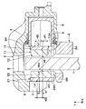
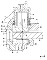
- FIG. 1 is a longitudinal sectional view showing a disc brake according to a first embodiment.
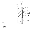
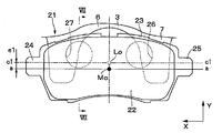
- Sectional drawing of the inner pad seen from the IV-IV direction in FIG. The side view which looked at the outer pad from the inner side (right side of FIG. 1) used as the lining side.
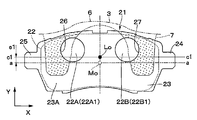
- the side view which projects and shows the 1st hole of an inner pad on an outer pad The side view which shows the inner pad by a comparative example.
- FIG. 1 to FIG. 9 show the first embodiment.
- a disk 1 rotates with wheels (not shown).
- An attachment member 2 called a carrier is located near the disk 1 and attached to a non-rotating part (not shown) of the vehicle.
- the mounting member 2 is arranged on the outer peripheral side of the disk 1 in the axial direction of the disk 1 (left and right direction in FIGS. 1, 4 and 7, the front and back directions in FIGS. 2, 3, 5, 6, 8, and 9; It is formed straddling.
- the mounting member 2 includes a pair of arm portions (not shown), a support portion 2A, and a reinforcing beam 2B.
- Each arm portion is in the direction of rotation of the disk 1 (front and back direction in FIGS. 1, 4 and 7; left and right direction in FIGS. 2, 3, 5, 6, 8 and 9;
- the disc 1 extends in the axial direction of the disc 1 so as to straddle the outer circumference of the disc 1.
- Each arm part supports the caliper 3 so as to be slidable in the disk axial direction via a sliding pin (not shown).
- each arm part of the attachment member 2 is integrally connected by the support part 2A on the inner side of the disk 1, and is integrally connected by the reinforcing beam 2B on the outer side.
- a pair of pad guides are provided on the inner side of the mounting member 2 to guide the inner pad 11 which is an inner friction pad in the disk axial direction.
- Each pad guide is formed, for example, as a groove having a U-shaped cross section (substantially U-shaped cross section) extending in the disk axial direction, and is spaced apart from one side and the other side of the disk rotation direction with the inner pad 11 interposed therebetween. Yes.
- edge part 14 and 15 of the inner pad 11 is each fitted by each pad guide via a pad spring (not shown), for example.
- a pair of pad guides are also provided on the outer side of the mounting member 2 to guide the outer pad 21 which is an outer friction pad in the disk axial direction.
- each of these pad guides is formed, for example, as a concave groove having a U-shaped cross section (substantially U-shaped cross section) extending in the disk axial direction. The side is separated from the other side.
- edge part 24,25 of the outer pad 21 is each fitted to each pad guide, for example via a pad spring (not shown).
- the caliper 3 is attached to the attachment member 2 (via a sliding pin) so as to be movable in the disk axial direction (sliding displacement).
- the caliper 3 is formed across the outer peripheral side of the disk 1 in the disk axial direction.
- the caliper 3 includes an inner leg portion 4, a bridge portion 5, and an outer leg portion 6.
- the inner leg 4 is provided on the inner side which is one side in the disk axial direction.
- the bridge portion 5 as a bridge extends from the inner leg portion 4 to the outer side which is the other side in the disc axial direction so as to straddle the outer peripheral side of the disc 1 between each arm portion of the mounting member 2.
- the outer leg portion 6 extends inwardly in the radial direction of the disc 1 (the vertical direction in FIGS. 1 to 9, referred to as the disc radial direction in the present application) from the outer side, which is the distal end side of the bridge portion 5. )
- a claw portion 7 having a bifurcated shape on the tip side.
- the inner leg portion 4 of the caliper 3 is provided with a single cylinder 8 serving as a single bore, for example.
- a piston 9 is slidably inserted into the cylinder 8.
- Brake fluid pressure is supplied into the cylinder 8 from the outside during brake operation.
- the inner leg portion 4 is integrally provided with a pair of pin mounting portions (not shown) protruding in the disc rotation direction. These pin mounting portions support the entire caliper 3 slidably on the respective arm portions of the mounting member 2 via sliding pins.
- the piston 9 is formed as a bottomed cylindrical body, and is slidably inserted into the cylinder 8 of the inner leg portion 4.
- the piston 9 has an opening end surface 9A at the tip end thereof directly abutting on the plate 13 of the inner pad 11 (without an intervening member such as a shim plate).
- the piston 9 presses the inner pad 11 toward the inner side surface (the right side surface in FIG. 1) of the disk 1 during a brake operation.
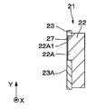
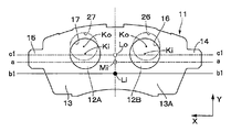
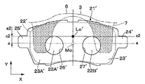
- FIGS. 2 to 9 show the inner pad 11, and FIGS. 5 to 7 show the outer pad 21.
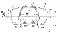
- FIG. 8 shows the through holes 26 and 27 of the outer pad 21 projected onto the inner pad 11 in the disk axial direction
- FIG. 9 projects the through holes 16 and 17 of the inner pad 11 onto the outer pad 21 in the disk axial direction.
- the inner pad 11 and the outer pad 21 have the same configuration (for example, the same material and the same, except that the positions of the through holes 16 and 17 of the inner pad 11 are different from the positions of the through holes 26 and 27 of the outer pad 21. Shape, similar thickness dimension, and similar width dimension).
- the inner pad 11 and the outer pad 21 are arranged to face both side surfaces in the axial direction of the disk 1.
- the inner pad 11 and the outer pad 21 are attached to the attachment member 2 so as to be movable in the disk axial direction.
- the inner pad 11 is pressed against the disk 1 by the piston 9, and the outer pad 21 is pressed against the disk 1 by the claw portion 7. That is, the inner pad 11 presses the disk 1 from the inner side (one side in the disk axial direction) which is the inner side of the caliper 3, and the outer pad 21 presses the outer side (the disk axial direction in the disk axial direction) of the caliper 3. Press from the other side.
- the inner pad 11 is provided with a lining 12 as a friction material that comes into frictional contact with the surface (one side surface in the axial direction) of the disk 1, and the lining 12 is provided on the opposite surface in the disk axial direction. And a plate (back plate) 13 to be formed.
- the lining 12 is fixed (joined) to a flat plate 13 extending in the disk rotation direction.
- the plate 13 is formed of, for example, metal, resin (synthetic resin), or the like, and ears 14 and 15 as protruding portions having convex shapes are separated from each other in the disk rotation direction at the side edges on both sides in the disk rotation direction. Is provided.
- edge part 14 and 15 is each slidably inserted (inserted) in the pad guide of the attachment member 2 via a pad spring.
- edge part 14 and 15 receives rotational torque (braking torque) at the time of brake operation of a vehicle. That is, each of the ear portions 14 and 15 constitutes a torque transmission portion that transmits the rotational torque received by the lining 12 from the disk 1 to the pad guide of the mounting member 2.
- the plate 13 is provided with a pair of through holes 16 and 17 spaced apart in the disk rotation direction.
- the through holes 16 and 17 are arranged symmetrically about the center of the inner pad 11 (plate 13) in the disc rotation direction (symmetrical about a line passing through the center and parallel to the Y axis).
- Each through hole 16, 17 is formed as a circular hole penetrating in the disk axial direction.
- Each through hole 16, 17 is a hole (hereinafter referred to as a gas vent hole) for venting the gas in the lining 12 when the lining 12 and the plate 13 are fixed, that is, when the lining 12 is pressed against the plate 13 and pressed. Called).
- the opening end surface 9A of the piston 9 that presses the inner pad 11 does not come into contact with the portion of the side surface 13A of the plate 13 of the inner pad 11 where the through holes 16 and 17 are formed. Contact with the part removed from. That is, the contact portion between the opening end surface 9A of the piston 9 and the plate 13 of the inner pad 11 is a portion with a dot pattern in FIG.
- the inner pad 11 includes a pair (two) of through holes 16 and 17 as a first hole provided in a surface that does not contact the disk 1 (side surface 13A of the plate 13).
- the outer pad 21 also has a lining 22 as a friction material that is in frictional contact with the surface (other side surface in the axial direction) of the disk 1, and the lining 22 is the same as the inner pad 11. And a plate (back plate) 23 provided on the opposite surface in the axial direction.
- the lining 22 is fixed (bonded) to a flat plate 23 extending in the disk rotation direction.
- the plate 23 of the outer pad 21 is formed of, for example, metal, resin (synthetic resin) or the like, and projecting portions each having a convex shape on both side edges in the disc rotation direction.
- the ears 24 and 25 are provided apart from each other in the disk rotation direction.
- edge part 24 and 25 is each slidably inserted (inserted) in the pad guide of the attachment member 2 via a pad spring.
- edge part 24 and 25 receives rotational torque (braking torque) at the time of brake operation of a vehicle. That is, each ear portion 24, 25 constitutes a torque transmission portion that transmits the rotational torque received by the lining 22 from the disk 1 to the pad guide of the mounting member 2.
- the plate 23 is provided with a pair of through holes 26 and 27 spaced apart in the disk rotation direction.
- the through holes 26 and 27 are arranged symmetrically about the center of the outer pad 21 (plate 23) in the disk rotation direction (symmetric about the line passing through the center and parallel to the Y axis).
- the through holes 26 and 27 are formed as circular holes penetrating in the disk axial direction.
- Each of the through holes 26 and 27 serves as a vent hole in the lining 22 when the lining 22 and the plate 23 are fixed, that is, when the lining 22 is pressed against the plate 23 to be pressure-bonded.
- the claw portion 7 of the caliper 3 that presses the outer pad 21 does not come in contact with the portion of the side surface 23A of the plate 23 of the outer pad 21 where the through holes 26 and 27 are formed, and comes off from the through holes 26 and 27.
- the contact portion between the claw portion 7 of the caliper 3 and the plate 13 of the inner pad 11 is a portion with a dot pattern added to FIG.
- the outer pad 21 includes a pair (two) of through holes 26 and 27 as the second hole provided in the surface that does not contact the disk 1 (side surface 23A of the plate 23).
- FIG. 8 the inner pad 11 (the plate 13) is indicated by a solid line, and the through holes 26 and 27 of the outer pad 21 when the inner pad 11 and the outer pad 21 are projected in the disk axial direction are indicated by two-dot chain lines.
- FIG. 9 shows the outer pad 21 (the plate 23 thereof) by a solid line, and shows the through holes 16 and 17 of the inner pad 11 when the outer pad 21 and the inner pad 11 are projected in the disk axial direction by a two-dot chain line. ing.
- the inner pad 11 and the inner pad 11 according to the difference between the center of gravity Ki, Ki of each through hole 16, 17 serving as the first hole and the center of gravity Ko, Ko of each through hole 26, 27 serving as the second hole.
- the barycentric position (centroid position, center position) Lo of the portion with the dot pattern can be adjusted as desired.
- contact between inner pad 11 and piston 9 is provided between inner pad 11 and piston 9, and between outer pad 21 and claw part 7, without providing intervention members, such as a shim board.
- the center of gravity position Li of the area and the center of gravity position Lo of the contact area between the outer pad 21 and the claw portion 7 can be adjusted as desired.
- the direction connecting the ears 14 and 15 provided on both sides of the inner pad 11 and the ears 24 and 25 provided on both sides of the outer pad 21 is defined as the X axis, and the in-plane and outer pads of the plate 13 of the inner pad 11 are connected.
- a direction perpendicular to the X axis in the plane of the plate 23 is defined as the Y axis.
- the axis in the disk rotation direction is the X axis
- the disk radial direction axis is the Y axis.
- the center of gravity Ki, Ki of each through-hole 16, 17 serving as the first hole is set to the Y axis with respect to the center of gravity Ko, Ko of each through-hole 26, 27 serving as the second hole. It is displaced in the direction.
- the centroids Ko and Ko of the through holes 26 and 27 serving as the second holes are more in the direction of the Y axis than the centroids Ki and Ki of the through holes 16 and 17 serving as the first holes.
- the caliper 3 is located on the bridge portion 5 side (the upper side in FIGS. 8 and 9). Thereby, the gravity center position Lo of the contact area between the outer pad 21 and the claw portion 7 and the gravity center position Li of the contact area between the inner pad 11 and the piston 9 can be brought closer in the Y-axis direction. As a result, the wear of the lining 22 of the outer pad 21 and the wear of the lining 12 of the inner pad 11 can have the same tendency.
- the disc brake according to the embodiment has the above-described configuration, and the operation thereof will be described next.
- the brake fluid pressure is supplied to the cylinder 8 of the caliper 3 to slide and displace the piston 9 toward the disk 1, thereby pressing the inner pad 11 against one side of the disk 1.
- the entire caliper 3 is slid to the inner side with respect to the arm part of the mounting member 2, and the claw part 7 of the caliper 3 moves the outer pad 21 to the disk. Press against the other side of 1.
- the inner pad 11 and the outer pad 21 can firmly hold the disk 1 rotating together with the wheel from both sides in the axial direction, and can apply a braking force to the disk 1.
- the hydraulic pressure supply to the cylinder 8 is stopped, so that the inner pad 11 and the outer pad 21 are separated from the disk 1 and return to the non-braking state again.
- the opening end surface 9A of the piston 9 is in contact with the side surface 13A of the plate 13 of the inner pad 11 at the portion marked with the dot pattern in FIG. That is, the opening end surface 9A of the piston 9 is not in contact with the portion where the through holes 16 and 17 serving as the first holes are formed, and the protruding portions 12A and 12A of the lining 12 that have entered the respective through holes 16 and 17. 12B (the end surfaces 12A1 and 12B1 thereof) are opposed to each other with a gap.
- the claw part 7 of the caliper 3 is in contact with the side surface 23A of the plate 23 of the outer pad 21 at the site with the dot pattern in FIG. That is, the claw portion 7 does not come into contact with the portion where the through holes 26 and 27 to be the second holes are formed, and the protruding portions 22A and 22B (of the lining 22 that have entered the through holes 26 and 27).
- the end faces 22A1, 22B1) face the claw portion 7 with a gap.
- the center of gravity Ki, Ki of each through hole 16, 17 and the center of gravity Ko, Ko of each through hole 26, 27 are the same as the inner pad 11 and the outer pad 21 in the disk axial direction. Are overlaid on each other (disagreement). For this reason, according to this deviation
- FIG. 10 and FIG. 11 show comparative examples.
- FIG. 10 shows an inner pad 11 ′ of a comparative example
- FIG. 11 shows an outer pad 21 ′ of a comparative example.
- the inner pad 11 ′ of the comparative example is the same as the inner pad 11 of the embodiment except that the positions of the through holes 16 ′ and 17 ′ of the plate 13 ′ are different.
- the outer pad 21 ′ of the comparative example is the same as the outer pad 21 of the embodiment except that the positions of the through holes 26 ′ and 27 ′ of the plate 23 ′ are different. Therefore, in the comparative example, the same reference numerals as those in the embodiment are given to the same components as those in the embodiment, and “′” is attached.
- the through holes 16 ′ and 17 ′ of the inner pad 11 ′ of the comparative example are bridge portions in the Y-axis direction than the through holes 16 and 17 of the inner pad 11 of the embodiment. It is located on the side opposite to the 5 side (the lower side in FIG. 10).
- the gravity center position Li ′ of the contact area between the inner pad 11 ′ and the piston 9 in the comparative example is the gravity center of the contact area between the inner pad 11 and the piston 9 in the embodiment. It is located on the bridge part 5 side (upper side in FIG. 10) in the Y-axis direction from the position Li. In this way, by adjusting the positions of the through holes 16, 17, 16 ', 17', the gravity center positions Li, Li 'can be adjusted as desired.
- the center of gravity position of the disk contact surface which is the contact surface between the linings 12, 12 'of the inner pads 11, 11' and the disk 1
- a line parallel to the X axis passing through the center of gravity position Mi is defined as a line segment a. -A.
- the barycentric position Li of the contact area according to the embodiment that is, a line parallel to the X axis passing through the barycentric Li of the contact surface of the plate 13 of the inner pad 11 and the piston 9 (open end surface 9A thereof) is a line segment b1-b1.
- the barycentric position Li ′ of the contact area according to the comparative example that is, the line parallel to the X axis passing through the barycenter Li ′ of the contact surface of the piston 9 (open end surface 9A) and the plate 13 ′ of the inner pad 11 ′ is b2. -B2.
- the inner pads 11, 11 ' when the brake is operated (during braking), the inner pads 11, 11 'receive a reaction force from the disk 1 toward the lining 12, 12' at the position of the line segment aa.
- the inner pad 11 of the embodiment receives the pressing load from the piston 9 at the position of the line segment b1-b1.
- the inner pad 11 'of the comparative example receives the pressing load from the piston 9 at the position of the line segment b2-b2.
- the distance d1 between the gravity center position Li (ie, line segment b1-b1) of the contact area according to the embodiment and the gravity center position Mi (ie, line segment aa) of the disk contact surface, and the contact area of the comparative example Comparing the distance d2 between the center of gravity position Li ′ (ie, line segment b2-b2) and the center of gravity position Mi (ie, line segment aa) of the disk contact surface, the distance d1 of the embodiment is the distance of the comparative example. It can be made smaller than d2 (d1 ⁇ d2).
- the inner pad 11 according to the embodiment can bring the reaction force from the disk 1 side and the reaction force from the piston 9 side closer to each other as the distance d1 becomes smaller.
- the direction can be uniform.
- the reaction force from the disk 1 side and the reaction force from the piston 9 side deviate by the distance d2, and for example, the Y axis direction of the lining 12'
- the bridge part 5 side the upper side in the figure
- the inner pad 11 of the embodiment can suppress uneven wear of the lining 12 as compared with the inner pad 11 ′ of the comparative example.
- the through holes 26 ′ and 27 ′ of the outer pad 21 ′ of the comparative example are more bridge members 5 in the Y-axis direction than the through holes 26 and 27 of the outer pad 21 of the embodiment. It is located on the opposite side (lower side in FIG. 11).
- the barycentric position Lo ′ of the contact area between the outer pad 21 ′ and the piston 9 in the comparative example is the barycentric position Lo of the contact area between the outer pad 21 and the piston 9 in the embodiment.
- the bridge portion 5 side upper side in FIG. 11
- the gravity center positions Lo, Lo ' can be adjusted as desired.
- a center of gravity Lo of the contact area according to the embodiment that is, a line parallel to the X axis passing through the center of gravity Lo of the contact surface of the claw portion 7 and the plate 23 of the outer pad 21 is defined as a line segment c1-c1.
- a line parallel to the X axis passing through the center of gravity Lo ′ of the contact area according to the comparative example, that is, the center of gravity Lo ′ of the contact surface of the plate 23 ′ of the claw 7 and the outer pad 21 ′ is defined as a line segment c2-c2. .
- the outer pads 21 and 21 ' when the brake is operated (braking), the outer pads 21 and 21 'receive a reaction force from the disk 1 toward the linings 22 and 22' at the position of the line aa.
- the outer pad 21 of the embodiment receives the pressing load from the claw portion 7 at the position of the line segment c1-c1.
- the outer pad 21 'of the comparative example receives the pressing load from the claw portion 7 at the position of the line segment c2-c2.
- the distance e2 between the center of gravity position Lo ′ (ie, line segment c2-c2) and the center of gravity position Mo (ie, line segment aa) of the disk contact surface the distance e1 of the embodiment is the distance of the comparative example. It can be made smaller than e2 (e1 ⁇ e2).
- the outer pad 21 of the embodiment can make the reaction force from the disk 1 side and the reaction force from the claw part 7 side close to each other as the distance e1 becomes smaller, and accordingly, wear of the lining 22 is reduced to the Y axis.
- the direction can be uniform.
- the reaction force from the disk 1 side and the reaction force from the claw part 7 side deviate by the distance e2, and for example, the Y axis direction of the lining 22'
- the bridge part 5 side the upper side in the figure
- the outer pad 21 of the embodiment can suppress uneven wear of the lining 22 as compared with the outer pad 21 'of the comparative example.
- the contact area of the inner pad 11 (FIG. 3) is adjusted by adjusting the position of the center of gravity Ki, Ki of each through hole 16, 17 and the position of the center of gravity Ko, Ko of each through hole 26, 27.
- the center of gravity position Li of the contact area of the outer pad 21 (the part with the dot pattern in FIG. 6) can be adjusted as desired.
- there is no need to provide an intervening member such as a shim plate having a notch between the inner pad 11 and the piston 9 and between the outer pad 21 and the claw portion 7.
- productivity (ease of production) can be improved.
- the first and second holes for adjusting the center-of-gravity positions Li and Lo of the contact area between the inner pad 11 and the outer pad 21 are used when the linings 12 and 22 and the plates 13 and 23 are fixed.
- the through holes 16, 17, 26, and 27 that serve as vent holes in 12 and 22 are used.
- the through holes 16, 17, 26, and 27 are originally provided in the inner pad 11 and the outer pad 21. For this reason, it is not necessary to provide the first and second holes in the inner pad 11 and the outer pad 21 again. Thereby, also from this surface, cost can be reduced and productivity can be improved.
- the center of gravity Ki, Ki of each through hole 16, 17 serving as the first hole is set in the Y-axis direction with respect to the center of gravity Ko, Ko of each through hole 26, 27 serving as the second hole.
- the configuration is shifted.
- the inner pad 11 and the piston 9 (the opening end surface 9A thereof) and the center of gravity Ki, Ki of the through-holes 16, 17 and the center of gravity Ko, Ko of the through-holes 26, 27 are displaced in the Y-axis direction.
- the center-of-gravity position Li of the contact area and the center-of-gravity position Lo of the contact area between the outer pad 21 and the claw portion 7 can be adjusted as desired in the Y-axis direction.
- the center of gravity Ko, Ko of each through-hole 26, 27 serving as the second hole is more in the direction of the Y-axis than the center of gravity Ki, Ki of each through-hole 16, 17 serving as the first hole (
- the caliper 3 is positioned on the bridge part 5 side (upper side in FIGS. 1 to 9) in the vertical direction of FIGS.
- the claw portion 7 extends in the Y-axis direction with the bridge portion 5 side as the base end side, and in a direction away from the bridge portion 5 (downward in FIGS. 1 to 9).
- the gravity center position Lo of the contact area between the outer pad 21 and the claw portion 7 is compared with the gravity center position Li of the contact area between the inner pad 11 and the piston 9 (open end surface 9A thereof) in the Y-axis direction. It tends to be biased toward the 5 side.
- the contact area between the outer pad 21 and the claw portion 7 is determined by positioning the center of gravity Ko, Ko of each through hole 26, 27 closer to the bridge portion 5 side than the center of gravity Ki, Ki of each through hole 16, 17.
- the gravity center position Lo can be adjusted in a direction away from the bridge portion 5 side. Thereby, the gravity center position Lo of the contact area between the outer pad 21 and the claw portion 7 and the gravity center position Li of the contact area between the inner pad 11 and the piston 9 (open end surface 9A thereof) are brought closer in the Y-axis direction (by extension, Can match). As a result, the wear of the lining 22 of the outer pad 21 and the wear of the lining 12 of the inner pad 11 can have the same tendency.
- FIG. 12 to FIG. 14 show a second embodiment.
- the features of the second embodiment are the center of gravity of the contact surface (contact area) of the plate of the piston and the inner pad, the center of gravity of the contact surface (contact area) of the plate of the pawl and the outer pad, and the inner pad and the outer pad.
- the center of gravity of the contact surface (contact area) between the lining and the disk is made to coincide in the Y-axis direction. Note that in the second embodiment, the same components as those in the first embodiment described above are denoted by the same reference numerals, and description thereof is omitted.
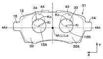
- the inner pad 31 of the second embodiment is similar to the inner pad of the first embodiment except that the positions of the through holes 33 and 34 of the plate 32 are different from the positions of the through holes 16 and 17 of the plate 13 of the first embodiment.
- the through holes 33 and 34 of the inner pad 31 are compared on the opposite side (lower side) to the bridge portion 5 with respect to the through holes 16 and 17 of the first embodiment. It is provided on the bridge part 5 side (upper side) than the through holes 16 'and 17' in the example.
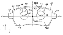
- the outer pad 41 of the second embodiment also has the outer pad 21 of the first embodiment except that the positions of the through holes 43 and 44 of the plate 42 are different from the positions of the through holes 26 and 27 of the plate 23 of the first embodiment. It is the same. Specifically, in the second embodiment, the through holes 43 and 44 of the outer pad 41 are arranged on the bridge portion 5 side with respect to the through holes 26 and 27 of the first embodiment and the through holes 26 'and 27' of the comparative example. (Upper side).
- each through-hole 33, 34 serving as the first hole (see FIG. (Center, center) Ki, Ki and the center of gravity (centroid, center) Ko, Ko of each through-hole 43, 44 to be the second hole are configured to be shifted.
- the inner pad 31 (the plate 32) is indicated by a solid line
- the through holes 43 and 44 of the outer pad 41 when the inner pad 31 and the outer pad 41 are projected in the disc axial direction are indicated by two-dot chain lines.
- FIG. 14 shows the outer pad 41 (the plate 42) by a solid line, and shows the through holes 33 and 34 of the inner pad 31 by a two-dot chain line when the outer pad 41 and the inner pad 31 are projected in the disk axial direction. ing.
- the centers of gravity Ko and Ko of the through holes 43 and 44 serving as the second holes are expressed as follows:
- the caliper 3 is positioned on the bridge part 5 side (the upper side in FIGS. 13 and 14) in the Y-axis direction with respect to the center of gravity Ki and Ki of the through holes 33 and 34 serving as the first holes.
- the position of the center of gravity (centroid position) of the contact area between the inner pad 31 and the piston 9 (open end surface 9A thereof).
- Center position Li
- centroid position center position
- Lo of the contact area between the outer pad 41 and the claw 7
- the center-of-gravity positions Mi and Mo of the disk contact surface are made to coincide with each other in the Y-axis direction.
- a line parallel to the X axis passing through the center of gravity positions Mi and Mo of the disk contact surface is defined as a line segment aa, and the center of gravity of the contact surface between the piston 9 (the opening end surface 9A) and the plate 32 of the inner pad 31 is obtained.
- a line parallel to the X axis passing through Li is defined as a line segment bb, and a line parallel to the X axis passing through the center of gravity Lo of the abutment surface of the claw portion 7 and the plate 42 of the outer pad 41 is defined as a line segment cc.
- the through holes 33 and 34 serving as the first holes are arranged such that the line segments aa, bb, and cc coincide with each other.
- the through holes 43 and 44 to be the second holes are arranged.
- the disc brake according to the second embodiment uses the inner pad 31 and the outer pad 41 as described above to match the line segments aa, bb, and cc. There is no particular difference from that according to the first embodiment.
- the through holes 33, 34, 43, and 44 are arranged so that the line segments aa, bb, and cc coincide with each other.
- the inner pad 11 includes two through holes 16 and 17 serving as first holes
- the outer pad 21 includes two through holes 26 and 27 serving as second holes.
- the inner pad may be configured to have, for example, one first hole or three or more inner pads
- the outer pad may be configured to have, for example, one second hole or three or more outer pads.
- the number of first holes and the number of second holes may be different. The same applies to the second embodiment.
- the through holes 16 and 17 serving as the first holes and the through holes 26 and 27 serving as the second holes are holes having a circular cross section.
- the present invention is not limited to this, and the first hole and the second hole may be holes having a non-circular cross section such as an oval shape, an oval shape, a rectangular shape, a C shape, a U shape, a J shape, and an oval shape. Good. The same applies to the second embodiment.
- the through holes 16 and 17 serving as the first holes are symmetric with respect to the center of the inner pad 11 in the disk rotation direction (axisymmetric with respect to a line passing through the center and parallel to the Y axis).
- positions to was mentioned as an example and demonstrated.
- the through holes 26 and 27 serving as the second holes are also symmetric with respect to the center of the outer pad 21 in the disk rotation direction (symmetric with respect to a line passing through the center and parallel to the Y axis). And explained.
- the present invention is not limited to this, and the plurality of first holes and / or the plurality of second holes may be arranged asymmetrically.
- the plurality of first holes and / or the plurality of second holes may be arranged so as to be shifted in the disk radial direction and / or the disk rotation direction across the center of the friction pad in the disk rotation direction. Furthermore, when the first hole and / or the second hole is made one, the center (center of gravity, centroid) of the one hole is changed from the center in the disk rotation direction of the friction pad to the disk radial direction and / or Or you may shift to a disc rotation direction.
- the first hole and the second hole are formed as through holes 16, 17, which serve as vent holes in the linings 12, 22 when the linings 12, 22 are fixed to the plates 13, 23.
- the case of 26 and 27 has been described as an example.
- the present invention is not limited to this, and the first hole and the second hole may be provided as holes different from the gas vent hole.
- the first hole and the second hole may be through-holes penetrating the plate, or may be bottomed concave holes (bottomed holes) having a bottom. The same applies to the second embodiment.
- the case where one piston 9 is provided on the inner leg 4 of the caliper 3 has been described as an example.
- the present invention is not limited to this, and, for example, a twin bore configuration in which two pistons are provided on the inner leg portion of the caliper, or a configuration in which three or more pistons are provided on the inner leg portion of the caliper may be employed.
- each embodiment is an exemplification, and needless to say, partial replacement or combination of the configurations shown in different embodiments is possible.
- cost can be reduced and productivity (productivity) can be improved.
- a caliper formed across the outer peripheral side of a disk that rotates with a wheel, an inner pad and an outer pad that press the disk, a piston that presses the inner pad, and a pressure that presses the outer pad
- the inner pad has a first surface that contacts the disk when the disk is pressed, and a second surface opposite to the first surface,
- the second surface includes at least one first hole
- the outer pad has a third surface that contacts the disk when the disk is pressed, and a fourth surface opposite to the third surface.
- the fourth surface includes at least one second hole, and the at least one first hole and the at least one second hole are arranged in an axial direction of the disk.
- Inner pad Wherein when projected in the outer pad, and configured to be positioned above the center of gravity of the at least one center of gravity and said at least one second hole of the first bore is deviated. Therefore, according to the deviation between the center of gravity of the first hole and the center of gravity of the second hole, the center of gravity of the contact area between the inner pad and the piston (the center of gravity of the contact surface) and the contact between the outer pad and the claw portion
- the barycentric position of the area (the barycentric position of the contact surface) can be adjusted as desired. In this case, there is no need for an interposition member such as a shim plate provided with a notch between the inner pad and the piston and between the outer pad and the claw portion, so that costs can be reduced and productivity can be improved. .
- the inner pad includes a first lining that forms the first surface, and a first plate that forms the second surface
- the outer pad includes a second lining that forms the third surface, and a second plate that forms the fourth surface, and the at least one first hole and the at least one second
- the holes are gas vent holes in the first and second linings when the first lining and the first plate and the second lining and the second plate are fixed to each other.
- the vent hole since the vent hole is originally provided in the inner pad and the outer pad, it is not necessary to provide the first and second holes in the inner pad and the outer pad. From this aspect, the cost can be reduced and the productivity can be improved.
- the direction connecting the ears that receive rotational torque provided on both sides of the inner pad and the outer pad is the X axis
- the first and second plates When the direction perpendicular to the X axis in the second and fourth planes is defined as the Y axis, the center of gravity of at least one first hole is shifted in the Y axis direction with respect to the center of gravity of at least one second hole. It is said.
- the center of gravity of the contact area between the inner pad and the piston and the center of gravity of the contact area between the outer pad and the claw portion according to the deviation in the Y-axis direction between the center of gravity of the first hole and the center of gravity of the second hole. Can be adjusted in the Y-axis direction as desired.
- the center of gravity of the at least one second hole is closer to the bridge side of the caliper than the center of gravity of the at least one first hole in the Y-axis direction. It is assumed to be positioned.
- the claw portion extends in the Y-axis direction with the bridge side as the base end side and in a direction away from the bridge. For this reason, the position of the center of gravity of the contact area between the outer pad and the claw portion tends to be biased toward the bridge side in the Y-axis direction as compared with the position of the center of gravity of the contact area between the inner pad and the piston.
- the position of the center of gravity of the contact area between the outer pad and the claw portion can be adjusted in a direction away from the bridge side. it can.
- the gravity center position of the contact area between the outer pad and the claw portion and the gravity center position of the contact area between the inner pad and the piston can be brought close to each other in the Y-axis direction (and thus matched).
- the outer pad lining wear and the inner pad lining wear can have the same tendency.
- the inner pad when the inner pad is projected onto the outer pad in the axial direction of the disk, it is parallel to the X axis passing through the center of gravity of the contact surface of the first plate with the piston.
- the at least one first hole and the at least one second hole are arranged so that they match.
Landscapes
- Engineering & Computer Science (AREA)
- General Engineering & Computer Science (AREA)
- Mechanical Engineering (AREA)
- Braking Arrangements (AREA)
Abstract
Description
Claims (5)
- ディスクブレーキであって、
車輪と共に回転するディスクの外周側を跨いで形成されるキャリパと、
前記ディスクを押圧するインナパッドおよびアウタパッドと、
前記インナパッドを押圧するピストンと、
前記アウタパッドを押圧する爪部と、
を備え、
前記インナパッドは、前記ディスクを押圧するときに該ディスクに接触する第1の面と、該第1の面と反対側の第2の面と、を有し、
前記第2の面は、少なくとも一つの第1の穴を備え、
前記アウタパッドは、前記ディスクを押圧するときに該ディスクに接触する第3の面と、該第3の面と反対側の第4の面と、を有し、
前記第4の面は、少なくとも一つの第2の穴を備え、
前記少なくとも一つの第1の穴および前記少なくとも一つの第2の穴は、前記ディスクの軸方向に前記インナパッドを前記アウタパッドに投影したとき、前記少なくとも一つの第1の穴の重心と前記少なくとも一つの第2の穴の重心がずれるように配置される
ディスクブレーキ。 - 請求項1に記載のディスクブレーキであって、
前記インナパッドは、
前記第1の面を形成する第1のライニングと、
前記第2の面を形成する第1のプレートと、
を備え、
前記アウタパッドは、
前記第3の面を形成する第2のライニングと、
前記第4の面を形成する第2のプレートと、
を備え、
前記少なくとも一つの第1の穴および前記少なくとも一つの第2の穴は、前記第1のライニングと前記第1のプレート、および、前記第2のライニングと前記第2のプレートをそれぞれ固着する際の該第1および第2のライニング内のガスを抜くための穴である
ディスクブレーキ。 - 請求項2に記載のディスクブレーキであって、
前記インナパッドおよび前記アウタパッドの両側にそれぞれ設けられる、回転トルクを受ける耳部のそれぞれを結ぶ方向をX軸、前記第1および第2のプレートの前記第2および第4の面内における前記X軸と垂直な方向をY軸と定義すると、前記少なくとも一つの第1の穴の重心は、前記少なくとも一つの第2の穴の重心に対して、前記Y軸方向にずれている
ディスクブレーキ。 - 請求項3に記載のディスクブレーキであって、
前記少なくとも一つの第2の穴の重心は、前記Y軸の方向において、前記少なくとも一つの第1の穴の重心よりも前記キャリパのブリッジ側に位置する
ディスクブレーキ。 - 請求項3に記載のディスクブレーキであって、
前記ディスクの軸方向に前記インナパッドを前記アウタパッドに投影したとき、前記第1のプレートの前記ピストンとの当接面の重心を通る前記X軸に平行な線と、前記第2のプレートの前記爪部との当接面の重心を通る前記X軸に平行な線と、前記第1および第3の面のそれぞれの重心を通る前記X軸に平行な線と、が一致するように、前記少なくとも一つの第1の穴および前記少なくとも一つの第2の穴が配置される
ディスクブレーキ。
Priority Applications (4)
| Application Number | Priority Date | Filing Date | Title |
|---|---|---|---|
| US15/740,579 US10801568B2 (en) | 2015-06-30 | 2016-06-21 | Disc brake |
| JP2017526296A JP6419966B2 (ja) | 2015-06-30 | 2016-06-21 | ディスクブレーキ |
| DE112016002994.2T DE112016002994B4 (de) | 2015-06-30 | 2016-06-21 | Scheibenbremse |
| CN201680035729.XA CN107709818B (zh) | 2015-06-30 | 2016-06-21 | 盘式制动装置 |
Applications Claiming Priority (2)
| Application Number | Priority Date | Filing Date | Title |
|---|---|---|---|
| JP2015-131325 | 2015-06-30 | ||
| JP2015131325 | 2015-06-30 |
Publications (1)
| Publication Number | Publication Date |
|---|---|
| WO2017002657A1 true WO2017002657A1 (ja) | 2017-01-05 |
Family
ID=57609308
Family Applications (1)
| Application Number | Title | Priority Date | Filing Date |
|---|---|---|---|
| PCT/JP2016/068320 Ceased WO2017002657A1 (ja) | 2015-06-30 | 2016-06-21 | ディスクブレーキ |
Country Status (5)
| Country | Link |
|---|---|
| US (1) | US10801568B2 (ja) |
| JP (1) | JP6419966B2 (ja) |
| CN (1) | CN107709818B (ja) |
| DE (1) | DE112016002994B4 (ja) |
| WO (1) | WO2017002657A1 (ja) |
Cited By (1)
| Publication number | Priority date | Publication date | Assignee | Title |
|---|---|---|---|---|
| CN114514386A (zh) * | 2019-06-05 | 2022-05-17 | 大陆特维斯股份有限公司 | 具有盘式制动器的制动活塞的定心机构 |
Families Citing this family (3)
| Publication number | Priority date | Publication date | Assignee | Title |
|---|---|---|---|---|
| CN114701468B (zh) * | 2022-03-29 | 2023-05-12 | 淄博爱科工矿机械有限公司 | 失速智能保护系统 |
| DE102022206184A1 (de) * | 2022-06-21 | 2023-12-21 | Hl Mando Corporation | Bremsklotz für ein scheibenbremssystem und scheibenbremssystem |
| CN115342055B (zh) * | 2022-08-30 | 2025-05-13 | 武汉华中数控股份有限公司 | 一种涡旋压缩机动盘底板的设计方法 |
Citations (2)
| Publication number | Priority date | Publication date | Assignee | Title |
|---|---|---|---|---|
| JPH10122277A (ja) * | 1996-10-18 | 1998-05-12 | Tokico Ltd | ディスクブレーキ |
| JP2009097600A (ja) * | 2007-10-16 | 2009-05-07 | Advics Co Ltd | ディスクブレーキの鳴き止め用シム |
Family Cites Families (17)
| Publication number | Priority date | Publication date | Assignee | Title |
|---|---|---|---|---|
| FR1289454A (fr) * | 1960-11-10 | 1962-04-06 | Dba Sa | Perfectionnements aux freins à disque |
| GB1427245A (en) | 1973-07-24 | 1976-03-10 | Girling Ltd | Disc brakes |
| US4220223A (en) * | 1978-08-01 | 1980-09-02 | Kelsey Hayes Co. | Sliding caliper disc brake friction pad assemblies |
| GB8705659D0 (en) * | 1987-03-10 | 1987-04-15 | Ferodo Ltd | Disc brake pads |
| US4887696A (en) * | 1988-11-30 | 1989-12-19 | The B. F. Goodrich Company | Disc brake |
| DE4126339C2 (de) * | 1991-08-09 | 2002-04-04 | Continental Teves Ag & Co Ohg | Schwimmsattel-Teilbelagscheibenbremse für Hochleistungsfahrzeuge |
| JPH0565929A (ja) * | 1991-09-05 | 1993-03-19 | Toyota Motor Corp | デイスクブレーキキヤリパ |
| DE19511287B4 (de) | 1994-07-21 | 2004-05-06 | Continental Teves Ag & Co. Ohg | Elektromechanische betätigbare Scheibenbremse |
| JP2002106614A (ja) * | 2000-09-28 | 2002-04-10 | Aisin Seiki Co Ltd | ディスクブレーキパッド |
| JP5454352B2 (ja) * | 2010-05-20 | 2014-03-26 | 株式会社アドヴィックス | ディスクブレーキ装置 |
| JP5894821B2 (ja) * | 2012-03-15 | 2016-03-30 | 日立オートモティブシステムズ株式会社 | ディスクブレーキ |
| DE202013012365U1 (de) | 2013-01-31 | 2016-06-22 | Continental Teves Ag & Co. Ohg | Reibbelag mit einer Stahldrahtbügelfeder |
| JPWO2014141995A1 (ja) | 2013-03-12 | 2017-02-16 | 住友ベークライト株式会社 | ブレーキパッドおよびキャリパ装置 |
| JP5751288B2 (ja) * | 2013-06-27 | 2015-07-22 | トヨタ自動車株式会社 | ディスクブレーキ装置、及び、一対のブレーキパッド |
| JP5855615B2 (ja) * | 2013-09-06 | 2016-02-09 | 日信工業株式会社 | 車両用ディスクブレーキ |
| JP6189718B2 (ja) * | 2013-11-07 | 2017-08-30 | 曙ブレーキ工業株式会社 | ディスクブレーキ用パッド及びディスクブレーキ装置 |
| ITUB20156084A1 (it) * | 2015-12-02 | 2017-06-02 | Campagnolo Srl | Pastiglia per freno a disco di bicicletta e freno a disco comprendente tale pastiglia |
-
2016
- 2016-06-21 DE DE112016002994.2T patent/DE112016002994B4/de active Active
- 2016-06-21 US US15/740,579 patent/US10801568B2/en active Active
- 2016-06-21 JP JP2017526296A patent/JP6419966B2/ja active Active
- 2016-06-21 CN CN201680035729.XA patent/CN107709818B/zh active Active
- 2016-06-21 WO PCT/JP2016/068320 patent/WO2017002657A1/ja not_active Ceased
Patent Citations (2)
| Publication number | Priority date | Publication date | Assignee | Title |
|---|---|---|---|---|
| JPH10122277A (ja) * | 1996-10-18 | 1998-05-12 | Tokico Ltd | ディスクブレーキ |
| JP2009097600A (ja) * | 2007-10-16 | 2009-05-07 | Advics Co Ltd | ディスクブレーキの鳴き止め用シム |
Cited By (1)
| Publication number | Priority date | Publication date | Assignee | Title |
|---|---|---|---|---|
| CN114514386A (zh) * | 2019-06-05 | 2022-05-17 | 大陆特维斯股份有限公司 | 具有盘式制动器的制动活塞的定心机构 |
Also Published As
| Publication number | Publication date |
|---|---|
| US10801568B2 (en) | 2020-10-13 |
| DE112016002994T5 (de) | 2018-03-15 |
| JPWO2017002657A1 (ja) | 2018-02-15 |
| DE112016002994B4 (de) | 2025-02-20 |
| JP6419966B2 (ja) | 2018-11-07 |
| CN107709818A (zh) | 2018-02-16 |
| CN107709818B (zh) | 2019-09-13 |
| US20180195568A1 (en) | 2018-07-12 |
Similar Documents
| Publication | Publication Date | Title |
|---|---|---|
| CN102852999B (zh) | 盘式制动器 | |
| US10780864B2 (en) | Disc brake | |
| JP6419966B2 (ja) | ディスクブレーキ | |
| JP2019184070A (ja) | ディスクブレーキ | |
| KR101922258B1 (ko) | 디스크 브레이크 | |
| JP2013190093A (ja) | ディスクブレーキ | |
| JPWO2020022176A1 (ja) | ディスクブレーキおよび摩擦パッド | |
| US12181008B2 (en) | Disc brake | |
| US11078976B2 (en) | Disc brake | |
| JP6745997B2 (ja) | ディスクブレーキ | |
| WO2020105611A1 (ja) | ディスクブレーキ、摩擦パッドおよびシム | |
| US20240263679A1 (en) | Disc brake and pad spring | |
| JP6253190B2 (ja) | ディスクブレーキ | |
| JP6633421B2 (ja) | ディスクブレーキ | |
| JP7192572B2 (ja) | ディスクブレーキ | |
| JP2017198262A (ja) | ディスクブレーキ | |
| JP7361653B2 (ja) | ディスクブレーキ | |
| JP2019183970A (ja) | シム、摩擦パッドおよびディスクブレーキ | |
| JP6689702B2 (ja) | ディスクブレーキ | |
| JP2015068426A (ja) | ディスクブレーキ | |
| JP2020159369A (ja) | 車両用ディスクブレーキ | |
| JP5714384B2 (ja) | ディスクブレーキ | |
| JP2013113420A (ja) | ディスクブレーキ | |
| JP2021148202A (ja) | ディスクブレーキ | |
| JP2019207000A (ja) | ディスクブレーキ |
Legal Events
| Date | Code | Title | Description |
|---|---|---|---|
| 121 | Ep: the epo has been informed by wipo that ep was designated in this application |
Ref document number: 16817765 Country of ref document: EP Kind code of ref document: A1 |
|
| ENP | Entry into the national phase |
Ref document number: 2017526296 Country of ref document: JP Kind code of ref document: A |
|
| WWE | Wipo information: entry into national phase |
Ref document number: 112016002994 Country of ref document: DE |
|
| 122 | Ep: pct application non-entry in european phase |
Ref document number: 16817765 Country of ref document: EP Kind code of ref document: A1 |
|
| WWG | Wipo information: grant in national office |
Ref document number: 112016002994 Country of ref document: DE |