WO2017002441A1 - 経路予測装置 - Google Patents
経路予測装置 Download PDFInfo
- Publication number
- WO2017002441A1 WO2017002441A1 PCT/JP2016/063161 JP2016063161W WO2017002441A1 WO 2017002441 A1 WO2017002441 A1 WO 2017002441A1 JP 2016063161 W JP2016063161 W JP 2016063161W WO 2017002441 A1 WO2017002441 A1 WO 2017002441A1
- Authority
- WO
- WIPO (PCT)
- Prior art keywords
- unit
- route
- predicted
- likelihood
- vehicle
- Prior art date
Links
- 238000004364 calculation method Methods 0.000 claims abstract description 60
- 238000001514 detection method Methods 0.000 claims abstract description 52
- 238000004458 analytical method Methods 0.000 claims abstract description 37
- 238000012545 processing Methods 0.000 claims description 48
- 230000001133 acceleration Effects 0.000 claims description 13
- 230000002093 peripheral effect Effects 0.000 abstract description 7
- 238000005259 measurement Methods 0.000 abstract 3
- 230000006870 function Effects 0.000 description 19
- 238000000034 method Methods 0.000 description 15
- 238000011156 evaluation Methods 0.000 description 10
- 230000008569 process Effects 0.000 description 7
- 238000009826 distribution Methods 0.000 description 6
- 238000005070 sampling Methods 0.000 description 6
- 238000010586 diagram Methods 0.000 description 5
- 238000005516 engineering process Methods 0.000 description 5
- 239000011159 matrix material Substances 0.000 description 4
- 230000000694 effects Effects 0.000 description 3
- 230000003287 optical effect Effects 0.000 description 3
- 230000008859 change Effects 0.000 description 2
- 238000004891 communication Methods 0.000 description 2
- 230000009471 action Effects 0.000 description 1
- 239000002131 composite material Substances 0.000 description 1
- 230000007812 deficiency Effects 0.000 description 1
- 238000013461 design Methods 0.000 description 1
- 230000005484 gravity Effects 0.000 description 1
- 230000003993 interaction Effects 0.000 description 1
- 230000001788 irregular Effects 0.000 description 1
- 239000004065 semiconductor Substances 0.000 description 1
- 230000007704 transition Effects 0.000 description 1
Images

Classifications
-
- G—PHYSICS
- G08—SIGNALLING
- G08G—TRAFFIC CONTROL SYSTEMS
- G08G1/00—Traffic control systems for road vehicles
- G08G1/16—Anti-collision systems
- G08G1/166—Anti-collision systems for active traffic, e.g. moving vehicles, pedestrians, bikes
-
- B—PERFORMING OPERATIONS; TRANSPORTING
- B60—VEHICLES IN GENERAL
- B60W—CONJOINT CONTROL OF VEHICLE SUB-UNITS OF DIFFERENT TYPE OR DIFFERENT FUNCTION; CONTROL SYSTEMS SPECIALLY ADAPTED FOR HYBRID VEHICLES; ROAD VEHICLE DRIVE CONTROL SYSTEMS FOR PURPOSES NOT RELATED TO THE CONTROL OF A PARTICULAR SUB-UNIT
- B60W30/00—Purposes of road vehicle drive control systems not related to the control of a particular sub-unit, e.g. of systems using conjoint control of vehicle sub-units
- B60W30/08—Active safety systems predicting or avoiding probable or impending collision or attempting to minimise its consequences
- B60W30/095—Predicting travel path or likelihood of collision
-
- B—PERFORMING OPERATIONS; TRANSPORTING
- B60—VEHICLES IN GENERAL
- B60W—CONJOINT CONTROL OF VEHICLE SUB-UNITS OF DIFFERENT TYPE OR DIFFERENT FUNCTION; CONTROL SYSTEMS SPECIALLY ADAPTED FOR HYBRID VEHICLES; ROAD VEHICLE DRIVE CONTROL SYSTEMS FOR PURPOSES NOT RELATED TO THE CONTROL OF A PARTICULAR SUB-UNIT
- B60W60/00—Drive control systems specially adapted for autonomous road vehicles
- B60W60/001—Planning or execution of driving tasks
- B60W60/0027—Planning or execution of driving tasks using trajectory prediction for other traffic participants
- B60W60/00276—Planning or execution of driving tasks using trajectory prediction for other traffic participants for two or more other traffic participants
-
- G—PHYSICS
- G08—SIGNALLING
- G08G—TRAFFIC CONTROL SYSTEMS
- G08G1/00—Traffic control systems for road vehicles
- G08G1/123—Traffic control systems for road vehicles indicating the position of vehicles, e.g. scheduled vehicles; Managing passenger vehicles circulating according to a fixed timetable, e.g. buses, trains, trams
- G08G1/133—Traffic control systems for road vehicles indicating the position of vehicles, e.g. scheduled vehicles; Managing passenger vehicles circulating according to a fixed timetable, e.g. buses, trains, trams within the vehicle ; Indicators inside the vehicles or at stops
-
- G—PHYSICS
- G08—SIGNALLING
- G08G—TRAFFIC CONTROL SYSTEMS
- G08G1/00—Traffic control systems for road vehicles
- G08G1/16—Anti-collision systems
-
- G—PHYSICS
- G08—SIGNALLING
- G08G—TRAFFIC CONTROL SYSTEMS
- G08G1/00—Traffic control systems for road vehicles
- G08G1/16—Anti-collision systems
- G08G1/164—Centralised systems, e.g. external to vehicles
-
- G—PHYSICS
- G08—SIGNALLING
- G08G—TRAFFIC CONTROL SYSTEMS
- G08G1/00—Traffic control systems for road vehicles
- G08G1/16—Anti-collision systems
- G08G1/167—Driving aids for lane monitoring, lane changing, e.g. blind spot detection
-
- H—ELECTRICITY
- H04—ELECTRIC COMMUNICATION TECHNIQUE
- H04W—WIRELESS COMMUNICATION NETWORKS
- H04W4/00—Services specially adapted for wireless communication networks; Facilities therefor
- H04W4/30—Services specially adapted for particular environments, situations or purposes
- H04W4/40—Services specially adapted for particular environments, situations or purposes for vehicles, e.g. vehicle-to-pedestrians [V2P]
- H04W4/44—Services specially adapted for particular environments, situations or purposes for vehicles, e.g. vehicle-to-pedestrians [V2P] for communication between vehicles and infrastructures, e.g. vehicle-to-cloud [V2C] or vehicle-to-home [V2H]
Definitions
- the present invention relates to a route predicting device for predicting a traveling route of a moving object.
- a vehicle driving support system the position of an obstacle such as a vehicle or a stop existing around the host vehicle is acquired by a sensor such as a millimeter wave radar, a laser radar, or a camera mounted on the host vehicle. Based on the relative distance and relative speed of the vehicle, a technology has been developed for controlling the host vehicle and preventing the collision after judging the collision risk.
- automatic driving technology that recognizes the surrounding environment by the sensor, automatically operates the steering wheel and brakes without the driver's operation, and reaches the destination is being developed. .
- Patent Document 1 discloses a route generation method that considers the interaction between a plurality of vehicles and a control amount evaluation method for the host vehicle.
- an optimal predicted route is calculated based on a preset control rule, there is a problem that the predicted route is erroneous when the surrounding vehicle does not follow the control rule.
- sensor errors when observing surrounding vehicle positions are not taken into account, there is a problem of erroneous prediction paths when there is an influence of sensor errors.
- there are many parameters to be set such as giving the estimated speed for each surrounding vehicle as a parameter, and there is a concern that the design is complicated.
- Patent Document 2 a plurality of predicted routes of a vehicle are generated in advance, and a route that best meets a predetermined selection criterion is selected for the generated predicted route by calculating the degree of interference of the predicted route between the vehicle and the surrounding vehicles.
- a method is disclosed.
- it is necessary to calculate the degree of interference in consideration of all the predicted routes of other surrounding vehicles with respect to the predicted route of one surrounding vehicle, and the calculation load is enormous. There is concern about becoming.
- the method for calculating only the predicted route of the host vehicle is disclosed, the method for calculating the predicted route of the surrounding vehicle is not disclosed or suggested.
- the conventional route prediction apparatus predicts the route of one neighboring vehicle by calculating the degree of interference in consideration of all the predicted routes of other neighboring vehicles with respect to the predicted route of one neighboring vehicle.
- routes of a plurality of surrounding vehicles are predicted individually.
- route prediction is performed in consideration of the mutual movement of a plurality of neighboring vehicles. Absent.
- inconsistencies such as overlapping of route predictions of a plurality of surrounding vehicles may occur, and it is a problem that the routes of the plurality of surrounding vehicles cannot be accurately predicted.
- the degree of interference is calculated in consideration of all predicted routes of other peripheral vehicles with respect to the predicted route of one peripheral vehicle, a large calculation load is also a problem.
- the present invention has been made to solve the above-described problem, and in the case where a collision may occur in a plurality of vehicles in the future, it is possible to calculate the predicted routes of the plurality of vehicles without contradiction while reducing the calculation load. Objective.
- the route prediction device is capable of colliding with the own vehicle based on an observation unit that observes the position of the own vehicle and the position and speed of the surrounding vehicle of the own vehicle, and an observation result observed by the observation unit.
- a vehicle detection unit for detecting at least two neighboring vehicles having a characteristic
- a hypothesis generation unit for generating a plurality of hypotheses for avoiding a collision of at least two neighboring vehicles detected by the vehicle detection unit
- the hypothesis generation unit A likelihood calculating unit for calculating likelihood indicating the probability of occurrence of each of the plurality of hypotheses generated in step (b), and a predicted route of the at least two neighboring vehicles based on the likelihood calculated by the likelihood calculating unit.
- a predicted path analysis unit that outputs the analysis result.
- the figure which shows the structure of the route prediction apparatus 100 which concerns on Embodiment 1 of this invention The figure which shows the hardware structural example of the path
- route prediction apparatus 100 which concerns on Embodiment 1 of this invention The flowchart which shows the process in the route estimation apparatus 100 which concerns on Embodiment 1 of this invention.
- Embodiment 1 FIG. Embodiments of the present invention will be described below.
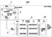
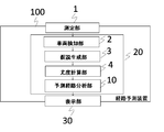
- FIG. 1 is a configuration diagram illustrating a route prediction apparatus 100 according to the first embodiment.
- the route prediction device 100 includes an observation unit 1, a vehicle detection unit 2, a hypothesis generation unit 3, a likelihood calculation unit 4, and a predicted route analysis unit 10.
- the observation unit 1 uses a sensor such as a millimeter wave radar, a laser radar, an optical camera, an infrared camera, and a communication device that receives GPS positions of surrounding vehicles and pedestrians, and the like, Measure the position and speed of vehicles and pedestrians.
- the vehicle detection unit 2 has a function of detecting the own vehicle and at least two neighboring vehicles having a possibility of collision based on the observation result observed by the observation unit 1, and includes a lane detection unit 5, a tracking processing unit 6, a collision A detection unit 7 is provided.
- the hypothesis generation unit 3 has a function of generating a plurality of hypotheses for avoiding a collision between two surrounding vehicles detected by the vehicle detection unit 2.
- the likelihood calculation unit 4 has a function of calculating a likelihood indicating the probability of occurrence for each hypothesis generated by the hypothesis generation unit 3.
- the route prediction unit 8 and the hypothesis likelihood calculation unit 9 are I have.
- the predicted route analysis unit 10 has a function of analyzing a suitable predicted route based on the likelihood calculated by the likelihood calculating unit 4.
- Each function of the hypothesis likelihood calculation unit 9 and the predicted path analysis unit 10 is realized by a processing circuit (Processing Circuit). Even if the processing circuit is dedicated hardware, a CPU that executes a program stored in a memory (Central Processing Unit, central processing unit, processing unit, arithmetic unit, microprocessor, microcomputer, processor, DSP) It may be.
- a processing circuit Central Processing Unit, central processing unit, processing unit, arithmetic unit, microprocessor, microcomputer, processor, DSP
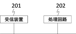
- the path prediction device 100 includes a receiving device 201 including the observation unit 1 and a processing circuit 202, as shown in FIG.
- the processing circuit 202 may be, for example, a single circuit (a single circuit), a composite circuit (multi circuit), a programmed processor (a programmed processor), a parallel programmed processor (ASICCipSicCipSicCerciseCipSicCipSicCeCipSicCeCipSicCeCipSicCeCipSicCipSicCipSicCipSicCiP, and so on). ), FPGA (Field Programmable Gate Array), or a combination thereof.
- Observation unit 1 vehicle detection unit 2, hypothesis generation unit 3, likelihood calculation unit 4, lane detection unit 5, tracking processing unit 6, collision detection unit 7, route prediction unit 8, hypothesis likelihood calculation unit 9, prediction route analysis
- the functions of the respective units of the unit 10 may be realized by a processing circuit, or the functions of the respective units may be collectively realized by a processing circuit.
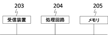
- the path prediction device 100 includes a receiving device 203, a processing circuit 204, and a memory 205 as shown in FIG.
- Observation unit 1 vehicle detection unit 2, hypothesis generation unit 3, likelihood calculation unit 4, lane detection unit 5, tracking processing unit 6, collision detection unit 7, route prediction unit 8, hypothesis likelihood calculation unit 9, prediction route analysis
- the function of the unit 10 is realized by software, firmware, or a combination of software and firmware.
- Software and firmware are described as programs and stored in a memory.
- the processing circuit 204 implements the functions of each unit by reading and executing a program stored in the memory. An example of these programs can be represented by steps S101 to S108 shown in FIG.
- the memory 205 is, for example, a nonvolatile or volatile semiconductor memory such as RAM, ROM, flash memory, EPROM, EEPROM, a magnetic disk, a flexible disk, an optical disk, a compact disk, a mini disk, a DVD, or the like. Applicable.
- observation unit 1 vehicle detection unit 2, hypothesis generation unit 3, likelihood calculation unit 4, lane detection unit 5, tracking processing unit 6, collision detection unit 7, route prediction unit 8, hypothesis likelihood calculation unit 9, prediction
- a part of the functions of the route analysis unit 10 may be realized by dedicated hardware, and part of the functions may be realized by software or firmware.
- the function of the observation unit 1 is realized by a processing circuit as dedicated hardware, and the vehicle detection unit 2, hypothesis generation unit 3, likelihood calculation unit 4, lane detection unit 5, tracking processing unit 6, collision detection
- the functions of the unit 7, the route prediction unit 8, the hypothesis likelihood calculation unit 9, and the prediction route analysis unit 10 can be realized by the processing circuit reading and executing the program stored in the memory.
- the processing circuit can realize the above functions by hardware, software, firmware, or a combination thereof.
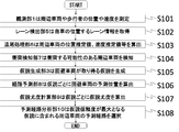
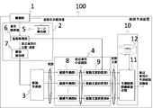
- FIG. 4 is a flowchart showing processing in the route prediction apparatus 100 according to Embodiment 1 of the present invention.
- the observation unit 1 in the route prediction device 100 uses sensors such as millimeter wave radar, laser radar, optical camera, infrared camera, and a communication device that receives GPS positions of surrounding vehicles and pedestrians.
- the area including the own vehicle and other moving vehicles is observed, and the positions and speeds of surrounding vehicles and pedestrians are measured (S101).
- the lane detection unit 5 in the vehicle detection unit 2 recognizes a white line from a camera image or the like, and obtains lane information where the vehicle is located (S102).
- the tracking processing unit 6 in the vehicle detection unit 2 calculates a position estimation value of the surrounding vehicle, a speed estimation value, and an estimation error covariance matrix of the position and speed through tracking processing based on the position and speed acquired by the sensor. (S103).
- the collision detection unit 7 in the vehicle detection unit 2 detects surrounding vehicles that may collide with each other (S104). For example, it may be detected based on the concept of TTC (Time To Collision). TTC is defined by equation (1). If TTC is equal to or less than a threshold, it is detected as a vehicle that may collide. Here, the vehicle i is traveling on the same lane as the vehicle j, and the vehicle i is a preceding vehicle of the surrounding vehicle j.
- TTC Time To Collision
- a predetermined area may be set around the own vehicle, and a vehicle having a predicted position after 1 to N steps in the area may be detected and regarded as a target vehicle.
- N predicted positions up to N steps ahead are calculated as in equation (2).
- Equations (2) to (5) are prediction equations based on a motion model (hereinafter, a constant velocity motion model) in which the vehicle travels with the current speed being constant.
- a constant velocity motion model in which the vehicle travels with the current speed being constant.
- a constant acceleration motion model may be predicted depending on the traveling state.
- the hypothesis generation unit 3 performs the following process when a plurality of collision possibilities are detected by the collision detection unit 7 and at least two surrounding vehicles having a collision possibility are detected.
- the hypothesis generation unit 3 first selects at least two neighboring vehicles (hereinafter referred to as avoiding vehicles) that have a collision possibility to take an avoidance action in order to avoid the plurality of collision possibilities.
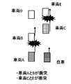
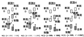
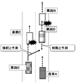
- a prediction scene (hereinafter referred to as a hypothesis) is generated from a combination of collision avoidance models that can be taken by at least two avoiding vehicles (S105). For example, as shown in FIG. 5, when the own vehicle and vehicles A to E exist and vehicles A and B and vehicles C and E collide, in order to avoid the collision between the following vehicles A and C, Avoid according to the collision avoidance model.
- a braking avoidance model may be defined as the collision avoidance model.
- the braking avoidance model is a model that avoids collision by braking while maintaining the lane
- the left / right steering avoidance model is a model that changes lane to the left / right by inputting the steering amount and avoids collision.
- the braking amount or the steering amount is set so as not to exceed a predetermined limit value.
- FIG. 5 since the traveling lane has two lanes, four hypotheses are generated from the combination of the collision avoidance models of the vehicles A and C as shown in FIG. In FIG.
- a combination of models that the vehicles A and C can take can be treated as a predicted scene (hypothesis).
- This hypothesis is stored in advance in a memory or the like, and a hypothesis suitable for the arrangement pattern of the avoiding vehicle can be read from the memory to extract the hypothesis.
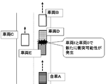
- the conventional technology does not describe an example of generating a combination of avoidance models of at least two neighboring vehicles with a possibility of collision, and calculates the degree of interference with other neighboring vehicles individually for each neighboring vehicle. For this reason, it is necessary to calculate the degree of interference even in a state where contradictions occur, such as routes of a plurality of surrounding vehicles overlapping each other.
- the present embodiment by using a combination of avoidance models of at least two neighboring vehicles, it is possible to generate a hypothesis focused on only a combination of routes that at least two neighboring vehicles can take. As a result, it is possible to reduce the amount of calculation processing by advancing the calculation processing by focusing on a combination of necessary routes without causing a contradiction such as overlapping of routes that at least two neighboring vehicles can take.
- the route prediction unit 8 in the likelihood calculation unit 4 calculates a predicted position up to N steps ahead based on the collision avoidance model for the avoidance vehicle for each hypothesis shown in FIG. 6 as a future predicted position (S106).
- the predicted position up to N steps ahead is calculated as a future predicted position on the assumption that the vehicle moves at a constant speed.
- a predicted position calculation method based on a collision avoidance model will be described.
- a temporary path (predicted position up to N steps ahead) is calculated as shown in Equation (6). : Braking acceleration
- the predicted position of the vehicle with respect to steering differs depending on vehicle parameters such as the vehicle weight, the position of the center of gravity of the vehicle body, and the yaw moment of inertia
- the predicted position is calculated in advance.
- a parameter estimated by a known learning algorithm or the like may be used.
- the hypothesis likelihood calculation unit 9 in the likelihood calculation unit 4 calculates the hypothesis likelihood based on the temporary route calculated by the route prediction unit 8 for each hypothesis (S107). For example, regarding the calculation of hypothesis likelihood, likelihood evaluation is performed using the collision time.
- the number of predicted steps n min (i, j) that vehicles i and j are closest to is defined by equation (9), and the distance R min (i, j) between vehicles i and j is defined by equation (10).
- the vehicles i and j are considered to collide and the collision time is calculated.
- the collision time is set as a fixed value equal to or greater than the maximum prediction step number N.
- Equation (13) The left side of Equation (13) is the likelihood of the mth hypothesis ⁇ m, and Z (k) means the sensor observation value at the latest sample time k. Equation (13) means that the sum of collision times is taken for all combinations of surrounding vehicles. However, the above combination may be limited to only the two closest vehicles, or may be limited to only vehicles that are predicted to be on the same lane.
- the likelihood evaluation may be performed in consideration of the sensor error or the error after the tracking process.
- the collision risk is calculated based on the position estimation error covariance matrix output from the tracking processing unit 6 and the position and speed estimation values.
- Equation (17) The number of predicted steps n min (i, j) that minimizes the Mahalanobis square distance between vehicles i and j is given by Equation (17), and the Mahalanobis square distance minimum value ⁇ min (i, j) between vehicles i and j is given by Equation (18). ).
- Equation (19) The right side of equation (19) means that the sum of Mahalanobis square distances is taken for all combinations of vehicles. However, it may be limited only to the two closest vehicles, or may be limited to only vehicles that are predicted to be on the same lane.
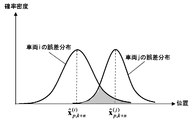
- the reciprocal of the degree of overlap may be used for the prediction error covariance matrix of the n steps ahead, using the overlap between prediction error distributions between vehicles as an index.
- the probability distribution of vehicles i and j is represented with the horizontal axis representing the position and the vertical axis representing the probability density function based on the error distribution.
- the degree of overlap corresponds to a range where the vehicle error distributions in FIG. 7 overlap (the hatched portion in FIG. 7). 7 is an area because the position is one-dimensional for convenience of explanation, but it is a volume on a two-dimensional plane.
- the likelihood evaluation value may be defined by equation (20).
- the hypothesis likelihood of each hypothesis is output.
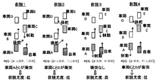
- FIG. 8 is a diagram for explaining an output example by hypothesis likelihood calculation. From FIG. 8, Hypothesis 1 has collision with vehicles A and C, Hypothesis 2 has collision with vehicles C and D, Hypothesis 4 has low likelihood because vehicle C and D collide, and Hypothesis 3 has no collision. A result with a high hypothesis likelihood is obtained.
- the predicted path analysis unit 10 first calculates the hypothesis reliability from the equation (21). As a result, the reliability of the predicted path corresponding to each hypothesis can be grasped.
- the predicted route analysis unit 10 can output the analysis result related to the predicted route in various formats using the reliability of the predicted route. For example, the predicted route with the maximum reliability can be selectively output by selecting the predicted route of the surrounding vehicle included in the hypothesis ⁇ m having the maximum hypothesis reliability (S108). Moreover, it is also possible to output other formats from the predicted path analysis unit 10 using the reliability information.
- the hypothetical reliability of hypothesis 3 is the highest in the example of FIG. 8, so that vehicle A selects the predicted route based on braking avoidance and vehicle C selects the predicted route based on braking avoidance. .
- the route prediction apparatus 100 is based on the observation unit 1 that observes the position and speed of the vehicle and its surrounding vehicles, and the observation results observed by the observation unit 1.
- a vehicle detection unit 2 that detects the host vehicle and at least two neighboring vehicles that may collide, and a hypothesis generation unit 3 that generates a plurality of hypotheses that avoid collision between at least two neighboring vehicles detected by the vehicle detection unit 2
- a likelihood calculation unit 4 that calculates the likelihood indicating the probability of occurrence of each of the plurality of hypotheses generated by the hypothesis generation unit 3 and at least 2 based on the likelihood calculated by the likelihood calculation unit 4
- a route prediction apparatus comprising: a predicted route analysis unit that analyzes predicted routes of two neighboring vehicles and outputs the analysis result.
- the vehicle detection unit 2 includes the lane detection unit 5 that detects the lane where the vehicle is located based on the observation result observed by the observation unit 1, and the observation that is observed by the observation unit 1.
- a tracking processing unit 6 that tracks the surrounding vehicle of the own vehicle based on the result, and a collision detection unit 7 that detects at least two surrounding vehicles that may collide from the surrounding vehicles that are tracked by the tracking processing unit 6; , Provided. With such a configuration, it is possible to detect at least two surrounding vehicles having a possibility of collision.
- the likelihood calculating unit 4 predicts the future positions of at least two neighboring vehicles for each hypothesis generated by the hypothesis generating unit 3, and the route predicting unit 8
- a hypothesis likelihood calculation unit 9 that calculates likelihoods indicating the likelihood of occurrence of each of a plurality of hypotheses generated by the hypothesis generation unit 3 based on the future positions of the at least two neighboring vehicles predicted in It is provided with.
- the predicted route analysis unit 10 selects and outputs the predicted routes of the at least two vehicles based on the likelihood calculated by the hypothesis likelihood calculation unit 9. .
- a predicted route that is most likely to occur can be expressed as a prediction result of the route prediction device 100.
- Embodiment 2 the format for selectively outputting the predicted route with the maximum reliability from the predicted route analysis unit 10 is disclosed, but it is also possible to output the analysis result in other formats.
- the second embodiment a case where an analysis result different from that in the first embodiment is output will be described.
- FIG. 9 is a configuration diagram showing the route prediction apparatus 100 according to the second embodiment.
- the route prediction apparatus 100 of the present embodiment includes an observation unit 1, a lane detection unit 5, a tracking processing unit 6, a collision detection unit 7, a hypothesis generation unit 3, a route prediction unit 8, and a hypothesis likelihood calculation. 9, a predicted path analysis unit 10, and a predicted path reliability calculation unit 11 included in the predicted path analysis unit 10.
- the hardware configuration for realizing the functions of the respective units in the route prediction apparatus 100 shown in FIG. 9 is represented by the configuration of FIG. 2 or FIG. 3 as in the first embodiment.
- the predicted route reliability calculation unit 11 calculates an index representing the likelihood of occurrence of the predicted route of each vehicle as the predicted route reliability.
- the reliability with which the vehicle i adopts the predicted route based on the collision avoidance model j is calculated by Expression (22).
- the left side of Equation (22) is the reliability with which the vehicle i adopts a predicted route based on the collision avoidance model j.
- ⁇ m ) in the equation (23) is a term relating to the combination, and is 1 when the predicted path is included in the hypothesis ⁇ m and 0 when not included.
- a value obtained by normalizing the predicted path based on the collision avoidance model j for the vehicle i with the reliability of the all collision avoidance model may be replaced with the predicted path reliability. Since other processes are the same as those in the first embodiment, description thereof is omitted.
- the predicted route analysis unit 10 is based on the likelihood calculated by the likelihood calculating unit 4, and the predicted route reliability indicating the likelihood of the predicted routes of at least two neighboring vehicles.
- the predicted route reliability calculation unit 11 is provided for calculating the predicted route for each predicted route.
- Embodiment 3 shows a configuration in the case where the output from the route prediction apparatus 100 according to the first and second embodiments is displayed on the display unit.
- FIG. 10 is a configuration diagram illustrating the route prediction apparatus 100 according to the third embodiment.
- the route prediction apparatus 100 according to the third embodiment includes an observation unit 1, a signal processing unit 20, and a display unit 30, and the signal processing unit 20 is the vehicle shown in the first and second embodiments.
- a detection unit 2, a hypothesis generation unit 3, a likelihood calculation unit 4, and a predicted path analysis unit 10 are included.
- the hardware configuration for realizing the function of each unit in the route prediction apparatus 100 shown in FIG. 10 is represented by the configuration of FIG. 2 or FIG. 3 as in the first embodiment.
- the observation unit 1 observes an area including the own vehicle and other moving vehicles as in the first and second embodiments, and the observation results are used in the first and second embodiments.
- the signal processing unit 20 generates a plurality of hypotheses indicating models in which at least two neighboring vehicles having a possibility of collision avoid the collision, and sets the predicted route reliability of the predicted route corresponding to each of the plurality of hypotheses.
- the display unit 30 displays a predicted route that can be taken by at least two neighboring vehicles and a reliability corresponding to the predicted route on the display screen.
- the position of the own vehicle, the observation unit 1 that observes the position and speed of the surrounding vehicle of the own vehicle, and the observation result observed by the observation unit 1 are detected.
- a signal for generating a plurality of hypotheses indicating a collision avoidance model of at least two neighboring vehicles having a possibility of collision, and calculating a predicted route reliability of the predicted route of the at least two neighboring vehicles corresponding to each of the plurality of hypotheses A processing unit 20 and a display unit 30 for displaying the predicted route reliability and the predicted route reliability of the at least two neighboring vehicles based on the predicted route reliability calculated by the signal processing unit 20 are provided. .
- the route prediction device 100 can visually grasp the predicted routes of the surrounding vehicles. Further, by displaying the predicted route by changing the color according to the predicted route reliability, the user can more accurately recognize the predicted route having the higher predicted route reliability.
- Embodiment 4 FIG.
- the analysis result of the predicted path is output independently at each time, but it is also possible to analyze the predicted path in consideration of continuity in the time direction.
- the fourth embodiment a case where an analysis result different from those in the first and second embodiments is output will be described.
- FIG. 13 is a configuration diagram illustrating the route prediction apparatus 100 according to the fourth embodiment.
- the route prediction device 100 includes an observation unit 1, a lane detection unit 5, a tracking processing unit 6, a collision detection unit 7, a hypothesis generation unit 3, a route prediction unit 8, and a hypothesis likelihood calculation. 9, a predicted route analysis unit 10, a predicted route reliability calculation unit 11 and a reliability memory 12 provided in the predicted route analysis unit 10.
- the hardware configuration for realizing the functions of the respective units in the route prediction apparatus 100 shown in FIG. 13 is represented by the configuration of FIG.
- the hypothesis likelihood calculation unit 9 in the likelihood calculation unit 4 calculates the hypothesis likelihood based on the temporary route calculated by the route prediction unit 8 for each hypothesis.
- Equation (25) A method for calculating the likelihood evaluation value related to the avoidance trajectory of Equation (25) is described below.
- the likelihood calculation method for the right steering avoidance trajectory is shown below.
- the likelihood of the right steering avoidance trajectory is calculated by Equation (26) using the lateral speed.
- the general lateral speed when changing lanes is set as a parameter.
- equation (28) instead of equation (27) so that the likelihood increases as the lateral position is closer to the center line of the right adjacent lane. May be. here, The likelihood can be calculated for the left steering in the same way as the right avoidance.
- the avoidance trajectory likelihood calculation method related to braking avoidance will be described below.
- the likelihood of the braking avoidance trajectory is calculated by Equation (29) using the acceleration during braking.
- the general acceleration during braking is set as a parameter.
- the vertical acceleration estimated value and the error standard deviation of the vertical acceleration estimated value can be calculated by a tracking process based on a uniform acceleration motion model.
- a likelihood calculation method using speed is shown below. here, It is.
- the likelihood sum based on the collision avoidance model is calculated for all vehicles included in the hypothesis ⁇ m .
- I is a set of vehicle numbers
- i is a vehicle number
- j is a collision avoidance model number.
- the predicted path analysis unit 10 calculates the hypothesis reliability at the current sampling time k from Equation (33).
- ⁇ m k-1 ) in the numerator of the equation (33) represents the transition probability of the hypothesis from the sampling time k-1 to the time k, unless there is any prior information. , Leave it as a parameter. Normally, you may set it to 1.
- the third term is the hypothesis reliability at the previous sampling time k ⁇ 1, which is stored in the reliability memory 12 and read out for use.
- the predicted route reliability calculation unit 11 calculates an index representing the likelihood of occurrence of the predicted route of each vehicle as the predicted route reliability.
- the reliability with which the vehicle i adopts the predicted route based on the collision avoidance model j is calculated by Expression (34).
- the left side of the equation (34) is the reliability with which the vehicle i adopts the predicted route based on the collision avoidance model j.
- c is a constant
- ⁇ m k) is P (l i, j
- the value obtained by normalizing the predicted route based on the collision avoidance model j for the vehicle i with the reliability of the all-collision avoidance model may be replaced as the predicted route reliability as shown in Expression (24). Be good. Since other processes are the same as those in the first and second embodiments, description thereof will be omitted.
- the likelihood calculating unit 4 calculates the hypothesis likelihood based on the estimated value output from the tracking processing unit 6 and the estimated error covariance matrix, and the predicted path analyzing unit 10 Based on the likelihood calculated by the likelihood calculating unit 4 and the hypothesis reliability at the previous sampling time, the predicted route reliability that calculates the predicted route reliability representing the likelihood of the predicted route of at least two neighboring vehicles is calculated for each predicted route.
- the degree calculation unit 11 is provided.
Landscapes
- Engineering & Computer Science (AREA)
- General Physics & Mathematics (AREA)
- Physics & Mathematics (AREA)
- Transportation (AREA)
- Mechanical Engineering (AREA)
- Automation & Control Theory (AREA)
- Computer Networks & Wireless Communication (AREA)
- Signal Processing (AREA)
- Radar, Positioning & Navigation (AREA)
- Remote Sensing (AREA)
- Human Computer Interaction (AREA)
- Traffic Control Systems (AREA)
- Control Of Driving Devices And Active Controlling Of Vehicle (AREA)
Abstract
Description
以下、この発明の実施の形態について説明する。


:制動用加速度

車両i、j間の距離Rmin(i、j)が閾値を超える場合は衝突しないとみなして、衝突時間を最大予測ステップ数N以上の固定値として設定する。
ここで、車両i、j間の予測誤差分布同士の重なり度合いをD(i,j)とした場合、D(i,j)が最大となる予測ステップ数における重なり度合いDmax(i,j)の逆数より、尤度評価値を式(20)で定義してもよいこととする。

ここで、仮説尤度計算部9の出力としては各仮説の仮説尤度を出力することとなる。図8は仮説尤度計算による出力例を説明した図である。図8より、仮説1は車両AとCが衝突、仮説2は車両CとDが衝突、仮説4は車両CとDが衝突するために仮説尤度は低くなり、仮説3は衝突がないため仮説尤度が高くなる結果が得られる。

この結果、各仮説に対応する予測経路の信頼度を把握することができる。予測経路分析部10はこの予測経路の信頼度をもちいて、予測経路に関する分析結果をさまざまな形式で出力することができる。例えば、仮説信頼度が最大となる仮説Φmに含まれる周辺車両の予測経路を選択することで、信頼度が最大の予測経路を選択的に出力できる(S108)。また、予測経路分析部10から、信頼度情報を用いて他の形式の出力を行うことも可能である。信頼度が最大の予測経路を出力する場合、図8の例では仮説3の仮説信頼度が最も高くなるため、車両Aは制動回避、車両Cは制動回避に基づく予測経路を選択することとなる。
実施の形態1では、予測経路分析部10から信頼度が最大の予測経路を選択的に出力する形式を開示したが、それ以外の形式で分析結果を出力することも可能である。実施の形態2では、実施の形態1とは異なる分析結果を出力する場合について述べる。


本実施の形態は実施の形態1、2の経路予測装置100からの出力を表示部に表示する場合の構成を示す。
実施の形態1、2では、イレギュラーな車両運動が発生した場合に予測経路の分析結果を修正する機能がないが、追尾処理によって推定した周辺車両の速度推定値、加速度推定値などを利用して、仮説の信頼度や予測経路の信頼度などを修正する形式にすることも可能である。また、実施の形態1、2では、各時刻独立に予測経路の分析結果を出力していたが、時間方向の連続性を考慮して予測経路を分析することも可能である。実施の形態4では、実施の形態1、2とは異なる分析結果を出力する場合について記載する。
ここで、サンプリング時刻kにおける仮説Φm(m=1,…,M)には、右上にkの添え字を記載することで時刻の違いを明記する。


であり、車線変更時の一般的な横速度はパラメータとして設定する。

ここで、
であり、左操舵についても右回避と同様の考え方で尤度を算出可能である。

ここで、

であり、制動時の一般的な加速はパラメータとして設定する。

ここで、
である。
ここで、Iは車両番号の集合、iは車両番号、jは衝突回避モデル番号を意味する。例えば、図6の仮説1では車両Aは右操舵、車両Cは制動であるため、車両Aについては右操舵回避軌道の尤度、車両Cについては制動回避軌道の尤度を算出し、和をとれば良い。

ここで、式(33)の分子にある第2項P(Φm k|Φm k-1)はサンプリング時刻k-1から時刻kへの仮説の遷移確率を表し、特に事前情報がない限り、パラメータとしておく。通常は1に設定しておいても良い。また、第3項は前サンプリング時刻k-1における仮説信頼度であり、信頼度メモリ12に記憶しておき、読み出して利用する。

ここで、cは定数、P(li、j|Φm k)は式(23)のP(li、j|Φm)と同一である。
Claims (10)
- 自車の位置、及び前記自車の周辺車両の位置と速度を観測する観測部と、
前記観測部で観測された観測結果に基づき、前記自車及び衝突可能性のある少なくとも2つの前記周辺車両を検知する車両検知部と、
前記車両検知部で検知された少なくとも2つの周辺車両が衝突を回避する複数の仮説を生成する仮説生成部と、
前記仮説生成部で生成された複数の仮説のそれぞれの発生する確からしさを示す尤度を算出する尤度算出部と、
前記尤度算出部で算出された尤度に基づき、前記少なくとも2つの周辺車両の予測経路を分析し、その分析結果を出力する予測経路分析部と、
を備えたことを特徴とする経路予測装置。 - 前記車両検知部は、
前記観測部で観測された観測結果に基づき前記自車の位置するレーンを検出するレーン検出部と、
前記観測部で観測された観測結果に基づき前記周辺車両を追尾する追尾処理部と、
前記追尾処理部で追尾結果された周辺車両の中から、衝突可能性のある前記少なくとも2つの周辺車両を検知する衝突検知部と、
を備えたことを特徴とする請求項1に記載の経路予測装置。 - 前記尤度算出部は、
前記仮説生成部で生成された仮説ごとに前記少なくとも2つの周辺車両の将来の位置を予測する経路予測部と、
前記経路予測部で予測された前記少なくとも2つの周辺車両の将来の位置に基づき、前記仮説生成部で生成された複数の仮説のそれぞれの発生する確からしさを示す尤度を算出する仮説尤度計算部と、
を備えたことを特徴とする請求項1または請求項2に記載の経路予測装置。 - 前記仮説尤度計算部は、
前記経路予測部で予測された前記少なくとも2つの周辺車両の現時刻の推定速度および推定速度誤差に基づき、前記仮説生成部で生成された複数の仮説のそれぞれの発生する確からしさを示す尤度を算出する
ことを特徴とする請求項3に記載の経路予測装置。 - 前記仮説尤度計算部は、
前記経路予測部で予測された前記少なくとも2つの周辺車両の現時刻の推定加速度および推定加速度誤差に基づき、前記仮説生成部で生成された複数の仮説のそれぞれの発生する確からしさを示す尤度を算出する
ことを特徴とする請求項3に記載の経路予測装置。 - 前記予測経路分析部は前記尤度算出部で算出された尤度に基づき、前記少なくとも2つの周辺車両の予測経路を選択して出力する
ことを特徴とする請求項1乃至5のいずれか1項に記載の経路予測装置。 - 前記予測経路分析部は
前記尤度算出部で算出された尤度に基づき、前記少なくとも2つの周辺車両の予測経路の起こりやすさを表す予測経路信頼度を予測経路ごとに算出する予測経路信頼度算出部
を備えたことを特徴とする請求項1乃至6のいずれか1項に記載の経路予測装置。 - 前記予測経路分析部は
前記尤度算出部で算出された尤度に基づき、前記少なくとも2つの周辺車両の予測経路で構成される仮説信頼度を算出する予測経路信頼度算出部
を備えたことを特徴とする請求項1乃至7のいずれか1項に記載の経路予測装置。 - 前記予測経路信頼度算出部は
前時刻で算出された前記少なくとも2つの周辺車両の予測経路で構成される仮説信頼度に基づき、前記予測経路信頼度を予測経路ごとに算出する
ことを特徴とする請求項7または請求項8に記載の経路予測装置。 - 自車の位置、及び前記自車の周辺車両の位置と速度を観測する観測部と、
前記観測部で観測された観測結果に基づき検出された衝突可能性のある少なくとも2つの前記周辺車両の衝突回避モデルを示す複数の仮説を生成し、該複数の仮説のそれぞれに対応する前記少なくとも2つの前記周辺車両の予測経路の予測経路信頼度を算出する信号処理部と、前記信号処理部で算出された予測経路信頼度に基づき、前記少なくとも2つの前記周辺車両の予測経路と予測経路信頼度を表示する表示部と、
を備えたことを特徴とする経路予測装置。
Priority Applications (4)
| Application Number | Priority Date | Filing Date | Title |
|---|---|---|---|
| JP2017526206A JP6272566B2 (ja) | 2015-07-02 | 2016-04-27 | 経路予測装置 |
| CN201680037219.6A CN107710304B (zh) | 2015-07-02 | 2016-04-27 | 路径预测装置 |
| US15/739,650 US10741079B2 (en) | 2015-07-02 | 2016-04-27 | Route prediction system |
| EP16817551.1A EP3319065B1 (en) | 2015-07-02 | 2016-04-27 | Route prediction device |
Applications Claiming Priority (2)
| Application Number | Priority Date | Filing Date | Title |
|---|---|---|---|
| JPPCT/JP2015/069131 | 2015-07-02 | ||
| PCT/JP2015/069131 WO2017002258A1 (ja) | 2015-07-02 | 2015-07-02 | 経路予測装置 |
Publications (1)
| Publication Number | Publication Date |
|---|---|
| WO2017002441A1 true WO2017002441A1 (ja) | 2017-01-05 |
Family
ID=57608470
Family Applications (2)
| Application Number | Title | Priority Date | Filing Date |
|---|---|---|---|
| PCT/JP2015/069131 WO2017002258A1 (ja) | 2015-07-02 | 2015-07-02 | 経路予測装置 |
| PCT/JP2016/063161 WO2017002441A1 (ja) | 2015-07-02 | 2016-04-27 | 経路予測装置 |
Family Applications Before (1)
| Application Number | Title | Priority Date | Filing Date |
|---|---|---|---|
| PCT/JP2015/069131 WO2017002258A1 (ja) | 2015-07-02 | 2015-07-02 | 経路予測装置 |
Country Status (5)
| Country | Link |
|---|---|
| US (1) | US10741079B2 (ja) |
| EP (1) | EP3319065B1 (ja) |
| JP (1) | JP6272566B2 (ja) |
| CN (1) | CN107710304B (ja) |
| WO (2) | WO2017002258A1 (ja) |
Cited By (2)
| Publication number | Priority date | Publication date | Assignee | Title |
|---|---|---|---|---|
| WO2019072949A3 (en) * | 2017-10-13 | 2019-05-23 | Robert Bosch Gmbh | Systems and methods for vehicle to improve an orientation estimation of a traffic participant |
| DE102022202783A1 (de) | 2021-10-27 | 2023-04-27 | Mitsubishi Electric Corporation | Fahrzeugregelungsvorrichtung, fahrzeugregelungssystem, fahrzeugregelungsverfahren, fahrzeugregelungsprogramm und computerlesbarer datenträger |
Families Citing this family (22)
| Publication number | Priority date | Publication date | Assignee | Title |
|---|---|---|---|---|
| US10460534B1 (en) | 2015-10-26 | 2019-10-29 | Allstate Insurance Company | Vehicle-to-vehicle accident detection |
| FR3076045A1 (fr) * | 2017-12-22 | 2019-06-28 | Orange | Procede de surveillance d'un environnement d'un premier element positionne au niveau d'une voie de circulation, et systeme associe |
| EP3598414A1 (en) * | 2018-07-20 | 2020-01-22 | Volvo Car Corporation | System and method for avoiding a collision course |
| DE102018216423A1 (de) * | 2018-09-26 | 2020-03-26 | Robert Bosch Gmbh | Bestimmung eines Ansteuerungssignals für ein teilautonomes Fahrzeug |
| EP3693943B1 (en) * | 2019-02-05 | 2024-05-29 | Honda Research Institute Europe GmbH | Method for assisting a person in acting in a dynamic environment and corresponding system |
| DE112019006871B4 (de) * | 2019-03-18 | 2022-06-30 | Mitsubishi Electric Corporation | Kurserzeugungssystem, kurserzeugungsverfahren und kurserzeugungsprogramm |
| US20200298859A1 (en) * | 2019-03-21 | 2020-09-24 | The Regents Of The University Of Michigan | Safe Autonomous Overtaking with Intention Estimation |
| JP7469850B2 (ja) | 2019-03-25 | 2024-04-17 | 本田技研工業株式会社 | 経路決定装置、ロボット及び経路決定方法 |
| JP7203202B2 (ja) * | 2019-04-01 | 2023-01-12 | 三菱電機株式会社 | 走行経路生成装置および走行経路生成方法、並びに車両制御装置 |
| DE112020002037T5 (de) * | 2019-05-23 | 2022-03-24 | Hitachi Astemo, Ltd. | Fahrzeugsteuersystem und Fahrzeugsteuerverfahren |
| JP7098580B2 (ja) | 2019-07-05 | 2022-07-11 | 株式会社東芝 | 予測装置、予測方法、プログラムおよび車両制御システム |
| US11697412B2 (en) * | 2019-11-13 | 2023-07-11 | Zoox, Inc. | Collision monitoring using statistic models |
| US11648939B2 (en) * | 2019-11-13 | 2023-05-16 | Zoox, Inc. | Collision monitoring using system data |
| CN112534483B (zh) * | 2020-03-04 | 2021-12-14 | 华为技术有限公司 | 预测车辆驶出口的方法和装置 |
| US20210339741A1 (en) * | 2020-04-30 | 2021-11-04 | Zoox, Inc. | Constraining vehicle operation based on uncertainty in perception and/or prediction |
| US11945472B2 (en) * | 2020-08-28 | 2024-04-02 | Motional Ad Llc | Trajectory planning of vehicles using route information |
| CN112124319B (zh) * | 2020-08-28 | 2021-04-23 | 青岛慧拓智能机器有限公司 | 一种智能驾驶系统 |
| US20220282980A1 (en) * | 2021-03-03 | 2022-09-08 | International Business Machines Corporation | Pedestrian route guidance that provides a space buffer |
| CN113753038B (zh) * | 2021-03-16 | 2023-09-01 | 京东鲲鹏(江苏)科技有限公司 | 一种轨迹预测方法、装置、电子设备和存储介质 |
| JP7175344B1 (ja) | 2021-05-11 | 2022-11-18 | 三菱電機株式会社 | 車両制御装置、車両制御システム、車両制御方法及び車両制御プログラム |
| US11938959B2 (en) * | 2021-10-12 | 2024-03-26 | Here Global B.V. | Driving assistance device, system thereof, and method thereof |
| JP7224421B1 (ja) | 2021-11-12 | 2023-02-17 | 三菱電機株式会社 | 経路予測装置、経路予測方法、および車両管制システム |
Citations (2)
| Publication number | Priority date | Publication date | Assignee | Title |
|---|---|---|---|---|
| JP2010033352A (ja) * | 2008-07-29 | 2010-02-12 | Toyota Central R&D Labs Inc | 車線変更警報装置及びプログラム |
| JP2014241036A (ja) * | 2013-06-11 | 2014-12-25 | 三菱電機株式会社 | 車両運転支援装置 |
Family Cites Families (19)
| Publication number | Priority date | Publication date | Assignee | Title |
|---|---|---|---|---|
| JP3714258B2 (ja) | 2002-02-01 | 2005-11-09 | 日産自動車株式会社 | 車両用推奨操作量生成装置 |
| US7729857B2 (en) * | 2005-08-18 | 2010-06-01 | Gm Global Technology Operations, Inc. | System for and method of detecting a collision and predicting a vehicle path |
| JP4353192B2 (ja) | 2006-03-02 | 2009-10-28 | トヨタ自動車株式会社 | 進路設定方法、装置、プログラム、および自動運転システム |
| WO2007102367A1 (ja) * | 2006-02-28 | 2007-09-13 | Toyota Jidosha Kabushiki Kaisha | 物体進路予測方法、装置、プログラム、および自動運転システム |
| JP4062353B1 (ja) | 2006-11-10 | 2008-03-19 | トヨタ自動車株式会社 | 障害物進路予測方法、装置、およびプログラム |
| JP4623057B2 (ja) * | 2007-06-05 | 2011-02-02 | トヨタ自動車株式会社 | 自車両の移動領域取得装置 |
| JP5250290B2 (ja) | 2008-04-02 | 2013-07-31 | 富士重工業株式会社 | 航空機の四次元最適経路誘導システム |
| CN100570523C (zh) * | 2008-08-18 | 2009-12-16 | 浙江大学 | 一种基于障碍物运动预测的移动机器人避障方法 |
| CN101813492B (zh) * | 2010-04-19 | 2012-11-14 | 清华大学 | 车辆导航系统及方法 |
| CN101943916B (zh) * | 2010-09-07 | 2012-09-26 | 陕西科技大学 | 一种基于卡尔曼滤波器预测的机器人避障方法 |
| JP5189157B2 (ja) * | 2010-11-30 | 2013-04-24 | 株式会社豊田中央研究所 | 可動物の目標状態決定装置及びプログラム |
| US8466807B2 (en) * | 2011-06-01 | 2013-06-18 | GM Global Technology Operations LLC | Fast collision detection technique for connected autonomous and manual vehicles |
| CN102509474A (zh) * | 2011-11-09 | 2012-06-20 | 深圳市伊爱高新技术开发有限公司 | 一种车与车自动防碰撞系统及方法 |
| SE536586C2 (sv) * | 2012-07-02 | 2014-03-11 | Scania Cv Ab | Anordning och förfarande för att bedöma olycksrisk vid framförande av ett fordon |
| US9260095B2 (en) * | 2013-06-19 | 2016-02-16 | Magna Electronics Inc. | Vehicle vision system with collision mitigation |
| EP2851886B1 (en) * | 2013-09-19 | 2018-04-11 | Volvo Car Corporation | Arrangement in a vehicle for providing vehicle driver support, a vehicle, and a method for providing vehicle driver support |
| JP2015155878A (ja) * | 2014-02-21 | 2015-08-27 | 株式会社デンソー | 車両用障害物検出装置 |
| CN104093185B (zh) * | 2014-06-06 | 2017-10-20 | 华南理工大学 | 一种面向车队自组网的多信道多径路由协议实现方法 |
| CN104157167B (zh) * | 2014-08-28 | 2016-09-28 | 银江股份有限公司 | 一种基于协同相对定位技术的车辆防碰撞方法 |
-
2015
- 2015-07-02 WO PCT/JP2015/069131 patent/WO2017002258A1/ja active Application Filing
-
2016
- 2016-04-27 JP JP2017526206A patent/JP6272566B2/ja active Active
- 2016-04-27 US US15/739,650 patent/US10741079B2/en active Active
- 2016-04-27 WO PCT/JP2016/063161 patent/WO2017002441A1/ja active Application Filing
- 2016-04-27 EP EP16817551.1A patent/EP3319065B1/en active Active
- 2016-04-27 CN CN201680037219.6A patent/CN107710304B/zh active Active
Patent Citations (2)
| Publication number | Priority date | Publication date | Assignee | Title |
|---|---|---|---|---|
| JP2010033352A (ja) * | 2008-07-29 | 2010-02-12 | Toyota Central R&D Labs Inc | 車線変更警報装置及びプログラム |
| JP2014241036A (ja) * | 2013-06-11 | 2014-12-25 | 三菱電機株式会社 | 車両運転支援装置 |
Non-Patent Citations (1)
| Title |
|---|
| See also references of EP3319065A4 * |
Cited By (3)
| Publication number | Priority date | Publication date | Assignee | Title |
|---|---|---|---|---|
| WO2019072949A3 (en) * | 2017-10-13 | 2019-05-23 | Robert Bosch Gmbh | Systems and methods for vehicle to improve an orientation estimation of a traffic participant |
| US11049393B2 (en) | 2017-10-13 | 2021-06-29 | Robert Bosch Gmbh | Systems and methods for vehicle to improve an orientation estimation of a traffic participant |
| DE102022202783A1 (de) | 2021-10-27 | 2023-04-27 | Mitsubishi Electric Corporation | Fahrzeugregelungsvorrichtung, fahrzeugregelungssystem, fahrzeugregelungsverfahren, fahrzeugregelungsprogramm und computerlesbarer datenträger |
Also Published As
| Publication number | Publication date |
|---|---|
| WO2017002258A1 (ja) | 2017-01-05 |
| CN107710304A (zh) | 2018-02-16 |
| EP3319065B1 (en) | 2024-04-10 |
| US20180182245A1 (en) | 2018-06-28 |
| JP6272566B2 (ja) | 2018-01-31 |
| US10741079B2 (en) | 2020-08-11 |
| EP3319065A1 (en) | 2018-05-09 |
| EP3319065A4 (en) | 2019-02-27 |
| CN107710304B (zh) | 2020-09-29 |
| JPWO2017002441A1 (ja) | 2017-09-14 |
Similar Documents
| Publication | Publication Date | Title |
|---|---|---|
| JP6272566B2 (ja) | 経路予測装置 | |
| CN108693878B (zh) | 前进路线设定装置以及前进路线设定方法 | |
| CN110352450B (zh) | 驾驶辅助方法及驾驶辅助装置 | |
| JP6800575B2 (ja) | 自己の乗り物のドライバを支援する方法およびシステム | |
| CN110709911B (zh) | 行驶辅助装置的行驶辅助方法以及行驶辅助装置 | |
| US9796378B2 (en) | Vehicle travel path generating apparatus | |
| WO2018193535A1 (ja) | 走行支援方法及び走行支援装置 | |
| CN113243029B (zh) | 其他车辆动作预测方法及其他车辆动作预测装置 | |
| JP2019108116A (ja) | 車両の縦方向速度を制御する装置及び方法 | |
| CN114523963B (zh) | 预测与宿主车辆的道路碰撞的系统和方法 | |
| JP6571904B1 (ja) | 車載装置、情報処理方法及び情報処理プログラム | |
| JP2008195293A (ja) | 衝突予測装置 | |
| WO2020161512A1 (ja) | 他車動作予測方法及び他車動作予測装置 | |
| JP6171499B2 (ja) | 危険度判定装置及び危険度判定方法 | |
| US9440651B2 (en) | Method and device for monitoring a setpoint trajectory of a vehicle | |
| KR20200084938A (ko) | 차량 동작 계획방법 및 그를 위한 장치 | |
| CN112440988A (zh) | 增强型威胁评估 | |
| KR20180039900A (ko) | 진행경로 시나리오에 따라 충돌가능성을 판단하고 차량을 제어하는 장치 및 방법 | |
| CN114423657A (zh) | 车辆控制装置、车辆控制方法、车辆运动控制系统以及车道估计装置 | |
| JP6115429B2 (ja) | 自車位置認識装置 | |
| US11087147B2 (en) | Vehicle lane mapping | |
| JP5490633B2 (ja) | 車両の進行路推定装置 | |
| JP6594565B1 (ja) | 車載装置、情報処理方法及び情報処理プログラム | |
| JP6984355B2 (ja) | 物体情報取得装置 | |
| JP2023551248A (ja) | 道路標示検出 |
Legal Events
| Date | Code | Title | Description |
|---|---|---|---|
| 121 | Ep: the epo has been informed by wipo that ep was designated in this application |
Ref document number: 16817551 Country of ref document: EP Kind code of ref document: A1 |
|
| ENP | Entry into the national phase |
Ref document number: 2017526206 Country of ref document: JP Kind code of ref document: A |
|
| WWE | Wipo information: entry into national phase |
Ref document number: 15739650 Country of ref document: US |
|
| NENP | Non-entry into the national phase |
Ref country code: DE |
|
| WWE | Wipo information: entry into national phase |
Ref document number: 2016817551 Country of ref document: EP |