WO2017002344A1 - ヘッドアップディスプレイ及びヘッドアップディスプレイを備えた移動体 - Google Patents
ヘッドアップディスプレイ及びヘッドアップディスプレイを備えた移動体 Download PDFInfo
- Publication number
- WO2017002344A1 WO2017002344A1 PCT/JP2016/003053 JP2016003053W WO2017002344A1 WO 2017002344 A1 WO2017002344 A1 WO 2017002344A1 JP 2016003053 W JP2016003053 W JP 2016003053W WO 2017002344 A1 WO2017002344 A1 WO 2017002344A1
- Authority
- WO
- WIPO (PCT)
- Prior art keywords
- light source
- light
- head
- lens
- display
- Prior art date
Links
- 238000001514 detection method Methods 0.000 claims abstract description 20
- 230000003287 optical effect Effects 0.000 claims description 48
- 239000004973 liquid crystal related substance Substances 0.000 abstract description 77
- 238000009826 distribution Methods 0.000 description 32
- 238000009792 diffusion process Methods 0.000 description 28
- 238000010586 diagram Methods 0.000 description 20
- 238000005286 illumination Methods 0.000 description 10
- 230000000694 effects Effects 0.000 description 3
- 239000012780 transparent material Substances 0.000 description 3
- 230000007423 decrease Effects 0.000 description 2
- 238000005516 engineering process Methods 0.000 description 2
- 239000000463 material Substances 0.000 description 2
- 238000000034 method Methods 0.000 description 2
- 229920000515 polycarbonate Polymers 0.000 description 2
- 239000004417 polycarbonate Substances 0.000 description 2
- 239000011347 resin Substances 0.000 description 2
- 229920005989 resin Polymers 0.000 description 2
- 239000004925 Acrylic resin Substances 0.000 description 1
- 229920000178 Acrylic resin Polymers 0.000 description 1
- XUIMIQQOPSSXEZ-UHFFFAOYSA-N Silicon Chemical compound [Si] XUIMIQQOPSSXEZ-UHFFFAOYSA-N 0.000 description 1
- 239000011324 bead Substances 0.000 description 1
- 239000003822 epoxy resin Substances 0.000 description 1
- 210000004709 eyebrow Anatomy 0.000 description 1
- 238000009499 grossing Methods 0.000 description 1
- 238000003384 imaging method Methods 0.000 description 1
- 229920000647 polyepoxide Polymers 0.000 description 1
- 229910052710 silicon Inorganic materials 0.000 description 1
- 239000010703 silicon Substances 0.000 description 1
Images


Classifications
-
- G—PHYSICS
- G02—OPTICS
- G02B—OPTICAL ELEMENTS, SYSTEMS OR APPARATUS
- G02B27/00—Optical systems or apparatus not provided for by any of the groups G02B1/00 - G02B26/00, G02B30/00
- G02B27/01—Head-up displays
- G02B27/0101—Head-up displays characterised by optical features
-
- B—PERFORMING OPERATIONS; TRANSPORTING
- B60—VEHICLES IN GENERAL
- B60K—ARRANGEMENT OR MOUNTING OF PROPULSION UNITS OR OF TRANSMISSIONS IN VEHICLES; ARRANGEMENT OR MOUNTING OF PLURAL DIVERSE PRIME-MOVERS IN VEHICLES; AUXILIARY DRIVES FOR VEHICLES; INSTRUMENTATION OR DASHBOARDS FOR VEHICLES; ARRANGEMENTS IN CONNECTION WITH COOLING, AIR INTAKE, GAS EXHAUST OR FUEL SUPPLY OF PROPULSION UNITS IN VEHICLES
- B60K35/00—Arrangement of adaptations of instruments
-
- B60K35/10—
-
- B60K35/23—
-
- G—PHYSICS
- G02—OPTICS
- G02B—OPTICAL ELEMENTS, SYSTEMS OR APPARATUS
- G02B27/00—Optical systems or apparatus not provided for by any of the groups G02B1/00 - G02B26/00, G02B30/00
- G02B27/0093—Optical systems or apparatus not provided for by any of the groups G02B1/00 - G02B26/00, G02B30/00 with means for monitoring data relating to the user, e.g. head-tracking, eye-tracking
-
- G—PHYSICS
- G02—OPTICS
- G02B—OPTICAL ELEMENTS, SYSTEMS OR APPARATUS
- G02B27/00—Optical systems or apparatus not provided for by any of the groups G02B1/00 - G02B26/00, G02B30/00
- G02B27/01—Head-up displays
- G02B27/0179—Display position adjusting means not related to the information to be displayed
-
- G—PHYSICS
- G06—COMPUTING; CALCULATING OR COUNTING
- G06F—ELECTRIC DIGITAL DATA PROCESSING
- G06F3/00—Input arrangements for transferring data to be processed into a form capable of being handled by the computer; Output arrangements for transferring data from processing unit to output unit, e.g. interface arrangements
- G06F3/01—Input arrangements or combined input and output arrangements for interaction between user and computer
- G06F3/011—Arrangements for interaction with the human body, e.g. for user immersion in virtual reality
- G06F3/013—Eye tracking input arrangements
-
- G—PHYSICS
- G09—EDUCATION; CRYPTOGRAPHY; DISPLAY; ADVERTISING; SEALS
- G09G—ARRANGEMENTS OR CIRCUITS FOR CONTROL OF INDICATING DEVICES USING STATIC MEANS TO PRESENT VARIABLE INFORMATION
- G09G3/00—Control arrangements or circuits, of interest only in connection with visual indicators other than cathode-ray tubes
- G09G3/001—Control arrangements or circuits, of interest only in connection with visual indicators other than cathode-ray tubes using specific devices not provided for in groups G09G3/02 - G09G3/36, e.g. using an intermediate record carrier such as a film slide; Projection systems; Display of non-alphanumerical information, solely or in combination with alphanumerical information, e.g. digital display on projected diapositive as background
-
- G—PHYSICS
- G09—EDUCATION; CRYPTOGRAPHY; DISPLAY; ADVERTISING; SEALS
- G09G—ARRANGEMENTS OR CIRCUITS FOR CONTROL OF INDICATING DEVICES USING STATIC MEANS TO PRESENT VARIABLE INFORMATION
- G09G3/00—Control arrangements or circuits, of interest only in connection with visual indicators other than cathode-ray tubes
- G09G3/20—Control arrangements or circuits, of interest only in connection with visual indicators other than cathode-ray tubes for presentation of an assembly of a number of characters, e.g. a page, by composing the assembly by combination of individual elements arranged in a matrix no fixed position being assigned to or needed to be assigned to the individual characters or partial characters
- G09G3/34—Control arrangements or circuits, of interest only in connection with visual indicators other than cathode-ray tubes for presentation of an assembly of a number of characters, e.g. a page, by composing the assembly by combination of individual elements arranged in a matrix no fixed position being assigned to or needed to be assigned to the individual characters or partial characters by control of light from an independent source
- G09G3/3406—Control of illumination source
-
- G—PHYSICS
- G09—EDUCATION; CRYPTOGRAPHY; DISPLAY; ADVERTISING; SEALS
- G09G—ARRANGEMENTS OR CIRCUITS FOR CONTROL OF INDICATING DEVICES USING STATIC MEANS TO PRESENT VARIABLE INFORMATION
- G09G5/00—Control arrangements or circuits for visual indicators common to cathode-ray tube indicators and other visual indicators
- G09G5/10—Intensity circuits
-
- B60K2360/149—
-
- B—PERFORMING OPERATIONS; TRANSPORTING
- B60—VEHICLES IN GENERAL
- B60R—VEHICLES, VEHICLE FITTINGS, OR VEHICLE PARTS, NOT OTHERWISE PROVIDED FOR
- B60R2300/00—Details of viewing arrangements using cameras and displays, specially adapted for use in a vehicle
- B60R2300/20—Details of viewing arrangements using cameras and displays, specially adapted for use in a vehicle characterised by the type of display used
- B60R2300/205—Details of viewing arrangements using cameras and displays, specially adapted for use in a vehicle characterised by the type of display used using a head-up display
-
- B—PERFORMING OPERATIONS; TRANSPORTING
- B60—VEHICLES IN GENERAL
- B60R—VEHICLES, VEHICLE FITTINGS, OR VEHICLE PARTS, NOT OTHERWISE PROVIDED FOR
- B60R2300/00—Details of viewing arrangements using cameras and displays, specially adapted for use in a vehicle
- B60R2300/60—Details of viewing arrangements using cameras and displays, specially adapted for use in a vehicle characterised by monitoring and displaying vehicle exterior scenes from a transformed perspective
- B60R2300/602—Details of viewing arrangements using cameras and displays, specially adapted for use in a vehicle characterised by monitoring and displaying vehicle exterior scenes from a transformed perspective with an adjustable viewpoint
- B60R2300/605—Details of viewing arrangements using cameras and displays, specially adapted for use in a vehicle characterised by monitoring and displaying vehicle exterior scenes from a transformed perspective with an adjustable viewpoint the adjustment being automatic
-
- G—PHYSICS
- G02—OPTICS
- G02B—OPTICAL ELEMENTS, SYSTEMS OR APPARATUS
- G02B27/00—Optical systems or apparatus not provided for by any of the groups G02B1/00 - G02B26/00, G02B30/00
- G02B27/01—Head-up displays
- G02B27/0101—Head-up displays characterised by optical features
- G02B2027/0118—Head-up displays characterised by optical features comprising devices for improving the contrast of the display / brillance control visibility
-
- G—PHYSICS
- G02—OPTICS
- G02B—OPTICAL ELEMENTS, SYSTEMS OR APPARATUS
- G02B27/00—Optical systems or apparatus not provided for by any of the groups G02B1/00 - G02B26/00, G02B30/00
- G02B27/01—Head-up displays
- G02B27/0101—Head-up displays characterised by optical features
- G02B2027/0132—Head-up displays characterised by optical features comprising binocular systems
- G02B2027/0134—Head-up displays characterised by optical features comprising binocular systems of stereoscopic type
-
- G—PHYSICS
- G02—OPTICS
- G02B—OPTICAL ELEMENTS, SYSTEMS OR APPARATUS
- G02B27/00—Optical systems or apparatus not provided for by any of the groups G02B1/00 - G02B26/00, G02B30/00
- G02B27/01—Head-up displays
- G02B27/0101—Head-up displays characterised by optical features
- G02B2027/0132—Head-up displays characterised by optical features comprising binocular systems
- G02B2027/0136—Head-up displays characterised by optical features comprising binocular systems with a single image source for both eyes
-
- G—PHYSICS
- G02—OPTICS
- G02B—OPTICAL ELEMENTS, SYSTEMS OR APPARATUS
- G02B27/00—Optical systems or apparatus not provided for by any of the groups G02B1/00 - G02B26/00, G02B30/00
- G02B27/01—Head-up displays
- G02B27/0101—Head-up displays characterised by optical features
- G02B2027/014—Head-up displays characterised by optical features comprising information/image processing systems
-
- G—PHYSICS
- G02—OPTICS
- G02B—OPTICAL ELEMENTS, SYSTEMS OR APPARATUS
- G02B27/00—Optical systems or apparatus not provided for by any of the groups G02B1/00 - G02B26/00, G02B30/00
- G02B27/01—Head-up displays
- G02B27/0179—Display position adjusting means not related to the information to be displayed
- G02B2027/0181—Adaptation to the pilot/driver
-
- G—PHYSICS
- G02—OPTICS
- G02B—OPTICAL ELEMENTS, SYSTEMS OR APPARATUS
- G02B27/00—Optical systems or apparatus not provided for by any of the groups G02B1/00 - G02B26/00, G02B30/00
- G02B27/01—Head-up displays
- G02B27/0179—Display position adjusting means not related to the information to be displayed
- G02B2027/0187—Display position adjusting means not related to the information to be displayed slaved to motion of at least a part of the body of the user, e.g. head, eye
-
- G—PHYSICS
- G02—OPTICS
- G02B—OPTICAL ELEMENTS, SYSTEMS OR APPARATUS
- G02B27/00—Optical systems or apparatus not provided for by any of the groups G02B1/00 - G02B26/00, G02B30/00
- G02B27/01—Head-up displays
- G02B2027/0192—Supplementary details
- G02B2027/0196—Supplementary details having transparent supporting structure for display mounting, e.g. to a window or a windshield
-
- G—PHYSICS
- G09—EDUCATION; CRYPTOGRAPHY; DISPLAY; ADVERTISING; SEALS
- G09F—DISPLAYING; ADVERTISING; SIGNS; LABELS OR NAME-PLATES; SEALS
- G09F9/00—Indicating arrangements for variable information in which the information is built-up on a support by selection or combination of individual elements
-
- G—PHYSICS
- G09—EDUCATION; CRYPTOGRAPHY; DISPLAY; ADVERTISING; SEALS
- G09G—ARRANGEMENTS OR CIRCUITS FOR CONTROL OF INDICATING DEVICES USING STATIC MEANS TO PRESENT VARIABLE INFORMATION
- G09G2320/00—Control of display operating conditions
- G09G2320/06—Adjustment of display parameters
- G09G2320/068—Adjustment of display parameters for control of viewing angle adjustment
-
- G—PHYSICS
- G09—EDUCATION; CRYPTOGRAPHY; DISPLAY; ADVERTISING; SEALS
- G09G—ARRANGEMENTS OR CIRCUITS FOR CONTROL OF INDICATING DEVICES USING STATIC MEANS TO PRESENT VARIABLE INFORMATION
- G09G2330/00—Aspects of power supply; Aspects of display protection and defect management
- G09G2330/02—Details of power systems and of start or stop of display operation
-
- G—PHYSICS
- G09—EDUCATION; CRYPTOGRAPHY; DISPLAY; ADVERTISING; SEALS
- G09G—ARRANGEMENTS OR CIRCUITS FOR CONTROL OF INDICATING DEVICES USING STATIC MEANS TO PRESENT VARIABLE INFORMATION
- G09G2354/00—Aspects of interface with display user
-
- G—PHYSICS
- G09—EDUCATION; CRYPTOGRAPHY; DISPLAY; ADVERTISING; SEALS
- G09G—ARRANGEMENTS OR CIRCUITS FOR CONTROL OF INDICATING DEVICES USING STATIC MEANS TO PRESENT VARIABLE INFORMATION
- G09G3/00—Control arrangements or circuits, of interest only in connection with visual indicators other than cathode-ray tubes
- G09G3/20—Control arrangements or circuits, of interest only in connection with visual indicators other than cathode-ray tubes for presentation of an assembly of a number of characters, e.g. a page, by composing the assembly by combination of individual elements arranged in a matrix no fixed position being assigned to or needed to be assigned to the individual characters or partial characters
-
- G—PHYSICS
- G09—EDUCATION; CRYPTOGRAPHY; DISPLAY; ADVERTISING; SEALS
- G09G—ARRANGEMENTS OR CIRCUITS FOR CONTROL OF INDICATING DEVICES USING STATIC MEANS TO PRESENT VARIABLE INFORMATION
- G09G5/00—Control arrangements or circuits for visual indicators common to cathode-ray tube indicators and other visual indicators
Definitions
- the present disclosure relates to a head-up display that displays an image for allowing an observer to visually recognize a virtual image.
- Patent Document 1 discloses a head-up display that makes light emitted from a light source behind a liquid crystal panel uniform and transmits and illuminates the liquid crystal panel.
- the head-up display includes a light source (light emitting diode), a first condenser lens, a diffusion plate, and a second condenser lens.
- the second condenser lens condenses the light emitted from the light source onto the diffusion plate. Thereby, the brightness nonuniformity can be reduced while suppressing a decrease in the brightness of the illumination light transmitted through the display.
- the head-up display projects an image on the eye box of the observer.
- the head-up display includes a plurality of light source elements, a transmissive display element, an optical member, a viewpoint detection unit, and a control unit.
- the plurality of light source elements are arranged in an array and emit light.
- the transmissive display element displays an image.
- the optical member deflects the light emitted from the plurality of light source elements so as to illuminate the same region on the incident surface of the transmissive display element.
- the viewpoint detection unit detects the position of the observer's eyes.
- the control unit controls the light intensity of the light source element according to the viewpoint position detected by the viewpoint detection unit.
- a moving body (an automobile, a railway vehicle, an aircraft, a ship, or the like) including the head-up display is provided.
- the head-up display in the present disclosure can save power by controlling lighting of the light source according to the position of the observer's eyes.
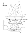
- FIG. 1 is a schematic diagram showing a vehicle equipped with a head-up display in the first embodiment.
- FIG. 2 is a diagram for explaining the configuration of the display unit of the head-up display in the first embodiment.
- FIG. 3A is a diagram illustrating an optical path (an optical path viewed from the Y-axis direction) of the head-up display in the first embodiment.
- FIG. 3B is a diagram illustrating an optical path (an optical path viewed from the X-axis direction) of the head-up display in the first embodiment.
- FIG. 4A is a diagram showing an optical path viewed from the Y-axis direction in the first embodiment.
- FIG. 4B is a diagram for explaining superimposition of optical paths (optical paths viewed from the X-axis direction) of each light source element.
- FIG. 4C is a diagram showing an optical path viewed from the X-axis direction in the first embodiment.
- FIG. 5A is a graph (X-axis direction center portion) showing a distribution of emitted light of the display unit (liquid crystal panel) in the first exemplary embodiment.
- FIG. 5B is a graph (X-axis direction end portion) showing a distribution of emitted light of the display unit (liquid crystal panel) in the first exemplary embodiment.
- FIG. 5C is a graph (Y-axis direction central portion) showing a distribution of emitted light of the display unit (liquid crystal panel) in the first exemplary embodiment.
- FIG. 5A is a graph (X-axis direction center portion) showing a distribution of emitted light of the display unit (liquid crystal panel) in the first exemplary embodiment.
- FIG. 5B is a graph (X
- FIG. 6A is a diagram illustrating an optical path of the head-up display in the first embodiment.
- FIG. 6B is a diagram illustrating an optical path of the head-up display in the first embodiment.
- FIG. 7A is a diagram illustrating lighting control for each eye box region in the second embodiment.
- FIG. 7B is a diagram illustrating lighting control for each eyebox area in the second embodiment.
- the light emitted from the light source is condensed on the diffusion plate by the second condenser lens. Specifically, light from a plurality of light sources (light emitting diodes) is received by each lens of the plurality of lenses provided in the second condenser lens and emitted to the diffusion plate. That is, light from one light source is received by one lens. For this reason, when light emitted from each lens of the condenser lens is incident on the diffuser plate, luminance unevenness occurs in the vicinity of the boundary of the region irradiated with the light emitted from the adjacent lens in the condenser lens. There is a problem of getting.
- one light source illuminates a part of the display element, and light from all the light source elements reaches the entire eye box regardless of the position of the driver's eyes. In other words, light from the light source is incident in addition to the position of the driver's eyes on the eyebox, and there is a lot of wasted light.
- FIG. 1 is a diagram showing a configuration of a head-up display mounted on a vehicle in the first embodiment.
- the head-up display 100 is mounted on a vehicle 200 (an example of a moving body) that includes a windshield 230.
- the head-up display 100 includes a display unit 120, a reflective optical unit 130, a housing 140, and a viewpoint detection unit 800.
- the display unit 120 includes a lighting device 110, a liquid crystal panel 115, and a control unit 700.
- the head-up display 100 is a device that projects an image for allowing the observer 300 to visually recognize the virtual image 400 on the windshield 230.
- the illumination device 110 illuminates a liquid crystal panel 115 which is a display element.
- the liquid crystal panel 115 displays an image indicating a numerical value indicating a speedometer or speed, for example.
- the liquid crystal panel 115 functions as a spatial light modulator, and modulates the light from the illumination device 110 with the displayed image.
- the modulated light is emitted from the liquid crystal panel 115 as transmitted light.
- the transmitted light is guided into the eye box 600 of the observer 300 through the reflective optical unit 130 and the windshield 230, and is visually recognized as a virtual image 400 by the observer 300.
- the observer 300 can visually recognize an image such as a speedometer as the virtual image 400.
- the eye box is a region that the viewer 300 can visually recognize without missing the virtual image 400.
- the reflective optical unit 130 (an example of an optical element) includes a first mirror 131 and a second mirror 132.
- the first mirror 131 reflects the light emitted from the liquid crystal panel 115 toward the second mirror 132.
- the second mirror 132 reflects the light from the first mirror 131 toward the windshield 230.
- the reflection surface of the second mirror 132 has a concave shape.
- the reflective optical unit 130 does not necessarily need to be composed of two mirrors, and may be composed of one mirror or three or more mirrors. Further, a refractive optical system such as a lens may be further disposed on the optical path of the reflective optical unit 130.
- the housing 140 of the head-up display 100 houses the display unit 120 and the reflective optical unit 130, and has an opening 141 through which light from the reflective optical unit 130 is emitted.
- a transparent cover may be provided in the opening 141.
- the control unit 700 is a processor that controls the lighting device 110 and the liquid crystal panel 115.
- the head-up display 100 is controlled based on information from the viewpoint detection unit 800.
- the viewpoint detection unit 800 is a device that is provided inside the vehicle 200 and detects the positions of the left and right eyes of the observer 300.
- the viewpoint detection unit 800 is an imaging device such as a camera or a sensor using infrared rays, for example.
- FIG. 2 is a diagram showing a detailed configuration of the display unit 120.
- the display unit 120 includes a lighting device 110, a liquid crystal panel 115, and a control unit 700.
- the liquid crystal panel 115 has an incident surface 115a for entering light and an exit surface 115b for emitting light.
- the entrance surface 115a and the exit surface 115b have the same shape and a rectangular shape.
- a three-dimensional orthogonal coordinate system is set in the drawing. That is, the X axis is set in a direction parallel to the longitudinal direction of the incident surface 115a and the exit surface 115b in the liquid crystal panel 115, and the Y axis is set in a direction parallel to the width direction of the entrance surface 115a and the exit surface 115b.
- the Z axis is set in the normal direction of 115a and the exit surface 115b.
- the illumination device 110 includes a plurality of light source elements 111, a first lens 112 arranged in the emission direction of the light source element 111, and a second lens 113 arranged in the emission direction of the first lens 112. And a diffusion plate 114 (an example of a diffusion member) disposed in the emission direction of the second lens 113.
- the light source element 111 is, for example, a chip-type light emitting diode (LED), and is a light emitter that supplies illumination light to the liquid crystal panel 115.
- the plurality of light source elements 111 are arranged in a line in the longitudinal direction (X direction in FIG. 3).
- the first lens 112 is disposed close to the light source element 111 so that the light emitted from each light source element 111 does not leak.
- the 1st lens 112 takes in the emitted light of each light source element 111 from the entrance plane 112a. Further, the first lens 112 has a function of deflecting and emitting the diverging light of the light source element 111 into substantially parallel light in the Y direction. Further, only one first lens 112 is disposed for the plurality of light source elements 111.
- At least one of the entrance surface 112a and the exit surface 112b of the first lens 112 has a convex shape so that the first lens 112 has a positive refractive power.
- the convex shapes of the entrance surface 112a and the exit surface 112b of the first lens 112 do not need to be rotationally symmetric with respect to the optical axis, and may be toroidal shapes having different curvatures in the X direction and the Y direction.
- the first lens 112 is a plano-convex lens having a convex shape only on the emission surface 112b.
- the exit surface 112b of the first lens 112 is a convex surface having an aspherical shape with different curvatures in the X-axis direction and the Y-axis direction.
- the shape of the exit surface 112b in the X-axis direction is such that the curvature decreases from the center to the end so that the illuminance distribution on the diffusion plate 114 of the emitted light from each light source element 111 is uniform (that is, the curvature radius is large).
- the shape of the exit surface 112b in the Y-axis direction has such a shape that the curvature of the end portion is smaller than that of the center portion so that the illuminance distribution is uniform on the diffusion plate 114.
- the second lens 113 has a function of deflecting light emitted from the first lens 112 in a desired direction.
- the incident surface 113a of the second lens 113 has a convex shape only in the X-axis direction.
- the shape of the exit surface 113b of the second lens 113 has a convex shape with different curvatures in the X-axis direction and the Y-axis direction.
- the incident surface 113a of the second lens 113 may have a convex shape having different curvatures in the X-axis direction and the Y-axis direction.
- the emission surface 113b of the second lens 113 may have a shape having a convex shape only in one of the X-axis and Y-axis directions.
- the refractive power of the second lens 113 is set according to the emission angle of the emitted light at the end of the display unit 120 (or the incident angle of the incident light on the diffusion plate 114).
- the second lens 113 is not always necessary. By increasing the distance between the first lens 112 and the diffusion plate 114 without using the second lens 113, it is possible to achieve a desired emission angle at the end of the display unit 120 with only the first lens 112. is there.
- the first lens 112 and the second lens 113 are made of a transparent material having a predetermined refractive index.
- the refractive index of the transparent material is, for example, about 1.4 to 1.6.
- a resin such as an epoxy resin, a silicon resin, an acrylic resin, or polycarbonate can be used.
- polycarbonate is used in consideration of heat resistance.
- the diffusion plate 114 diffuses the light deflected by the first lens 112 and the second lens 113 and emits the light to the liquid crystal panel 115. Thereby, the brightness nonuniformity in the image light produced
- the diffusion plate 114 may be an optical member having a function of diffusing light.
- the surface of the diffusion plate 114 is constituted by a bead member, a fine uneven structure, or a rough surface. Further, a dot sheet or a transparent milky white sheet may be used.
- the control unit 700 controls lighting of the plurality of light source elements 111 based on information from the viewpoint detection unit 800 and the liquid crystal panel 115.
- the control unit 700 can be realized by a microcomputer, for example.
- FIG. 3A and 3B are diagrams showing the optical path from the liquid crystal panel 115 to the eye box 600 in the head-up display 100.
- FIG. The observer 300 visually recognizes the light transmitted through the liquid crystal panel 115 through the virtual image optical system 500.
- the virtual image optical system 500 is a combination of the reflective optical unit 130 and the windshield 230 shown in FIG.
- FIG. 3A shows an optical path when viewed from the long side of the liquid crystal panel 115
- FIG. 3B shows an optical path when viewed from the short side of the liquid crystal panel 115.
- the liquid crystal panel 115 When the liquid crystal panel 115 is arranged so that the incident surface 115 a of the liquid crystal panel 115 is parallel to the emission surface of the illumination device 110, the emitted light from the liquid crystal panel 115 toward the center of the eye box 600 is transmitted from the liquid crystal panel 115.
- the light is emitted at different emission angles at the center and the end. Specifically, the emission angle ⁇ 1 at the center of the liquid crystal panel 115 is larger than the emission angle ⁇ 2 at the end of the liquid crystal panel 115.
- the light emitted from the central portion of the liquid crystal panel 115 is emitted in the normal direction of the light emission surface 115b of the liquid crystal panel 115, while the light emitted from the end portion is emitted toward the outside of the light emission surface 115b of the liquid crystal panel 115. Is done. This is not the case when the liquid crystal panel 115 is not arranged in parallel to the illumination device 110, and the outgoing light at the center is inclined with respect to the normal direction of the outgoing surface 115b of the liquid crystal panel 115. Further, since the eye box 600 generally has a length in the X direction larger than a length in the Y direction, the light distribution angle ⁇ 1 in the X axis direction (see FIG. 3A) is the light distribution angle ⁇ 2 in the Y axis direction ( (See FIG. 3B).
- FIG. 4A is a diagram showing an optical path from the light source element 111 to the eye box 600 as seen from the Y-axis direction.
- the first lens 112 deflects the light emitted from each light source element 111 so that each of the light emitted from the plurality of light source elements 111 overlaps at the position of the diffusion plate 114.
- the refractive power of the first lens 112 is set so that each of the plurality of light source elements 111 illuminates the entire surface of the liquid crystal panel 115 when viewed from the Y-axis direction.
- the light emitted from the light source element 111a and the light emitted from the light source element 111c both illuminate the entire area of the liquid crystal panel 115.
- the other light source elements 111b and 111d both illuminate the entire area of the liquid crystal panel 115.
- the focal length of the first lens 112 is set so that the emitted light from each of the light source elements 111a to 111d is irradiated with the same region of the liquid crystal panel 115 superimposed.
- the first lens 112 is designed so that the focal length of the first lens 112 is the same value as the distance from the optical center of the first lens 112 to the liquid crystal panel 115.
- the focal length of the first lens 112 is set to A value larger than the distance from the optical center to the liquid crystal panel 115 may be set.
- the second lens 113 is used to adjust the incident angle of the light emitted from the first lens 112 to the liquid crystal panel 115. That is, the second lens 113 deflects the light emitted from the first lens 112 in a direction inclined at a predetermined angle.
- This predetermined angle is an angle at which the emission angles at the center and the end of the liquid crystal panel 115 as shown in FIGS. 3A and 3B can be obtained. That is, the refractive power of the second lens 113 is set so that the emission angle according to the virtual image optical system 500 is obtained.
- the second lens 113 is not essential.
- the diffuser plate 114 weakens the directivity of light rays incident on the diffuser plate 114.
- the emitted light emitted from the liquid crystal panel 115 has a light distribution characteristic having a peak of light intensity in a direction corresponding to each of the plurality of light sources 111. Due to the presence of the diffusing plate 114, light incident on the liquid crystal panel 115 is diffused and transmitted through the liquid crystal panel 115 to smooth the light distribution characteristics of the emitted light. Light rays emitted from the plurality of light source elements 111 are incident on the diffusion plate 114 at different angles depending on the arrangement positions of the light source elements 111.
- the light distribution angle in the X-axis direction of the diffusing plate 114 is the light distribution angle of the emitted light with respect to a combination of incident light from a plurality of light sources 111 arranged in the X-axis direction. growing. Therefore, a light distribution angle larger than the diffusion characteristic of the diffusion plate 114 can be provided in the X-axis direction compared to the Y-axis direction.
- the light distribution angle of the light emitted from the liquid crystal panel 115 can be controlled by changing the arrangement of the plurality of light source elements 111. By widening the interval between the light source elements 111, the difference in the incident angle to the diffusion plate 114 increases, and the interval at which the peak of the light intensity appears increases.
- the light distribution angle of the liquid crystal panel 115 can be increased by widening the interval between the light source elements 111. However, it is necessary to spread the light emitted from the light source element 111 to such an extent that it does not enter the first lens 112 and does not leak.
- FIG. 4C is a diagram showing an optical path from the light source element 111 to the eye box 600 as seen from the X-axis direction.
- Light emitted from the light source element 111 enters the first lens 112 and is deflected by the second lens 113 to the extent that it becomes an outward light beam.
- virtual image 400 has a long side (side extending in the longitudinal direction of liquid crystal panel 115) and a short side (side extending in the width direction of liquid crystal panel 115).
- the refractive powers of the first lens 112 and the second lens 113 are set so that the light distribution angle of the light emitted from the liquid crystal panel 115 is narrower than that in the X-axis direction.
- the diffusion plate 114 has a function of diffusing and emitting light incident thereon according to a predetermined light distribution characteristic (diffusion angle).
- the light distribution characteristic is set so that the light emitted from the diffusion plate 114 and passing through the virtual image optical system 500 finally has a spread corresponding to the width of the eye box 600.
- the smoothing of the angle characteristic in the X-axis direction may not be completely achieved. is there.
- an anisotropic material having different diffusibility (diffusion angle) in the X-axis direction and the Y-axis direction may be used as the material of the diffusion plate 114.
- an anisotropic material having different diffusibility (diffusion angle) in the X-axis direction and the Y-axis direction may be used.
- the intervals between the plurality of light source elements 111 may be adjusted.
- FIG. 5A is a graph showing the light distribution characteristics of the emitted light at the center in the X-axis direction, which is the longitudinal direction of the liquid crystal panel 115 in the present embodiment.
- FIG. 5B is a graph showing the light distribution characteristics of the emitted light at the end in the X-axis direction, which is the longitudinal direction of the liquid crystal panel 115 in the present embodiment.
- FIG. 5C is a graph showing the light distribution characteristics of the emitted light at the center in the Y-axis direction, which is the width direction of the liquid crystal panel 115 in the present embodiment.
- the vertical axis represents the light intensity of the liquid crystal panel 115
- the unit is candela
- the horizontal axis represents the light distribution angle of the liquid crystal panel 115
- the unit is degrees.
- the central portion of the liquid crystal panel 115 has a peak of the intensity of emitted light in the normal direction of the emission surface 115b of the liquid crystal panel 115, whereas the end portion of the liquid crystal panel 115 has a peak. It can be seen that the intensity of the emitted light has a peak in a direction inclined to the outside of the liquid crystal panel 115 with respect to the normal direction.
- the light distribution angle in the X-axis direction is larger than the light distribution angle in the Y-axis direction.
- Control of light source element 6A and 6B are diagrams schematically illustrating a method for controlling the light source element 111 of the head-up display 100 according to the present embodiment.
- the lighting state of the light source element 111 is controlled by the control unit 700 according to the information on the viewpoint position of the observer 300 obtained by the viewpoint detection unit 800.
- the outgoing lights emitted from the light source elements 111a to 111d are incident on the corresponding positions of the eye box partial regions 600a to 600d, which are obtained by dividing the eye box 600 into a plurality of parts. That is, light from the light source element 111 a located at the end of the light source element 111 is mainly incident on the eye box partial region 600 a at the end of the eye box 600. In addition, 111d light positioned at the end opposite to 111a in the light source element 111 is incident mainly on 600d positioned at the end opposite to the eyebox partial region 600a of the eyebox 600. Note that the positions where the emitted light of the light source elements 111a to 111d is incident are determined by the respective arrangement positions, and the number of partial regions of the eye box 600 can be the same as the number of the light source elements 111.
- the viewpoint detection unit 800 detects in which region of the eyebox partial regions 600a to 600d the left and right eyes of the viewer 300 are located.
- the control unit 700 controls the light intensity of each of the light source elements 111a to 111d according to the position of the eye of the observer 300 detected by the viewpoint detection unit 800. Therefore, the control unit 700 has a table that determines in advance the light source element 111 to be turned on according to the eye position of the observer 300 detected by the viewpoint detection unit 800. In the present embodiment, as shown in FIG.
- the light source element 111a is turned on for 300a
- the light source element 111c is turned on for the right eye 300b
- the light source elements 111b and 111d are turned off.
- the position of the eye of the observer 300 moves from the state of FIG. 6A to the left side of the paper of FIG. 6A (the negative direction of the X coordinate).
- the eye position of the viewer 300 is The light source elements 111a and 111b are turned on for the left eye 300a and the light source elements 111c and 111d are turned on for the right eye 300b with lower light intensity than when located in the center of the eyebox partial region.
- FIG. 6B shows a case where the left eye 300a of the observer moves to the center of the eye box partial area 600b and the right eye 300b of the observer moves to the center of the eye box partial area 600d.
- the light source element 111b is turned on for the left eye 300a
- the light source element 111d is turned on for the right eye 300b
- the light source elements 111a and 111c are turned off.
- the lighting area of the eye box 600 is changed by controlling the lighting state of the light source element 111. This is because each of the light source elements 111a to 111d illuminates the entire area of the liquid crystal panel 115. This is because the first lens 112 and the second lens 113 are configured so that the positions of the eye boxes 600 into which the plurality of light source elements 111a to 111d are incident are different.
- the head-up display 100 projects an image on the eye box 600 of the observer 300.
- the head-up display 100 includes a plurality of light source elements 111, a liquid crystal panel 115 (an example of a transmissive display element), a first lens 112 (an example of an optical member), a viewpoint detection unit 800, and a control unit 700.
- the plurality of light source elements 111 are arranged in an array and emit light.
- the liquid crystal panel 115 displays an image.
- the first lens 112 deflects the light emitted from the plurality of light source elements 111 so as to illuminate the same region on the incident surface 115 a of the liquid crystal panel 115.
- the viewpoint detection unit 800 detects the eye position of the observer 300 (an example of the viewpoint position).
- the control unit 700 controls the plurality of light source elements 111 according to the position of the eye of the observer 300 detected by the viewpoint detection unit 800.
- the observer 300 can visually recognize the virtual image 400 without any change in luminance.
- the head-up display 100 according to the present embodiment is different from the first embodiment in that the light source element 111 includes nine light source elements 111a to 111i, and other configurations are the same as those in the first embodiment. Therefore, the description is omitted.
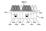
- FIG. 7A and 7B are diagrams showing light intensity distributions in the eyebox partial regions 600a to 600i.
- the intensity of light incident on each light source element 111a to 111i is maximized in the corresponding region of the eye box partial region 600a to 600i of the eye box 600, respectively. Since the light source elements 111a to 111i of the head-up display 100 according to the present embodiment are arranged densely, the light emitted from each of the light source elements 111a to 111i is not only the corresponding eye box partial area but also its adjacent area. It also enters the eyebox partial area.
- FIG. 7A is a diagram showing a light intensity distribution in the eye box 600 when the left eye 300a of the observer 300 is in the eye box partial area 600c and the right eye 300b of the observer 300 is in the eye box partial area 600g. .
- the light source element 111b, the light source element 111c, and the light source element 111d are turned on for the left eye 300a.
- the light source element 111f and the light source element 111h are turned on.
- the light emitted from the light source elements 111a, 111e, and 111i is turned off because it is not incident on the viewpoint position of the observer 300.
- FIG. 7B is a diagram showing a light intensity distribution in the eye box 600 when the observer 300 moves to the left side of the drawing from the state of FIG. 7A. Specifically, a case where the left eye 300a of the observer 300 moves from the eyebox partial area 600c to 600d and the right eye 300b of the observer 300 moves from the eyebox partial area 600g to 600h will be described. In this case, when the left eye 300a of the observer 300 enters the eyebox partial region 600d, the light source element 111e is turned on in addition to the light source elements 111c and 111d for the left eye 300a. Since the light emitted from the light source element 111b is not incident on the left eye 300a, it can be turned off.
- the light source element 111i is turned on in addition to the light source elements 111g and 111h.
- the light source element 111f in which the emitted light is not incident on the right eye 300b is turned off. That is, the light source elements 111a, 111b, and 111f can be turned off. Switching between turning off and turning on is performed by simultaneously controlling the light source element to be turned off and the light source element to be turned on, because the number of light source elements that illuminate the viewpoint position of the viewer 300 does not change. There is no effect on brightness.
- the light intensity distribution for each light source element 111 that is lit is indicated by a solid line. Further, the distribution of the light intensity incident on the eye box 600 is indicated by the hatched portion. That is, the shaded area is a combination of the light intensity distributions indicated by the solid lines. 7A and 7B, as can be seen from the position of the eye of the viewer 300 and the intensity distribution of the shaded area, it is possible to suppress a large change in light intensity around the eye of the viewer 300. Thereby, when the control of the light source element 111 has not completely followed the movement of the eye of the viewer 300, the change in the luminance of the virtual image 400 viewed from the viewer 300 can be suppressed.
- Embodiments 1 and 2 have been described as examples of the technology disclosed in the present application.
- the technology in the present disclosure is not limited to this, and can also be applied to embodiments that have been changed, replaced, added, omitted, and the like.
- the liquid crystal panel 115 is used as the spatial light modulation element, but other display elements can be used as long as they are transmissive display devices.
- liquid crystal panel 115 is arranged so as to be orthogonal to the chief ray of the light source element 111 is shown, it may be arranged not inclined but inclined.
- the focal length of the first lens 112 is changed from the optical center of the first lens 112. You may set to the value more than the distance to the output surface 113b of the 2nd lens 113. FIG. This also makes it possible to generate a virtual image with reduced luminance unevenness.
- one first lens 112 is arranged for a plurality of light source elements 111, but a plurality of first lenses may be arranged for a plurality of light source elements 111.
- the first lens 112 is a convex lens, but a TIR (Total Internal Reflection) lens can also be used. Thereby, the light from the light source element 111 can be efficiently emitted to the second lens 113, and the light utilization efficiency is improved.
- TIR Total Internal Reflection
- the illumination device 110 only one row of light source elements 111 is arranged in the Y-axis direction (the width direction of the liquid crystal panel 115). However, a plurality of light source elements 111 are arranged in the Y-axis direction. Also good.
- the diffusion plate 114 is disposed between the second lens 113 and the liquid crystal panel 115, but the diffusion plate 114 may be disposed between the first lens 112 and the second lens 113. Although inferior in efficiency, luminance unevenness can be reduced even at this position.
- the windshield 230 is exemplified as a member for reflecting the light emitted from the head-up display 100, the present invention is not limited thereto, and a combiner can also be used.
- the LED is exemplified as the light source, a laser diode, an organic light emitting diode, or the like can also be used.
- the head-up display that observes with both eyes has been described as a light source control method, but a head-up display that observes with a single eye can also be realized by controlling in the same manner as described above.
- a conventional monocular head-up display device light may be emitted to both eyes depending on the position of the observer's eyes, and a virtual image may be visually recognized with both eyes, but control is performed as in the present embodiment. Therefore, it becomes easy to irradiate only to a single eye.
- the viewpoint detection unit 800 may not only directly detect the position of the eye, but also may estimate from the eyebrows, the nose, and the contour of the face.
- power saving is achieved by control by turning on and off according to the position of the eyes of the observer, but the light source element 111 may be moved according to the position of the eyes of the observer 300. .
- the light source element that does not reach the eyes of the observer 300 is exemplified to be extinguished.
- the light intensity of the light source element 111 may be turned on and lighted. Thereby, when the eye is positioned at the boundary position of the eyebox partial area, the luminance unevenness can be reduced.
- the display image of the liquid crystal panel 115 can be time-divided to present different images to the left and right eyes for stereoscopic viewing.
- the light source element when displaying an image for the right eye, the light source element is turned on and off so as to illuminate only the eye box partial area where the right eye is located.
- autostereoscopic display is possible.
- the moving body on which the head-up display 100 according to the present embodiment is mounted is not limited to an automobile vehicle, and includes various devices that transport railway vehicles, motorcycles, aircraft, helicopters, ships, and other people.
- the present disclosure can be applied to a projection device that visually recognizes a virtual image. Specifically, the present disclosure is applicable to a head-up display.
- DESCRIPTION OF SYMBOLS 100 Head-up display 110 Illuminating device 111 Light source element 112 1st lens 112a Incident surface 112a (1st lens) Output surface 113b 2nd lens 113a (2nd lens) Incident surface 113b (2nd lens) Outgoing surface 114 Diffusion plate (Diffusion member) 115 liquid crystal panel 115a incident surface (liquid crystal panel) incident surface 115b (liquid crystal panel) output surface 120 display unit 130 reflective optical unit 131 first mirror 132 second mirror 140 housing 141 opening 200 vehicle 230 windshield 300 observer 300a left eye 300b Right eye 400 Virtual image 500 Virtual image optical system 600 Eye box 700 Control unit
Abstract
ヘッドアップディスプレイは、観察者のアイボックスに画像を投射するものである。ヘッドアップディスプレイは、複数の光源素子と、液晶パネル(115)と、第1レンズ(112)と、視点検出部(800)と、制御部(700)と、を備える。複数の光源素子は、アレイ状に配置され、光を出射する。液晶パネル(115)は、画像を表示する第1レンズ(112)は、複数の光源素子から出射された光を液晶パネル(115)の入射面における同一の領域に照明するように偏向する。視点検出部(800)は、観察者の視点位置を検出する。制御部(700)は、視点検出部(800)の検出した視点位置に応じて、光源素子の光の強度を制御する。
Description
本開示は、観察者に虚像を視認させるための画像を表示するヘッドアップディスプレイに関する。
特許文献1は、液晶パネルの背後の光源から出る光を均一化して、液晶パネルを透過照明するヘッドアップディスプレイを開示する。このヘッドアップディスプレイは、光源(発光ダイオード)と、第1の集光レンズと、拡散板と、第2の集光レンズとを備える。第2集光レンズは、光源から発する光を拡散板へ集光させている。これにより、表示器を透過する照明光の輝度の低下を抑えつつ、その輝度ムラを低減させることができる。
本開示の第一の態様におけるヘッドアップディスプレイは、観察者のアイボックスに画像を投射するものである。ヘッドアップディスプレイは、複数の光源素子と、透過型表示素子と、光学部材と、視点検出部と、制御部と、を備える。複数の光源素子は、アレイ状に配置され、光を出射する。透過型表示素子は、画像を表示する。光学部材は、複数の光源素子から出射された光を透過型表示素子の入射面における同一の領域に照明するように偏向する。視点検出部は、観察者の目の位置を検出する。制御部は、視点検出部の検出した視点位置に応じて、光源素子の光の強度を制御する。
本開示の第二の態様において、上記のヘッドアップディスプレイを備えた移動体(自動車、鉄道車両、航空機、船舶等)が提供される。
本開示におけるヘッドアップディスプレイは、観察者の眼の位置に応じて光源の点灯を制御して、省電力化を図ることができる。
以下、適宜図面を参照しながら、実施の形態を詳細に説明する。但し、必要以上に詳細な説明は省略する場合がある。例えば、既によく知られた事項の詳細説明や実質的に同一の構成に対する重複説明を省略する場合がある。これは、以下の説明が不必要に冗長になるのを避け、当業者の理解を容易にするためである。なお、添付図面および以下の説明は、当業者が本開示を十分に理解するために、提供されるのであって、これらにより請求の範囲に記載の主題を限定することは意図されていない。
特許文献1のヘッドアップディスプレイでは、第2集光レンズにより光源(発光ダイオード)から発する光を拡散板へ集光させている。具体的には、複数の光源(発光ダイオード)からの光を、第2集光レンズに設けられた複数のレンズのそれぞれのレンズで受けて拡散板へ出射している。すなわち、一つの光源からの光を一つのレンズで受けている。このため、集光レンズの各レンズから出射された光が拡散板へ入射される際に、集光レンズ内の隣接するレンズから出射される光が照射される領域の境界近傍で輝度ムラが生じ得るという問題がある。また、1つの光源が表示素子の一部分を照明するような構成となっており、運転者の眼の位置に因らず、全ての光源素子の光がアイボックス全域に届く。換言すると、アイボックス上の運転者の眼の位置以外にも光源の光が入射しており、無駄となる光が多く存在した。
(実施の形態1)
以下、添付の図面を用いて実施の形態1を説明する。
以下、添付の図面を用いて実施の形態1を説明する。
[1-1.構成]
[1-1-1.全体構成]
図1は、実施の形態1における、車両に搭載されたヘッドアップディスプレイの構成を示した図である。ヘッドアップディスプレイ100は、ウインドシールド230を備える車両200(移動体の一例)に搭載されている。ヘッドアップディスプレイ100は、表示ユニット120と、反射光学ユニット130と、筐体140と、視点検出部800とから構成される。表示ユニット120は、照明装置110と、液晶パネル115と、制御部700とを含む。
[1-1-1.全体構成]
図1は、実施の形態1における、車両に搭載されたヘッドアップディスプレイの構成を示した図である。ヘッドアップディスプレイ100は、ウインドシールド230を備える車両200(移動体の一例)に搭載されている。ヘッドアップディスプレイ100は、表示ユニット120と、反射光学ユニット130と、筐体140と、視点検出部800とから構成される。表示ユニット120は、照明装置110と、液晶パネル115と、制御部700とを含む。
ヘッドアップディスプレイ100は、観察者300に虚像400を視認させるための画像をウインドシールド230に投影する装置である。
照明装置110は表示素子である液晶パネル115を照明する。液晶パネル115は例えばスピードメータまたはスピードを示す数値を示す画像を表示する。液晶パネル115は空間光変調素子として機能し、照明装置110からの光を、表示した画像で変調する。変調された光は、透過光として液晶パネル115から出射される。透過光は、反射光学ユニット130、ウインドシールド230を介して、観察者300のアイボックス600内に導かれ、観察者300に虚像400として視認される。例えば、観察者300は、スピードメータ等の画像を虚像400として視認することができる。ここで、アイボックスとは、観察者300が虚像400を欠けることなく視認できる領域のことである。
反射光学ユニット130(光学素子の一例)は、第1ミラー131および第2ミラー132を備える。第1ミラー131は、液晶パネル115から出射された光を第2ミラー132に向けて反射する。第2ミラー132は、第1ミラー131からの光をウインドシールド230に向けて反射する。第2ミラー132の反射面は、凹面形状を有している。反射光学ユニット130は、必ずしもミラー2枚で構成される必要はなく、1枚のミラーまたは3枚以上のミラーで構成されても良い。また、反射光学ユニット130の光路上に、レンズなどの屈折光学系をさらに配置しても良い。
ヘッドアップディスプレイ100の筐体140は、表示ユニット120と反射光学ユニット130を収納し、反射光学ユニット130からの光が出射する開口141を有している。開口141には、透明のカバーを設けてもよい。
制御部700は、照明装置110や液晶パネル115を制御するプロセッサである。また、視点検出部800からの情報を基に、ヘッドアップディスプレイ100を制御する。
視点検出部800は、車両200の内部に設けられており、観察者300の左右の眼の位置を検出する装置である。視点検出部800は、例えばカメラ等の撮像装置や赤外線を用いたセンサなどである。
[1-1-2.表示ユニットの構成]
図2は、表示ユニット120の詳細な構成を示す図である。表示ユニット120は、照明装置110と、液晶パネル115と、制御部700とを含む。液晶パネル115は光を入射する入射面115aと、光を出射する出射面115bとを有する。入射面115aと出射面115bは同じ形状を有し、長方形形状を有する。
図2は、表示ユニット120の詳細な構成を示す図である。表示ユニット120は、照明装置110と、液晶パネル115と、制御部700とを含む。液晶パネル115は光を入射する入射面115aと、光を出射する出射面115bとを有する。入射面115aと出射面115bは同じ形状を有し、長方形形状を有する。
なお、以下の説明において、図面中に3次元直交座標系を設定している。すなわち、液晶パネル115における入射面115a及び出射面115bの長手方向に平行な方向にX軸を設定し、入射面115a及び出射面115bの幅方向に平行な方向にY軸を設定し、入射面115a及び出射面115bの法線方向にZ軸を設定している。
図2に示すように、照明装置110は、複数の光源素子111と、光源素子111の出射方向に配置された第1レンズ112と、第1レンズ112の出射方向に配置された第2レンズ113と、第2レンズ113の出射方向に配置された拡散板114(拡散部材の一例)とによって構成される。
光源素子111は、例えばチップ型発光ダイオード(LED)であり、液晶パネル115に照明光を供給する発光体である。複数の光源素子111は長手方向(図3のX方向)において一列に配置されている。
第1レンズ112は、各光源素子111の出射光が漏れない程度に光源素子111に近接させて配置されている。第1レンズ112は、各光源素子111の出射光を入射面112aから取り込む。また、第1レンズ112は、Y方向において、発散する光源素子111の光を略平行光に偏向して出射する機能を有している。また、第1レンズ112は、複数の光源素子111に対して1つだけ配置される。
第1レンズ112の入射面112aまたは出射面112bの少なくともいずれかは、第1レンズ112が正の屈折力を有するように凸形状を有している。なお、第1レンズ112の入射面112aおよび出射面112bの凸形状は光軸に対して回転対称である必要はなく、X方向とY方向で曲率の異なるトロイダル形状であってもよい。本実施の形態では、第1レンズ112は、出射面112bのみ凸形状を有している平凸レンズである。
第1レンズ112の出射面112bは、X軸方向とY軸方向とで曲率が異なる、非球面形状を有する凸面である。出射面112bのX軸方向の形状は、各光源素子111からの出射光の拡散板114上での照度分布が均一となるように、中心から端にかけて曲率が小さくなるよう(すなわち曲率半径が大きくなるよう)な形状を有する。また、出射面112bのY軸方向の形状は、拡散板114上で照度分布が均一となるように、中央部に比べて端部の曲率が小さくなるような形状を有する。
第2レンズ113は、第1レンズ112の出射光を所望の方向に偏向する機能を有している。本実施の形態では、第2レンズ113の入射面113aはX軸方向のみ凸形状を有している。また、第2レンズ113の出射面113bの形状は、X軸方向とY軸方向とで曲率の異なる凸面形状を有する。なお、第2レンズ113の入射面113aは、X軸方向とY軸方向とで曲率の異なる凸面形状を有してもよい。また、第2レンズ113の出射面113bは、X軸およびY軸方向のどちらか一方にのみ凸形状を有する形状を有してもよい。第2レンズ113の屈折力は、表示ユニット120の端部における出射光の出射角(または拡散板114への入射光の入射角)に応じて設定される。なお、第2レンズ113は必ずしも必要ではない。第2レンズ113を用いずに、第1レンズ112と拡散板114までの距離を長くすることにより、第1レンズ112のみで表示ユニット120の端部における所望の出射角を実現することも可能である。
第1レンズ112および第2レンズ113は、所定の屈折率を有する透明材料で構成される。透明材料の屈折率は、例えば1.4から1.6程度である。このような透明材料としては、エポキシ樹脂、シリコン樹脂、アクリル樹脂、ポリカーボネイト等の樹脂を用いることができる。本実施の形態では、耐熱性を考慮してポリカーボネイトを用いている。
拡散板114は、第1レンズ112および第2レンズ113で偏向した光を拡散させて液晶パネル115に出射する。これにより、アイボックス600で視認される複数の光源素子111により生成される映像光における輝度ムラを低減できる。拡散板114は、光を拡散させる機能がある光学部材であれば良く、例えばその表面がビーズ部材や微細な凹凸構造、粗面で構成される。また、ドットシートや透過性の乳白色のシートでも良い。
制御部700は、視点検出部800や液晶パネル115の情報に基づき、複数の光源素子111の点灯を制御する。制御部700は、例えばマイコンによって実現できる。
[1-1-3.ヘッドアップディスプレイにおける光路]
以下、本実施の形態のヘッドアップディスプレイ100における光源素子111から出射された光の光路について説明する。
以下、本実施の形態のヘッドアップディスプレイ100における光源素子111から出射された光の光路について説明する。
図3Aおよび図3Bは、ヘッドアップディスプレイ100における液晶パネル115からアイボックス600までの光路を示した図である。観察者300は液晶パネル115の透過光を、虚像光学系500を介して視認する。虚像光学系500は、図1で示す反射光学ユニット130とウインドシールド230を合わせたものである。図3Aは液晶パネル115の長辺側から見たときの光路を示し、図3Bは液晶パネル115の短辺側から見たときの光路を示している。
液晶パネル115の入射面115aが照明装置110の出射面に対して平行となるように液晶パネル115が配置される場合、液晶パネル115からアイボックス600の中央に向かう出射光は、液晶パネル115の中央部と端部とで異なる出射角で出射される。具体的には、液晶パネル115の中央部での出射角α1は、液晶パネル115の端部での出射角α2よりも大きい。すなわち、液晶パネル115の中央部の出射光は、液晶パネル115の出射面115bの法線方向に出射され、他方、端部の出射光は、液晶パネル115の出射面115bの外側に向かって出射される。液晶パネル115が照明装置110に対して平行に配置されない場合はこの限りではなく、中央部の出射光は、液晶パネル115の出射面115bの法線方向に対して傾きを持つ。また、アイボックス600は、一般的にX方向の長さがY方向の長さよりも大きいため、X軸方向の配光角β1(図3A参照)の方がY軸方向の配光角β2(図3B参照)よりも大きくなる。
図4Aは、Y軸方向から見た、光源素子111からアイボックス600までの光路を示す図である。第1レンズ112は、複数の光源素子111からの出射光のそれぞれが拡散板114の位置で重畳するように、各光源素子111からの出射光を偏向する。
すなわち、第1レンズ112は、Y軸方向から見たとき、複数の光源素子111のそれぞれが液晶パネル115の全面を照明するように、その屈折力が設定されている。例えば、図4Bに示すように、光源素子111aからの出射光と、光源素子111cからの出射光とは、双方とも、液晶パネル115全体の領域を照明する。他の光源素子111b、111dも同様である。
このように、複数の光源素子111それぞれからの光線が液晶パネル115全体(同じ領域)を重畳して照射する。よって、アイボックス600内で視認できる虚像400の輝度が均一になる。
第1レンズ112は、各光源素子111a~111dからの出射光が液晶パネル115の同じ領域を重畳して照射されるようにするために、その焦点距離が設定される。具体的には、第1レンズ112の焦点距離が、第1レンズ112の光学中心から液晶パネル115までの距離と同じ値になるように、第1レンズ112は設計される。
なお、複数の光源素子111のそれぞれから出射された出射光が液晶パネル115のほぼ同じ領域を重畳して照射することができるのであれば、第1レンズ112の焦点距離を、第1レンズ112の光学中心から液晶パネル115までの距離よりも大きい値に設定してもよい。
第2レンズ113は、第1レンズ112からの出射光の液晶パネル115への入射角を調整するために使用されている。すなわち、第2レンズ113は、第1レンズ112からの出射光を、所定の角度に傾けた方向に偏向する。この所定の角度は、図3A、図3Bで示すような液晶パネル115の中央部と端部における出射角が得られるような角度である。すなわち、虚像光学系500に応じた出射角となるように、第2レンズ113の屈折力が設定される。前述のように、第2レンズ113は必須のものではない。
拡散板114は、拡散板114に入射する光線の指向性を弱める。拡散板114がない場合、液晶パネル115から出射される出射光は、複数の光源111のそれぞれに対応した方向に、光強度のピークを有する配光特性をもつ。拡散板114があることにより、液晶パネル115に入射する光線が拡散され、液晶パネル115を透過して出射光の配光特性が平滑化される。複数の光源素子111から出射される光線は、それぞれの光源素子111の配置位置に応じて異なる角度で拡散板114に入射する。拡散板114のX軸方向の配光角は、X軸方向に並んだ複数の光源111からの入射光を合成したものに対する出射光の配光角であるため、拡散板114そのものの拡散特性より大きくなる。そのため、Y軸方向に比べて、X軸方向では拡散板114の拡散特性より大きな配光角を持たせることができる。なお、液晶パネル115の出射光の配光角は、複数の光源素子111の配置を変えることにより制御できる。光源素子111の間隔を広げることにより、拡散板114への入射角の差が大きくなり、光強度のピークが現れる間隔が広がる。従って、同数の光源素子111を用いる場合、光源素子111の間隔を広げることで、液晶パネル115の配光角を大きくすることができる。ただし、光源素子111の出射光が第1レンズ112に入らず漏れることがない程度に、広げる必要がある。
図4Cは、X軸方向から見た、光源素子111からアイボックス600までの光路を示す図である。光源素子111の出射光は、第1レンズ112に入射し、第2レンズ113で外向きの光線となる程度に偏向する。本実施の形態では、虚像400は長辺(液晶パネル115の長手方向に延びる辺)と短辺(液晶パネル115の幅方向に延びる辺)を有しており、照明装置110の短辺方向を示すY軸方向では、X軸方向に比べて液晶パネル115の出射光の配光角を狭くなるように第1レンズ112及び第2レンズ113の屈折力を設定している。
拡散板114は、それに入射した光を所定の配光特性(拡散角)にしたがい拡散して出射する機能を有する。その配光特性は、拡散板114から出射し虚像光学系500を通過した光が最終的にアイボックス600の幅に対応する広がりを有するように設定される。なお、拡散板114において、アイボックス600のY軸方向の幅に対応する広がりを実現するような配光特性を設定した場合、X軸方向の角度特性の平滑化が完全には達成されない場合がある。この場合、拡散板114の材料として、X軸方向とY軸方向とでその拡散性(拡散角)が異なる異方性のある材料を用いてもよい。または、複数の光源素子111の間隔を調整して配置してもよい。
図5Aは、本実施の形態における液晶パネル115の長手方向であるX軸方向中央部の出射光の配光特性を示すグラフである。図5Bは、本実施の形態における液晶パネル115の長手方向であるX軸方向端部の出射光の配光特性を示すグラフである。図5Cは、本実施の形態における液晶パネル115の幅方向であるY軸方向中央部の出射光の配光特性を示すグラフである。図5Aから図5Cのグラフの縦軸は、液晶パネル115の光の強度を示し、単位はカンデラであり、横軸は、液晶パネル115の光の配光角度を示し、単位は度である。
図5Aと図5Bを参照すると、液晶パネル115の中央部においては液晶パネル115の出射面115bの法線方向において出射光の強度のピークを有するのに対して、液晶パネル115の端部においては、出射光の強度は、法線方向を基準として液晶パネル115の外側に傾く方向にピークを有することが分かる。また、図5Aと図5Cに示すとおり、本実施の形態の液晶パネル115では、X軸方向の配光角のほうが、Y軸方向の配光角より大きくなっている。これにより、液晶パネル115の面積よりも大きな虚像400を表示するヘッドアップディスプレイ100において、アイボックス600内で輝度分布の均一な虚像を視認させることができる。
[1-2.光源素子の制御]
図6A、図6Bは、本実施の形態におけるヘッドアップディスプレイ100の光源素子111の制御方法を模式的に表した図である。本実施の形態では、視点検出部800で得られた観察者300の視点位置の情報に応じて、制御部700により光源素子111の点灯状態を制御する。
図6A、図6Bは、本実施の形態におけるヘッドアップディスプレイ100の光源素子111の制御方法を模式的に表した図である。本実施の形態では、視点検出部800で得られた観察者300の視点位置の情報に応じて、制御部700により光源素子111の点灯状態を制御する。
光源素子111a~111dから出射される出射光は、それぞれアイボックス600を複数に分割した、アイボックス部分領域600a~600dの対応する位置に入射する。すなわち、光源素子111の中でも端部に位置する光源素子111aの光は、主にアイボックス600の端部のアイボックス部分領域600aに入射する。また、光源素子111のうち111aと反対の端部に位置する111dの光は、主にアイボックス600のアイボックス部分領域600aとは反対の端部に位置する600dに入射する。なお、光源素子111a~111dの出射光が入射する位置は、それぞれの配置位置によって決まり、アイボックス600の部分領域の数は、光源素子111の数と同数とすることができる。
視点検出部800は、観察者300の左右の眼がアイボックス部分領域600a~600dのどの領域に位置しているかを検出する。制御部700は、視点検出部800によって検出された観察者300の眼の位置に応じて各光源素子111a~111dの光の強度を制御する。そのため、制御部700は、あらかじめ、視点検出部800が検出する観察者300の眼の位置に応じた点灯させる光源素子111を決定するテーブルを有している。本実施の形態では、図6Aに示すように、アイボックス部分領域600aの中心に観察者300の左眼300a、アイボックス部分領域600cの中心に観察者300の右眼300bがある場合、左眼300a用に光源素子111aを、右眼300b用に光源素子111cを、点灯させ、光源素子111bと111dを消灯させる。
図6Aの状態から図6Aの紙面の左方向(X座標の負の方向)に観察者300の眼の位置が移動した場合を説明する。例えば、アイボックス部分領域600aと600bの境界に観察者300の左眼300a、アイボックス部分領域600cと600dの境界に観察者300の右眼300bが位置した場合、観察者300の眼の位置がアイボックス部分領域の中心に位置するときよりも低い光の強度で、左眼300a用に光源素子111aと111bを、右眼300b用に光源素子111cと111dを、それぞれ点灯させる。
さらに、上記の状態から紙面の左方向(X座標の負の方向)に移動した場合について説明する。図6Bは、アイボックス部分領域600bの中心に観察者の左眼300a、アイボックス部分領域600dの中心に観察者の右眼300bが位置するように移動した場合を示している。このとき、左眼300a用に光源素子111bを、右眼300b用に光源素子111dを点灯させ、光源素子111aと111cを消灯させる。
本実施の形態では、光源素子111の点灯状態を制御することで、アイボックス600の照明領域を変更しているが、これは各光源素子111a~111dがそれぞれ液晶パネル115の全域を照明しつつ、複数の光源素子111a~111dがそれぞれ入射するアイボックス600の位置が異なるように、第1レンズ112と第2レンズ113を構成しているためである。
[1-3.効果等]
以上のように、本実施の形態において、ヘッドアップディスプレイ100は、観察者300のアイボックス600に画像を投射するものである。ヘッドアップディスプレイ100は、複数の光源素子111と、液晶パネル115(透過型表示素子の一例)と、第1レンズ112(光学部材の一例)と、視点検出部800と、制御部700と、を備える。複数の光源素子111は、アレイ状配置され、光を出射する。液晶パネル115は、画像を表示する。第1レンズ112は、複数の光源素子111から出射された光を液晶パネル115の入射面115aにおける同一の領域に照明するように偏向する。視点検出部800は、観察者300の眼の位置(視点位置の一例)を検出する。制御部700は、視点検出部800の検出した観察者300の眼の位置に応じて、複数の光源素子111を制御する。
以上のように、本実施の形態において、ヘッドアップディスプレイ100は、観察者300のアイボックス600に画像を投射するものである。ヘッドアップディスプレイ100は、複数の光源素子111と、液晶パネル115(透過型表示素子の一例)と、第1レンズ112(光学部材の一例)と、視点検出部800と、制御部700と、を備える。複数の光源素子111は、アレイ状配置され、光を出射する。液晶パネル115は、画像を表示する。第1レンズ112は、複数の光源素子111から出射された光を液晶パネル115の入射面115aにおける同一の領域に照明するように偏向する。視点検出部800は、観察者300の眼の位置(視点位置の一例)を検出する。制御部700は、視点検出部800の検出した観察者300の眼の位置に応じて、複数の光源素子111を制御する。
このようにすることで、アイボックス部分領域600aと600cのみが照明装置110によって選択的に照明され、観察者300は虚像400を視認することが可能となる。一方、観察者の眼が位置しないアイボックス部分領域600bと600dはほぼ照明されることがないため省電力化が図れる。
また、アイボックス部分領域の境界に眼が位置する場合であっても、観察者300は虚像400を輝度変化なく視認することができる。
(実施の形態2)
[2-1.構成]
本実施の形態におけるヘッドアップディスプレイ100は、光源素子111が9個の光源素子111a~111iによって構成されている点において、実施の形態1と異なり、それ以外の構成は、実施の形態1と同様であるため、説明を省略する。
[2-1.構成]
本実施の形態におけるヘッドアップディスプレイ100は、光源素子111が9個の光源素子111a~111iによって構成されている点において、実施の形態1と異なり、それ以外の構成は、実施の形態1と同様であるため、説明を省略する。
図7A、図7Bは、各アイボックス部分領域600a~600iにおける光の強度分布を示す図である。各光源素子111a~111iが入射する光の強度は、それぞれアイボックス600のアイボックス部分領域600a~600iの対応する領域において最大となる。本実施の形態におけるヘッドアップディスプレイ100の各光源素子111a~111iは、それぞれ密に配置されているため、各光源素子111a~111iの出射光は、対応するアイボックス部分領域だけでなく、その隣接するアイボックス部分領域にも入射する。
図7Aは、アイボックス部分領域600cに観察者300の左眼300a、アイボックス部分領域600gに観察者300の右眼300bがあるときの、アイボックス600における光の強度の分布を示す図である。このとき、左眼300a用には、光源素子111bと光源素子111cと光源素子111dとを点灯させる。また、右眼300b用には、光源素子111f光源素子111gと光源素子111hとを点灯させる。このとき、光源素子111a、111e、111iの出射光は、観察者300の視点位置に入射していないため消灯する。
図7Bは、図7Aの状態から、観察者300が紙面左側へ移動したときのアイボックス600における光の強度の分布を示す図である。具体的には、観察者300の左眼300aがアイボックス部分領域600cから600dへ、観察者300の右眼300bがアイボックス部分領域600gから600hへ移動した場合について説明する。この場合、観察者300の左眼300aがアイボックス部分領域600dに入った時点で、左眼300a用として、光源素子111c、111dに加えて、光源素子111eを点灯させる。光源素子111bの出射光、は左眼300aに入射していないため消灯させることができる。また、右眼300b用に点灯させる光源についても同様に、光源素子111g、111hに加えて、光源素子111iを点灯させる。さらに、出射光が右眼300bに入射していない光源素子111fを消灯する。すなわち、光源素子111a、111b、111fを消灯することができる。消灯と点灯の切り替えは、消灯する光源素子と点灯する光源素子が同時に制御されれば、観察者300の視点位置を照明する光源素子の数が変わらないため、観察者300の視認する虚像400の輝度には影響がない。
[2-2.効果]
上記した構成によれば、観察者300の眼が位置するアイボックス部分領域のみが照明装置110によって選択的に照明され、観察者300は虚像400を視認することが可能となる。一方、観察者300の眼が位置しないアイボックス部分領域は照明する光源素子111を消灯させるため、省電力化が図れる。
上記した構成によれば、観察者300の眼が位置するアイボックス部分領域のみが照明装置110によって選択的に照明され、観察者300は虚像400を視認することが可能となる。一方、観察者300の眼が位置しないアイボックス部分領域は照明する光源素子111を消灯させるため、省電力化が図れる。
図7A及び図7Bにおいて、点灯している光源素子111ごとの光強度の分布を実線で示している。さらに、アイボックス600に入射している光強度の分布は、斜線部で示されている。すなわち、斜線部は、実線で示された光強度の分布を合成したものである。図7A及び図7Bにおいて、観察者300の眼の位置と、斜線部の強度分布とから分かるように、観察者300の眼の周辺において光強度が大きく変化することを抑えられる。これにより、観察者300の眼の移動に対して、光源素子111の制御が完全に追従できていない場合に、観察者300から見た虚像400の輝度の変化を抑えることができる。
(他の実施の形態)
以上のように、本出願において開示する技術の例示として、実施の形態1および2を説明した。しかしながら、本開示における技術は、これに限定されず、変更、置き換え、付加、省略などを行った実施の形態にも適用できる。また、上記実施の形態で説明した各構成要素を組み合わせて、新たな実施の形態とすることも可能である。そこで、以下、他の実施の形態を例示する。
以上のように、本出願において開示する技術の例示として、実施の形態1および2を説明した。しかしながら、本開示における技術は、これに限定されず、変更、置き換え、付加、省略などを行った実施の形態にも適用できる。また、上記実施の形態で説明した各構成要素を組み合わせて、新たな実施の形態とすることも可能である。そこで、以下、他の実施の形態を例示する。
上記の実施の形態では、空間光変調素子として液晶パネル115を用いたが、透過型の表示装置であれば他の表示素子を用いることもできる。
また、液晶パネル115は光源素子111の主光線に対して直交するように配置した例を示したが、直交でなく、傾いて配置することもできる。
第1レンズ112、第2レンズ113の出射面および入射面には、フレネルレンズを用いることも可能である。これにより、レンズの薄型化が達成できる。
また、複数の光源素子111それぞれからの出射光が液晶パネル115のほぼ同じ領域を重畳して照射することができるのであれば、第1レンズ112の焦点距離を、第1レンズ112の光学中心から第2レンズ113の出射面113bまでの距離以上の値に設定してもよい。これによっても、輝度ムラが低減した虚像の生成が可能になる。
上記の実施の形態では、複数の光源素子111に対して一つの第1レンズ112を配置したが、複数の光源素子111に対して複数の第1レンズを配置してもよい。
第1レンズ112は、凸レンズを用いたが、TIR(Total Internal Reflection)レンズを用いることもできる。これにより、光源素子111からの光を効率良く第2レンズ113に出射することができ、光利用効率が向上する。
上記の実施形態では、照明装置110において、Y軸方向(液晶パネル115の幅方向)には光源素子111は一列しか配置されていないが、Y軸方向において、光源素子111を複数列配置してもよい。
上記の実施形態では、拡散板114を第2レンズ113と液晶パネル115の間に配置したが、拡散板114は第1レンズ112と第2レンズ113の間に配置してもよい。効率の点では劣るが、この位置であっても輝度ムラを低減することはできる。
ヘッドアップディスプレイ100の出射光を反射させる部材として、ウインドシールド230を例示したが、これに限られず、コンバイナを用いることもできる。
光源として、LEDを例示したが、レーザーダイオードや有機発光ダイオードなどを用いることもできる。
実施の形態1~2では光源の制御方法として、両眼で観察するヘッドアップディスプレイについて説明したが、単眼で観察するヘッドアップディスプレイにおいても上記と同じように制御することで実現できる。従来の単眼ヘッドアップディスプレイ装置では、観察者の眼の位置によっては両眼に光が照射されて、両眼で虚像を視認してしまう場合があるが、本実施の形態のように制御することで、単眼のみに照射することが容易となる。
視点検出部800は眼の位置を検出するために、直接的に眼の位置を検出するだけでなく、眉間や鼻、顔の輪郭から推定しても良い。
実施の形態1~2では、観察者の眼の位置に応じて点灯と消灯による制御によって省電力化を図ったが、光源素子111を観察者300の眼の位置に応じて移動させてもよい。
実施の形態2では、観察者300の眼に届かない光源素子を消灯させると例示したが、光源素子111の光の強度を抑えて点灯させてもよい。これにより、アイボックス部分領域の境界位置に眼が位置する場合に、輝度ムラを低減することができる。
液晶パネル115の表示画像を時分割して左右の眼に異なる画像を提示して立体視させることも可能である。この場合、右眼用画像を表示する時には、右眼が位置するアイボックス部分領域のみを照明するように光源素子の点灯と消灯を制御し、反対に左眼用画像を表示する時には、左眼が位置するアイボックス部分領域のみを照明するように光源素子の点灯と消灯を制御することで、裸眼立体表示が可能となる。
本実施の形態のヘッドアップディスプレイ100が搭載される移動体は、自動車の車両に限られず、鉄道車両、バイク、航空機、ヘリコプター、船舶、及びその他の人を搬送する各種の装置を含む。
本開示は、虚像を視認させる投映装置に適用可能である。具体的には、ヘッドアップディスプレイ、などに、本開示は適用可能である。
100 ヘッドアップディスプレイ
110 照明装置
111 光源素子
112 第1レンズ
112a (第1レンズの)入射面
112b (第1レンズの)出射面
113 第2レンズ
113a (第2レンズの)入射面
113b (第2レンズの)出射面
114 拡散板(拡散部材)
115 液晶パネル
115a (液晶パネルの)入射面
115b (液晶パネルの)出射面
120 表示ユニット
130 反射光学ユニット
131 第1ミラー
132 第2ミラー
140 筐体
141 開口
200 車両
230 ウインドシールド
300 観察者
300a 左眼
300b 右眼
400 虚像
500 虚像光学系
600 アイボックス
700 制御部
Claims (8)
- 観察者のアイボックスに画像を投射するヘッドアップディスプレイであって、
アレイ状に配置され、光を出射する複数の光源素子と、
画像を表示する透過型表示素子と、
前記複数の光源素子から出射された光を前記透過型表示素子の入射面における同一の領域に照明するように偏向する光学部材と、
観察者の視点位置を検出する視点検出部と、
前記視点検出部の検出した視点位置に応じて、前記光源素子の光の強度を制御する制御部と、を備える、
ヘッドアップディスプレイ。 - 前記光学部材の焦点距離は、前記光学部材の光学中心から前記透過型表示素子までの距離以上の値に設定される、請求項1に記載のヘッドアップディスプレイ。
- 前記光学部材は、レンズ素子で構成される、
請求項1に記載のヘッドアップディスプレイ。 - 前記光学部材は、第1レンズ素子と、前記第1レンズ素子の出射面側に配置される第2レンズとを備える、
請求項1に記載のヘッドアップディスプレイ。 - 前記複数の光源素子の出射光の少なくとも一部は、それぞれ前記アイボックスにおける異なる領域に入射し、
前記制御部は、前記複数の光源素子のうち、前記アイボックスにおける前記観察者の視点位置のない領域に投射する前記光源素子を消灯する、
請求項1に記載のヘッドアップディスプレイ。 - 前記制御部は、前記観察者の視点位置が前記アイボックスにおける複数の領域の境界に位置した時に、前記観察者の視点位置が前記アイボックスにおける複数の領域の境界に位置しない時に比べて、前記光源素子の出射光の強度を低くする、
請求項1に記載のヘッドアップディスプレイ。 - ウインドシールドを有する移動体に搭載される、請求項1に記載のヘッドアップディスプレイ。
- 請求項1に記載のヘッドアップディスプレイを搭載した移動体。
Priority Applications (3)
| Application Number | Priority Date | Filing Date | Title |
|---|---|---|---|
| JP2017526172A JP6586646B2 (ja) | 2015-07-01 | 2016-06-24 | ヘッドアップディスプレイ及びヘッドアップディスプレイを備えた移動体 |
| EP16817455.5A EP3287834B1 (en) | 2015-07-01 | 2016-06-24 | Head-up display and moving body comprising head-up display |
| US15/839,489 US10302943B2 (en) | 2015-07-01 | 2017-12-12 | Head-up display and moving body comprising head-up display |
Applications Claiming Priority (2)
| Application Number | Priority Date | Filing Date | Title |
|---|---|---|---|
| JP2015132282 | 2015-07-01 | ||
| JP2015-132282 | 2015-07-01 |
Related Child Applications (1)
| Application Number | Title | Priority Date | Filing Date |
|---|---|---|---|
| US15/839,489 Continuation US10302943B2 (en) | 2015-07-01 | 2017-12-12 | Head-up display and moving body comprising head-up display |
Publications (1)
| Publication Number | Publication Date |
|---|---|
| WO2017002344A1 true WO2017002344A1 (ja) | 2017-01-05 |
Family
ID=57608187
Family Applications (1)
| Application Number | Title | Priority Date | Filing Date |
|---|---|---|---|
| PCT/JP2016/003053 WO2017002344A1 (ja) | 2015-07-01 | 2016-06-24 | ヘッドアップディスプレイ及びヘッドアップディスプレイを備えた移動体 |
Country Status (4)
| Country | Link |
|---|---|
| US (1) | US10302943B2 (ja) |
| EP (1) | EP3287834B1 (ja) |
| JP (1) | JP6586646B2 (ja) |
| WO (1) | WO2017002344A1 (ja) |
Cited By (6)
| Publication number | Priority date | Publication date | Assignee | Title |
|---|---|---|---|---|
| JP2020112667A (ja) * | 2019-01-10 | 2020-07-27 | 株式会社デンソー | 虚像表示装置 |
| EP3696594A1 (en) | 2019-01-07 | 2020-08-19 | Yazaki Corporation | Head-up display device |
| WO2021059952A1 (ja) * | 2019-09-24 | 2021-04-01 | 日本精機株式会社 | ヘッドアップディスプレイ |
| JP2021060564A (ja) * | 2019-10-09 | 2021-04-15 | 株式会社デンソー | 虚像表示装置及び表示制御装置 |
| WO2021193636A1 (ja) * | 2020-03-25 | 2021-09-30 | 日本精機株式会社 | ヘッドアップディスプレイ装置、表示制御装置、及び表示制御方法 |
| JP2022533160A (ja) * | 2019-05-17 | 2022-07-21 | フューチュラス テクノロジー カンパニー リミテッド | 光制御装置、パッシブ発光型画像ソース及びヘッドアップディスプレイシステム |
Families Citing this family (10)
| Publication number | Priority date | Publication date | Assignee | Title |
|---|---|---|---|---|
| CN109791300B (zh) * | 2016-10-24 | 2021-04-30 | 麦克赛尔株式会社 | 平视显示器系统 |
| US10762810B2 (en) * | 2018-01-05 | 2020-09-01 | North Inc. | Augmented reality eyebox fitting optimization for individuals |
| JP7117578B2 (ja) * | 2018-03-20 | 2022-08-15 | パナソニックIpマネジメント株式会社 | ヘッドアップディスプレイ及び移動体 |
| FR3083331B1 (fr) * | 2018-06-29 | 2021-09-03 | Faurecia Interieur Ind | Dispositif de realite augmentee pour vehicule |
| US10884249B2 (en) * | 2018-10-23 | 2021-01-05 | Panasonic Automotive Systems Company Of America, Division Of Panasonic Corporation Of North America | Combiner head up display with separate infrared function |
| CN109849791B (zh) * | 2019-03-07 | 2021-04-13 | 宁波吉利汽车研究开发有限公司 | 一种辅助驾驶系统及车辆 |
| CN112622767A (zh) | 2019-10-08 | 2021-04-09 | 松下知识产权经营株式会社 | 显示系统、以及具备该显示系统的电子后视镜系统 |
| CN116490814A (zh) * | 2020-10-20 | 2023-07-25 | 日本精机株式会社 | 平视显示装置 |
| DE102021213836A1 (de) * | 2021-12-06 | 2023-06-07 | Continental Automotive Technologies GmbH | Verfahren, Computerprogramm und Vorrichtung zum Steuern einer bildgebenden Einheit einer Anzeigevorrichtung, sowie Anzeigevorrichtung |
| TWI830146B (zh) * | 2022-02-16 | 2024-01-21 | 友達光電股份有限公司 | 裸眼式立體顯示系統及其顯示方法 |
Citations (5)
| Publication number | Priority date | Publication date | Assignee | Title |
|---|---|---|---|---|
| JPH08211325A (ja) * | 1995-02-06 | 1996-08-20 | Olympus Optical Co Ltd | 映像表示装置 |
| JP2003039981A (ja) * | 2001-07-26 | 2003-02-13 | Yazaki Corp | 車載用ヘッドアップディスプレイ装置 |
| JP2010197493A (ja) * | 2009-02-23 | 2010-09-09 | Nippon Sheet Glass Co Ltd | ヘッドアップディスプレイ |
| JP2015087698A (ja) * | 2013-11-01 | 2015-05-07 | Necプラットフォームズ株式会社 | 虚像表示装置 |
| JP2015099186A (ja) * | 2013-11-18 | 2015-05-28 | 三菱電機株式会社 | 車両用表示装置 |
Family Cites Families (9)
| Publication number | Priority date | Publication date | Assignee | Title |
|---|---|---|---|---|
| US5714967A (en) * | 1994-05-16 | 1998-02-03 | Olympus Optical Co., Ltd. | Head-mounted or face-mounted image display apparatus with an increased exit pupil |
| JP3717654B2 (ja) | 1998-02-17 | 2005-11-16 | 株式会社リコー | カラー画像表示装置 |
| EP1671178A1 (en) | 2003-09-30 | 2006-06-21 | Koninklijke Philips Electronics N.V. | Light source array for lcd applications |
| JP2007108429A (ja) | 2005-10-13 | 2007-04-26 | Denso Corp | 表示装置とそれを備えた車両用ヘッドアップディスプレイ装置 |
| US7542210B2 (en) * | 2006-06-29 | 2009-06-02 | Chirieleison Sr Anthony | Eye tracking head mounted display |
| JP2011059270A (ja) * | 2009-09-08 | 2011-03-24 | Nippon Seiki Co Ltd | 車両用表示装置 |
| WO2011086874A1 (ja) | 2010-01-12 | 2011-07-21 | 株式会社ニコン | 表示装置および表示方法 |
| JP5463939B2 (ja) | 2010-02-01 | 2014-04-09 | 株式会社ニコン | 表示装置および表示方法 |
| US9097890B2 (en) * | 2010-02-28 | 2015-08-04 | Microsoft Technology Licensing, Llc | Grating in a light transmissive illumination system for see-through near-eye display glasses |
-
2016
- 2016-06-24 WO PCT/JP2016/003053 patent/WO2017002344A1/ja active Application Filing
- 2016-06-24 EP EP16817455.5A patent/EP3287834B1/en active Active
- 2016-06-24 JP JP2017526172A patent/JP6586646B2/ja active Active
-
2017
- 2017-12-12 US US15/839,489 patent/US10302943B2/en active Active
Patent Citations (5)
| Publication number | Priority date | Publication date | Assignee | Title |
|---|---|---|---|---|
| JPH08211325A (ja) * | 1995-02-06 | 1996-08-20 | Olympus Optical Co Ltd | 映像表示装置 |
| JP2003039981A (ja) * | 2001-07-26 | 2003-02-13 | Yazaki Corp | 車載用ヘッドアップディスプレイ装置 |
| JP2010197493A (ja) * | 2009-02-23 | 2010-09-09 | Nippon Sheet Glass Co Ltd | ヘッドアップディスプレイ |
| JP2015087698A (ja) * | 2013-11-01 | 2015-05-07 | Necプラットフォームズ株式会社 | 虚像表示装置 |
| JP2015099186A (ja) * | 2013-11-18 | 2015-05-28 | 三菱電機株式会社 | 車両用表示装置 |
Cited By (8)
| Publication number | Priority date | Publication date | Assignee | Title |
|---|---|---|---|---|
| EP3696594A1 (en) | 2019-01-07 | 2020-08-19 | Yazaki Corporation | Head-up display device |
| JP2020112667A (ja) * | 2019-01-10 | 2020-07-27 | 株式会社デンソー | 虚像表示装置 |
| JP7131397B2 (ja) | 2019-01-10 | 2022-09-06 | 株式会社デンソー | 虚像表示装置 |
| JP2022533160A (ja) * | 2019-05-17 | 2022-07-21 | フューチュラス テクノロジー カンパニー リミテッド | 光制御装置、パッシブ発光型画像ソース及びヘッドアップディスプレイシステム |
| WO2021059952A1 (ja) * | 2019-09-24 | 2021-04-01 | 日本精機株式会社 | ヘッドアップディスプレイ |
| JP2021060564A (ja) * | 2019-10-09 | 2021-04-15 | 株式会社デンソー | 虚像表示装置及び表示制御装置 |
| JP7276062B2 (ja) | 2019-10-09 | 2023-05-18 | 株式会社デンソー | 虚像表示装置及び表示制御装置 |
| WO2021193636A1 (ja) * | 2020-03-25 | 2021-09-30 | 日本精機株式会社 | ヘッドアップディスプレイ装置、表示制御装置、及び表示制御方法 |
Also Published As
| Publication number | Publication date |
|---|---|
| JP6586646B2 (ja) | 2019-10-09 |
| US10302943B2 (en) | 2019-05-28 |
| JPWO2017002344A1 (ja) | 2018-05-24 |
| EP3287834A1 (en) | 2018-02-28 |
| EP3287834A4 (en) | 2018-03-14 |
| US20180101007A1 (en) | 2018-04-12 |
| EP3287834B1 (en) | 2019-08-07 |
Similar Documents
| Publication | Publication Date | Title |
|---|---|---|
| JP6586646B2 (ja) | ヘッドアップディスプレイ及びヘッドアップディスプレイを備えた移動体 | |
| JP5866644B1 (ja) | ヘッドアップディスプレイ及びヘッドアップディスプレイを備えた移動体 | |
| JP6078798B2 (ja) | ヘッドアップディスプレイ、照明装置およびそれを備えた移動体 | |
| JP6098375B2 (ja) | ヘッドアップディスプレイ装置 | |
| EP3093708B1 (en) | Transmissive screen and image display device using same | |
| US9004691B2 (en) | Head-up display device using a concave cylindrical lens for projecting image on screen | |
| CN109946838B (zh) | 平视显示器装置 | |
| JP6823817B2 (ja) | ヘッドアップディスプレイ装置 | |
| JP7117578B2 (ja) | ヘッドアップディスプレイ及び移動体 | |
| WO2014119407A1 (ja) | ヘッドアップディスプレイ装置 | |
| US20140085570A1 (en) | Backlight and liquid crystal display device | |
| JP6663890B2 (ja) | バックライトユニットおよびヘッドアップディスプレイ装置 | |
| WO2017131185A1 (ja) | 車両用ヘッドアップディスプレイ装置 | |
| WO2023153510A1 (ja) | 光学部材、光源装置、およびヘッドアップディスプレイ | |
| JP7447162B2 (ja) | 車両用表示装置 | |
| US20210109348A1 (en) | Head-up display |
Legal Events
| Date | Code | Title | Description |
|---|---|---|---|
| 121 | Ep: the epo has been informed by wipo that ep was designated in this application |
Ref document number: 16817455 Country of ref document: EP Kind code of ref document: A1 |
|
| WWE | Wipo information: entry into national phase |
Ref document number: 2016817455 Country of ref document: EP |
|
| ENP | Entry into the national phase |
Ref document number: 2017526172 Country of ref document: JP Kind code of ref document: A |
|
| NENP | Non-entry into the national phase |
Ref country code: DE |