WO2016208710A1 - 車線逸脱抑制システム - Google Patents
車線逸脱抑制システム Download PDFInfo
- Publication number
- WO2016208710A1 WO2016208710A1 PCT/JP2016/068797 JP2016068797W WO2016208710A1 WO 2016208710 A1 WO2016208710 A1 WO 2016208710A1 JP 2016068797 W JP2016068797 W JP 2016068797W WO 2016208710 A1 WO2016208710 A1 WO 2016208710A1
- Authority
- WO
- WIPO (PCT)
- Prior art keywords
- vehicle
- target
- lane
- trajectory
- unit
- Prior art date
- Legal status (The legal status is an assumption and is not a legal conclusion. Google has not performed a legal analysis and makes no representation as to the accuracy of the status listed.)
- Ceased
Links
Images




Classifications
-
- G—PHYSICS
- G08—SIGNALLING
- G08G—TRAFFIC CONTROL SYSTEMS
- G08G1/00—Traffic control systems for road vehicles
- G08G1/16—Anti-collision systems
- G08G1/167—Driving aids for lane monitoring, lane changing, e.g. blind spot detection
-
- B—PERFORMING OPERATIONS; TRANSPORTING
- B60—VEHICLES IN GENERAL
- B60W—CONJOINT CONTROL OF VEHICLE SUB-UNITS OF DIFFERENT TYPE OR DIFFERENT FUNCTION; CONTROL SYSTEMS SPECIALLY ADAPTED FOR HYBRID VEHICLES; ROAD VEHICLE DRIVE CONTROL SYSTEMS FOR PURPOSES NOT RELATED TO THE CONTROL OF A PARTICULAR SUB-UNIT
- B60W30/00—Purposes of road vehicle drive control systems not related to the control of a particular sub-unit, e.g. of systems using conjoint control of vehicle sub-units
- B60W30/10—Path keeping
- B60W30/12—Lane keeping
-
- B—PERFORMING OPERATIONS; TRANSPORTING
- B60—VEHICLES IN GENERAL
- B60W—CONJOINT CONTROL OF VEHICLE SUB-UNITS OF DIFFERENT TYPE OR DIFFERENT FUNCTION; CONTROL SYSTEMS SPECIALLY ADAPTED FOR HYBRID VEHICLES; ROAD VEHICLE DRIVE CONTROL SYSTEMS FOR PURPOSES NOT RELATED TO THE CONTROL OF A PARTICULAR SUB-UNIT
- B60W40/00—Estimation or calculation of non-directly measurable driving parameters for road vehicle drive control systems not related to the control of a particular sub unit, e.g. by using mathematical models
- B60W40/10—Estimation or calculation of non-directly measurable driving parameters for road vehicle drive control systems not related to the control of a particular sub unit, e.g. by using mathematical models related to vehicle motion
-
- B—PERFORMING OPERATIONS; TRANSPORTING
- B62—LAND VEHICLES FOR TRAVELLING OTHERWISE THAN ON RAILS
- B62D—MOTOR VEHICLES; TRAILERS
- B62D15/00—Steering not otherwise provided for
- B62D15/02—Steering position indicators ; Steering position determination; Steering aids
- B62D15/025—Active steering aids, e.g. helping the driver by actively influencing the steering system after environment evaluation
-
- B—PERFORMING OPERATIONS; TRANSPORTING
- B62—LAND VEHICLES FOR TRAVELLING OTHERWISE THAN ON RAILS
- B62D—MOTOR VEHICLES; TRAILERS
- B62D15/00—Steering not otherwise provided for
- B62D15/02—Steering position indicators ; Steering position determination; Steering aids
- B62D15/025—Active steering aids, e.g. helping the driver by actively influencing the steering system after environment evaluation
- B62D15/0265—Automatic obstacle avoidance by steering
-
- B—PERFORMING OPERATIONS; TRANSPORTING
- B62—LAND VEHICLES FOR TRAVELLING OTHERWISE THAN ON RAILS
- B62D—MOTOR VEHICLES; TRAILERS
- B62D6/00—Arrangements for automatically controlling steering depending on driving conditions sensed and responded to, e.g. control circuits
- B62D6/001—Arrangements for automatically controlling steering depending on driving conditions sensed and responded to, e.g. control circuits the torque NOT being among the input parameters
-
- B—PERFORMING OPERATIONS; TRANSPORTING
- B62—LAND VEHICLES FOR TRAVELLING OTHERWISE THAN ON RAILS
- B62D—MOTOR VEHICLES; TRAILERS
- B62D6/00—Arrangements for automatically controlling steering depending on driving conditions sensed and responded to, e.g. control circuits
- B62D6/002—Arrangements for automatically controlling steering depending on driving conditions sensed and responded to, e.g. control circuits computing target steering angles for front or rear wheels
Definitions
- the present invention relates to a lane departure suppression system that suppresses a vehicle from departing from a lane.
- JP 2014-151758 A Japanese Patent Laid-Open No. 2015-58890 JP2015-58903A JP2015-13545A
- the present invention has been made in view of the above, and an object of the present invention is to provide a technique for generating a target track that can cope with various vehicle deviation situations.
- the target trajectory is recalculated accordingly.
- the target trajectory to the target point is calculated using a fifth or higher order polynomial with respect to time.
- the target point is reset and the vehicle steering behavior exceeds the threshold value while traveling on the target track to the target point.
- the target trajectory is calculated so that it does not exist.
- a fifth or higher order polynomial with respect to time or a first order polynomial with respect to time may be selected according to the traveling state of the vehicle.
- a lateral speed that is a speed at which the vehicle moves in the orthogonal direction may be calculated and used. Further, the lateral speed may be calculated according to the curvature of the lane.
- the target point when there is an obstacle, the target point is reset by changing the maximum deviation amount that the vehicle traveling along the target track deviates most from the lane in the orthogonal direction. It may be.
- a behavior suppressing operation for suppressing the steering behavior of the vehicle may be executed at the same time as the recalculation of the target trajectory or instead of the recalculation of the target trajectory. For example, it is possible to stop the departure suppressing operation that suppresses the vehicle from deviating from the lane, decelerate the vehicle, or notify the driver that the steering behavior exceeds the threshold value.
- the lane departure suppression system of the present invention it is possible to generate a target track that can cope with various vehicle departure situations.
- FIG. 1 is a block diagram illustrating a schematic configuration of a lane departure suppression system 1. It is a functional block diagram of the calculating part shown by FIG. 1A. It is explanatory drawing regarding a lane departure suppression process (1). It is explanatory drawing regarding a lane departure suppression process (2). It is explanatory drawing regarding a lane departure suppression process (3). It is explanatory drawing regarding a lane departure suppression process (4). It is explanatory drawing regarding a lane departure suppression process (5). It is explanatory drawing regarding a lane departure suppression process (6). It is explanatory drawing regarding a lane departure suppression process (7).
- a lane departure suppression system 1 shown in FIG. 1A is a system that is mounted on a vehicle such as a passenger car, for example, and performs control that suppresses the vehicle from deviating from a traveling lane.
- the lane referred to here is a traveling area that is an area within the left and right white lines (actual lanes).
- a vehicle equipped with the lane departure suppression system 1 is called a host vehicle.
- the lane departure suppression system 1 includes a calculation unit 10, a camera 20, a vehicle speed sensor 21, a yaw rate sensor 22, a rudder angle sensor 23, a control target device 30, and an information output device 40. I have.
- the arithmetic unit 10 is configured as a well-known microcomputer including a CPU, a ROM, a RAM, and the like, and a lane departure suppression process that suppresses the vehicle from deviating from the traveling lane in accordance with a program stored in the ROM. The various processes are executed. The lane departure suppression process will be described later.
- the calculation unit 10 generates a control command for causing the vehicle to travel along the target track generated by the lane departure suppression process, and transmits the control command to the control target device 30.
- the calculation unit 10 includes, as function blocks, a target track generation unit 101 that generates a target track for running the host vehicle, and the host vehicle along the target track generated by the target track generation unit 101.
- a control command transmission unit 102 that generates and transmits a control command for running the vehicle.
- the target track generation unit 101 includes a target track calculation unit 111, a travel condition determination unit 112, and a target track recalculation unit 113. The function of these functional blocks will be described in the explanation of the lane departure suppression processing (1) to (7) described later.
- the camera 20 captures the road surface in the traveling direction of the host vehicle, and uses a known white line recognition technique to calculate a deviation angle representing an angle between the white line and the traveling direction of the host vehicle, a distance to the white line, a curve radius, and the like. These pieces of information are detected and sent to the arithmetic unit 10 as imaging information. In addition, when the camera 20 has only a function for obtaining a captured image, the calculation unit 10 may calculate imaging information based on the captured image.
- the vehicle speed sensor 21 is configured as a well-known vehicle speed sensor that detects the traveling speed of the host vehicle, and sends a detection result of the traveling speed to the calculation unit 10.
- the yaw rate sensor 22 is configured as a well-known yaw rate sensor that detects a rotational angular velocity in the turning direction of the host vehicle, and sends the yaw rate detection result to the calculation unit 10.
- the steering angle sensor 23 is configured as a known steering angle sensor that detects the steering angle of the vehicle, and sends the detection result of the steering angle to the calculation unit 10.
- the control target device 30 is a controlled device controlled by the calculation unit 10, and the vehicle departs from the traveling lane based on a control command transmitted from the calculation unit 10, specifically, the control command transmission unit 102. It functions as a departure suppression operation unit that executes a departure suppression operation that is an operation to suppress the above.
- the controlled devices in this embodiment include a steering control device that controls the steering mechanism, a drive control device that controls the drive mechanism, and a braking control device that controls the braking mechanism.
- the driving mechanism here includes a driving force generating device (for example, an internal combustion engine or a motor) that generates a driving force of the host vehicle, and a transmission system (for example, a transmission) that transmits the driving force.
- the control target device 30 further performs behavior suppression, for example, by executing behavior suppression operation such as stopping the execution of the departure suppression operation by controlling the steering mechanism, or decelerating the vehicle by controlling the drive mechanism or the braking mechanism. It also has a function as a part of the operation unit.
- the information output device 40 is a known device that notifies information from the calculation unit 10.
- the information output device 40 includes a display device that displays information and an audio output device that outputs information by voice.
- the information output device 40 has a function as a part of a behavior suppressing operation unit that executes a behavior suppressing operation.
- the lane departure suppression process is a process for suppressing the vehicle from deviating from the lane in which the vehicle is traveling, and is started when the lane departure suppression system 1 is turned on, for example, and thereafter at regular intervals (for example, every 50 ms). Repeatedly executed.
- FIG. 2A is an explanatory diagram showing the lane departure suppression process (1)
- FIG. 2B is a flowchart showing the lane departure suppression process (1).
- the calculation unit 10 determines whether or not the vehicle departs from the lane. Specifically, it is determined whether or not the vehicle departs from the lane (traveling area) within a reference time (for example, 2 seconds). In this process, based on the deviation angle obtained as imaging information, the distance to the actual lane, and the traveling speed of the own vehicle, the time until the own vehicle reaches the actual lane is calculated, and this time becomes the reference. It is determined whether it is within the time. In step 110, when it is determined that the vehicle does not depart from the lane within the reference time, the calculation unit 10 executes step S110 again. On the other hand, if it is determined in step 110 that the vehicle departs from the lane within the reference time, the process flow proceeds to step S120.
- a reference time for example, 2 seconds.
- step S120 it is determined whether or not there is an operation by the driver.
- the operation by the driver indicates an operation to change the steering in a direction away from the approaching actual lane, and the presence or absence of this operation is detected by repeatedly monitoring the detection result by the rudder angle sensor 23.
- step S120 If there is an operation by the driver in step S120, the process flow moves to step S110. On the other hand, if there is no operation by the driver in step S120, the process flow moves to step S130.
- step S130 the calculation unit 10 acquires the vehicle state at the control start point. Specifically, the lateral position and lateral speed of the host vehicle are calculated based on the deviation angle obtained as imaging information, the distance to the actual lane, and the traveling speed of the host vehicle, and the traveling of the host vehicle is calculated. The speed is acquired from the vehicle speed sensor 21, and the yaw rate is acquired from the yaw rate sensor 22. Thereafter, the processing flow proceeds to step S140.
- step S140 the arithmetic unit 10 calculates a target trajectory.
- the target trajectory is obtained using a fifth-order polynomial with respect to time t as in the following equation.
- Ay is acceleration (transverse acceleration)
- Vy is lateral velocity (lateral velocity)
- Y is lateral position (lateral position).
- Coefficients C1 to C6 are derived by setting initial conditions and termination conditions in each equation.
- the initial condition is a condition set at the start of control.
- the termination condition is a condition set at the end of control, and the point where the vehicle is located at the end of control is the target point.
- an optimum value is calculated so that the steering behavior or the deviation amount is within the target value.
- the target trajectory may be calculated using a 6th-order or higher polynomial instead of the 5th-order polynomial. Thereafter, this process is terminated.
- step S140 is executed by the target trajectory calculation unit 111 in the calculation unit 10.
- FIG. 3A is an explanatory diagram showing the lane departure suppression process (2)
- FIG. 3B is a flowchart showing the lane departure suppression process (2).
- step S210 the calculation unit 10 determines whether or not the vehicle departs from the lane. Since this process is the same as step S110 of the lane departure suppression process (1), detailed description is omitted here. If it is determined in step S210 that the vehicle does not depart from the lane within the reference time, the calculation unit 10 executes step S210 again. On the other hand, when it is determined in step S210 that the vehicle departs from the lane within the reference time, the process flow proceeds to step S220.
- step S220 the arithmetic unit 10 determines whether or not there is an operation by the driver. Since this process is the same as S120 of the lane departure suppression process (1), detailed description thereof is omitted here. If there is an operation by the driver in step S220, the process flow proceeds to step S210. On the other hand, if there is no operation by the driver in step S220, the flow of processing moves to step S230.
- step S230 the arithmetic unit 10 acquires the vehicle state at the control start point. Since this process is the same as step S130 of the lane departure suppression process (1), detailed description is omitted here. Moreover, in this step S230, the calculating part 10 acquires the curvature of the lane in which a vehicle drive
- step S240 the calculation unit 10 calculates a first target trajectory.
- the first target trajectory is obtained using a fifth-order polynomial with respect to time t as in the following equation.
- Ay is acceleration (transverse acceleration)
- Vy is lateral velocity (lateral velocity)
- Y is lateral position (lateral position).
- Coefficients C1 to C6 are derived by setting initial conditions and termination conditions in each equation.
- the initial condition is a condition set at the start of control.
- the termination condition is a condition set at the end of control, and the point where the vehicle is located at the end of control is the target point.
- an optimum value is calculated so that the steering behavior or the deviation amount is within the target value.
- the target trajectory may be calculated using a 6th-order or higher polynomial instead of the 5th-order polynomial.
- the process flow proceeds to step S250.
- step S250 the calculation unit 10 determines whether or not the vehicle has returned to the inside from the target point.
- the arithmetic unit 10 returns the vehicle to the inside of the target point when the vehicle traveling along the target track returns to the target point after being separated from the target point in the orthogonal direction orthogonal to the extending direction of the lane. Judge. If it is determined in step S250 that the vehicle has not returned to the inside of the target point, it is determined that there is no need to recalculate the target trajectory, and the arithmetic unit 10 executes step S250 again. On the other hand, if it is determined in step S250 that the vehicle has returned to the inside from the target location, it is determined that the target trajectory needs to be recalculated, and the process flow proceeds to step S260.
- step S260 the arithmetic unit 10 determines whether or not the linear trajectory flag is ON. Note that the straight track flag can be switched ON / OFF according to the traveling state of the vehicle. When the linear trajectory flag is ON, it indicates that the linear trajectory is appropriate as the recalculated target trajectory. When the linear trajectory flag is OFF, the linear trajectory is appropriate as the recalculated target trajectory. Indicates not. If the linear trajectory flag is ON in step S260, the process flow proceeds to step S270. On the other hand, if the linear trajectory flag is not ON in step S260, the process flow proceeds to step S280.
- step S270 the arithmetic unit 10 calculates the second target trajectory in response to the straight trajectory flag being ON.
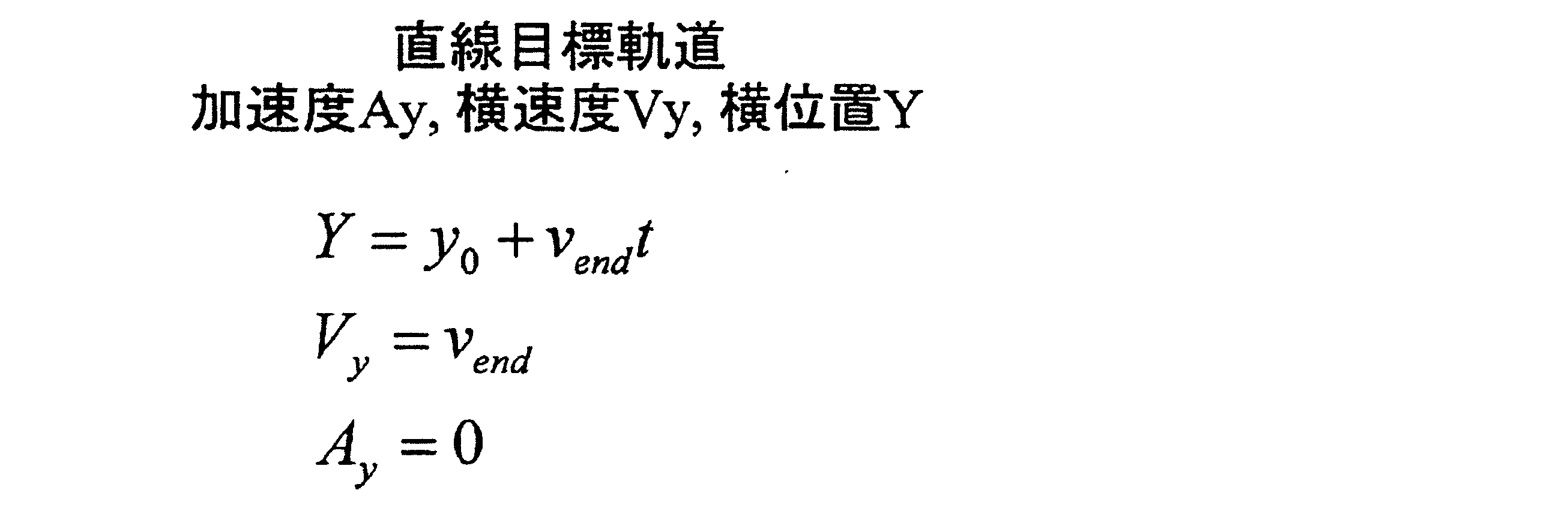
- the second target trajectory is obtained using a first-order polynomial with respect to time t as in the following equation.
- Ay is acceleration (transverse acceleration)
- Vy is lateral velocity (lateral velocity)
- Y is lateral position (lateral position).
- the lateral speed Vend is calculated according to the curvature of the lane in which the vehicle travels.
- the second target trajectory is a straight trajectory. In this way, the initial condition and the termination condition are reset, and the target trajectory is recalculated. Thereafter, this process is terminated.
- step S280 the arithmetic unit 10 calculates the second target trajectory in response to the fact that the straight trajectory flag is not ON.
- the second target trajectory is obtained by using a fifth-order polynomial for time t as shown in the following equation.
- Ay is acceleration (transverse acceleration)
- Vy is lateral velocity (lateral velocity)
- Y is lateral position (lateral position).
- Coefficients C1 to C6 are derived by setting initial conditions and termination conditions in each equation. Note that the current position of the vehicle is set as the initial condition (start condition), and the center of the lane is set as the termination condition. The center of the lane is the target point. In this way, the initial condition and the termination condition are reset, and the target trajectory is recalculated. Note that the target trajectory may be calculated using a 6th-order or higher polynomial instead of the 5th-order polynomial. Thereafter, this process is terminated.
- step S240 is executed by the target track calculation unit 111 in the calculation unit 10
- step S250 is executed by the traveling state determination unit 112
- steps S260, S270, and S280 are executed by the target track recalculation unit. 113.
- FIG. 4A is an explanatory diagram showing the lane departure suppression process (3)
- FIG. 4B is a flowchart showing the lane departure suppression process (3).
- step S310 the calculation unit 10 determines whether or not the vehicle departs from the lane. Since this process is the same as step S110 of the lane departure suppression process (1), detailed description is omitted here. If it is determined in step S310 that the vehicle does not depart from the lane within the reference time, the calculation unit 10 executes step S310 again. On the other hand, when it is determined in step S310 that the vehicle departs from the lane within the reference time, the process flow proceeds to step S320.
- step S320 the arithmetic unit 10 determines whether there is an operation by the driver. Since this process is the same as step S120 of the lane departure suppression process (1), detailed description is omitted here. If there is an operation by the driver in step S320, the process flow proceeds to step S310. On the other hand, if there is no operation by the driver in step S320, the flow of processing moves to step S330.
- step S330 the arithmetic unit 10 acquires the vehicle state at the control start point. Since this process is the same as step S130 of the lane departure suppression process (1), detailed description is omitted here. Thereafter, the process flow proceeds to step S340.
- step S340 the calculation unit 10 calculates a first target trajectory.
- the first target trajectory is obtained using a fifth-order polynomial with respect to time t as in the following equation.
- Ay is acceleration (transverse acceleration)
- Vy is lateral velocity (lateral velocity)
- Y is lateral position (lateral position).
- Coefficients C1 to C6 are derived by setting initial conditions and termination conditions in each equation.
- the current vehicle state is set as the initial condition
- the maximum deviation position Y1 is set as the termination condition.
- the maximum departure position Y1 is a point most deviating from the lane in which the vehicle is traveling.
- the maximum deviation position Y1 is the target point.
- the target trajectory may be calculated using a 6th-order or higher polynomial instead of the 5th-order polynomial. Thereafter, the process flow proceeds to step S350.
- step S350 the arithmetic unit 10 determines whether or not the lateral speed of the vehicle has turned inward.
- the arithmetic unit 10 determines whether or not the lateral speed of the vehicle has turned inward.
- the calculation unit 10 determines that it is not necessary to recalculate the target trajectory, and the calculation unit 10 executes step S350 again.
- step S350 when it is determined in step S350 that the lateral speed of the vehicle is directed inward, the calculation unit 10 determines that the target trajectory needs to be recalculated, and the process flow proceeds to step S360.
- step S350 the calculation unit 10 determines that the target track needs to be recalculated even when there is an obstacle in a direction in which the vehicle traveling along the target track deviates from the lane, and the processing is performed. The flow proceeds to step S360.
- a second target trajectory is calculated.
- the second target trajectory is obtained using a fifth-order polynomial with respect to time t as in the above equation.
- Ay is acceleration (transverse acceleration)
- Vy is lateral velocity (lateral velocity)
- Y is lateral position (lateral position).
- Coefficients C1 to C6 are derived by setting initial conditions and termination conditions as shown in the following expressions in each expression.
- the initial condition is a condition set at the start of control.
- the termination condition is a condition set at the end of control, and the point where the vehicle is located at the end of control is the target point.
- step S350 If it is determined in step S350 that the target track needs to be recalculated due to the presence of an obstacle, the distance from the lane in which the vehicle is traveling to the maximum departure point in the orthogonal direction is changed. By doing this, the control end point as the target point is reset. In this way, the initial condition and the termination condition are reset, and the target trajectory is recalculated. Note that the target trajectory may be calculated using a 6th-order or higher polynomial instead of the 5th-order polynomial. Thereafter, this process is terminated.
- step S340 is executed by the target track calculation unit 111 in the calculation unit 10
- step S350 is executed by the traveling state determination unit 112
- step S360 is executed by the target track recalculation unit 113.
- FIG. 5A is an explanatory diagram showing the lane departure suppression process (4)
- FIG. 5B is a flowchart showing the lane departure suppression process (4).
- step S410 the calculation unit 10 determines whether or not the vehicle departs from the lane. Since this process is the same as step S110 of the lane departure suppression process (1), detailed description is omitted here. If it is determined in step S410 that the vehicle does not depart from the lane within the reference time, the calculation unit 10 executes step S410 again. On the other hand, if it is determined in step S410 that the vehicle departs from the lane within the reference time, the process flow moves to step S420.
- step S420 it is determined whether or not there is an operation by the driver. Since this process is the same as step S120 of the lane departure suppression process (1), detailed description is omitted here. If there is an operation by the driver in step S420, the flow of processing moves to step S410. On the other hand, if there is no operation by the driver in step S420, the flow of processing moves to step S430.
- step S430 the arithmetic unit 10 acquires the vehicle state at the control start point. Since this process is the same as step S130 of the lane departure suppression process (1), detailed description is omitted here. Thereafter, the process flow proceeds to step S440.
- step S440 the calculation unit 10 calculates a first target trajectory.
- the first target trajectory is obtained using a fifth-order polynomial with respect to time t as in the following equation.
- Ay is acceleration (transverse acceleration)
- Vy is lateral velocity (lateral velocity)
- Y is lateral position (lateral position).
- Coefficients C1 to C6 are derived by setting initial conditions and termination conditions in each equation.
- the initial condition is a condition set at the start of control.
- the termination condition is a condition set at the end of control, and the point where the vehicle is located at the end of control is the target point. In the termination condition, it is possible to set the maximum deviation position Y1.
- the target trajectory may be calculated using a 6th-order or higher polynomial instead of the 5th-order polynomial. Thereafter, the process flow proceeds to step S450.
- step S450 the calculation unit 10 determines whether the error between the vehicle track and the target track is equal to or greater than Ydif. Specifically, the arithmetic unit 10 determines whether or not the distance between the track on which the vehicle travels in the orthogonal direction orthogonal to the lane extending direction and the target track is equal to or greater than a threshold (Ydif). If it is determined in step S450 that the error between the vehicle track and the target track is not Ydif or more, the calculation unit 10 determines that there is no need to recalculate the target track, and the calculation unit 10 again performs step S450. Execute.
- step S450 determines that the error between the vehicle trajectory and the target trajectory is greater than or equal to Ydif.
- the arithmetic unit 10 determines that the target trajectory needs to be recalculated, and the processing flow is step. The process proceeds to S460.
- step S460 the calculation unit 10 calculates a second target trajectory.
- the second target trajectory is obtained by using a fifth-order polynomial for time t as shown in the following equation.
- Ay is acceleration (transverse acceleration)
- Vy is lateral velocity (lateral velocity)
- Y is lateral position (lateral position).
- Coefficients C1 to C6 are derived by setting initial conditions and termination conditions as shown in the following expressions in each expression.
- the initial condition is a condition set at the start of control.
- the termination condition is a condition set at the end of control, and the point where the vehicle is located at the end of control is the target point. In this way, the initial condition and the termination condition are reset, and the target trajectory is recalculated.
- the target trajectory may be calculated using a 6th-order or higher polynomial instead of the 5th-order polynomial. Thereafter, this process is terminated.
- step S440 is executed by the target track calculation unit 111 in the calculation unit 10
- step S450 is executed by the traveling state determination unit 112
- step S460 is executed by the target track recalculation unit 113.
- FIG. 6A is an explanatory diagram showing the lane departure suppression process (5)
- FIG. 6B is a flowchart showing the lane departure suppression process (5).
- step S510 the arithmetic unit 10 determines whether or not the vehicle has returned to the inside from the target point. Since this process is the same as step S250 of the lane departure suppression process (2), detailed description is omitted here. If it is determined in step S510 that the vehicle has not returned to the inside of the target point, the calculation unit 10 determines that there is no need to recalculate the target trajectory, and the calculation unit 10 executes step S510 again. To do. On the other hand, when it is determined in step S510 that the vehicle has returned to the inside from the target point, the calculation unit 10 determines that it is necessary to recalculate the target trajectory, and the process flow proceeds to step S520. .
- step S520 the vehicle state at the control start point is acquired. Since this process is the same as step S130 of the lane departure suppression process (1), detailed description is omitted here. Thereafter, the process flow proceeds to step S530.
- step S530 the calculation unit 10 calculates the lateral speed.
- a value corresponding to the curvature of the lane in which the vehicle travels is selected with reference to the lateral speed setting MAP as shown in FIG.
- the curvature of the lane is calculated based on the detected coordinates of the left and right white lines. For example, when the curvature of the lane in which the vehicle travels is a value between R1 (negative value) and R2 (positive value), the lateral speed Vend is set to V1 (positive value) and the vehicle travels. For example, when the curvature of the lane is smaller than R1 (negative value) or larger than R2 (positive value), the lateral speed Vend is set to a numerical value 0. Thereafter, the process flow proceeds to step S540.
- step S540 the calculation unit 10 calculates a target trajectory.
- the target trajectory is obtained using a first-order polynomial with respect to time t as in the following equation.
- Ay is acceleration (transverse acceleration)
- Vy is lateral velocity (lateral velocity)
- Y is lateral position (lateral position).
- the lateral speed Vend set in step S530 and the lateral position Y0 at the time of switching the trajectory are used.
- the target trajectory is a straight trajectory. Thereafter, this process is terminated.
- FIG. 7A is an explanatory diagram showing the lane departure suppression process (6)
- FIG. 7B is an explanatory diagram showing the lane departure suppression process (6)
- FIG. 7C is a lane departure suppression process. It is a flowchart which shows (6).
- step S610 it is determined whether or not the vehicle departs from the lane. Since this process is the same as step S110 of the lane departure suppression process (1), detailed description is omitted here.
- step S610 when it is determined that the vehicle does not depart from the lane within the reference time, the arithmetic unit 10 executes step S610 again. On the other hand, if it is determined in step S610 that the vehicle departs from the lane within the reference time, the process flow proceeds to step S620.
- step S620 the arithmetic unit 10 determines whether there is an operation by the driver. Since this process is the same as step S120 of the lane departure suppression process (1), detailed description is omitted here. If there is an operation by the driver in step S620, the process flow moves to step S610. On the other hand, if there is no operation by the driver in step S620, the flow of processing moves to step S630.
- step S630 the arithmetic unit 10 acquires the vehicle state at the control start point. Since this process is the same as step S130 of the lane departure suppression process (1), detailed description is omitted here. Thereafter, the process flow proceeds to step S640.
- step S640 the calculation unit 10 calculates a first target trajectory.
- the first target trajectory is obtained using a fifth-order polynomial with respect to time t as in the following equation.
- Ay is acceleration (transverse acceleration)
- Vy is lateral velocity (lateral velocity)
- Y is lateral position (lateral position).
- Coefficients C1 to C6 are derived by setting initial conditions and termination conditions in each equation.
- the initial condition is a condition set at the start of control.
- the termination condition is a condition set at the end of control, and the point where the vehicle is located at the end of control is the target point. In the termination condition, it is possible to set the maximum deviation position Y1.
- the target trajectory may be calculated using a 6th-order or higher polynomial instead of the 5th-order polynomial. Thereafter, the process flow proceeds to step S650.
- step S650 the arithmetic unit 10 determines whether a person / obstacle has been found. Here, if there are people or obstacles in front of the vehicle traveling along the target track, it is determined that a person / obstacle has been found, and the person or obstacle ahead of the vehicle traveling along the target track. It is determined that no person / obstacle is found when there is no such thing. If it is determined in step S650 that no person / obstacle is found, the arithmetic unit 10 executes step S650 again. On the other hand, if it is determined in step S650 that a person / obstacle has been found, the process flow proceeds to step S660.
- step S660 the calculation unit 10 performs contact determination on the target trajectory.
- the calculation unit 10 determines whether or not the vehicle traveling along the target track comes into contact with the front obstacle found in step S650. If it is determined in step S660 that the vehicle traveling along the target track does not come into contact with an obstacle ahead as a result of the contact determination on the target track, the arithmetic unit 10 needs to recalculate the target track. If it is determined that there is not, the process flow proceeds to step S650. On the other hand, if it is determined in step S660 that the vehicle traveling along the target track is in contact with an obstacle ahead as a result of the contact determination on the target track, the arithmetic unit 10 needs to recalculate the target track. Therefore, the process flow proceeds to step S670.
- step S670 the calculation unit 10 recalculates the target trajectory.
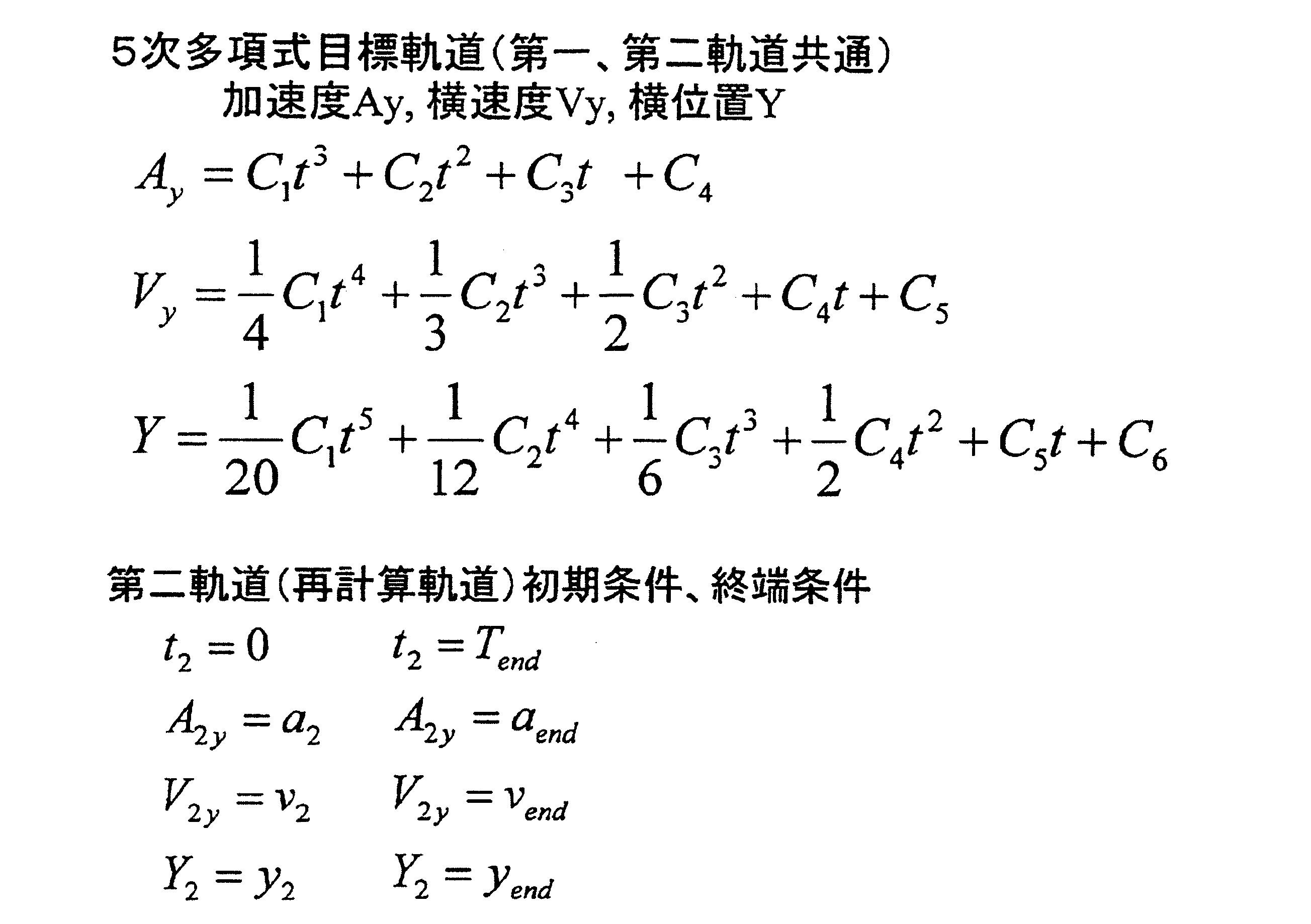
- the target trajectory is obtained using a fifth-order polynomial with respect to time t as in the following equation.
- Ay is acceleration (transverse acceleration)
- Vy is lateral velocity (lateral velocity)
- Y is lateral position (lateral position).
- Coefficients C1 to C6 are derived by setting initial conditions and termination conditions as shown in the following expressions in each expression.
- the initial condition is a condition set at the start of control.
- the termination condition is a condition that is set at the end of control, and a point at which the vehicle does not contact an obstacle is set as the end of control.
- the point where the vehicle is located at the end of control is the target point.
- the initial condition and the termination condition are reset, and the target trajectory is recalculated.
- the target trajectory may be calculated using a 6th-order or higher polynomial instead of the 5th-order polynomial. Thereafter, this process is terminated.
- step S640 is executed by the target track calculation unit 111 in the calculation unit 10
- steps S650 and S660 are executed by the traveling state determination unit 112
- step S670 is executed by the target track recalculation unit 113. Executed.
- FIG. 8A is an explanatory diagram showing the lane departure suppression process (7)
- FIG. 8B is an explanatory diagram showing the lane departure suppression process (7)
- FIG. 8C is a lane departure suppression process. It is a flowchart which shows (7).
- step S710 the calculation unit 10 determines whether or not the vehicle departs from the lane. Since this process is the same as S110 of the lane departure suppression process (1), a detailed description is omitted here. If it is determined in step S710 that the vehicle does not depart from the lane within the reference time, the calculation unit 10 executes step S710 again. On the other hand, when it is determined in step S710 that the vehicle departs from the lane within the reference time, the process flow proceeds to step S720.
- step S720 the arithmetic unit 10 determines whether there is an operation by the driver. Since this process is the same as step S120 of the lane departure suppression process (1), detailed description is omitted here. If there is an operation by the driver in step S720, the flow of processing moves to step S710. On the other hand, if there is no operation by the driver in step S720, the flow of processing moves to step S730.
- step S730 the calculation unit 10 acquires the vehicle state at the control start point. Since this process is the same as step S130 of the lane departure suppression process (1), detailed description is omitted here. Thereafter, the process flow proceeds to step S740.
- step S740 the calculation unit 10 calculates a target trajectory.
- the target trajectory is obtained using a fifth-order polynomial with respect to time t as in the following equation.
- Ay is acceleration (transverse acceleration)
- Vy is lateral velocity (lateral velocity)
- Y is lateral position (lateral position).
- Coefficients C1 to C6 are derived by setting initial conditions and termination conditions in each equation.
- the initial condition is a condition set at the start of control.
- the termination condition is a condition set at the end of control, and the point where the vehicle is located at the end of control is the target point.
- an optimum value is calculated so that the steering behavior or the deviation amount is within the target value.
- the target trajectory may be calculated using a 6th-order or higher polynomial instead of the 5th-order polynomial. Thereafter, the process flow proceeds to step S750.
- step S750 the calculation unit 10 determines whether or not the torque change rate or the steering angle change rate has exceeded the set threshold value ⁇ .
- the steering control apparatus contained in the control object apparatus 30 detects from a steering mechanism.
- the set threshold value ⁇ is set in advance by experiments or the like from the viewpoint of preventing steep steering behavior. Therefore, when the rate of change in torque or the rate of change in rudder angle exceeds the set threshold value ⁇ , it is determined that the steering behavior of the vehicle exceeds the threshold value when traveling on the target track, and that there is a steep steering behavior.
- step S750 If it is determined in step S750 that the rate of change in torque or the rate of change in steering angle does not exceed the set threshold value ⁇ , it is determined that there is no steep steering behavior and there is no need to recalculate the target trajectory, This process ends. On the other hand, when it is determined in step S750 that the torque or the steering angle change rate has exceeded the set threshold ⁇ , the calculation unit 10 determines that there is a steep steering behavior and the target trajectory needs to be recalculated. The process flow proceeds to step S760.
- step S760 the calculation unit 10 outputs a torque or a steering angle with a threshold gradient. Specifically, a torque value or a steering angle value is output such that the torque change rate or the steering angle change rate is less than the set threshold value ⁇ . Thereafter, the process flow proceeds to step S770.
- step S770 the arithmetic unit 10 recalculates the target trajectory.
- the target trajectory is obtained using a fifth-order polynomial with respect to time t as in the following equation.
- Ay is acceleration (transverse acceleration)
- Vy is lateral velocity (lateral velocity)
- Y is lateral position (lateral position).
- Coefficients C1 to C6 are derived by setting initial conditions and termination conditions as shown in the following expressions in each expression.
- the initial condition is a condition set at the start of control.
- the termination condition is a condition set at the end of control, and the point where the vehicle is located at the end of control is the target point.
- the termination condition is set based on the torque value or the steering angle value output in step S760 from the viewpoint of preventing steep steering behavior.
- the initial condition and the termination condition are reset, and the target trajectory is recalculated.
- the target trajectory may be calculated using a 6th-order or higher polynomial instead of the 5th-order polynomial.
- a behavior suppressing operation for suppressing the steering behavior of the vehicle may be executed simultaneously with or instead of recalculating the target trajectory in step S770.
- the control target device 30 controls the steering mechanism to stop the execution of the deviation suppression operation, or the control target device 30 controls the drive mechanism or the braking mechanism to decelerate the vehicle.
- the information output device 40 may notify the driver using sound output by a buzzer or a speaker or display by a display device or a lamp. Thereafter, the process flow proceeds to step S750.
- step S740 is executed by the target track calculation unit 111 in the calculation unit 10
- step S750 is executed by the traveling state determination unit 112
- step S770 is executed by the target track recalculation unit 113.
- the target trajectory is recalculated according to the traveling state of the vehicle. It is possible to generate a target trajectory that can cope with the above.
Landscapes
- Engineering & Computer Science (AREA)
- Transportation (AREA)
- Mechanical Engineering (AREA)
- Chemical & Material Sciences (AREA)
- Combustion & Propulsion (AREA)
- Physics & Mathematics (AREA)
- Automation & Control Theory (AREA)
- Mathematical Physics (AREA)
- General Physics & Mathematics (AREA)
- Steering Control In Accordance With Driving Conditions (AREA)
- Traffic Control Systems (AREA)
- Control Of Driving Devices And Active Controlling Of Vehicle (AREA)
Abstract
車線逸脱抑制システム(1)は、車両が走行中の車線内の前方に目標地点を設定し、設定した目標地点まで車両を走行させる軌道を目標軌道として時間に対する5次の多項式を用いて算出する。その後、目標軌道に沿って走行する車両が車線の延伸方向に直交する直交方向において目標地点から離間した後に目標地点へ復帰した場合に、前記目標軌道を再算出する必要があると判断する。目標軌道を再算出する必要があると判断された場合に、目標軌道を再算出する。目標軌道を再算出するために、車両の走行状況に応じて、時間に対する5次以上の多項式または時間に対する1次の多項式を選択する。時間に対する1次の多項式を用いる場合には、直交方向において車両が移動する速度である横速度を算出して用いる。
Description
本出願は、2015年6月26日に出願された日本出願番号2015-128884号に基づくもので、ここにその記載内容を援用する。
本発明は、車両が車線から逸脱することを抑制する車線逸脱抑制システムに関する。
車両の自動運転に関しては、自車両の走行軌道を生成する処理や、自車両を走行軌道に沿って走行させるためのフィードフォワード制御およびフィードバック制御、自車両の車線からの逸脱を抑制する車線逸脱抑制制御など、様々な技術が提案されている(例えば、特許文献1~4参照)。
上述の車線逸脱抑制制御においては、自車両のトルク出力の安定性とフィードバック制御によるロバスト性とを両立させることが求められる。そのためには、目標軌道を生成するとともに、生成した目標軌道に沿って自車両を走行させるためにフィードフォワード制御およびフィードバック制御を組み合わせる必要があった。このような場合、様々な車両逸脱状況に対応した目標軌道を生成することが重要となるが、そのための技術については上記特許文献1~4には開示されていない。
本発明は、上記に鑑みなされたものであり、その目的とするところは、様々な車両逸脱状況にも対応可能な目標軌道を生成する技術を提供することにある。
本発明の一態様による車線逸脱抑制システムによれば、目標地点まで車両を走行させる軌道である目標軌道を算出した後に、例えば、次の(1)~(5)のように、車両の走行状況に応じて目標軌道を再算出する。なお、目標地点までの目標軌道については、時間に対する5次以上の多項式を用いて算出される。
(1)目標軌道に沿って走行する車両が車線の延伸方向に直交する直交方向において目標地点から離間した後に目標地点に復帰した場合には、目標地点を再設定してその目標地点までの目標軌道を算出する。
(2)目標軌道に沿って走行する車両が直交方向において車線から逸脱した後に車線へ向けて移動し始めた場合には、目標地点を再設定してその目標地点までの目標軌道を算出する。
(3)直交方向における車両が走行する軌道と目標軌道との間の距離が閾値以上になった場合には、目標地点を再設定してその目標地点までの目標軌道を算出する。
(4)目標軌道に沿って走行する車両が障害物と接触する場合には、車両が障害物と接触しない地点を目標地点に再設定してその目標地点までの目標軌道を算出する。
(5)目標軌道に沿って走行する車両のステアリング挙動が閾値を超える場合には、目標地点を再設定して、その目標地点までの目標軌道を走行中には車両のステアリング挙動が閾値を超えないように目標軌道を算出する。
なお、上記(1)においては、目標軌道を再算出するために、車両の走行状況に応じて、時間に対する5次以上の多項式または時間に対する1次の多項式を選択するようにしてもよい。時間に対する1次の多項式を用いる場合には、直交方向において車両が移動する速度である横速度を算出して用いてもよい。また、横速度については、車線の曲率に応じて算出するようにしてもよい。
また、上記(2)においては、障害物が存在する場合には、目標軌道に沿って走行する車両が直交方向において車線から最も逸脱する最大逸脱量を変更することで目標地点を再設定するようにしてもよい。
また、上記(5)においては、目標軌道の再算出と同時か目標軌道の再算出の代わりに、車両のステアリング挙動を抑制するための挙動抑制動作を実行するようにしてもよい。例えば、車両が車線から逸脱することを抑制する逸脱抑制動作を中止させることや、車両を減速させること、ステアリング挙動が閾値を超える旨をドライバに報知することなどである。
したがって、本発明の車線逸脱抑制システムによれば、様々な車両逸脱状況にも対応可能な目標軌道を生成することができる。
以下、本発明の実施形態を、添付図面を参照しながら、より詳細に説明する。しかし、本発明は、多くの異なる形態で実施されてもよく、本明細書で説明される実施形態に限定されると解釈されるべきではない。むしろ、これらの実施形態は、この発明の開示を徹底的でかつ完全にし、本発明の範囲を当業者に完全に伝えるために、提供される。尚、類似の符号は、図面全体にわたって類似の構成要素を示す。
(1.車線逸脱抑制システムの構成の説明)
図1Aに示す車線逸脱抑制システム1は、例えば、乗用車等の車両に搭載され、該自車両が走行中の車線を逸脱することを抑制する制御を行うシステムである。なお、ここで言う車線とは、左右の白線(実車線)内の領域である走行領域である。また、ここでは、車線逸脱抑制システム1を搭載している車両を自車両と呼ぶ。
図1Aに示す車線逸脱抑制システム1は、例えば、乗用車等の車両に搭載され、該自車両が走行中の車線を逸脱することを抑制する制御を行うシステムである。なお、ここで言う車線とは、左右の白線(実車線)内の領域である走行領域である。また、ここでは、車線逸脱抑制システム1を搭載している車両を自車両と呼ぶ。
具体的には、車線逸脱抑制システム1は、演算部10と、カメラ20と、車速センサ21と、ヨーレートセンサ22と、舵角センサ23と、制御対象装置30と、情報出力装置40と、を備えている。
演算部10は、CPU、ROM、RAM等を備えた周知のマイコンとして構成されており、ROMに格納されたプログラム等に従って、車両が走行中の車線から逸脱することを抑制する車線逸脱抑制処理などの各種処理を実行する。車線逸脱抑制処理については後述する。また、演算部10は、車線逸脱抑制処理によって生成された目標軌道に沿って車両を走行させるための制御指令を生成して制御対象装置30に送信する。
なお、演算部10は、図1Bに示すように機能ブロックとして、自車両を走行させる目標軌道を生成する目標軌道生成部101と、目標軌道生成部101によって生成された目標軌道に沿って自車両を走行させるための制御指令を生成して送信する制御指令送信部102とを有する。また、目標軌道生成部101は、目標軌道算出部111、走行状況判断部112、および目標軌道再算出部113を有する。これらの機能ブロックの働きについては、後述する車線逸脱抑制処理(1)-(7)の説明の中で言及する。
カメラ20は、自車両の進行方向の路面を撮像し、周知の白線認識の技術を用いて、白線と自車両の進行方向とのなす角を表す逸脱角度、白線までの距離、カーブ半径等を検出し、これらの情報を撮像情報として演算部10に送る。なお、カメラ20が撮像画像を得る機能のみを備えている場合には、演算部10が撮像画像に基づいて撮像情報を演算するようにしてもよい。
車速センサ21は、自車両の走行速度を検出する周知の車速センサとして構成されており、走行速度の検出結果を演算部10に送る。また、ヨーレートセンサ22は、自車両の旋回方向への回転角速度を検出する周知のヨーレートセンサとして構成されており、ヨーレートの検出結果を演算部10に送る。また、舵角センサ23は、車両の舵角を検出する周知の舵角センサとして構成されており、舵角の検出結果を演算部10に送る。
制御対象装置30は、演算部10が制御する被制御装置であり、演算部10、詳しくは上記制御指令送信部102、から送信された制御指令に基づき、車両が走行中の車線から逸脱することを抑制する動作である逸脱抑制動作を実行する逸脱抑制動作部として機能する。本実施形態における被制御装置には、ステアリング機構を制御するステアリング制御装置と、駆動機構を制御する駆動制御装置と、制動機構を制御する制動制御装置と、を含む。ここでの駆動機構には、自車両の駆動力を発生する駆動力発生装置(例えば、内燃機関やモータ)と、その駆動力を伝達する伝達系(例えば、トランスミッションなど)とを含む。制御対象装置30は更に、例えば、ステアリング機構を制御することにより逸脱抑制動作の実行を中止させることや、駆動機構または制動機構を制御することにより車両を減速させるといった挙動抑制動作を実行する挙動抑制動作部の一部としての機能も有する。
情報出力装置40は、演算部10からの情報を報知する周知の装置である。この情報出力装置40には、情報を表示する表示装置と、情報を音声によって出力する音声出力装置と、を含む。後述するように、情報出力装置40は、挙動抑制動作を実行する挙動抑制動作部の一部としての機能を有する。
(2.車線逸脱抑制処理の説明)
次に、車線逸脱抑制システム1の演算部10が実行する車線逸脱抑制処理(1)~(7)について説明する。
次に、車線逸脱抑制システム1の演算部10が実行する車線逸脱抑制処理(1)~(7)について説明する。
車線逸脱抑制処理は、車両が走行中の車線から逸脱することを抑制する処理であり、例えば車線逸脱抑制システム1の電源が投入されると開始され、その後、一定時間毎(例えば50ms毎)に繰り返し実行される。
(2.1.車線逸脱抑制処理(1)の説明)
まず、車線逸脱抑制処理(1)を、図2を参照して説明する。図2(a)は車線逸脱抑制処理(1)を示す説明図であり、図2(b)は車線逸脱抑制処理(1)を示すフローチャートである。
まず、車線逸脱抑制処理(1)を、図2を参照して説明する。図2(a)は車線逸脱抑制処理(1)を示す説明図であり、図2(b)は車線逸脱抑制処理(1)を示すフローチャートである。
最初のステップS110では、演算部10は、車両が車線逸脱するか否かを判断する。具体的には、基準となる時間(例えば2秒間)以内に車両が車線(走行領域)を逸脱するか否かを判定する。この処理では、撮像情報として得られた逸脱角度、実車線までの距離、および自車両の走行速度に基づいて、自車両が実車線に到達するまでの時間を演算し、この時間が基準となる時間以内となるか否かを判定する。ステップ110において、基準となる時間以内に車両が車線を逸脱しないと判断された場合には、演算部10は再度ステップS110を実行する。一方、ステップ110において、基準となる時間以内に車両が車線を逸脱すると判断された場合には、処理の流れはステップS120に移行する。
ステップS120では、ドライバによる操作があるか否かを判定する。ここで、ドライバによる操作とは、ステアリングを接近している実車線から遠ざかる方向に変更する操作を示し、舵角センサ23による検出結果を繰り返し監視することでこの操作の有無を検出する。
ステップS120において、ドライバによる操作があれば、処理の流れはステップS110に移行する。一方、ステップS120において、ドライバによる操作がなければ、処理の流れはステップS130に移行する。
ステップS130では、演算部10は、制御開始地点での車両状態を取得する。具体的には、撮像情報として得られた逸脱角度、実車線までの距離、および自車両の走行速度に基づいて自車両の横方向の位置および横方向の速度を算出するとともに、自車両の走行速度を車速センサ21から取得し、ヨーレートをヨーレートセンサ22から取得する。その後、処理の流れはステップS140に移行する。
ステップS140では、演算部10は、目標軌道を算出する。目標軌道は、次式のような時間tに対する5次の多項式を用いて得られる。Ayは加速度(横方向の加速度)、Vyは横速度(横方向の速度)、Yは横位置(横方向の位置)である。各式に初期条件および終端条件を設定することで、係数C1~C6を導出する。初期条件は、制御開始時点で設定される条件である。また、終端条件は、制御終了時点で設定される条件であり、制御終了時点に車両が位置する地点が目標地点となる。時間Tendについては、ステアリング挙動または逸脱量が目標値以内となる最適値を算出する。なお、5次の多項式の代わりに、6次以上の多項式を用いて目標軌道を算出してもよい。その後、本処理を終了する。
車線逸脱抑制処理(1)において、ステップS140は演算部10内の目標軌道算出部111によって実行される

(2.2.車線逸脱抑制処理(2)の説明)
次に、車線逸脱抑制処理(2)を、図3を参照して説明する。図3(a)は車線逸脱抑制処理(2)を示す説明図であり、図3(b)は車線逸脱抑制処理(2)を示すフローチャートである。
次に、車線逸脱抑制処理(2)を、図3を参照して説明する。図3(a)は車線逸脱抑制処理(2)を示す説明図であり、図3(b)は車線逸脱抑制処理(2)を示すフローチャートである。
最初のステップS210では、演算部10は、車両が車線逸脱するか否かを判断する。この処理は、車線逸脱抑制処理(1)のステップS110と同様であるので、ここでは詳細な説明は省略する。ステップS210において、基準となる時間以内に車両が車線を逸脱しないと判断された場合には、演算部10は再度ステップS210を実行する。一方、ステップS210において、基準となる時間以内に車両が車線を逸脱すると判断された場合には、処理の流れはステップS220に移行する。
ステップS220では、演算部10は、ドライバによる操作があるか否かを判定する。この処理は、車線逸脱抑制処理(1)のS120と同様であるので、ここでは詳細な説明は省略する。ステップS220において、ドライバによる操作があれば、処理の流れはステップS210に移行する。一方、ステップS220において、ドライバによる操作がなければ、処理の流れはステップS230に移行する。
ステップS230では、演算部10は、制御開始地点での車両状態を取得する。この処理は、車線逸脱抑制処理(1)のステップS130と同様であるので、ここでは詳細な説明は省略する。また、本ステップS230では、演算部10は、車両が走行する車線の曲率を車両状態として取得する。その後、処理の流れはステップS240に移行する。
ステップS240では、演算部10は、第一の目標軌道を算出する。第一の目標軌道は、次式のような時間tに対する5次の多項式を用いて得られる。Ayは加速度(横方向の加速度)、Vyは横速度(横方向の速度)、Yは横位置(横方向の位置)である。各式に初期条件および終端条件を設定することで、係数C1~C6を導出する。初期条件は、制御開始時点で設定される条件である。また、終端条件は、制御終了時点で設定される条件であり、制御終了時点に車両が位置する地点が目標地点となる。時間Tendについては、ステアリング挙動または逸脱量が目標値以内となる最適値を算出する。なお、5次の多項式の代わりに、6次以上の多項式を用いて目標軌道を算出してもよい。その後、処理の流れはステップS250に移行する。

ステップS250では、演算部10は、車両が目標地点より内側に復帰したか否かを判断する。ここでは、演算部10は、目標軌道に沿って走行する車両が車線の延伸方向に直交する直交方向において目標地点から離間した後に目標地点へ復帰した場合に、車両が目標地点より内側に復帰したと判断する。ステップS250において、車両が目標地点より内側に復帰していないと判断された場合には、目標軌道を再算出する必要がないと判断し、演算部10は、再度ステップS250を実行する。一方、ステップS250において、車両が目標地点より内側に復帰したと判断された場合には、目標軌道を再算出する必要があると判断し、処理の流れはステップS260に移行する。
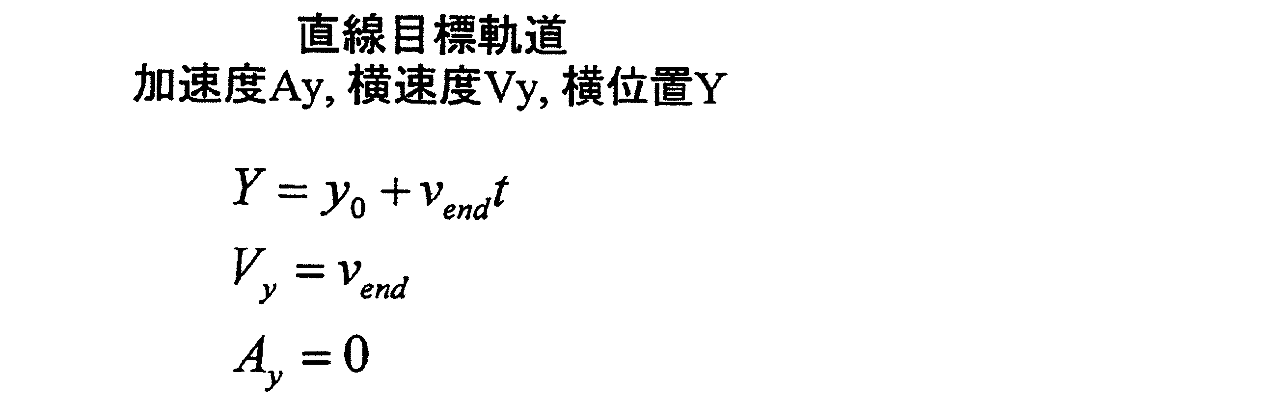
ステップS260では、演算部10は、直線軌道フラグがONであるか否かを判断する。なお、直線軌道フラグは、車両の走行状況に応じてON/OFFの切り替えが可能である。直線軌道フラグがONである場合には、再計算後の目標軌道として直線軌道が適切であることを示し、直線軌道フラグがOFFである場合には、再計算後の目標軌道として直線軌道が適切ではないことを示す。ステップS260において、直線軌道フラグがONである場合には、処理の流れはステップS270に移行する。一方、ステップS260において、直線軌道フラグがONではない場合には、処理の流れはステップS280に移行する。
ステップS270では、演算部10は、直線軌道フラグがONであることを受けて第二の目標軌道を算出する。第二の目標軌道は、次式のような時間tに対する1次の多項式を用いて得られる。Ayは加速度(横方向の加速度)、Vyは横速度(横方向の速度)、Yは横位置(横方向の位置)である。なお、初期条件には、横速度Vendおよび軌道を切り替える時点での横位置Y0を用いる。横速度Vendについては、車両が走行する車線の曲率に応じて算出する。この結果、第二の目標軌道は、直線軌道となる。このように初期条件および終端条件が再設定され、目標軌道が再算出される。その後、本処理を終了する。
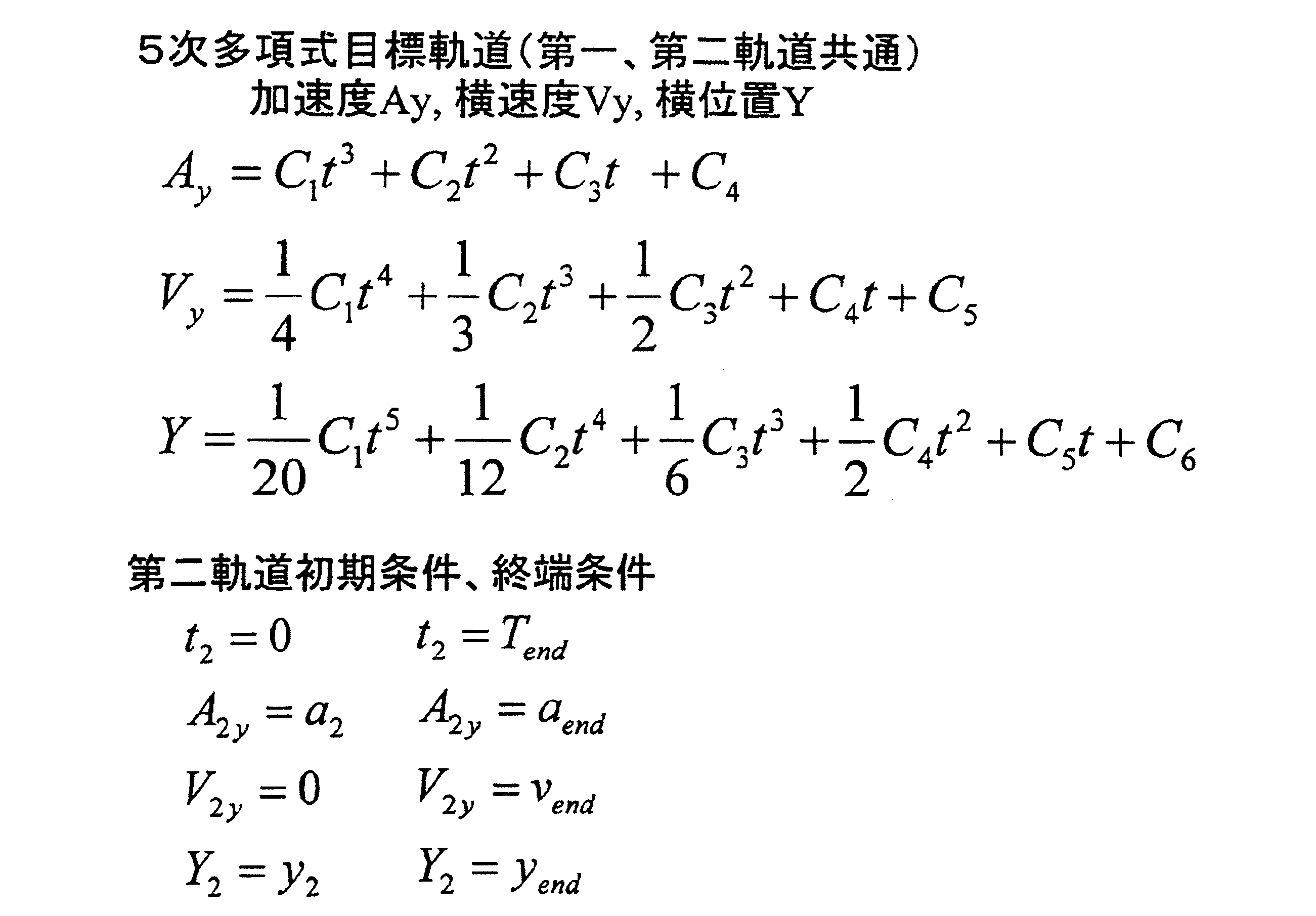
ステップS280では、演算部10は、直線軌道フラグがONではないことを受けて第二の目標軌道を算出する。第二の目標軌道は、次式のような時間tに対する5次の多項式を用いて得られる。Ayは加速度(横方向の加速度)、Vyは横速度(横方向の速度)、Yは横位置(横方向の位置)である。各式に初期条件および終端条件を設定することで、係数C1~C6を導出する。なお、初期条件(開始条件)には車両の現在位置を設定し、終端条件には車線中央を設定する。車線中央は目標地点である。このように初期条件および終端条件が再設定され、目標軌道が再算出される。なお、5次の多項式の代わりに、6次以上の多項式を用いて目標軌道を算出してもよい。その後、本処理を終了する。
車線逸脱抑制処理(2)において、ステップS240は演算部10内の目標軌道算出部111によって実行され、ステップS250は走行状況判断部112によって実行され、ステップS260、S270、S280は目標軌道再算出部113によって実行される。

(2.3.車線逸脱抑制処理(3)の説明)
次に、車線逸脱抑制処理(3)を、図4を参照して説明する。図4(a)は車線逸脱抑制処理(3)を示す説明図であり、図4(b)は車線逸脱抑制処理(3)を示すフローチャートである。
次に、車線逸脱抑制処理(3)を、図4を参照して説明する。図4(a)は車線逸脱抑制処理(3)を示す説明図であり、図4(b)は車線逸脱抑制処理(3)を示すフローチャートである。
最初のステップS310では、演算部10は、車両が車線逸脱するか否かを判断する。この処理は、車線逸脱抑制処理(1)のステップS110と同様であるので、ここでは詳細な説明は省略する。ステップS310において、基準となる時間以内に車両が車線を逸脱しないと判断された場合には、演算部10は再度ステップS310を実行する。一方、ステップS310において、基準となる時間以内に車両が車線を逸脱すると判断された場合には、処理の流れはステップS320に移行する。
ステップS320では、演算部10は、ドライバによる操作があるか否かを判定する。この処理は、車線逸脱抑制処理(1)のステップS120と同様であるので、ここでは詳細な説明は省略する。ステップS320において、ドライバによる操作があれば、処理の流れはステップS310に移行する。一方、ステップS320において、ドライバによる操作がなければ、処理の流れはステップS330に移行する。
ステップS330では、演算部10は、制御開始地点での車両状態を取得する。この処理は、車線逸脱抑制処理(1)のステップS130と同様であるので、ここでは詳細な説明は省略する。その後、処理の流れはステップS340に移行する。
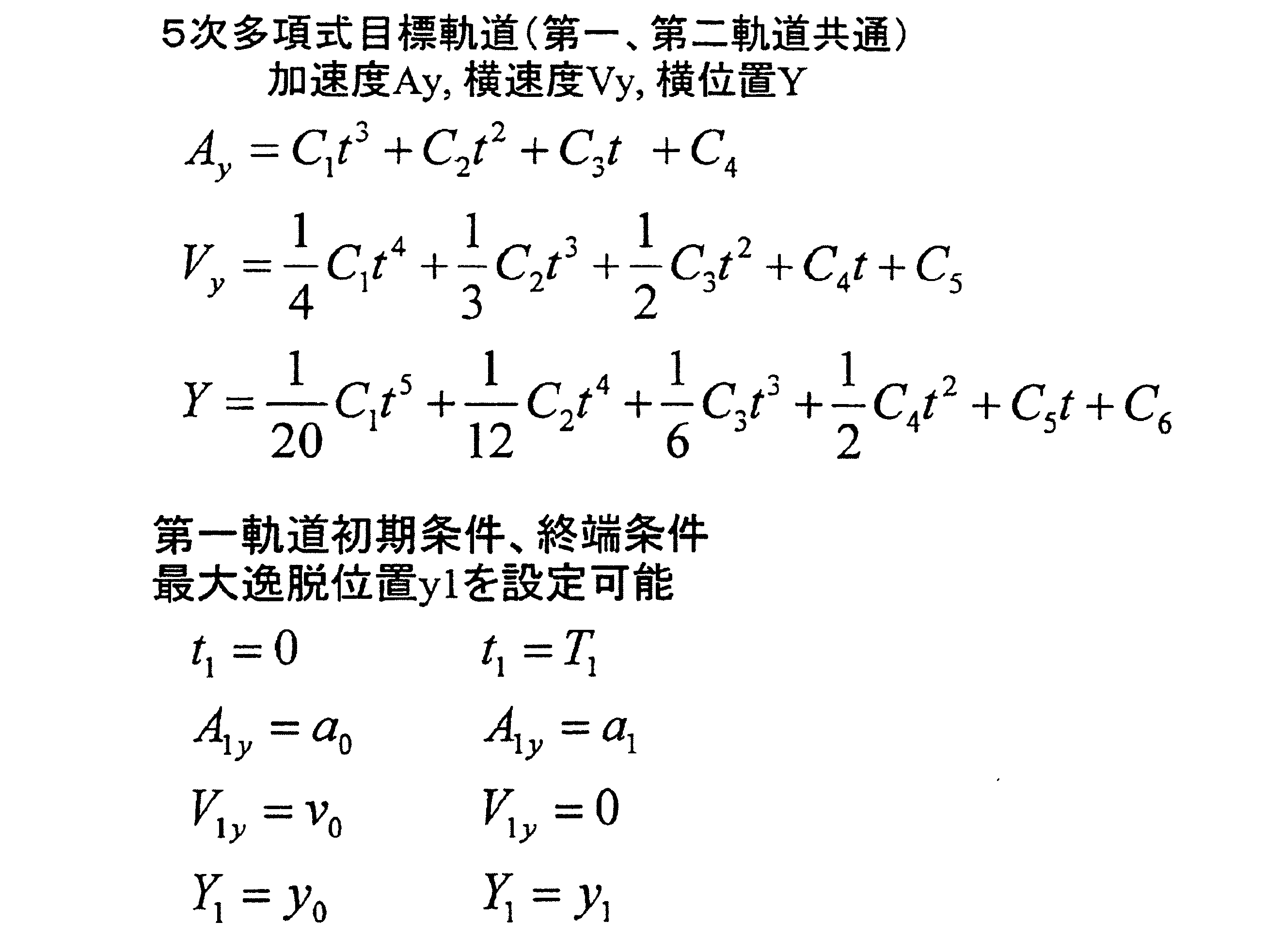
ステップS340では、演算部10は、第一の目標軌道を算出する。第一の目標軌道は、次式のような時間tに対する5次の多項式を用いて得られる。Ayは加速度(横方向の加速度)、Vyは横速度(横方向の速度)、Yは横位置(横方向の位置)である。各式に初期条件および終端条件を設定することで、係数C1~C6を導出する。初期条件には、現在の車両状態を設定し、終端条件には最大逸脱位置Y1を設定する。最大逸脱位置Y1は、車両が走行中の車線から最も逸脱する地点である。最大逸脱位置Y1が目標地点となる。なお、5次の多項式の代わりに、6次以上の多項式を用いて目標軌道を算出してもよい。その後、処理の流れはステップS350に移行する。
ステップS350では、演算部10は、車両の横速度が内側を向いたか否かを判断する。ここでは、目標軌道に沿って走行する車両が車線の延伸方向に直交する直交方向において車線から逸脱した後に車線へ向けて移動し始めた場合に、車両の横速度が内側を向いたと判断する。ステップS350において、車両の横速度が内側を向いていないと判断された場合には、演算部10は、目標軌道を再算出する必要がないと判断し、演算部10は再度ステップS350を実行する。一方、ステップS350において、車両の横速度が内側を向いたと判断された場合には、演算部10は、目標軌道を再算出する必要があると判断し、処理の流れはステップS360に移行する。なお、上記ステップS350において、演算部10は、目標軌道に沿って走行する車両が車線から逸脱する方向に障害物が存在する場合にも、目標軌道を再算出する必要があると判断し、処理の流れはステップS360に移行する。
ステップS360では、第二の目標軌道を算出する。第二の目標軌道は、上式のような時間tに対する5次の多項式を用いて得られる。Ayは加速度(横方向の加速度)、Vyは横速度(横方向の速度)、Yは横位置(横方向の位置)である。各式に次式のような初期条件および終端条件を設定することで、係数C1~C6を導出する。初期条件は、制御開始時点で設定される条件である。また、終端条件は、制御終了時点で設定される条件であり、制御終了時点に車両が位置する地点が目標地点となる。なお、上記ステップS350において、障害物の存在に起因して目標軌道を再算出する必要があると判断された場合には、直交方向における車両が走行中の車線から最大逸脱地点までの距離を変更することで目標地点としての制御終了時点を再設定する。このように初期条件および終端条件が再設定され、目標軌道が再算出される。なお、5次の多項式の代わりに、6次以上の多項式を用いて目標軌道
を算出してもよい。その後、本処理を終了する。
を算出してもよい。その後、本処理を終了する。
車線逸脱抑制処理(3)において、ステップS340は演算部10内の目標軌道算出部111によって実行され、ステップS350は走行状況判断部112によって実行され、ステップS360は目標軌道再算出部113によって実行される。
(2.4.車線逸脱抑制処理(4)の説明)
次に、車線逸脱抑制処理(4)を、図5を参照して説明する。図5(a)は車線逸脱抑制処理(4)を示す説明図であり、図5(b)は車線逸脱抑制処理(4)を示すフローチャートである。
次に、車線逸脱抑制処理(4)を、図5を参照して説明する。図5(a)は車線逸脱抑制処理(4)を示す説明図であり、図5(b)は車線逸脱抑制処理(4)を示すフローチャートである。
最初のステップS410では、演算部10は、車両が車線逸脱するか否かを判断する。この処理は、車線逸脱抑制処理(1)のステップS110と同様であるので、ここでは詳細な説明は省略する。ステップS410において、基準となる時間以内に車両が車線を逸脱しないと判断された場合には、演算部10は再度ステップS410を実行する。一方、ステップS410において、基準となる時間以内に車両が車線を逸脱すると判断された場合には、処理の流れはステップS420に移行する。
ステップS420では、ドライバによる操作があるか否かを判定する。この処理は、車線逸脱抑制処理(1)のステップS120と同様であるので、ここでは詳細な説明は省略する。ステップS420において、ドライバによる操作があれば、処理の流れはステップS410に移行する。一方、ステップS420において、ドライバによる操作がなければ、処理の流れはステップS430に移行する。
ステップS430では、演算部10は、制御開始地点での車両状態を取得する。この処理は、車線逸脱抑制処理(1)のステップS130と同様であるので、ここでは詳細な説明は省略する。その後、処理の流れはステップS440に移行する。
ステップS440では、演算部10は、第一の目標軌道を算出する。第一の目標軌道は、次式のような時間tに対する5次の多項式を用いて得られる。Ayは加速度(横方向の加速度)、Vyは横速度(横方向の速度)、Yは横位置(横方向の位置)である。各式に初期条件および終端条件を設定することで、係数C1~C6を導出する。初期条件は、制御開始時点で設定される条件である。また、終端条件は、制御終了時点で設定される条件であり、制御終了時点に車両が位置する地点が目標地点となる。終端条件では、最大逸脱位置Y1を設定することも可能である。なお、5次の多項式の代わりに、6次以上の多項式を用いて目標軌道を算出してもよい。その後、処理の流れはステップS450に移行する。
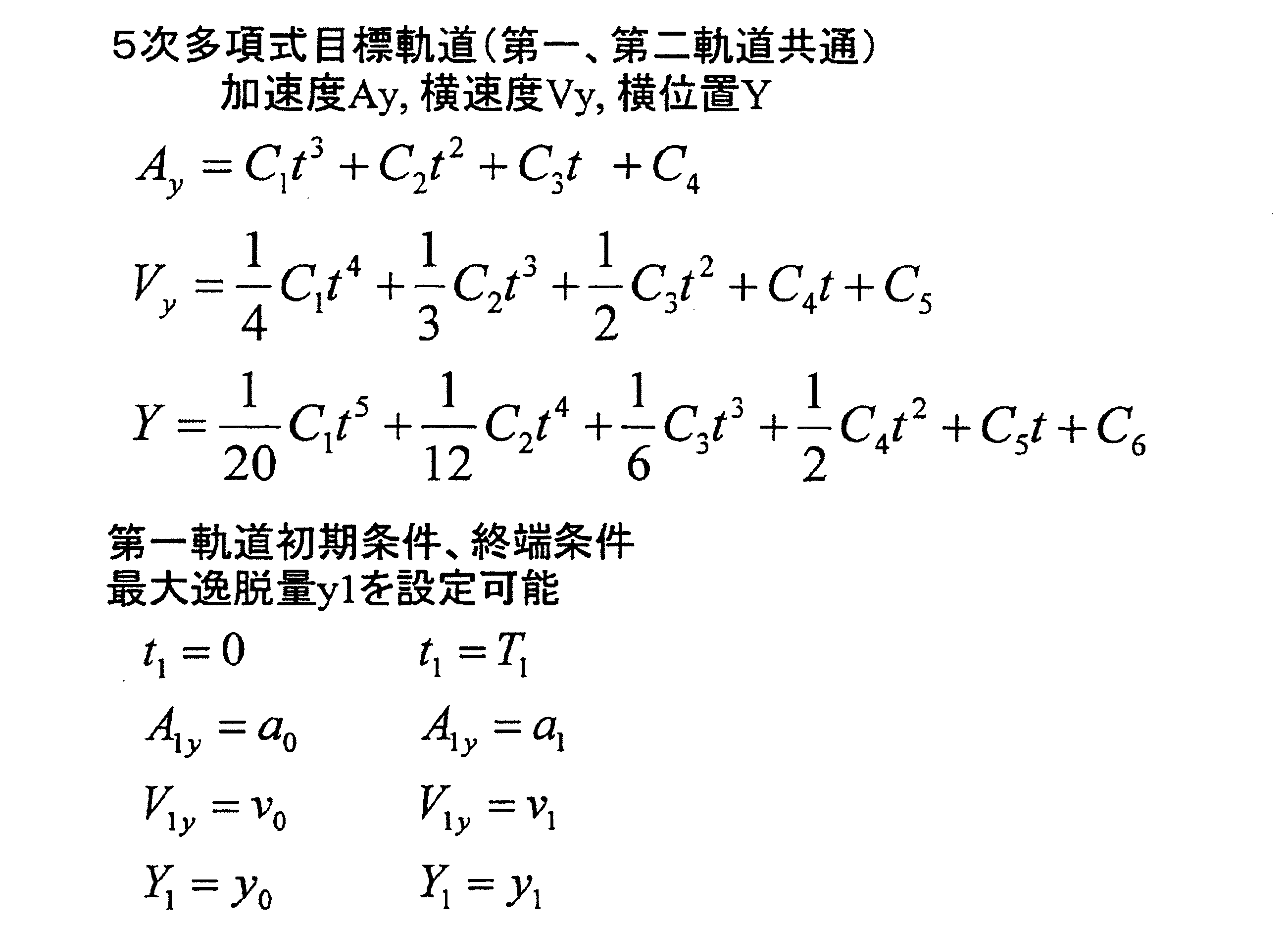
ステップS450では、演算部10は、車両軌道と目標軌道との誤差がYdif以上であるか否かを判断する。具体的には、演算部10は、車線の延伸方向に直交する直交方向における車両が走行する軌道と目標軌道との間の距離が閾値(Ydif)以上であるか否かを判断する。ステップS450において、車両軌道と目標軌道との誤差がYdif以上ではないと判断された場合には、演算部10は、目標軌道を再算出する必要がないと判断し、演算部10は再度ステップS450を実行する。一方、ステップS450において、車両軌道と目標軌道との誤差がYdif以上であると判断された場合には、演算部10は、目標軌道を再算出する必要があると判断し、処理の流れはステップS460に移行する。
ステップS460では、演算部10は、第二の目標軌道を算出する。第二の目標軌道は、次式のような時間tに対する5次の多項式を用いて得られる。Ayは加速度(横方向の加速度)、Vyは横速度(横方向の速度)、Yは横位置(横方向の位置)である。各式に次式のような初期条件および終端条件を設定することで、係数C1~C6を導出する。初期条件は、制御開始時点で設定される条件である。また、終端条件は、制御終了時点で設定される条件であり、制御終了時点に車両が位置する地点が目標地点となる。このように初期条件および終端条件が再設定され、目標軌道が再算出される。なお、5次の多項式の代わりに、6次以上の多項式を用いて目標軌道を算出してもよい。その後、本処理を終了する。
車線逸脱抑制処理(4)において、ステップS440は演算部10内の目標軌道算出部111によって実行され、ステップS450は走行状況判断部112によって実行され、ステップS460は目標軌道再算出部113によって実行される。

(2.5.車線逸脱抑制処理(5)の説明)
次に、車線逸脱抑制処理(5)を、を参照して説明する。図6(a)は車線逸脱抑制処理(5)を示す説明図であり、図6(b)は車線逸脱抑制処理(5)を示すフローチャートである。
次に、車線逸脱抑制処理(5)を、を参照して説明する。図6(a)は車線逸脱抑制処理(5)を示す説明図であり、図6(b)は車線逸脱抑制処理(5)を示すフローチャートである。
この車線逸脱抑制処理(5)は、算出した目標軌道に沿って車両が走行中である際に、実行される。
最初のステップS510では、演算部10は、車両が目標地点より内側に復帰したか否かを判断する。この処理は、車線逸脱抑制処理(2)のステップS250と同様であるので、ここでは詳細な説明は省略する。ステップS510において、車両が目標地点より内側に復帰していないと判断された場合には、演算部10は、目標軌道を再算出する必要がないと判断し、演算部10は再度ステップS510を実行する。一方、ステップS510において、車両が目標地点より内側に復帰したと判断された場合には、演算部10は、目標軌道を再算出する必要があると判断し、処理の流れはステップS520に移行する。
最初のステップS510では、演算部10は、車両が目標地点より内側に復帰したか否かを判断する。この処理は、車線逸脱抑制処理(2)のステップS250と同様であるので、ここでは詳細な説明は省略する。ステップS510において、車両が目標地点より内側に復帰していないと判断された場合には、演算部10は、目標軌道を再算出する必要がないと判断し、演算部10は再度ステップS510を実行する。一方、ステップS510において、車両が目標地点より内側に復帰したと判断された場合には、演算部10は、目標軌道を再算出する必要があると判断し、処理の流れはステップS520に移行する。
ステップS520では、制御開始地点での車両状態を取得する。この処理は、車線逸脱抑制処理(1)のステップS130と同様であるので、ここでは詳細な説明は省略する。その後、処理の流れはステップS530に移行する。
ステップS530では、演算部10は、横速度を算出する。ここでは、横速度Vendについては、図6(c)に示すような横速度設定MAPを参照して、車両が走行する車線の曲率に応じた値を選択する。車線の曲率については、検出した左右の白線の座標に基づいて算出する。例えば、車両が走行する車線の曲率がR1(負の値)からR2(正の値)の間の値である場合には、横速度VendをV1(正の値)に設定し、車両が走行する車線の曲率がR1(負の値)よりも小さいかR2(正の値)よりも大きい値である場合には、横速度Vendを数値0に設定するといった具合である。その後、処理の流れはステップS540に移行する。
ステップS540では、演算部10は、目標軌道を算出する。目標軌道は、次式のような時間tに対する1次の多項式を用いて得られる。Ayは加速度(横方向の加速度)、Vyは横速度(横方向の速度)、Yは横位置(横方向の位置)である。なお、初期条件には、ステップS530で設定した横速度Vendおよび軌道を切り替える時点での横位置Y0を用いる。この結果、目標軌道は、直線軌道となる。その後、本処理を終了する。
(2.6.車線逸脱抑制処理(6)の説明)
次に、車線逸脱抑制処理(6)を、図7を参照して説明する。図7(a)は車線逸脱抑制処理(6)を示す説明図であり、図7(b)は車線逸脱抑制処理(6)を示す説明図であり、図7(c)は車線逸脱抑制処理(6)を示すフローチャートである。
次に、車線逸脱抑制処理(6)を、図7を参照して説明する。図7(a)は車線逸脱抑制処理(6)を示す説明図であり、図7(b)は車線逸脱抑制処理(6)を示す説明図であり、図7(c)は車線逸脱抑制処理(6)を示すフローチャートである。
最初のステップS610では、車両が車線逸脱するか否かを判断する。この処理は、車線逸脱抑制処理(1)のステップS110と同様であるので、ここでは詳細な説明は省略する。ステップS610において、基準となる時間以内に車両が車線を逸脱しないと判断された場合には、演算部10は再度ステップS610を実行する。一方、ステップS610において、基準となる時間以内に車両が車線を逸脱すると判断された場合には、処理の流れはステップS620に移行する。
ステップS620では、演算部10は、ドライバによる操作があるか否かを判定する。この処理は、車線逸脱抑制処理(1)のステップS120と同様であるので、ここでは詳細な説明は省略する。ステップS620において、ドライバによる操作があれば、処理の流れはステップS610に移行する。一方、ステップS620において、ドライバによる操作がなければ、処理の流れはステップS630に移行する。
ステップS630では、演算部10は、制御開始地点での車両状態を取得する。この処理は、車線逸脱抑制処理(1)のステップS130と同様であるので、ここでは詳細な説明は省略する。その後、処理の流れはステップS640に移行する。
ステップS640では、演算部10は、第一の目標軌道を算出する。第一の目標軌道は、次式のような時間tに対する5次の多項式を用いて得られる。Ayは加速度(横方向の加速度)、Vyは横速度(横方向の速度)、Yは横位置(横方向の位置)である。各式に初期条件および終端条件を設定することで、係数C1~C6を導出する。初期条件は、制御開始時点で設定される条件である。また、終端条件は、制御終了時点で設定される条件であり、制御終了時点に車両が位置する地点が目標地点となる。終端条件では、最大逸脱位置Y1を設定することも可能である。なお、5次の多項式の代わりに、6次以上の多項式を用いて目標軌道を算出してもよい。その後、処理の流れはステップS650に移行する。

ステップS650では、演算部10は、人・障害物を発見したか否かを判断する。ここでは、目標軌道に沿って走行する車両の前方に人や障害物等が存在する場合に人・障害物を発見したと判断し、目標軌道に沿って走行する車両の前方に人や障害物等が存在しない場合に人・障害物を発見しないと判断する。ステップS650において、人・障害物を発見しないと判断された場合には、演算部10は再度ステップS650を実行する。一方、ステップS650において、人・障害物を発見したと判断された場合には、処理の流れはステップS660に移行する。
ステップS660では、演算部10は、目標軌道での接触判定を行う。ここでは、演算部10は、目標軌道に沿って走行する車両がステップS650で発見された前方の障害物と接触するか否かを判断する。ステップS660において、目標軌道での接触判定の結果、目標軌道に沿って走行する車両が前方の障害物と接触しないと判断された場合には、演算部10は、目標軌道を再算出する必要がないと判断し、処理の流れはステップS650に移行する。一方、ステップS660において、目標軌道での接触判定の結果、目標軌道に沿って走行する車両が前方の障害物と接触すると判断された場合には、演算部10は、目標軌道を再算出する必要があると判断し、処理の流れはステップS670に移行する。
ステップS670では、演算部10は、目標軌道を再算出する。目標軌道は、次式のような時間tに対する5次の多項式を用いて得られる。Ayは加速度(横方向の加速度)、Vyは横速度(横方向の速度)、Yは横位置(横方向の位置)である。各式に次式のような初期条件および終端条件を設定することで、係数C1~C6を導出する。初期条件は、制御開始時点で設定される条件である。また、終端条件は、制御終了時点で設定される条件であり、車両が障害物と接触しない地点を制御終了時点として設定する。制御終了時点に車両が位置する地点が目標地点となる。このように初期条件および終端条件が再設定され、目標軌道が再算出される。なお、5次の多項式の代わりに、6次以上の多項式を用いて目標軌道を算出してもよい。その後、本処理を終了する。
車線逸脱抑制処理(6)において、ステップS640は演算部10内の目標軌道算出部111によって実行され、ステップS650、S660は走行状況判断部112によって実行され、ステップS670は目標軌道再算出部113によって実行される。
(2.7.車線逸脱抑制処理(7)の説明)
次に、車線逸脱抑制処理(7)を、図8を参照して説明する。図8(a)は車線逸脱抑制処理(7)を示す説明図であり、図8(b)は車線逸脱抑制処理(7)を示す説明図であり、図8(c)は車線逸脱抑制処理(7)を示すフローチャートである。
次に、車線逸脱抑制処理(7)を、図8を参照して説明する。図8(a)は車線逸脱抑制処理(7)を示す説明図であり、図8(b)は車線逸脱抑制処理(7)を示す説明図であり、図8(c)は車線逸脱抑制処理(7)を示すフローチャートである。
最初のステップS710では、演算部10は、車両が車線逸脱するか否かを判断する。この処理は、車線逸脱抑制処理(1)のS110と同様であるので、ここでは詳細な説明は省略する。ステップS710において、基準となる時間以内に車両が車線を逸脱しないと判断された場合には、演算部10は再度ステップS710を実行する。一方、ステップS710において、基準となる時間以内に車両が車線を逸脱すると判断された場合には、処理の流れはステップS720に移行する。
ステップS720では、演算部10は、ドライバによる操作があるか否かを判定する。この処理は、車線逸脱抑制処理(1)のステップS120と同様であるので、ここでは詳細な説明は省略する。ステップS720において、ドライバによる操作があれば、処理の流れはステップS710に移行する。一方、ステップS720において、ドライバによる操作がなければ、処理の流れはステップS730に移行する。
ステップS730では、演算部10は、制御開始地点での車両状態を取得する。この処理は、車線逸脱抑制処理(1)のステップS130と同様であるので、ここでは詳細な説明は省略する。その後、処理の流れはステップS740に移行する。
ステップS740では、演算部10は、目標軌道を算出する。目標軌道は、次式のような時間tに対する5次の多項式を用いて得られる。Ayは加速度(横方向の加速度)、Vyは横速度(横方向の速度)、Yは横位置(横方向の位置)である。各式に初期条件および終端条件を設定することで、係数C1~C6を導出する。初期条件は、制御開始時点で設定される条件である。また、終端条件は、制御終了時点で設定される条件であり、制御終了時点に車両が位置する地点が目標地点となる。時間Tendについては、ステアリング挙動または逸脱量が目標値以内となる最適値を算出する。なお、5次の多項式の代わりに、6次以上の多項式を用いて目標軌道を算出してもよい。その後、処理の流れはステップS750に移行する。
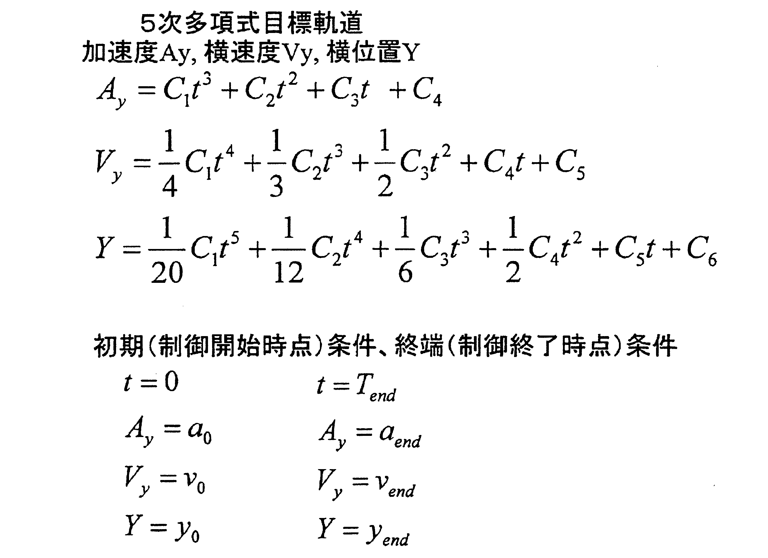
ステップS750では、演算部10は、トルクの変化率または舵角の変化率が設定閾値αを超えたか否かを判断する。トルクについては、制御対象装置30に含まれるステアリング制御装置がステアリング機構から検出する。また、設定閾値αについては、急峻なステアリング挙動を防止する観点から、予め実験等によって設定される。よって、トルクの変化率または舵角の変化率が設定閾値αを超えた場合に、目標軌道を走行する際に車両のステアリング挙動が閾値を超え、急峻なステアリング挙動があったと判断する。ステップS750において、トルクの変化率または舵角の変化率が設定閾値αを超えていないと判断された場合には、急峻なステアリング挙動がなく、目標軌道を再算出する必要がないと判断し、本処理を終了する。一方、ステップS750において、トルクまたは舵角変化率が設定閾値αを超えたと判断された場合には、演算部10は、急峻なステアリング挙動があり、目標軌道を再算出する必要があると判断し、処理の流れはステップS760に移行する。
ステップS760では、演算部10は、閾値の傾きでトルクまたは舵角を出力する。具体的には、トルクの変化率または舵角の変化率が設定閾値α未満となるようなトルクの値または舵角の値を出力する。その後、処理の流れはステップS770に移行する。
ステップS770では、演算部10は、目標軌道を再算出する。目標軌道は、次式のような時間tに対する5次の多項式を用いて得られる。Ayは加速度(横方向の加速度)、Vyは横速度(横方向の速度)、Yは横位置(横方向の位置)である。各式に次式のような初期条件および終端条件を設定することで、係数C1~C6を導出する。初期条件は、制御開始時点で設定される条件である。また、終端条件は、制御終了時点で設定される条件であり、制御終了時点に車両が位置する地点が目標地点となる。終端条件は、急峻なステアリング挙動を防止する観点から、ステップS760で出力されたトルクの値または舵角の値に基づき設定される。このように初期条件および終端条件が再設定され、目標軌道が再算出される。なお、5次の多項式の代わりに、6次以上の多項式を用いて目標軌道を算出してもよい。なお、本ステップS770にて目標軌道を再算出すると同時にまたは代わりに、車両のステアリング挙動を抑制するための挙動抑制動作を実行してもよい。挙動抑制動作としては、例えば、制御対象装置30がステアリング機構を制御することにより逸脱抑制動作の実行を中止させることや、制御対象装置30が駆動機構または制動機構を制御することにより車両を減速させること、情報出力装置40がブザーやスピーカによる音出力や表示装置やランプによる表示を用いてドライバに報知することなどが挙げられる。その後、処理の流れはステップS750に移行する。
車線逸脱抑制処理(7)において、ステップS740は演算部10内の目標軌道算出部111によって実行され、ステップS750は走行状況判断部112によって実行され、ステップS770は目標軌道再算出部113によって実行される。

(3.実施形態の効果)
本実施形態の車線逸脱抑制システム1によれば、目標地点まで車両を走行させる軌道である目標軌道を算出した後に、車両の走行状況に応じて目標軌道を再算出するので、様々な車両逸脱状況にも対応可能な目標軌道を生成することができる。
本実施形態の車線逸脱抑制システム1によれば、目標地点まで車両を走行させる軌道である目標軌道を算出した後に、車両の走行状況に応じて目標軌道を再算出するので、様々な車両逸脱状況にも対応可能な目標軌道を生成することができる。
Claims (12)
- 車両に搭載され、前記車両が走行中の車線から逸脱することを抑制する車線逸脱抑制システム(1)であって、
前記車両を走行させる目標軌道を生成する目標軌道生成部(101)と、
前記目標軌道生成部によって生成された目標軌道に沿って前記車両を走行させるための制御指令を生成して送信する制御指令送信部(102)と、
前記制御指令送信部から送信された制御指令に基づき、前記車両が走行中の車線から逸脱することを抑制する動作である逸脱抑制動作を実行する逸脱抑制動作部(30)と、
を備え、
前記目標軌道生成部は、
前記車両が走行中の車線内の前方に目標地点を設定し、設定した目標地点まで前記車両を走行させる軌道を前記目標軌道として時間に対する5次以上の多項式を用いて算出する目標軌道算出部(111)と、
前記目標軌道に沿って走行する前記車両が前記車線の延伸方向に直交する直交方向において前記目標地点から離間した後に前記目標地点へ復帰した場合に、前記目標軌道を再算出する必要があると判断する走行状況判断部(112)と、
前記目標軌道を再算出する必要があると前記走行状況判断部によって判断された場合に、前記目標軌道を時間に対する5次以上の多項式または時間に対する1次の多項式の何れか一方を用いて再算出する目標軌道再算出部(113)と、を備えること
を特徴とする車線逸脱抑制システム。 - 請求項1に記載の車線逸脱抑制システムにおいて、
前記目標軌道再算出部(113)は、前記目標軌道を再算出するために、前記車両の走行状況に応じて、時間に対する5次以上の多項式または時間に対する1次の多項式の何れか一方を選択すること
を特徴とする車線逸脱抑制システム。 - 請求項1または請求項2に記載の車線逸脱抑制システムにおいて、
前記目標軌道再算出部(113)は、時間に対する1次の多項式を用いて再算出する場合には、前記車線の延伸方向に直交する直交方向において前記車両が移動する速度である横速度を算出し、算出した横速度で前記車両を走行させる軌道を前記目標軌道として再算出すること
を特徴とする車線逸脱抑制システム。 - 請求項3に記載の車線逸脱抑制システムにおいて、
前記目標軌道再算出部(113)は、前記車両が走行する車線の曲率に応じて前記横速度を算出すること
を特徴とする車線逸脱抑制システム。 - 車両に搭載され、前記車両が走行中の車線から逸脱することを抑制する車線逸脱抑制システム(1)であって、
前記車両を走行させる目標軌道を生成する目標軌道生成部(101)と、
前記目標軌道生成部によって生成された目標軌道に沿って前記車両を走行させるための制御指令を生成して送信する制御指令送信部(102)と、
前記制御指令送信部から送信された制御指令に基づき、前記車両が走行中の車線から逸脱することを抑制するための動作である逸脱抑制動作を実行する逸脱抑制動作部(30)と、
を備え、
前記目標軌道生成部は、
前記車両が走行中の車線から最も逸脱する地点である最大逸脱地点を目標地点として設定し、設定した目標地点まで前記車両を走行させる軌道を前記目標軌道として時間に対する5次以上の多項式を用いて算出する目標軌道算出部(111)と、
前記目標軌道に沿って走行する前記車両が前記車線の延伸方向に直交する直交方向において前記車線から逸脱した後に前記車線へ向けて移動し始めた場合に、前記目標軌道を再算出する必要があると判断する走行状況判断部(112)と、
前記目標軌道を再算出する必要があると前記走行状況判断部によって判断された場合に、前記車線内の前方に目標地点を再設定し、再設定した目標地点まで前記車両を走行させる軌道を前記目標軌道として時間に対する5次以上の多項式を用いて算出する目標軌道再算出部(113)と、を備えること
を特徴とする車線逸脱抑制システム。 - 請求項5に記載の車線逸脱抑制システムにおいて、
前記走行状況判断部は、前記目標軌道に沿って走行する前記車両が前記車線から逸脱する方向に障害物が存在する場合にも、前記目標軌道を再算出する必要があると判断し、
前記目標軌道再算出部(113)は、前記障害物の存在に起因して前記目標軌道を再算出する必要があると前記走行状況判断部によって判断された場合に、前記直交方向における前記車両が走行中の車線から前記最大逸脱地点までの距離を変更することで前記目標地点を再設定し、再設定した目標地点まで前記車両を走行させる軌道を前記目標軌道として時間に対する5次以上の多項式を用いて算出すること
を特徴とする車線逸脱抑制システム。 - 車両に搭載され、前記車両が走行中の車線から逸脱することを抑制する車線逸脱抑制システム(1)であって、
前記車両を走行させる目標軌道を生成する目標軌道生成部(101)と、
前記目標軌道生成部によって生成された目標軌道に沿って前記車両を走行させるための制御指令を生成して送信する制御指令送信部(102)と、
前記制御指令送信部から送信された制御指令に基づき、前記車両が走行中の車線から逸脱することを抑制するための動作である逸脱抑制動作を実行する逸脱抑制動作部(30)と、
を備え、
前記目標軌道生成部は、
前記車両が走行中の車線内の前方に目標地点を設定し、設定した目標地点まで前記車両を走行させる軌道を前記目標軌道として時間に対する5次以上の多項式を用いて算出する目標軌道算出部(111)と、
前記車線の延伸方向に直交する直交方向における前記車両が走行する軌道と前記目標軌道との間の距離が閾値以上である場合に、前記目標軌道を再算出する必要があると判断する走行状況判断部(112)と、
前記目標軌道を再算出する必要があると前記走行状況判断部によって判断された場合に、前記車線内の前方に目標地点を再設定し、再設定した目標地点まで前記車両を走行させる軌道を前記目標軌道として時間に対する5次以上の多項式を用いて算出する目標軌道再算出部(113)と、を備えること
を特徴とする車線逸脱抑制システム。 - 車両に搭載され、前記車両が走行中の車線から逸脱することを抑制する車線逸脱抑制システム(1)であって、
前記車両を走行させる目標軌道を生成する目標軌道生成部(101)と、
前記目標軌道生成部によって生成された目標軌道に沿って前記車両を走行させるための制御指令を生成して送信する制御指令送信部(102)と、
前記制御指令送信部から送信された制御指令に基づき、前記車両が走行中の車線から逸脱することを抑制するための動作である逸脱抑制動作を実行する逸脱抑制動作部(30)と、
を備え、
前記目標軌道生成部は、
前記車両が走行中の車線内の前方に目標地点を設定し、設定した目標地点まで前記車両を走行させる軌道を前記目標軌道として時間に対する5次以上の多項式を用いて算出する目標軌道算出部(111)と、
前記目標軌道に沿って走行する前記車両が前方の障害物と接触する場合に、前記目標軌道を再算出する必要があると判断する走行状況判断部(112)と、
前記目標軌道を再算出する必要があると前記走行状況判断部によって判断された場合に、前記車両が前記障害物と接触しない地点を目標地点として再設定し、再設定した目標地点まで前記車両を走行させる軌道を前記目標軌道として時間に対する5次以上の多項式を用いて算出する目標軌道再算出部(113)と、を備えること
を特徴とする車線逸脱抑制システム。 - 車両に搭載され、前記車両が走行中の車線から逸脱することを抑制する車線逸脱抑制システム(1)であって、
前記車両を走行させる目標軌道を生成する目標軌道生成部(101)と、
前記目標軌道生成部によって生成された目標軌道に沿って前記車両を走行させるための制御指令を生成して送信する制御指令送信部(102)と、
前記制御指令送信部から送信された制御指令に基づき、前記車両が走行中の車線から逸脱することを抑制するための動作である逸脱抑制動作を実行する逸脱抑制動作部(30)と、
を備え、
前記目標軌道生成部は、
前記車両が走行中の車線内の前方に目標地点を設定し、設定した目標地点まで前記車両を走行させる軌道を前記目標軌道として時間に対する5次以上の多項式を用いて算出する目標軌道算出部(111)と、
前記目標軌道を走行する際に前記車両のステアリング挙動が閾値を超えるか否かを判断する走行状況判断部(112)と、
前記目標軌道を走行する際に前記車両のステアリング挙動が閾値を超えると前記走行状況判断部によって判断された場合に、前記車線内の前方に目標地点を再設定し、再設定した目標地点まで前記車両を走行させる軌道を前記目標軌道として前記目標軌道を走行中には前記車両のステアリング挙動が閾値未満となるように時間に対する5次以上の多項式を用いて算出する目標軌道再算出部(113)と、を備え、
さらに、前記目標軌道を走行する際に前記車両のステアリング挙動が閾値を超えると前記走行状況判断部によって判断された場合に、前記目標軌道再算出部よる前記目標軌道の再算出と同時か前記目標軌道再算出部よる前記目標軌道の再算出の代わりに、前記車両のステアリング挙動を抑制するための挙動抑制動作を実行する挙動抑制動作部(30,40)を備えること
を特徴とする車線逸脱抑制システム。 - 請求項9に記載の車線逸脱抑制システムにおいて、
前記挙動抑制動作部(30)は、前記挙動抑制動作として、前記逸脱抑制動作部による前記逸脱抑制動作の実行を中止させること
を特徴とする車線逸脱抑制システム。 - 請求項9または請求項10に記載の車線逸脱抑制システムにおいて、
前記挙動抑制動作部(30)は、前記挙動抑制動作として、前記車両を減速させること
を特徴とする車線逸脱抑制システム。 - 請求項9~請求項11の何れか1項に記載の車線逸脱抑制システムにおいて、
前記挙動抑制動作部(40)は、前記挙動抑制動作として、前記目標軌道を走行する際に前記車両のステアリング挙動が閾値を超える旨をドライバに報知すること
を特徴とする車線逸脱抑制システム。
Priority Applications (1)
| Application Number | Priority Date | Filing Date | Title |
|---|---|---|---|
| US15/739,117 US10325501B2 (en) | 2015-06-26 | 2016-06-24 | Lane deviation suppressing system |
Applications Claiming Priority (2)
| Application Number | Priority Date | Filing Date | Title |
|---|---|---|---|
| JP2015-128884 | 2015-06-26 | ||
| JP2015128884A JP6376055B2 (ja) | 2015-06-26 | 2015-06-26 | 車線逸脱抑制システム |
Publications (1)
| Publication Number | Publication Date |
|---|---|
| WO2016208710A1 true WO2016208710A1 (ja) | 2016-12-29 |
Family
ID=57585090
Family Applications (1)
| Application Number | Title | Priority Date | Filing Date |
|---|---|---|---|
| PCT/JP2016/068797 Ceased WO2016208710A1 (ja) | 2015-06-26 | 2016-06-24 | 車線逸脱抑制システム |
Country Status (3)
| Country | Link |
|---|---|
| US (1) | US10325501B2 (ja) |
| JP (1) | JP6376055B2 (ja) |
| WO (1) | WO2016208710A1 (ja) |
Cited By (1)
| Publication number | Priority date | Publication date | Assignee | Title |
|---|---|---|---|---|
| CN108725579A (zh) * | 2017-04-25 | 2018-11-02 | 纵目科技(上海)股份有限公司 | 泊车过程中的方向控制方法及系统、模型、终端及车辆 |
Families Citing this family (10)
| Publication number | Priority date | Publication date | Assignee | Title |
|---|---|---|---|---|
| JP6763343B2 (ja) * | 2017-04-12 | 2020-09-30 | トヨタ自動車株式会社 | 車線変更支援装置 |
| JP6763344B2 (ja) * | 2017-04-12 | 2020-09-30 | トヨタ自動車株式会社 | 車線変更支援装置 |
| CA3074413A1 (en) * | 2017-08-30 | 2019-03-07 | Nissan Motor Co., Ltd. | Position correction method and position error correction device for drive-assisted vehicle |
| US10988139B2 (en) * | 2017-08-30 | 2021-04-27 | Nissan Motor Co., Ltd. | Vehicle position control method and device vehicle position control device for correcting position in drive-assisted vehicle |
| CN109017984B (zh) * | 2018-07-25 | 2020-11-03 | 吉林大学 | 一种无人车的轨迹跟随控制方法、控制系统及相关装置 |
| JP7149288B2 (ja) * | 2018-12-26 | 2022-10-06 | バイドゥドットコム タイムズ テクノロジー (ベイジン) カンパニー リミテッド | 自動運転車両のための螺旋曲線に基づく垂直駐車計画システム |
| CN109765902B (zh) * | 2019-02-22 | 2022-10-11 | 阿波罗智能技术(北京)有限公司 | 无人车驾驶参考线处理方法、装置及车辆 |
| US11117577B2 (en) | 2019-02-22 | 2021-09-14 | Ford Global Technologies, Llc | Vehicle path processing |
| JP7216579B2 (ja) * | 2019-03-08 | 2023-02-01 | 日立Astemo株式会社 | 車両運動制御装置、車両運動制御方法、及び車両運動制御システム |
| US11608089B2 (en) * | 2020-11-09 | 2023-03-21 | GM Global Technology Operations LLC | Method and apparatus for automated lateral controls adaptation in response to rapid trajectory changes |
Citations (6)
| Publication number | Priority date | Publication date | Assignee | Title |
|---|---|---|---|---|
| JP2004338636A (ja) * | 2003-05-16 | 2004-12-02 | Toyota Motor Corp | 走行支援装置 |
| JP2009006881A (ja) * | 2007-06-28 | 2009-01-15 | Nissan Motor Co Ltd | 車線逸脱防止装置 |
| JP2010163164A (ja) * | 2010-02-19 | 2010-07-29 | Hitachi Automotive Systems Ltd | 走行支援装置 |
| JP2015003566A (ja) * | 2013-06-19 | 2015-01-08 | トヨタ自動車株式会社 | 逸脱防止装置 |
| JP2015230547A (ja) * | 2014-06-04 | 2015-12-21 | 株式会社デンソー | 運転操作を生成するシステムおよび方法 |
| JP2016071566A (ja) * | 2014-09-29 | 2016-05-09 | 日立建機株式会社 | 障害物回避システム |
Family Cites Families (6)
| Publication number | Priority date | Publication date | Assignee | Title |
|---|---|---|---|---|
| US9789869B2 (en) * | 2012-11-02 | 2017-10-17 | Toyota Jidosha Kabushiki Kaisha | Driving support apparatus and driving support method |
| JP6020224B2 (ja) | 2013-02-07 | 2016-11-02 | トヨタ自動車株式会社 | 目標走行軌跡生成装置 |
| JP5802241B2 (ja) | 2013-07-04 | 2015-10-28 | 富士重工業株式会社 | 車両の運転支援制御装置 |
| JP6185805B2 (ja) | 2013-09-20 | 2017-08-23 | 株式会社Subaru | 車両のレーンキープ制御装置 |
| JP6201561B2 (ja) | 2013-09-20 | 2017-09-27 | 株式会社デンソー | 走行軌道生成装置、および走行軌道生成プログラム |
| KR101502510B1 (ko) * | 2013-11-26 | 2015-03-13 | 현대모비스 주식회사 | 차량의 차선 유지 제어 장치 및 방법 |
-
2015
- 2015-06-26 JP JP2015128884A patent/JP6376055B2/ja active Active
-
2016
- 2016-06-24 US US15/739,117 patent/US10325501B2/en active Active
- 2016-06-24 WO PCT/JP2016/068797 patent/WO2016208710A1/ja not_active Ceased
Patent Citations (6)
| Publication number | Priority date | Publication date | Assignee | Title |
|---|---|---|---|---|
| JP2004338636A (ja) * | 2003-05-16 | 2004-12-02 | Toyota Motor Corp | 走行支援装置 |
| JP2009006881A (ja) * | 2007-06-28 | 2009-01-15 | Nissan Motor Co Ltd | 車線逸脱防止装置 |
| JP2010163164A (ja) * | 2010-02-19 | 2010-07-29 | Hitachi Automotive Systems Ltd | 走行支援装置 |
| JP2015003566A (ja) * | 2013-06-19 | 2015-01-08 | トヨタ自動車株式会社 | 逸脱防止装置 |
| JP2015230547A (ja) * | 2014-06-04 | 2015-12-21 | 株式会社デンソー | 運転操作を生成するシステムおよび方法 |
| JP2016071566A (ja) * | 2014-09-29 | 2016-05-09 | 日立建機株式会社 | 障害物回避システム |
Cited By (1)
| Publication number | Priority date | Publication date | Assignee | Title |
|---|---|---|---|---|
| CN108725579A (zh) * | 2017-04-25 | 2018-11-02 | 纵目科技(上海)股份有限公司 | 泊车过程中的方向控制方法及系统、模型、终端及车辆 |
Also Published As
| Publication number | Publication date |
|---|---|
| JP2017013518A (ja) | 2017-01-19 |
| US10325501B2 (en) | 2019-06-18 |
| JP6376055B2 (ja) | 2018-08-22 |
| US20180190123A1 (en) | 2018-07-05 |
Similar Documents
| Publication | Publication Date | Title |
|---|---|---|
| JP6376055B2 (ja) | 車線逸脱抑制システム | |
| JP6137194B2 (ja) | 運転支援装置及び運転支援方法 | |
| JP6849415B2 (ja) | 自動運転システム | |
| JP6305484B2 (ja) | 車両制御装置 | |
| JP7109147B2 (ja) | モータサイクルの挙動を制御する制御装置及び制御方法 | |
| WO2018211802A1 (ja) | 自動運転支援装置および自動運転支援方法 | |
| JP5974607B2 (ja) | 車両走行制御装置 | |
| JP6973978B2 (ja) | レーン・スプリッティング中のモータサイクルの挙動を制御する制御装置及び制御方法 | |
| US20090037052A1 (en) | Vehicle drive assist system | |
| CN108541325A (zh) | 驾驶辅助装置以及驾驶辅助方法 | |
| WO2018230286A1 (ja) | 車両運動制御装置、車両運動制御方法および車両運動制御システム | |
| CN103370250A (zh) | 驾驶辅助装置、驾驶辅助方法以及驾驶辅助程序 | |
| JPWO2014192368A1 (ja) | 車両の制御装置及び車両の走行制御システム | |
| JP2018065465A (ja) | 車線逸脱抑制装置 | |
| JP7008617B2 (ja) | 車両制御装置 | |
| CN107709140A (zh) | 车道脱离抑制装置 | |
| CN111661042A (zh) | 车辆控制装置 | |
| JP4277907B2 (ja) | 自動車の走行制御装置 | |
| WO2019159562A1 (ja) | 運転支援装置、運転支援方法及び運転支援システム | |
| JP2020164061A (ja) | 車両制御装置 | |
| US11130490B2 (en) | Vehicle control device | |
| JP2023047007A (ja) | 車両の走行制御装置 | |
| JP2016141387A (ja) | 車両の運転支援制御装置 | |
| JP6119526B2 (ja) | 車両用走行制御装置 | |
| JP2018127073A (ja) | 車線逸脱抑制装置 |
Legal Events
| Date | Code | Title | Description |
|---|---|---|---|
| 121 | Ep: the epo has been informed by wipo that ep was designated in this application |
Ref document number: 16814479 Country of ref document: EP Kind code of ref document: A1 |
|
| NENP | Non-entry into the national phase |
Ref country code: DE |
|
| 122 | Ep: pct application non-entry in european phase |
Ref document number: 16814479 Country of ref document: EP Kind code of ref document: A1 |