WO2016208583A1 - ターゲット保持冶具及び測定装置並びにターゲット保持方法 - Google Patents
ターゲット保持冶具及び測定装置並びにターゲット保持方法 Download PDFInfo
- Publication number
- WO2016208583A1 WO2016208583A1 PCT/JP2016/068404 JP2016068404W WO2016208583A1 WO 2016208583 A1 WO2016208583 A1 WO 2016208583A1 JP 2016068404 W JP2016068404 W JP 2016068404W WO 2016208583 A1 WO2016208583 A1 WO 2016208583A1
- Authority
- WO
- WIPO (PCT)
- Prior art keywords
- target
- measurement object
- guide
- magnet
- holding jig
- Prior art date
- Legal status (The legal status is an assumption and is not a legal conclusion. Google has not performed a legal analysis and makes no representation as to the accuracy of the status listed.)
- Ceased
Links
Images




Classifications
-
- G—PHYSICS
- G01—MEASURING; TESTING
- G01B—MEASURING LENGTH, THICKNESS OR SIMILAR LINEAR DIMENSIONS; MEASURING ANGLES; MEASURING AREAS; MEASURING IRREGULARITIES OF SURFACES OR CONTOURS
- G01B21/00—Measuring arrangements or details thereof, where the measuring technique is not covered by the other groups of this subclass, unspecified or not relevant
-
- G—PHYSICS
- G01—MEASURING; TESTING
- G01C—MEASURING DISTANCES, LEVELS OR BEARINGS; SURVEYING; NAVIGATION; GYROSCOPIC INSTRUMENTS; PHOTOGRAMMETRY OR VIDEOGRAMMETRY
- G01C15/00—Surveying instruments or accessories not provided for in groups G01C1/00 - G01C13/00
- G01C15/02—Means for marking measuring points
- G01C15/06—Surveyors' staffs; Movable markers
-
- G—PHYSICS
- G01—MEASURING; TESTING
- G01B—MEASURING LENGTH, THICKNESS OR SIMILAR LINEAR DIMENSIONS; MEASURING ANGLES; MEASURING AREAS; MEASURING IRREGULARITIES OF SURFACES OR CONTOURS
- G01B11/00—Measuring arrangements characterised by the use of optical techniques
- G01B11/08—Measuring arrangements characterised by the use of optical techniques for measuring diameters
-
- G—PHYSICS
- G01—MEASURING; TESTING
- G01B—MEASURING LENGTH, THICKNESS OR SIMILAR LINEAR DIMENSIONS; MEASURING ANGLES; MEASURING AREAS; MEASURING IRREGULARITIES OF SURFACES OR CONTOURS
- G01B11/00—Measuring arrangements characterised by the use of optical techniques
- G01B11/24—Measuring arrangements characterised by the use of optical techniques for measuring contours or curvatures
Definitions
- Measured devices that measure the distance to a measurement object include devices that use measurement light.
- Patent Literature 1 receives a light source that outputs a radiated light beam (measurement light), a target that includes an external retroreflector that reflects the measurement light, and light that is fixed integrally with the light source and reflected from the target.
- An absolute distance meter having a light receiving unit and a signal processing device that analyzes the light received by the light receiving unit and calculates the distance to the target is described.
- the absolute distance meter irradiates the target with measurement light from the light source while the target is in contact with the measurement object, receives the light reflected by the target at the light receiving unit, analyzes the received light, By calculating the distance, the distance to the measurement object in contact with the target can be measured.
- Patent Document 2 as a jig for holding a spherical reflector (target) used for measuring a bending angle of a rod-like work (pipe) such as a cylinder or a column, an outer part that holds the spherical reflector in a slidable manner is disclosed.
- a jig that includes a pair of semicircular jig structures having orientation grooves formed therein, and that the pair of semicircular jig structures are combined and fitted to the outer periphery of a pipe.
- the bending angle for each measurement part of the bar-shaped workpiece is recorded. Is going to be possible.
- a plate-like member such as a seal fin of a steam turbine may be an object to be measured.
- the object to be measured becomes thinner, unlike a rod-like workpiece such as a cylinder or a column. Since the target is spherical, when the target is brought into contact with the measurement object or moved along the measurement object, the contact position of the target is easily shifted in the thickness direction (plate thickness direction) of the measurement object. . Thus, when the contact position of the target shifts, the plate-shaped measurement object comes in contact with a direction shifted from the normal line toward the center of the spherical target, resulting in a measurement error.
- the target holding jig described in Patent Document 3 can bring the target into contact with the measurement object with high accuracy, but it is necessary to improve operability.
- the connecting portion may be a mechanism such as a magnet that is connected to an object to be measured by adsorption.
- the holding-type connecting portion is simply replaced with a magnet, it is notable. It is difficult to improve operability.
- a target holding jig is a material that holds a target including a reflection mechanism that reflects measurement light emitted from a light source, and is capable of magnetically attracting the target and a magnet.
- suction state with respect to a measuring object can be ensured, guiding the contact of the contact part of the target with respect to the end surface of a measuring object.
- the position of the guide portion can be adjusted according to the dimension of the measurement object, and the target It is possible to improve the accuracy of the guidance of the position that comes into contact with the measurement object, or improve the accuracy of the position where the connecting portion magnetically attracts the measurement object.
- magnetic adsorption to the measurement object can be easily performed and can be easily removed from the measurement object. Thereby, attachment / detachment with respect to a measuring object can be performed easily.
- the magnet has a flat surface along a side surface that is a surface extending in a direction orthogonal to the end surface and an extending direction of the end surface of the measurement object,
- the flat surface is preferably separated from the position of the contact portion of the target that contacts the measurement object by the dimension of the measurement object in the short direction of the end surface of the measurement object.
- the contact portion of the target is arranged with respect to the measurement object by magnetically attracting the flat surface of the magnet to the measurement object, the contact portion of the target is easily and high with respect to the measurement object. Can be contacted with accuracy.
- the guide portion has a side surface on which the other guide surface is a surface extending in an extending direction of the end surface of the measurement object and a direction orthogonal to the end surface. It is preferable that the magnet is fixed to the other guide surface at each position on both sides of the target in the long side direction of the end surface of the measurement object.
- each connecting portion is magnetically attracted and connected to the side surface of the measurement object on both sides of the target, so that the target can be brought into contact with the measurement object in a stable connection state.
- the magnet is preferably a neodymium-based permanent magnet.
- the target can be more reliably brought into contact with the measurement object, and the measurement accuracy can be further increased.
- this can prevent the connecting portion and the target from being electrically connected at a portion other than the circuit.
- a target holding method is a method for holding a target including a reflection mechanism that reflects measurement light emitted from a light source, and an end surface of a measurement object formed of a material capable of magnetically attracting the target and a magnet.
- a guide unit that guides a position where the target contacts the measurement object in a short side direction of the end surface of the sensor, and a coupling unit that is fixed to the guide unit and includes a magnet that can be magnetically attracted to the measurement object.
- the magnet has a flat surface along a side surface that is a surface extending in a direction orthogonal to the end surface and an extending direction of the end surface of the measurement object, and magnetic absorption is performed on the side surface of the measurement object.
- the guide portion is a space having a thickness equal to or greater than the thickness of the measurement object from the flat surface of the magnet to the side surface opposite to the side surface in a state where the magnet is magnetically attracted to the side surface of the measurement object.
- the magnet of the connecting part is connected to the measurement object by magnetic attraction, and the relative position between the target and the measurement object is regulated by the guide part, so that the target can be brought into contact with the measurement object with high accuracy.
- one target holding jig and a target can be used for the measurement of several points by connecting with a measuring object in the state in which a connection part is removable with a magnet.
- the connecting portion is configured to magnetically attract to the measurement object, the connection to the measurement object can be easily performed.
- the connection part is arrange
- the connecting portion can be easily connected to the measurement object, and a high magnetic attraction force can be ensured by magnetic attraction between the surfaces.
- the magnet of the target holding jig extends along only one side surface that is an extending direction of the end surface of the measurement object and a surface extending in a direction orthogonal to the end surface.
- the flat surface of the magnet is magnetically attracted only to one side surface of the measurement object.
- the magnetic adsorption to the measurement object can be easily performed, and the magnetic adsorption from the measurement object can be easily removed, so that the measurement object can be easily attached and detached.
- the guide portion of the target holding jig sandwiches two side surfaces which are the extending direction of the end surface of the measurement object and a surface extending in a direction perpendicular to the end surface 2
- the contact portion of the target that contacts the end surface of the measurement object is disposed between the guide surfaces, and one of them is provided so as to be movable toward or away from the other.
- the accuracy of guiding the position where the target contacts the measurement object can be improved, and the connecting portion can be magnetically attracted to the measurement object.
- the accuracy of the position to be performed can be improved.
- the target holding jig includes a detection unit that detects that the target and the measurement object are in contact, and the detection unit includes the target and the measurement object. It is preferable that a notification unit for notifying that the contact is detected is further provided, and that in the connection step, the connection is completed when the notification by the notification unit is received.
- the measurement object is preferably an annular seal fin in a steam turbine.
- the measurement object is a seal fin
- it is necessary to measure a large number of positions but by using a detachable target holding jig, the target is placed on the measurement object and moved for measurement. Measurement can be performed with a small number of targets.
- the measurement object such as a plate-like member such as a seal fin of the steam turbine and the connection part are connected by magnetic adsorption, and the target and the measurement object are relative to each other in the guide part.
- the target By regulating the position, the target can be brought into contact with a measurement object that is a plate-like member such as a seal fin of a steam turbine with high accuracy by an easy operation.
- FIG. 1 is a front view showing a schematic configuration of a target holding jig according to an embodiment of the present invention.
- FIG. 2 is a top view of the target holding jig shown in FIG.
- FIG. 3 is a bottom view of the target holding jig shown in FIG.
- FIG. 4 is a cross-sectional view showing a schematic configuration viewed from the line AA in FIG.
- FIG. 5 is a cross-sectional view showing a schematic configuration viewed from the line BB in FIG.
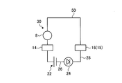
- FIG. 6 is a schematic diagram illustrating a circuit configuration of the detection unit.
- FIG. 7 is a schematic diagram illustrating a schematic configuration of a measurement apparatus including a target holding jig.
- FIG. 8 is a perspective view showing a schematic configuration of the measurement object.
- FIG. 9 is a schematic diagram showing a positional relationship between the measurement object and the target holding jig during measurement.
- the target holding jig and the measuring device of the present invention will be described by taking an example of measuring the end surface on the inner peripheral side of the ring-shaped seal fin of the steam turbine.
- the magnet is not limited to this as long as it is made of a magnetically attractable material (including a magnetic material).
- the target holding jig and the measuring device of the present invention can obtain a more remarkable effect when the seal fin is used as a measurement object.
- the position of the end face of the thin plate-like measurement object is measured. In this case, it can be suitably used.
- FIG. 1 is a front view showing a schematic configuration of a target holding jig according to an embodiment of the present invention.
- FIG. 2 is a top view of the target holding jig shown in FIG.
- FIG. 3 is a bottom view of the target holding jig shown in FIG.
- FIG. 4 is a cross-sectional view showing a schematic configuration viewed from the line AA in FIG.
- FIG. 5 is a cross-sectional view showing a schematic configuration viewed from the line BB in FIG.
- FIG. 6 is a schematic diagram illustrating a circuit configuration of the detection unit.
- the target holding jig 10 holds the target 8 and is detachably connected to the measurement object 50.
- the target 8 is a part of a measuring apparatus described later, and includes a reflection mechanism that reflects measurement light.
- the target 8 is a substantially spherical member partially formed with a notch, and a reflector that reflects measurement light is provided in the notch.
- the measurement object 50 of the present embodiment is a ring-shaped seal fin of a steam turbine (hereinafter, the measurement object 50 is also referred to as a seal fin 50).
- the target holding jig 10 includes a support part 14, a connecting part 15, a guide part 20, a battery folder 22, a light emitting part 24, a wiring 26, and a wiring 28.
- the support portion 14 is a member that becomes a base of the target holding jig 10. As shown in FIGS. 1 to 5, the support portion 14 includes a first support portion 14A and a second support portion 14B. Each of the first support portion 14A and the second support portion 14B is a plate-like member, and is connected by a screw 14D via a spacer 14C having a predetermined interval between the inner surfaces having the largest areas facing each other. ing. In the first support portion 14A, an opening portion 14Aa penetrating the inner and outer surfaces having the largest area is formed. Further, the second support portion 14B is formed with an opening 14Ba penetrating the inner and outer surfaces having the largest area.
- the openings 14Aa and 14Ba are provided so as to face each other and have an inner diameter slightly smaller than the diameter of the target 8. Then, by inserting the target 8 into each opening 14Aa, 14Ba, the target 8 places its center C between the first support part 14A and the second support part 14B, and the first support part 14A and the second support part 14B. It is held by the target holding jig 10 by being sandwiched between the support portions 14B and being held at predetermined positions in the openings 14Aa and 14Ba. 2 and 3, the openings 14 ⁇ / b> Aa and 14 ⁇ / b> Ba are shown as rectangular shapes, but may be circular, for example, and the shape is not limited as long as it has an inner diameter smaller than the diameter of the target 8.
- the notch 14Ab extended to the side surface of 14 A of 1st support parts is formed.
- the outer surface having the largest area is a surface facing the end surface 50a of the measurement object 50 when facing the measurement object (seal fin) 50 as shown in FIG. .
- the battery folder 22 and the light emitting unit 24 are arranged on the outer surface facing away from the measurement object 50.
- a wiring 26 and a wiring 28 are arranged in association with the battery folder 22 and the light emitting unit 24.
- the guide part 20 is arrange
- the guide part 20 is arrange
- the guide part 20 includes a first guide part 20A and a second guide part 20B.
- the first guide portion 20 ⁇ / b> A and the second guide portion 20 ⁇ / b> B are arranged with the top portion 8 a of the target 8 that protrudes most from the opening portion 14 ⁇ / b> Ba on the outer surface of the second support portion 14 ⁇ / b> B. It is provided facing.
- the top 8 a of the target 8 is a contact portion that contacts the end surface 50 a of the measurement object 50.
- the first guide portion 20A and the second guide portion 20B are provided with flat guide surfaces 20Aa and 20Ba facing each other with the top portion 8a of the target 8 therebetween.
- Each guide surface 20Aa, 20Ba is provided along the longitudinal direction in which the measurement object 50 extends, as shown in FIG.
- channel 21 which put the top part 8a of the target 8 is formed between each guide surface 20Aa and 20Ba. Further, as shown in FIGS.
- the first guide portion 20 ⁇ / b> A and the second guide portion 20 ⁇ / b> B have an opening hole 20 ⁇ / b> Ab for inserting a part of the target 8 protruding from the opening portion 14 ⁇ / b> Ba of the second support portion 14 ⁇ / b> B, 20Bb is formed.
- the opening holes 20Ab and 20Bb prevent the first guide part 20A and the second guide part 20B from interfering with the target 8.
- the first guide portion 20A is provided such that the guide surface 20Aa extends to both sides of the target 8 with the target 8 positioned substantially at the center.
- the first guide portion 20A has a fixed piece 20Ac that is bent perpendicular to the guide surface 20Aa, and the fixed piece 20Ac is fixed to the second support portion 14B by a screw 20Ad.
- the guide surface 20 ⁇ / b> Aa is along the one side surface 50 b of the measurement object 50. Further, as shown in FIGS.
- the first guide portion 20 ⁇ / b> A is located at a position protruding from the second support portion 14 ⁇ / b> B rather than the protruding height of the top portion 8 a of the target 8 protruding from the second support portion 14 ⁇ / b> B.
- a guide surface 20Aa is disposed.
- the side surface 50b of the measuring object 50 is a surface extending in the extending direction of the end surface 50a of the measuring object 50 and the direction orthogonal to the end surface 50a.
- the second guide portion 20B is formed such that the guide surface 20Ba is smaller than the guide surface 20Aa of the first guide portion 20A.
- the second guide portion 20B has a fixing piece 20Bc that bends perpendicularly to the guide surface 20Ba, and the fixing piece 20Bc is fixed to the second support portion 14B by screws 20Bd.
- the guide surface 20Ba is along the other side surface 50b of the measurement object 50.
- the second guide portion 20B is formed as a long hole 20Be in which a hole into which the screw 20Bd is inserted is formed in a longitudinal shape in a direction toward the first guide portion 20A.
- the second guide portion 20B is provided so that the guide surface 20Ba can move toward or away from the guide surface 20Aa of the first guide portion 20A by loosening the screw 20Bd. That is, the guide part 20 is provided so that the space
- the connecting portion 15 includes a magnet 16 and a magnet 18.
- the magnet 16 and the magnet 18 are coupled so as to be magnetically attractable to a measurement object 50 made of a material (including a magnetic body) on which the magnet can be magnetically attracted.
- the magnet 16 and the magnet 18 are arranged on the guide surface 20 ⁇ / b> Aa of the first guide portion 20 ⁇ / b> A in the guide portion 20.
- the magnet 16 and the magnet 18 are in the long side direction of the end surface 50a of the measurement object 50 in the guide surface 20Aa provided to extend to both sides of the target 8 along the side surface 50b of the measurement object 50.
- a magnet 16 is disposed on one side of the target 8 and a magnet 18 is disposed on the other side of the target 8. That is, the magnet 16 and the magnet 18 serving as the connecting portion 15 are located on both sides of the target 8 in the long side direction of the end surface 50a of the measurement object 50 with respect to the guide surface 20Aa of the first guide portion 20A in the guide portion 20. Has been placed.
- the magnet 16 and the magnet 18 provided in the first guide portion 20A of the guide portion 20 can be magnetically attracted to the measurement object 50 made of a material (including a magnetic body) that the magnet can magnetically attract.
- the magnet 16 and the magnet 18 are plate-shaped magnets, and particularly neodymium-based permanent magnets.
- the magnet 16 and the magnet 18 which are plate-shaped magnets have flat surfaces 16 a and 18 a facing the side surface 50 b of the measurement target 50.
- the magnets 16 and 18 are connected by the flat surfaces 16 a and 18 a being magnetically attracted to the side surface 50 b of the measurement object 50.
- the magnets 16 and 18 have flat surfaces 16a and 18a at positions projecting from the projecting height of the top 8a of the target 8 projecting from the second support 14B. Has been placed.
- the magnets 16 and 18 may be disposed on the guide surface 20Aa of the first guide portion 20A in the guide portion 20.
- the magnets 16 and 18 may be permanent magnets other than the neodymium system.
- the magnets 16 and 18 are not limited to permanent magnets but may be electromagnets.
- the magnets 16 and 18 may be disposed on the guide surface 20Ba of the second guide portion 20B in the guide portion 20, or may be disposed only on the guide surface 20Ba of the second guide portion 20B.
- the guide part 20 in which the magnets 16 and 18 are arranged is configured as an insulating part. That is, the magnets 16 and 18 are fixed to the support part 14 via the guide part 20 which is an insulating part. Since the insulating portion is arranged at the fixed portion between the magnets 16 and 18 and the support portion 14, no electricity flows.
- the guide portion 20 is not configured as an insulating portion, and an insulating portion is disposed between the guide portion 20 and the magnets 16 and 18, or the guide portion 20 and the support portion 14 (second support). An insulating portion may be arranged between the portion 14B).
- the target 8 is measured at or near the top (contact portion) 8 a of the target 8.
- the object 50 can be brought into contact with the end surface 50a.
- the magnets 16 and 18 bring the apex (contact portion) 8a of the target 8 or the vicinity thereof into contact with the end surface 50a of the measurement object 50, so that the dimension (thickness) of the measurement object 50 is taken into consideration.
- Flat surfaces 16a and 18a are arranged at positions away from the apex (contact portion) 8a by the size of the measurement object 50, and are provided on the first guide portion 20A. For this reason, the target 8 is held in a direction in which the measurement light can be incident and reflected in a state where the magnets 16 and 18 are magnetically attracted to the side surface 50 b of the measurement object 50 and are in contact with the measurement object 50.
- the battery folder 22 is installed on the first support part 14A of the support part 14, and a battery (not shown) is attached. In the battery folder 22, one electrode is electrically connected to the support portion 14 and the other electrode is connected to the wiring 26.
- the light emitting part 24 is installed on the first support part 14 ⁇ / b> A of the support part 14.
- the light emitting unit 24 is a light emitting diode or the like, and is an element that emits light when a current flows.
- the wiring 26 connects the other electrode of the battery folder 22 and the light emitting unit 24.
- the wiring 28 connects the light emitting unit 24 and the connecting unit 15 (which may be the magnet 16 or the magnet 18).
- the support portion 14 (first support portion 14A, second support portion 14B, spacer 14C) is made of a conductive material such as metal.
- the support portion 14 is electrically connected to one pole of the battery folder 22 and is electrically connected to the target 8.
- the light emitting unit 24 is electrically connected to the other pole of the battery folder 22 via the wiring 26 and is also electrically connected to the connecting portion 15 (magnet 16) via the wiring 28.
- the connection part 15 (magnet 16) is electrically insulated from the support part 14 and the target 8 through the guide part 20 which is an insulation part.
- the target holding jig 10 becomes the detection unit 30 with the target 8, the support unit 14, the connection unit 15 (magnet 16), the battery folder 22, the wiring 26, and the wiring 28.
- the detection unit 30 forms a single series circuit including the light emitting unit 24 and the measurement object 50.
- the detection unit 30 includes a target 8, a support unit 14, a connection unit 15 (magnet 16), a battery folder 22, a wiring 26, and a wiring 28. 8 the support part 14, the battery folder 22, the wiring 26, the light emitting part 24, the wiring 28, and the connection part 15 (magnet 16) are connected in series in this order.
- the detection part 30 will contact the connection part 15 (magnet 16) and the measuring object 50, and if the target 8 and the measurement object 50 are contacted, it will measure with the connection part 15 (magnet 16).
- the object 50 and the target 8 are connected in series to form one closed circuit.
- a current flows from the battery folder 22 to which the battery is attached, and light is output from the light emitting unit 24 when the current flows through the light emitting unit 24.
- electricity does not flow, and thus the light emitting unit 24 does not emit light.
- the target holding jig 10 is configured as described above.
- the target 8 is supported by the support 14 and the magnets 16 and 18 disposed in the guide 20 (first guide 20A) are magnetically attracted to the measurement target 50.
- the measurement object 50 can be connected.
- the target holding jig 10 can regulate the position of the measuring object 50 with the guide part 20 (first guide part 20A).
- the magnets 16 and 18 are magnetically attracted to the measurement object 50, whereby the position where the target 8 contacts the measurement object 50 is regulated by the guide unit 20 (first guide unit 20A), and the target The movement of the end surface 50a of the measuring object 50 in the eighth direction in the short side direction is restricted.
- the contact position between the measurement object 50 and the target 8 can be set within a predetermined range, and the displacement of the contact position between the measurement object 50 and the target 8 can be reduced. Therefore, the user can perform the measurement using the target 8 with high accuracy by using the target holding jig 10 of the present embodiment.
- the target holding jig 10 since the target holding jig 10 has a configuration in which the magnets 16 and 18 are magnetically attracted to the measurement object 50, the target holding jig 10 is connected to the measurement object 50 as compared with the sandwiching type magnet described in the invention of Patent Document 3. Can be easily performed.
- the magnets 16 and 18 are disposed in the guide unit 20 (first guide unit 20A) that guides the position where the target 8 contacts the measurement object 50, the target 8 is moved to the measurement object 50 by magnetic attraction. The contact position can be guided.
- the target holding jig 10 has flat surfaces 16a and 18a in which the magnets 16 and 18 are along the side surface 50b of the measurement object 50. For this reason, by magnetically attracting the flat surfaces 16a and 18a to the side surface 50b of the measurement object 50, the magnets 16 and 18 can be easily connected to the measurement object 50, and magnetic adsorption between the surfaces is possible. Therefore, a high magnetic attractive force can be secured.
- the measurement object 50 is sandwiched between the guide surface 20Aa and the guide surface 20Ba. In this case, as shown in FIGS. A space larger than the thickness of the measurement object 50 is required on the side surface 50b side opposite to the side surface 50b of the measurement object 50 from the flat surfaces 16a and 18a of the magnets 16 and 18.
- the magnets 16 and 18 have flat surfaces 16a and 18a along only one side surface 50b of the measurement object 50, as shown in FIGS. For this reason, the magnetic attraction to the measuring object 50 can be facilitated, and the magnetic attraction from the measuring object 50 can be easily removed. Thereby, attachment / detachment with respect to the measuring object 50 can be performed easily.
- the target holding jig 10 has flat surfaces 16 a and 18 a in which the magnets 16 and 18 extend along the side surface 50 b of the measurement object 50, and contacts the measurement object 50.
- Flat surfaces 16a and 18a are arranged away from the position of the top (contact part) 8a of the target 8 by the size of the measurement object 50. For this reason, since the flat surfaces 16a and 18a of the magnets 16 and 18 are magnetically attracted to the measurement object 50, the top part (contact part) 8a of the target 8 is arranged with respect to the measurement object 50.
- the top portion (contact portion) 8a can be easily brought into contact with the measurement object 50 with high accuracy.
- the target holding jig 10 has a first guide portion 20A and a second guide portion 20B in which the guide portion 20 sandwiches the two side surfaces 50b of the measurement object 50, and an end surface of the measurement object 50 between them.
- the top part (contact part) 8a of the target 8 which contacts 50a is arrange
- the target holding jig 10 is provided only in the first guide portion 20A between the first guide portion 20A and the second guide portion 20B where the magnets 16 and 18 sandwich the two side surfaces 50b of the measurement object 50. ing.
- the second guide portion 20B restricts the magnetic object from being shaken due to insufficient magnetic adsorption when the magnets 16 and 18 of the first guide portion 20A are magnetically attracted to the measurement object 50. To do. Thereby, the magnetic adsorption state with respect to the measuring object 50 can be ensured while guiding the contact of the top 8a of the target 8 with the end surface 50a of the measuring object 50.
- one of the first guide part 20A and the second guide part 20B (second guide part 20B in the present embodiment) sandwiching the two side surfaces 50b of the measurement object 50 is the other (in this embodiment, the second guide part 20B).
- the first guide portion 20A) is provided so as to be able to move toward or away from the first guide portion 20A). For this reason, the space
- the accuracy of guiding the position where the target 8 contacts the measurement object 50 can be improved,
- the accuracy of the position where the magnets 16 and 18 are magnetically attracted to the measurement object 50 can be improved.
- the guide portion 20 (first guide portion 20 ⁇ / b> A) has a guide surface 20 ⁇ / b> Aa along the side surface 50 b of the measurement object 50, and the magnets 16 and 18 are the length of the end surface 50 a of the measurement object 50. In the side direction, it is fixed to the guide surface 20Aa at each position on both sides with the target 8 interposed therebetween. For this reason, the magnets 16 and 18 are magnetically attracted and connected to the side surface 50b of the measurement object 50 on both sides of the target 8 so that the target 8 can be brought into contact with the measurement object 50 in a stable connection state. it can.
- the magnets 16 and 18 are neodymium permanent magnets. For this reason, a strong magnetic adsorption state can be secured stably.
- the target holding jig 10 can determine whether the target 8 has surely contacted the measurement object 50 by the detection unit 30. Thereby, it can suppress measuring in the state where the measuring object 50 and the target 8 are not contacting, and it becomes possible to perform the measurement using the target 8 with high precision.
- the target holding jig 10 is configured such that the detection unit 30 is a circuit through which a current flows when the target 8 and the coupling unit 15 (magnet 16) are in contact with the measurement object 50, so that the user can attach the target holding jig to the measurement object 50. It is possible to detect whether the target 8 and the measurement object 50 are in contact with each other only when the operation of mounting 10 is performed.
- reporting part is provided, and when the detection part 30 detects the contact with the target 8 and the measurement object 50, since an electric current will flow and the light emission part 24 will light-emit, a target 8 and measurement will be carried out visually. It can be recognized that the object 50 has come into contact.
- the method of notifying the user that the target 8 and the measurement object 50 are in contact with each other by causing the light emitting unit 24 to emit light is not limited to light emission.
- the target holding jig 10 can use various mechanisms for transmitting to the user's five senses as a notification method.
- the target holding jig 10 may be provided with an audio output unit that emits sound instead of the light emitting unit 24.
- the target holding method is arranged on the side of the support unit 14 that faces the measurement object 50 in the state where it is in contact with the measurement object 50, and the end face 50 a of the measurement object 50.
- the guide unit 20 guides the position where the target 8 contacts the measurement object 50 in the short side direction, and magnets 16 and 18 fixed to the guide unit 20 and coupled to the measurement object 50 so as to be magnetically attractable.
- the guide unit 20 guides the position where the target 8 contacts the measurement object 50, and the magnets 16, 18 are moved to the measurement object 50 at the position where the target 8 contacts the measurement object 50. And a connecting step of connecting them by magnetic adsorption.
- the position of the measuring object 50 can be regulated by the guide part 20 (first guide part 20A).
- the magnets 16 and 18 are magnetically attracted to the measurement object 50, whereby the position where the target 8 contacts the measurement object 50 is regulated by the guide unit 20 (first guide unit 20A), and the target The movement of the end surface 50a of the measuring object 50 in the eighth direction in the short side direction is restricted.
- the contact position between the measurement object 50 and the target 8 can be set within a predetermined range, and the displacement of the contact position between the measurement object 50 and the target 8 can be reduced. Therefore, the user can perform the measurement using the target 8 with high accuracy by using the target holding jig 10 of the present embodiment.
- the target holding jig 10 since the target holding jig 10 has a configuration in which the magnets 16 and 18 are magnetically attracted to the measurement object 50, the target holding jig 10 can be attached to the measurement object 50 in comparison with the sandwiching type connecting portion described in the invention of Patent Document 3. Connection can be easily performed. Moreover, since the magnets 16 and 18 are disposed in the guide unit 20 (first guide unit 20A) that guides the position where the target 8 contacts the measurement object 50, the target 8 is moved to the measurement object 50 by magnetic attraction. The contact position can be guided.
- the magnets 16 and 18 of the target holding jig 10 have flat surfaces 16a and 18a along the side surface 50b of the measurement object 50.
- the flat surfaces of the magnets 16 and 18 are used. 16a and 18a are magnetically attracted to the side surface 50b of the measuring object 50. Thereby, it is possible to easily connect the magnets 16 and 18 to the measurement object 50, and it is possible to secure a high magnetic attraction force by magnetic attraction between the surfaces.
- the magnets 16 and 18 of the target holding jig 10 have flat surfaces 16a and 18a along only one side surface 50b of the measurement object 50.
- the magnets 16 and 18 are used.
- the flat surfaces 16 a and 18 a are magnetically attracted to one side surface 50 b of the measurement object 50.
- the target holding method includes a first guide part 20A and a second guide part 20B in which the guide part 20 of the target holding jig 10 sandwiches the two side surfaces 50b of the measurement object 50, and the measurement object is between them.
- the top part (contact part) 8a of the target 8 that contacts the end face 50a of the 50 is disposed, and one of the targets 8 is provided so as to be able to move toward or away from the other. Accordingly, the guide unit 20 is moved and then guided.
- interval of 20 A of 1st guide parts and the 2nd guide part 20B is adjusted according to the dimension of the measuring object 50, the precision of the guidance of the position where the target 8 contacts the measuring object 50 is improved. Or the accuracy of the position where the magnets 16 and 18 are magnetically attracted to the measurement object 50 can be improved.
- the target holding jig 10 further includes a detection unit 30 and a light emitting unit (notification unit) 24, and in the connection step, the connection is completed when the light emitting unit 24 reports.
- a user can be made to recognize that the target 8 and the measuring object 50 contacted, and workability
- FIG. 7 is a schematic diagram illustrating a schematic configuration of a measurement apparatus including a target holding jig.
- FIG. 8 is a perspective view showing a schematic configuration of the measurement object.
- FIG. 9 is a schematic diagram showing a positional relationship between the measurement object and the target holding jig during measurement.
- the measuring apparatus 80 including the target holding jig 10 includes a target 8, a target holding jig 10, and a measuring apparatus main body 82.
- the target 8 is held by the target holding jig 10 and is in contact with the measurement object (seal fin) 50 by the target holding jig 10 at the time of measurement.
- the measuring device main body 82 includes a light source 82a, a light receiving unit 82b, and a processing unit 82c.
- the measuring apparatus main body 82 is provided with a head 84 and an optical system 86 that irradiate the measuring light toward the target 8 and guide the light reflected by the target 8 to the measuring apparatus main body 82.
- the measurement light and the reflected light are indicated by a symbol L.
- the light source 82a outputs measurement light.
- the light source 82a outputs, for example, laser light having a predetermined wavelength as measurement light.
- the light receiving unit 82b is a light receiving element that detects the reached light.
- the light receiving unit 82 b detects light having the wavelength of the measurement light reflected by the target 8.
- the processing unit 82c controls the operation of each unit of the measuring device 80. Further, the processing unit 82c measures the distance to the target 8 by analyzing the detection result of the light receiving unit 82b and the information of the measurement light output from the light source 82a, and calculates the difference caused by the shape of the target 8 The distance to the measurement target object 50 is measured by removing with.
- the head 84 is disposed in a path through which the measurement light output from the light source 82a passes, and adjusts the direction in which the measurement light is irradiated.
- the optical system 86 is disposed between the light source 82 a and the head 84 and between the light receiving unit 82 b and the head 84, outputs the light output from the light source 82 a toward the head 84, and enters the head 84. The light is guided to the light receiving part 82b.
- the target holding jig 10 is installed at the measurement position of the measurement object 50 in a state where the measurement light irradiated to the target 8 and received by the target 8 can be received.
- the measurement object (seal fin) 50 of the present embodiment is installed on a seal ring 102 disposed inside the seal attachment ring 100 as shown in FIG.
- the seal fin 50 protrudes radially inward of the seal ring 102.
- a plurality of seal fins 50 are provided on the seal ring 102.
- the steam turbine includes a plurality of seal rings 102, the number of seal fins 50 corresponding to the number of seal rings 102 is arranged. As shown in FIG.
- the measuring device 80 is provided with a target holding jig 10 that holds the target 8 in the circumferential direction of the seal fin 50 arranged in a ring shape, and at the center of the ring shape of the seal fin 50.
- a head 84 is installed, and the measuring apparatus main body 82 is connected to the head 84.
- the measurement device 80 outputs measurement light from the measurement device main body 82 to the target 8 via the head 84, and the light reflected by the target 8 via the head 84 is received by the measurement device main body 82 and received. Can be measured to measure the distance to the measurement object 50. Further, the diameter and roundness of the seal fin 50 can be measured by moving the target holding jig 10 on the seal fin 50 and measuring a plurality of positions on the seal fin 50. That is, the target holding jig 10 of the present embodiment is movable along the side surface 50b of the measurement object 50 in a state where the magnets 16 and 18 are magnetically attracted to the side surface 50b of the measurement object 50.
- the measurement object 50 is a seal fin as in the present embodiment, it is necessary to measure a large number of positions, but the target 8 is used as the measurement object 50 by using the detachable target holding jig 10.
- the target holding jig 10 is provided with the guide portion 20, so that the target 8 can be brought into contact with the measurement object 50 with high accuracy at the time of mounting.
- the target holding jig 10 can notify the detection unit 30 and the light emitting unit 24 that the target 8 has come into contact with the measurement object 50, the installation work of the target 8 by the user can be simplified.
Landscapes
- Physics & Mathematics (AREA)
- General Physics & Mathematics (AREA)
- Engineering & Computer Science (AREA)
- Radar, Positioning & Navigation (AREA)
- Remote Sensing (AREA)
- Length Measuring Devices By Optical Means (AREA)
- Length Measuring Devices With Unspecified Measuring Means (AREA)
- A Measuring Device Byusing Mechanical Method (AREA)
Abstract
ガイド部は、測定対象物の端面の延在方向及び端面に直交する方向に延在する面である2つの側面を挟み込む2つのガイド面を有し、各ガイド面の間に測定対象物の端面に接触するターゲットの接触部が配置され、一方のガイド面が支持部に固定された他方のガイド面に対して接近または離隔する移動を可能に設けられ、連結部は、ガイド部の各ガイド面の間であって支持部に固定された他方のガイド面にのみに配置され、磁石は、測定対象物の端面の延在方向及び端面に直交する方向に延在する面である側面に沿っている平坦面を有し、測定対象物の側面に磁気吸着可能であり、ガイド部は、磁石が測定対象物の側面に磁気吸着した状態で磁石の平坦面から側面の反対側の側面側に前記測定対象物の厚さ以上の空間を有する、ターゲット保持冶具をなし、磁石が測定対象物の側面に磁気吸着した状態で測定対象物の側面に沿って移動可能である。
Description
本発明は、測定対象物と接触するターゲットを保持するターゲット保持冶具及び測定装置並びにターゲット保持方法に関する。
測定対象物までの距離を測定する測定装置には、測定光を用いて測定を行う装置がある。例えば、特許文献1には、放射光ビーム(測定光)を出力する光源と、測定光を反射する外部再帰反射器を備えるターゲットと、光源と一体で固定されターゲットから反射された光を受光する受光部と、受光部で受光した光を解析してターゲットまでの距離を算出する信号処理装置と、を有する絶対距離計が記載されている。絶対距離計は、ターゲットを測定対象物に接触させた状態で、光源からターゲットに測定光を照射し、ターゲットで反射された光を受光部で受光し、受光した光を解析し、ターゲットまでの距離を算出することで、ターゲットが接触している測定対象物までの距離を測定することができる。
特許文献2には、筒体や柱体等の棒状ワーク(パイプ)の曲がり角度を測定するのに用いられる球状のリフレクタ(ターゲット)を保持する冶具として、球状のリフレクタをスライド可能に保持する外向き溝が形成された一対の半円形冶具構成体を備え、当該一対の半円形冶具構成体を互いに合体してパイプの外周に嵌合装着される冶具が記載されている。特許文献2には、この冶具に沿ってターゲットを移動させることで、棒状ワークの曲がり角度を簡単に測定することができるのに加えて、棒状ワークの測定部位毎の曲がり角度を記録に残すことが可能になるとしている。
特許文献1に記載されているような装置を用いて、測定対象物までの距離を測定する場合、ターゲットが測定対象物に接触していないと、測定対象物との距離や測定部位の曲がり角度を正確に測定することができない。
ここで、蒸気タービンのシールフィン等の板状部材が測定対象物となる場合がある。シールフィン等の板状部材の端面を測定する場合では、筒体や柱体等の棒状ワークとは異なり、測定対象物が細くなる。ターゲットが球形であるため、ターゲットを測定対象物に接触させた時や、測定対象物に沿って移動させた時、ターゲットの接触位置が測定対象物の厚み方向(板厚方向)にずれ易くなる。このように、ターゲットの接触位置がずれてしまうと、板状の測定対象物が球状のターゲットの中心に向かう法線からずれた向きで接触することになり、測定誤差が生じる。
そこで、特許文献3に記載のターゲット保持冶具は、高い精度でターゲットを測定対象物に接触させるようにしている。このターゲット保持冶具は、光源から射出された測定光を反射する反射機構を備えるターゲットを保持し、ターゲットと測定対象物の端面とを接触させるターゲット保持冶具であって、測定対象物と接触させた状態でターゲットを支持する支持部と、支持部の測定対象物と対向する側に配置され、測定対象物の端面の短辺方向においてターゲットが測定対象物に接触する位置を規制し、かつ、ターゲットの測定対象物の端面の短辺方向への移動を規制するガイド部と、支持部に固定され、測定対象物に着脱可能に連結する連結部と、を備える。
特許文献3に記載されているターゲット保持冶具では、連結部は、測定対象物を挟持することで測定対象物に連結する、いわゆる洗濯ばさみと同様の機構である。この挟持タイプの連結部は、ターゲットを支持する支持部に対してターゲットおよびガイド部を間においた両側に設けられている。このような挟持タイプの連結部は、挟持する測定対象物の先端の片側がテーパ状に形成されている場合に挟持した状態が滑りやすくなるおそれがある。また、挟持タイプの連結部は、その挟持動作に遊びがあるため、測定対象物をガイド部で案内しながら挟み込んで手を離せるまでに時間を要する。また、挟持タイプの連結部は、両側に設けられているため、両手で操作が必要となる。このように、特許文献3に記載のターゲット保持冶具は、高い精度でターゲットを測定対象物に接触させることができるが、操作性を向上させる必要がある。なお、特許文献3には、連結部を磁石等、吸着により測定対象物に連結される機構としてもよいことが示されているが、単に挟持タイプの連結部を磁石に換えるだけでは、顕著に操作性を向上させることは難しい。
本発明は、上述した課題を解決するものであり、容易な操作により高い精度でターゲットを測定対象物に接触させることができるターゲット保持冶具及び測定装置並びにターゲット保持方法を提供することを目的とする。
上記の目的を達成するための本発明の一態様に係るターゲット保持冶具は、光源から射出された測定光を反射する反射機構を備えるターゲットを保持し、前記ターゲットと磁石が磁気吸着可能な材料で形成された測定対象物の端面とを接触させるターゲット保持冶具であって、前記測定対象物と接触させた状態で前記ターゲットを支持する支持部と、前記支持部の前記測定対象物と対向する側に配置され、前記測定対象物の端面の短辺方向において前記ターゲットが前記測定対象物に接触する位置を案内するガイド部と、前記ガイド部に固定され、前記測定対象物に磁気吸着可能な磁石を有する連結部と、を備え、前記ガイド部は、前記測定対象物の端面の延在方向及び端面に直交する方向に延在する面である2つの側面を挟み込む2つのガイド面を有し、各前記ガイド面の間に前記測定対象物の端面に接触する前記ターゲットの接触部が配置され、一方の前記ガイド面が前記支持部に固定された他方の前記ガイド面に対して接近または離隔する移動を可能に設けられ、前記連結部は、前記ガイド部の各前記ガイド面の間であって前記支持部に固定された他方の前記ガイド面にのみに配置され、前記磁石は、前記測定対象物の端面の延在方向及び端面に直交する方向に延在する面である側面に沿っている平坦面を有し、前記測定対象物の側面に磁気吸着可能であり、前記ガイド部は、前記磁石が前記測定対象物の側面に磁気吸着した状態で前記磁石の前記平坦面から前記側面の反対側の側面側に前記測定対象物の厚さ以上の空間を有する、ターゲット保持冶具をなしており、前記磁石が前記測定対象物の側面に磁気吸着した状態で前記測定対象物の側面に沿って移動可能である。
従って、連結部の磁石が測定対象物と磁気吸着により連結し、かつガイド部でターゲットと測定対象物との相対位置を規制することで、高い精度でターゲットを測定対象物に接触させることができる。また、連結部が磁石により着脱可能な状態で、測定対象物に連結することで、1つのターゲット保持冶具及びターゲットを複数点の測定に用いることができる。特に、連結部が測定対象物に磁気吸着する構成であるため、測定対象物への連結を容易に行うことができる。しかも、連結部は、ターゲットが測定対象物に接触する位置を案内するガイド部に配置されているため、磁気吸着によってターゲットが測定対象物に接触する位置を案内することができる。しかも、測定対象物の側面に対して磁石の平坦面を磁気吸着することで、測定対象物に連結部を連結し易くすることができると共に、面間での磁気吸着により高い磁気吸着力を確保することができる。しかも、対向するガイド部の間に測定対象物の端面を挿入することで、測定対象物の端面に対するターゲットの接触部の接触を案内することができる。しかも、連結部が、ガイド部の各ガイド面の間であって一方のガイド部のみに配置されていることで、連結部のない他方のガイド部は、一方のガイド部の連結部を測定対象物に磁気吸着させる際に、磁気吸着が不十分で測定対象物に対して動揺することを規制する。これにより、測定対象物の端面に対するターゲットの接触部の接触を案内しつつ、測定対象物に対する磁気吸着状態を確保することができる。しかも、ガイド部が、ガイド面の一方が他方に対して接近または離隔する移動を可能に設けられていることで、測定対象物の寸法に合わせてガイド部の位置を調整することができ、ターゲットが測定対象物に接触する位置の案内の精度を向上したり、連結部が測定対象物に磁気吸着する位置の精度を向上したりすることができる。
本発明の一態様に係るターゲット保持冶具では、前記磁石は、前記測定対象物の端面の延在方向及び端面に直交する方向に延在する面である1つの側面にのみ沿っている平坦面を有し、前記測定対象物の前記1つの側面にのみ磁気吸着可能であることが好ましい。
従って、測定対象物への磁気吸着を容易にでき、また測定対象物から外し易くなる。これにより、測定対象物に対する着脱を容易に行うことができる。
本発明の一態様に係るターゲット保持冶具では、前記磁石は、前記測定対象物の端面の延在方向及び端面に直交する方向に延在する面である側面に沿っている平坦面を有し、前記平坦面は、前記測定対象物の端面の短手方向において、前記測定対象物に接触する前記ターゲットの接触部の位置から前記測定対象物の寸法の分、離れていることが好ましい。
従って、磁石の平坦面を測定対象物に磁気吸着させることで、ターゲットの接触部が測定対象物に対して配置されるため、ターゲットの接触部を測定対象物に対して容易に、かつ、高い精度で接触させることができる。
本発明の一態様に係るターゲット保持冶具では、前記ガイド部は、他方の前記ガイド面が、前記測定対象物の端面の延在方向及び端面に直交する方向に延在する面である側面に沿って設けられ、前記連結部は、前記測定対象物の端面の長辺方向において、前記ターゲットの両側のそれぞれの位置の他方の前記ガイド面に前記磁石が固定されていることが好ましい。
従って、各連結部がターゲットの両側で測定対象物の側面に磁気吸着して連結することで、ターゲットを測定対象物に対して安定した連結状態で接触させることができる。
本発明の一態様に係るターゲット保持冶具では、前記磁石は、ネオジム系の永久磁石であることが好ましい。
従って、強固な磁気吸着状態を安定して確保することができる。
本発明の一態様に係るターゲット保持冶具では、前記ターゲットと前記測定対象物とが接触していることを検出する検出部と、前記検出部が前記ターゲットと前記測定対象物との接触を検出したことを報知する報知部と、をさらに備えることが好ましい。
従って、測定対象物にターゲットをより確実に接触させることができ、測定精度をより高くすることができる。
本発明の一態様に係るターゲット保持冶具では、前記検出部は、前記ターゲット及び前記連結部と接続された電源を有し、前記ターゲットと前記連結部と前記電源と前記報知部とが直列で接続され、前記ターゲット及び前記連結部が前記測定対象物と接触すると、前記ターゲットと前記連結部と前記電源と前記報知部と前記測定対象物とが閉じられた回路となることが好ましい。
従って、測定対象物にターゲット保持冶具を連結させるために連結部を接触させつつ位置調整するのみで、ターゲットが測定対象物に接触した状態になったか否かを知ることができる。
本発明の一態様に係るターゲット保持冶具では、前記ガイド部は、前記支持部と前記連結部との間に配置され、前記支持部と前記連結部とを絶縁する絶縁部からなることが好ましい。
従って、これにより、連結部とターゲットとが、回路以外の部分で電気的に繋がることを防止できる。
本発明の一態様に係るターゲット保持冶具では、前記報知部は、発光する発光部であることが好ましい。
従って、ターゲットと測定対象物とが接触したかを視覚でわかりやすく知ることができる。
本発明の一態様に係るターゲット保持冶具では、前記測定対象物は、蒸気タービンにおける円環状のシールフィンであることが好ましい。
従って、測定対象物をシールフィンとした場合、多数の位置についての測定が必要となるが、着脱可能なターゲット保持冶具を用いて、ターゲットを測定対象物に設置し移動させながら計測を行うことで、少ないターゲットで計測を行うことができる。
本発明の一態様に係る測定装置は、上記のいずれかに記載のターゲット保持冶具と、前記ターゲット保持冶具に保持されたターゲットと、前記ターゲットに測定光を照射する光源と前記ターゲットで反射された測定光を受光する受光部と前記受光部で受光した結果を解析する処理部とを備える測定装置本体と、を有する。
従って、ターゲットと測定対象物とを高い精度で接触できるため、つまり位置ずれを抑制できるため、高い精度で測定対象物までの距離を測定することができる。
本発明の一態様に係るターゲット保持方法は、光源から射出された測定光を反射する反射機構を備えるターゲットを保持し、前記ターゲットと磁石が磁気吸着可能な材料で形成された測定対象物の端面とを接触させるターゲット保持方法であって、前記測定対象物と接触させた状態で前記ターゲットを支持する支持部と、前記支持部の前記測定対象物と対向する側に配置され、前記測定対象物の端面の短辺方向において前記ターゲットが前記測定対象物に接触する位置を案内するガイド部と、前記ガイド部に固定され、前記測定対象物に磁気吸着可能な磁石を有する連結部と、を備え、前記磁石が前記測定対象物の端面の延在方向及び端面に直交する方向に延在する面である側面に沿っている平坦面を有し、前記測定対象物の側面に磁気吸着可能であり、前記ガイド部は、前記磁石が前記測定対象物の側面に磁気吸着した状態で前記磁石の前記平坦面から前記側面の反対側の側面側に前記測定対象物の厚さ以上の空間を有する、ターゲット保持冶具を用い、前記ガイド部により前記ターゲットが前記測定対象物に接触する位置を案内する案内工程と、前記ターゲットが前記測定対象物に接触した位置で前記磁石の前記平坦面を前記測定対象物の側面に磁気吸着させて連結させる連結工程と、前記ターゲット保持冶具を前記測定対象物上において移動させ前記測定対象物上の複数の位置の測定を行う工程と、を含む。
従って、連結部の磁石が測定対象物と磁気吸着により連結し、かつガイド部でターゲットと測定対象物との相対位置を規制することで、高い精度でターゲットを測定対象物に接触させることができる。また、連結部が磁石により着脱可能な状態で、測定対象物に連結することで、1つのターゲット保持冶具及びターゲットを複数点の測定に用いることができる。特に、連結部が測定対象物に磁気吸着する構成であるため、測定対象物への連結を容易に行うことができる。しかも、連結部は、ターゲットが測定対象物に接触する位置を案内するガイド部に配置されているため、磁気吸着によってターゲットが測定対象物に接触する位置を案内することができる。しかも、測定対象物に連結部を連結し易くすることができると共に、面間での磁気吸着により高い磁気吸着力を確保することができる。
本発明の一態様に係るターゲット保持方法では、前記ターゲット保持冶具の前記磁石が前記測定対象物の端面の延在方向及び端面に直交する方向に延在する面である1つの側面にのみ沿っている平坦面を有しており、前記連結工程では、前記磁石の前記平坦面を前記測定対象物の1つの側面にのみ磁気吸着させることが好ましい。
従って、測定対象物への磁気吸着を容易にでき、また測定対象物からの磁気吸着を外し易くなることから、測定対象物に対する着脱を容易に行うことができる。
本発明の一態様に係るターゲット保持方法では、前記ターゲット保持冶具の前記ガイド部が前記測定対象物の端面の延在方向及び端面に直交する方向に延在する面である2つの側面を挟み込む2つのガイド面を有し、各前記ガイド面の間に前記測定対象物の端面に接触する前記ターゲットの接触部が配置され、一方が他方に対して接近または離隔する移動を可能に設けられており、前記案内工程では、前記測定対象物の寸法に応じて前記ガイド部を移動させてから案内することが好ましい。
従って、対向する各ガイド部の間隔が測定対象物の寸法に応じて調整されるため、ターゲットが測定対象物に接触する位置の案内の精度を向上したり、連結部が測定対象物に磁気吸着する位置の精度を向上したりすることができる。
本発明の一態様に係るターゲット保持方法では、前記ターゲット保持冶具は、前記ターゲットと前記測定対象物とが接触していることを検出する検出部と、前記検出部が前記ターゲットと前記測定対象物との接触を検出したことを報知する報知部と、をさらに備えており、前記連結工程では、前記報知部による報知があった場合に連結完了とすることが好ましい。
従って、ユーザにターゲットと測定対象物とが接触したことを認識させ、作業性を向上することができる。
本発明の一態様に係るターゲット保持方法では、前記測定対象物は、蒸気タービンにおける円環状のシールフィンであることが好ましい。
従って、測定対象物をシールフィンとした場合、多数の位置についての測定が必要となるが、着脱可能なターゲット保持冶具を用いて、ターゲットを測定対象物に設置し移動させながら計測を行うことで、少ないターゲットで計測を行うことができる。
本発明のターゲット保持冶具及び測定装置によれば、蒸気タービンのシールフィン等の板状部材等の測定対象物と連結部が磁気吸着により連結し、かつガイド部でターゲットと測定対象物との相対位置を規制することで、容易な操作により高い精度でターゲットを蒸気タービンのシールフィン等の板状部材である測定対象物に接触させることができる。
以下、この発明につき図面を参照しつつ詳細に説明する。なお、この実施例によりこの発明が限定されるものではない。また、下記実施例における構成要素には、当業者が容易に想定できるもの、あるいは実質的に同一のものが含まれる。例えば、以下に説明する実施例では、本発明のターゲット保持冶具及び測定装置を蒸気タービンのリング形状のシールフィンの内周側の端面を測定する場合を例に挙げて説明するが、測定対象物は、磁石が磁気吸着可能な材料(磁性体を含む)からなる物であれば、これに限定されない。本発明のターゲット保持冶具及び測定装置は、シールフィンを測定対象物とした場合に、より顕著な効果を得ることができるが、シールフィンと同様に薄板状の測定対象物の端面の位置を測定する場合も好適に用いることができる。
図1は、本発明の一実施例に係るターゲット保持冶具の概略構成を示す正面図である。図2は、図1に示すターゲット保持冶具の上面図である。図3は、図1に示すターゲット保持冶具の底面図である。図4は、図1のA-A線から見た概略構成を示す断面図である。図5は、図1のB-B線から見た概略構成を示す断面図である。図6は、検出部の回路構成を示す模式図である。
ターゲット保持冶具10は、ターゲット8を保持し、測定対象物50に着脱可能に連結される。ここで、ターゲット8は、後述する測定装置の一部であり、測定光を反射する反射機構を備えている。具体的には、ターゲット8は、一部に切欠きが形成された略球状の部材であり、切欠きに測定光を反射するリフレクタが設置されている。本実施形態の測定対象物50は、蒸気タービンのリング形状のシールフィンである(以下、測定対象物50をシールフィン50ともいう。)。
ターゲット保持冶具10は、支持部14と、連結部15と、ガイド部20と、電池フォルダ22と、発光部24と、配線26と、配線28と、を有する。
支持部14は、ターゲット保持冶具10の土台となる部材である。支持部14は、図1から図5に示すように、第一支持部14A及び第二支持部14Bを備えている。第一支持部14A及び第二支持部14Bは、それぞれ板状の部材であり、面積が最も大きい内面が互いに向き合わされた相互間に所定の間隔を空けるスペーサ14Cを介在してネジ14Dにより連結されている。第一支持部14Aは、面積が最も大きい内外面に貫通する開口部14Aaが形成されている。また、第二支持部14Bは、面積が最も大きい内外面に貫通する開口部14Baが形成されている。各開口部14Aa,14Baは、対向して設けられ、ターゲット8の直径よりも若干小さい内径として形成されている。そして、各開口部14Aa,14Baにターゲット8を内挿することで、ターゲット8はその中心Cを第一支持部14Aと第二支持部14Bとの間に置き、第一支持部14A及び第二支持部14Bに挟み込まれて各開口部14Aa,14Ba内の所定位置に保持されることで、ターゲット保持冶具10に保持される。なお、図2及び図3において、各開口部14Aa,14Baは矩形状として示されているが、例えば円形状等でもよく、ターゲット8の直径よりも小さい内径を有すれば形状に限定はない。また、第一支持部14Aは、開口部14Aaと繋がり、かつ、第一支持部14Aの側面まで延在する切欠き14Abが形成されている。この切欠き14Abを設けることで、ターゲット8に測定光が入反射する領域を確保することができる。ユーザにとっても、切欠き14Abが形成されていることで、この切欠き14Abを介して、ターゲット8と測定対象物50との相対位置を容易に確認することができる。なお、第二支持部14Bにおいて、面積が最も大きい外面は、図1に示すように測定対象物(シールフィン)50と対向している場合、測定対象物50の端面50aと対面する面である。
第一支持部14Aは、図1に示すように測定対象物50に連結されている場合に測定対象物50に対して背く外面に、電池フォルダ22と、発光部24とが配置されている。そして、これら電池フォルダ22及び発光部24に関連して配線26と、配線28とが配置されている。また、第二支持部14Bは、ガイド部20が配置されている。
ガイド部20は、図1に示すように、第二支持部14Bにおいて測定対象物50の端面50aと対面している外面に配置されている。ガイド部20は、第一ガイド部20A及び第二ガイド部20Bを備えている。第一ガイド部20A及び第二ガイド部20Bは、図3から図5に示すように、第二支持部14Bの外面において、開口部14Baから最も突出しているターゲット8の頂部8aを間に置いて対向して設けられている。ターゲット8の頂部8aは、測定対象物50の端面50aに接触する接触部である。そして、第一ガイド部20A及び第二ガイド部20Bは、ターゲット8の頂部8aを間に置いて対向する平坦なガイド面20Aa,20Baが設けられている。各ガイド面20Aa,20Baは、図3に示すように、測定対象物50が延在する長手方向に沿って設けられる。そして、各ガイド面20Aa,20Baの間に、ターゲット8の頂部8aを置いた溝21が形成されている。また、第一ガイド部20A及び第二ガイド部20Bは、図1及び図4に示すように、第二支持部14Bの開口部14Baから突出するターゲット8の一部を内挿する開口穴20Ab,20Bbが形成されている。開口穴20Ab,20Bbは、第一ガイド部20A及び第二ガイド部20Bのターゲット8との干渉を防ぐ。
第一ガイド部20Aは、ガイド面20Aaがターゲット8を略中央部に置いてターゲット8の両側に至り延在して設けられている。また、第一ガイド部20Aは、ガイド面20Aaに直交して屈曲する固定片20Acを有し、この固定片20Acが第二支持部14Bに対してネジ20Adにより固定されている。第二支持部14Bに固定された第一ガイド部20Aにおいて、ガイド面20Aaは測定対象物50の一方の側面50bに沿うことになる。また、第一ガイド部20Aは、図1、図4及び図5に示すように、第二支持部14Bから突出するターゲット8の頂部8aの突出高さよりも第二支持部14Bから突出した位置にガイド面20Aaが配置されている。なお、測定対象物50の側面50bは、測定対象物50の端面50aの延在方向及び端面50aに直交する方向に延在する面である。
第二ガイド部20Bは、ガイド面20Baが第一ガイド部20Aのガイド面20Aaよりも小さく形成されている。また、第二ガイド部20Bは、ガイド面20Baに直交して屈曲する固定片20Bcを有し、この固定片20Bcが第二支持部14Bに対してネジ20Bdにより固定されている。第二支持部14Bに固定された第二ガイド部20Bにおいて、ガイド面20Baは測定対象物50の他方の側面50bに沿うことになる。また、第二ガイド部20Bは、ネジ20Bdが挿通される穴が、第一ガイド部20Aに向く方向に長手状に形成された長穴20Beとして形成されている。このため、第二ガイド部20Bは、ネジ20Bdを緩めることで、ガイド面20Baが第一ガイド部20Aのガイド面20Aaに対して接近または離隔する移動を可能に設けられている。即ち、ガイド部20は、ターゲット8の頂部8aを間に置いて対向する平坦なガイド面20Aa,20Baの間の溝21の間隔を狭めたり広げたりすることが可能に設けられている。また、第二ガイド部20Bは、図1、図4及び図5に示すように、第二支持部14Bから突出するターゲット8の頂部8aの突出高さよりも第二支持部14Bから突出した位置にガイド面20Baが配置されている。
連結部15は、磁石16および磁石18からなる。磁石16と磁石18は、磁石が磁気吸着可能な材料(磁性体を含む)からなる測定対象物50に対して磁気吸着可能に連結する。図1に示すように、ターゲット保持冶具10は、ガイド部20における第一ガイド部20Aのガイド面20Aaに磁石16及び磁石18が配置されている。具体的に、磁石16と磁石18は、測定対象物50の側面50bに沿ってターゲット8の両側に至り延在して設けられたガイド面20Aaにおいて、測定対象物50の端面50aの長辺方向におけるターゲット8の片側に磁石16が配置され、ターゲット8のもう片側に磁石18が配置されている。即ち、連結部15となる磁石16及び磁石18は、ガイド部20における第一ガイド部20Aのガイド面20Aaに対し、測定対象物50の端面50aの長辺方向におけるターゲット8の両側となる部位に配置されている。
上述したように、ガイド部20の第一ガイド部20Aに設けられた磁石16及び磁石18は、磁石が磁気吸着可能な材料(磁性体を含む)からなる測定対象物50に対して磁気吸着可能に連結する。具体的に、磁石16及び磁石18は、板状の磁石であって、特にネオジム系の永久磁石である。板状の磁石である磁石16及び磁石18は、測定対象物50の側面50bに向く平坦面16a,18aを有している。即ち、磁石16及び磁石18は、平坦面16a,18aが測定対象物50の側面50bに磁気吸着して連結する。また、磁石16及び磁石18は、図1、図4及び図5に示すように、第二支持部14Bから突出するターゲット8の頂部8aの突出高さよりも突出した位置に平坦面16a,18aが配置されている。
なお、図には明示しないが、磁石16,18は、そのうちの一方のみがガイド部20における第一ガイド部20Aのガイド面20Aaに配置されていてもよい。また、磁石16,18は、ネオジム系以外の永久磁石であってもよい。また、磁石16,18は、永久磁石に限らず電磁石であってもよい。また、磁石16,18は、ガイド部20における第二ガイド部20Bのガイド面20Baにも配置されていても、第二ガイド部20Bのガイド面20Baのみに配置されていてもよい。
磁石16,18が配置されたガイド部20は、絶縁部として構成されている。即ち、磁石16,18は、絶縁部であるガイド部20を介して支持部14に固定されている。磁石16,18と支持部14との固定部分に絶縁部が配置されることで電気が流れない状態となる。なお、図には明示しないが、ガイド部20を絶縁部として構成せず、ガイド部20と磁石16,18との間に絶縁部を配置したり、ガイド部20と支持部14(第二支持部14B)との間に絶縁部を配置したりしてもよい。
磁石16,18は、図4及び図5に示すように、測定対象物50の側面50bに磁気吸着して連結した場合、ターゲット8の頂部(接触部)8aまたはその近傍で、ターゲット8を測定対象物50の端面50aに接触させることができる。従って、磁石16,18は、ターゲット8の頂点(接触部)8aまたはその近傍を測定対象物50の端面50aに接触させるため、測定対象物50の寸法(厚さ)を考慮してターゲット8の頂点(接触部)8aから測定対象物50の寸法の分、離れた位置に平坦面16a,18aを配置して第一ガイド部20Aに設けられている。このため、ターゲット8は、磁石16,18が測定対象物50の側面50bに磁気吸着し、測定対象物50と接触する状態で、測定光が入反射できる向きに保持される。
電池フォルダ22は、支持部14の第一支持部14Aに設置され、図示しない電池が取り付けられている。電池フォルダ22は、電気的に一方の極が支持部14に接続され、他方の極が配線26に接続されている。発光部24は、支持部14の第一支持部14Aに設置されている。発光部24は、発光ダイオード等であり、電流が流れることで発光する素子である。配線26は、電池フォルダ22の他方の極と発光部24とを接続している。配線28は、発光部24と連結部15(磁石16または磁石18でもよい)とを接続している。
また、支持部14(第一支持部14A、第二支持部14B、スペーサ14C)は、金属等の導電性の材料で作製されている。支持部14は、電池フォルダ22の一方の極と電気的に繋がっており、かつ、ターゲット8と電気的に繋がっている。さらに、発光部24は、配線26を介して電池フォルダ22の他方の極と電気的に繋がっており、かつ、配線28を介して連結部15(磁石16)と電気的に繋がっている。また、連結部15(磁石16)は、絶縁部であるガイド部20を介して支持部14やターゲット8と電気的に絶縁されている。
ここで、ターゲット保持冶具10は、ターゲット8と、支持部14と、連結部15(磁石16)と、電池フォルダ22と、配線26と、配線28とで、検出部30となる。この検出部30は、発光部24と、測定対象物50と、を含めて1つの直列な回路を形成する。具体的には、図6に示すように、検出部30は、ターゲット8と、支持部14と、連結部15(磁石16)と、電池フォルダ22と、配線26と、配線28とが、ターゲット8、支持部14、電池フォルダ22、配線26、発光部24、配線28、連結部15(磁石16)の順で直列に繋がった回路となる。これにより、検出部30は、連結部15(磁石16)と測定対象物50とを接触させ、かつ、ターゲット8と測定対象物50とが接触されると、連結部15(磁石16)と測定対象物50とターゲット8が直列でつながり、1つの閉じられた回路となる。これにより、電池が取り付けられた電池フォルダ22から電流が流れる状態となり、発光部24に電流が流れることで、発光部24から光が出力される。また、検出部30は、連結部15(磁石16)とターゲット8のいずれかが測定対象物50と非接触となると電気が流れないため、発光部24が発光しない。
ターゲット保持冶具10は、以上のような構成であり、ターゲット8を支持部14で支持し、測定対象物50にガイド部20(第一ガイド部20A)に配置した磁石16,18を磁気吸着することで測定対象物50と連結することができる。これにより、ターゲット保持冶具10は、ガイド部20(第一ガイド部20A)で測定対象物50の位置を規制できる。具体的には、磁石16,18が測定対象物50に磁気吸着することで、ガイド部20(第一ガイド部20A)によりターゲット8が測定対象物50に接触する位置を規制し、かつ、ターゲット8の測定対象物50の端面50aの短辺方向への移動を規制する。このため、測定対象物50とターゲット8との接触位置を所定の範囲とすることができ、測定対象物50とターゲット8との接触位置の位置ずれを低減することができる。したがって、ユーザは、本実施例のターゲット保持冶具10を使用することにより、ターゲット8を用いた測定を高い精度で行うことが可能となる。特に、ターゲット保持冶具10は、磁石16,18が測定対象物50に磁気吸着する構成であるため、特許文献3の発明に記載された挟持タイプの磁石と比較して測定対象物50への連結を容易に行うことができる。しかも、磁石16,18は、ターゲット8が測定対象物50に接触する位置を案内するガイド部20(第一ガイド部20A)に配置されているため、磁気吸着によってターゲット8が測定対象物50に接触する位置を案内することができる。
また、ターゲット保持冶具10は、磁石16,18が測定対象物50の側面50bに沿っている平坦面16a,18aを有している。このため、測定対象物50の側面50bに対して平坦面16a,18aを磁気吸着することで、測定対象物50に磁石16,18を連結し易くすることができると共に、面間での磁気吸着により高い磁気吸着力を確保することができる。なお、測定対象物50に磁石16,18を磁気吸着するにあたり、測定対象物50をガイド面20Aaとガイド面20Baとの間に挟み込むが、この場合は、図4および図5に示すように、磁石16,18の平坦面16a,18aから測定対象物50の側面50bの反対側の側面50b側に測定対象物50の厚さ以上の空間が必要である。
また、ターゲット保持冶具10は、図4及び図5に示すように、磁石16,18が測定対象物50の1つの側面50bにのみ沿って平坦面16a,18aを有している。このため、測定対象物50への磁気吸着を容易にでき、また測定対象物50からの磁気吸着を外し易くなる。これにより、測定対象物50に対する着脱を容易に行うことができる。
また、ターゲット保持冶具10は、図3から図5に示すように、磁石16,18が測定対象物50の側面50bに沿っている平坦面16a,18aを有し、測定対象物50に接触するターゲット8の頂部(接触部)8aの位置から測定対象物50の寸法の分、離れて平坦面16a,18aが配置されている。このため、磁石16,18の平坦面16a,18aを測定対象物50に磁気吸着させることで、ターゲット8の頂部(接触部)8aが測定対象物50に対して配置されるため、ターゲット8の頂部(接触部)8aを測定対象物50に対して容易に、かつ、高い精度で接触させることができる。
また、ターゲット保持冶具10は、ガイド部20が、測定対象物50の2つの側面50bを挟み込む第一ガイド部20Aと第二ガイド部20Bとを有し、相互の間に測定対象物50の端面50aに接触するターゲット8の頂部(接触部)8aが配置されている。このため、第一ガイド部20Aと第二ガイド部20Bとの間に測定対象物50の端面50aを挿入することで、測定対象物50の端面50aに対するターゲット8の頂部8aの接触を案内することができる。
また、ターゲット保持冶具10は、磁石16,18が測定対象物50の2つの側面50bを挟み込む第一ガイド部20Aと第二ガイド部20Bとの間であって第一ガイド部20Aのみに設けられている。これにより、第二ガイド部20Bは、第一ガイド部20Aの磁石16,18を測定対象物50に磁気吸着させる際に、磁気吸着が不十分で測定対象物50に対して動揺することを規制する。これにより、測定対象物50の端面50aに対するターゲット8の頂部8aの接触を案内しつつ、測定対象物50に対する磁気吸着状態を確保することができる。
また、ターゲット保持冶具10は、測定対象物50の2つの側面50bを挟み込む第一ガイド部20Aと第二ガイド部20Bの一方(本実施形態では第二ガイド部20B)が他方(本実施形態では第一ガイド部20A)に対して接近または離隔する移動を可能に設けられている。このため、第一ガイド部20Aと第二ガイド部20Bとの間隔を調整することができる。これにより、測定対象物50の寸法に合わせて第一ガイド部20Aと第二ガイド部20Bとを配置することで、ターゲット8が測定対象物50に接触する位置の案内の精度を向上したり、磁石16,18が測定対象物50に磁気吸着する位置の精度を向上したりすることができる。
また、ターゲット保持冶具10は、ガイド部20(第一ガイド部20A)が測定対象物50の側面50bに沿うガイド面20Aaを有し、磁石16,18は、測定対象物50の端面50aの長辺方向において、ターゲット8を間に置く両側のそれぞれの位置でガイド面20Aaに固定されている。このため、各磁石16,18がターゲット8の両側で測定対象物50の側面50bに磁気吸着して連結することで、ターゲット8を測定対象物50に対して安定した連結状態で接触させることができる。
また、ターゲット保持冶具10は、磁石16,18がネオジム系の永久磁石である。このため、強固な磁気吸着状態を安定して確保することができる。
また、ターゲット保持冶具10は、検出部30によって、測定対象物50にターゲット8が確実に接触したかを判定することができる。これにより、測定対象物50とターゲット8とが接触していない状態で測定を行うことを抑制でき、ターゲット8を用いた測定を高い精度で行うことが可能となる。また、ターゲット保持冶具10は、検出部30を、ターゲット8及び連結部15(磁石16)が測定対象物50に接触したら電流が流れる回路とすることで、ユーザが測定対象物50にターゲット保持冶具10を装着する動作をしているときだけ、ターゲット8と測定対象物50とが接触しているかを検出することができる。
また、報知部としての発光部24を設け、検出部30でターゲット8と測定対象物50との接触を検出すると電流が流れ、発光部24が発光するので、ユーザに視覚的にターゲット8と測定対象物50とが接触したことを認識させることができる。
本実施形態のターゲット保持冶具10は、発光部24を発光させることで、ターゲット8と測定対象物50とが接触したことをユーザに報知する方法は、発光に限定されない。ターゲット保持冶具10は、報知する方法として、ユーザの五感に伝達する各種機構を用いることができ、例えば発光部24に換えて音を出す音声出力部を設けてもよい。
また、ターゲット保持方法は、測定対象物50と接触させた状態でターゲット8を支持する支持部14と、支持部14の測定対象物50と対向する側に配置され、測定対象物50の端面50aの短辺方向においてターゲット8が測定対象物50に接触する位置を案内するガイド部20と、ガイド部20に固定され、測定対象物50に磁気吸着可能に連結する磁石16,18と、を備えるターゲット保持冶具10を用い、ガイド部20によりターゲット8が測定対象物50に接触する位置を案内する案内工程と、ターゲット8が測定対象物50に接触した位置で磁石16,18を測定対象物50に磁気吸着させて連結させる連結工程と、を含む。これにより、ガイド部20(第一ガイド部20A)で測定対象物50の位置を規制できる。具体的には、磁石16,18が測定対象物50に磁気吸着することで、ガイド部20(第一ガイド部20A)によりターゲット8が測定対象物50に接触する位置を規制し、かつ、ターゲット8の測定対象物50の端面50aの短辺方向への移動を規制する。このため、測定対象物50とターゲット8との接触位置を所定の範囲とすることができ、測定対象物50とターゲット8との接触位置の位置ずれを低減することができる。したがって、ユーザは、本実施例のターゲット保持冶具10を使用することにより、ターゲット8を用いた測定を高い精度で行うことが可能となる。特に、ターゲット保持冶具10は、磁石16,18が測定対象物50に磁気吸着する構成であるため、特許文献3の発明に記載された挟持タイプの連結部と比較して測定対象物50への連結を容易に行うことができる。しかも、磁石16,18は、ターゲット8が測定対象物50に接触する位置を案内するガイド部20(第一ガイド部20A)に配置されているため、磁気吸着によってターゲット8が測定対象物50に接触する位置を案内することができる。
また、ターゲット保持方法は、ターゲット保持冶具10の磁石16,18が測定対象物50の側面50bに沿っている平坦面16a,18aを有しており、連結工程では、磁石16,18の平坦面16a,18aを測定対象物50の側面50bに磁気吸着させる。これにより、測定対象物50に磁石16,18を連結し易くすることができると共に、面間での磁気吸着により高い磁気吸着力を確保することができる。
また、ターゲット保持方法は、ターゲット保持冶具10の磁石16,18が測定対象物50の1つの側面50bにのみ沿っている平坦面16a,18aを有しており、連結工程では、磁石16,18の平坦面16a,18aを測定対象物50の1つの側面50bに磁気吸着させる。これにより、測定対象物50への磁気吸着を容易にでき、また測定対象物50からの磁気吸着を外し易くなることから、測定対象物50に対する着脱を容易に行うことができる。
また、ターゲット保持方法は、ターゲット保持冶具10のガイド部20が測定対象物50の2つの側面50bを挟み込む第一ガイド部20Aと第二ガイド部20Bとを有し、相互の間に測定対象物50の端面50aに接触するターゲット8の頂部(接触部)8aが配置され、一方が他方に対して接近または離隔する移動を可能に設けられており、案内工程では、測定対象物50の寸法に応じてガイド部20を移動させてから案内する。これにより、第一ガイド部20Aと第二ガイド部20Bとの間隔が測定対象物50の寸法に応じて調整されるため、ターゲット8が測定対象物50に接触する位置の案内の精度を向上したり、磁石16,18が測定対象物50に磁気吸着する位置の精度を向上したりすることができる。
また、ターゲット保持方法は、ターゲット保持冶具10が検出部30と発光部(報知部)24とをさらに備えており、連結工程では、発光部24による報知があった場合に連結完了とする。これにより、ユーザにターゲット8と測定対象物50とが接触したことを認識させ、作業性を向上することができる。
次に、図7から図9を用いて、本実施例のターゲット保持冶具を備える測定装置について説明する。図7は、ターゲット保持冶具を備える測定装置の概略構成を示す模式図である。図8は、測定対象物の概略構成を示す斜視図である。図9は、測定対象物とターゲット保持冶具との測定時の位置関係を示す模式図である。
図7に示すように、ターゲット保持冶具10を備える測定装置80は、ターゲット8と、ターゲット保持冶具10と、測定装置本体82と、を有する。上述したようにターゲット8は、ターゲット保持冶具10に保持され、測定時はターゲット保持冶具10によって測定対象物(シールフィン)50に接触している。
測定装置本体82は、光源82aと、受光部82bと、処理部82cと、を有する。また、測定装置本体82には、測定光をターゲット8に向けて照射し、ターゲット8で反射した光を測定装置本体82に案内するヘッド84及び光学系86が設けられている。図7では、測定光及び反射した光を符号Lで示す。
光源82aは、測定光を出力する。なお、光源82aは、測定光として、例えば、所定の波長のレーザ光を出力する。受光部82bは、到達した光を検出する受光素子である。受光部82bは、ターゲット8で反射した測定光の波長の光を検出する。処理部82cは、測定装置80の各部の動作を制御する。また、処理部82cは、受光部82bの検出結果、さらには光源82aから出力した測定光の情報を解析することで、ターゲット8までの距離を測定し、ターゲット8の形状で生じる差分を演算処理で除去することで、測定対象物50までの距離を測定する。
ヘッド84は、光源82aから出力された測定光が通過する経路に配置されており、測定光が照射される方向を調整する。光学系86は、光源82aとヘッド84との間及び受光部82bとヘッド84との間に配置されており、光源82aから出力された光をヘッド84に向けて出力し、ヘッド84に入射した光を受光部82bに案内する。
測定装置80は、ターゲット8に対して測定光を照射しターゲット8で反射した測定光を受光できる状態でターゲット保持冶具10が測定対象物50の測定位置に設置される。ここで、本実施形態の測定対象物(シールフィン)50は、図8に示すように、シール取付環100の内側に配置されたシールリング102に設置されている。シールフィン50は、シールリング102の径方向内側に突出している。また、シールフィン50は、シールリング102に複数設けられている。また、蒸気タービンは、シールリング102を複数備えているので、シールリング102の数に対応した数のシールフィン50が配置されている。測定装置80は、図9に示すようにリング状に配置されたシールフィン50の円周方向にターゲット8を保持したターゲット保持冶具10が設置されると共に、シールフィン50のリング状の中心部にヘッド84が設置され、当該ヘッド84に測定装置本体82が接続される。
測定装置80は、測定装置本体82からヘッド84を介してターゲット8に向けて測定光を出力し、ヘッド84を介してターゲット8で反射された光を測定装置本体82で受光し、受光した結果を解析することで、測定対象物50までの距離を測定することができる。また、ターゲット保持冶具10をシールフィン50上において移動させ、シールフィン50上の複数の位置の測定を行うことで、シールフィン50の径及び真円度を測定することができる。すなわち、本実施形態のターゲット保持冶具10は、磁石16,18が測定対象物50の側面50bに磁気吸着した状態で測定対象物50の側面50bに沿って移動可能である。
また、本実施形態のように測定対象物50をシールフィンとした場合、多数の位置についての測定が必要となるが、着脱可能なターゲット保持冶具10を用いて、ターゲット8を測定対象物50に設置し移動させながら計測を行うことで、少ないターゲット8で計測を行うことができる。また、ターゲット保持冶具10は、ガイド部20を設けていることで、装着時に高い精度でターゲット8を測定対象物50に接触させることができる。さらに、ターゲット保持冶具10は、検出部30及び発光部24によって、ターゲット8が測定対象物50に接触したことを報知できるため、ユーザによるターゲット8の設置作業を簡単にすることができる。
8 ターゲット
8a 頂部(接触部)
10 ターゲット保持冶具
14 支持部
14A 第一支持部
14Aa 開口部
14Ab 切欠き
14B 第二支持部
14Ba 開口部
15 連結部
16,18 磁石
16a,18a 平坦面
14C スペーサ
14D ネジ
20 ガイド部
20A 第一ガイド部
20Aa ガイド面
20Ab 開口穴
20Ac 固定片
20Ad ネジ
20B 第二ガイド部
20Ba ガイド面
20Bb 開口穴
20Bc 固定片
20Bd ネジ
21 溝
22 電池フォルダ
24 発光部
26,28 配線
50 シールフィン(測定対象物)
50a 端面
50b 側面
80 測定装置
82 測定装置本体
82a 光源
82b 受光部
82c 処理部
84 ヘッド
86 光学系
100 シール取付環
102 シールリング
C 中心
8a 頂部(接触部)
10 ターゲット保持冶具
14 支持部
14A 第一支持部
14Aa 開口部
14Ab 切欠き
14B 第二支持部
14Ba 開口部
15 連結部
16,18 磁石
16a,18a 平坦面
14C スペーサ
14D ネジ
20 ガイド部
20A 第一ガイド部
20Aa ガイド面
20Ab 開口穴
20Ac 固定片
20Ad ネジ
20B 第二ガイド部
20Ba ガイド面
20Bb 開口穴
20Bc 固定片
20Bd ネジ
21 溝
22 電池フォルダ
24 発光部
26,28 配線
50 シールフィン(測定対象物)
50a 端面
50b 側面
80 測定装置
82 測定装置本体
82a 光源
82b 受光部
82c 処理部
84 ヘッド
86 光学系
100 シール取付環
102 シールリング
C 中心
Claims (16)
- 光源から射出された測定光を反射する反射機構を備えるターゲットを保持し、前記ターゲットと磁石が磁気吸着可能な材料で形成された測定対象物の端面とを接触させるターゲット保持冶具であって、
前記測定対象物と接触させた状態で前記ターゲットを支持する支持部と、
前記支持部の前記測定対象物と対向する側に配置され、前記測定対象物の端面の短辺方向において前記ターゲットが前記測定対象物に接触する位置を案内するガイド部と、
前記ガイド部に固定され、前記測定対象物に磁気吸着可能な磁石を有する連結部と、を備え、
前記ガイド部は、前記測定対象物の端面の延在方向及び端面に直交する方向に延在する面である2つの側面を挟み込む2つのガイド面を有し、各前記ガイド面の間に前記測定対象物の端面に接触する前記ターゲットの接触部が配置され、一方の前記ガイド面が前記支持部に固定された他方の前記ガイド面に対して接近または離隔する移動を可能に設けられ、
前記連結部は、前記ガイド部の各前記ガイド面の間であって前記支持部に固定された他方の前記ガイド面にのみに配置され、
前記磁石は、前記測定対象物の端面の延在方向及び端面に直交する方向に延在する面である側面に沿っている平坦面を有し、前記測定対象物の側面に磁気吸着可能であり、
前記ガイド部は、前記磁石が前記測定対象物の側面に磁気吸着した状態で前記磁石の前記平坦面から前記側面の反対側の側面側に前記測定対象物の厚さ以上の空間を有する、
ターゲット保持冶具をなしており、
前記磁石が前記測定対象物の側面に磁気吸着した状態で前記測定対象物の側面に沿って移動可能である、
ことを特徴とするターゲット保持冶具。 - 前記磁石は、前記測定対象物の端面の延在方向及び端面に直交する方向に延在する面である1つの側面にのみ沿っている平坦面を有し、前記測定対象物の前記1つの側面にのみ磁気吸着可能であることを特徴とする請求項1に記載のターゲット保持冶具。
- 前記磁石は、前記測定対象物の端面の延在方向及び端面に直交する方向に延在する面である側面に沿っている平坦面を有し、
前記平坦面は、前記測定対象物の端面の短手方向において、前記測定対象物に接触する前記ターゲットの接触部の位置から前記測定対象物の寸法の分、離れていることを特徴とする請求項1または請求項2に記載のターゲット保持冶具。 - 前記ガイド部は、他方の前記ガイド面が、前記測定対象物の端面の延在方向及び端面に直交する方向に延在する面である側面に沿って設けられ、
前記連結部は、前記測定対象物の端面の長辺方向において、前記ターゲットの両側のそれぞれの位置の他方の前記ガイド面に前記磁石が固定されていることを特徴とする請求項1から請求項3のいずれか一項に記載のターゲット保持冶具。 - 前記磁石は、ネオジム系の永久磁石であることを特徴とする請求項1から請求項4のいずれか一項に記載のターゲット保持冶具。
- 前記ターゲットと前記測定対象物とが接触していることを検出する検出部と、
前記検出部が前記ターゲットと前記測定対象物との接触を検出したことを報知する報知部と、をさらに備えることを特徴とする請求項1から請求項5のいずれか一項に記載のターゲット保持冶具。 - 前記検出部は、前記ターゲット及び前記連結部と接続された電源を有し、前記ターゲットと前記連結部と前記電源と前記報知部とが直列で接続され、
前記ターゲット及び前記連結部が前記測定対象物と接触すると、前記ターゲットと前記連結部と前記電源と前記報知部と前記測定対象物とが閉じられた回路となることを特徴とする請求項6に記載のターゲット保持冶具。 - 前記ガイド部は、前記支持部と前記連結部との間に配置され、前記支持部と前記連結部とを絶縁する絶縁部からなることを特徴とする請求項7に記載のターゲット保持冶具。
- 前記報知部は、発光する発光部であることを特徴とする請求項6から請求項8のいずれか一項に記載のターゲット保持冶具。
- 前記測定対象物は、蒸気タービンにおける円環状のシールフィンであることを特徴とする請求項1から請求項9のいずれか一項に記載のターゲット保持冶具。
- 請求項1から請求項10のいずれか一項に記載のターゲット保持冶具と、
前記ターゲット保持冶具に保持されたターゲットと、
前記ターゲットに測定光を照射する光源と前記ターゲットで反射された測定光を受光する受光部と前記受光部で受光した結果を解析する処理部とを備える測定装置本体と、を有することを特徴とする測定装置。 - 光源から射出された測定光を反射する反射機構を備えるターゲットを保持し、前記ターゲットと磁石が磁気吸着可能な材料で形成された測定対象物の端面とを接触させるターゲット保持方法であって、
前記測定対象物と接触させた状態で前記ターゲットを支持する支持部と、
前記支持部の前記測定対象物と対向する側に配置され、前記測定対象物の端面の短辺方向において前記ターゲットが前記測定対象物に接触する位置を案内するガイド部と、
前記ガイド部に固定され、前記測定対象物に磁気吸着可能な磁石を有する連結部と、を備え、
前記磁石が前記測定対象物の端面の延在方向及び端面に直交する方向に延在する面である側面に沿っている平坦面を有し、前記測定対象物の側面に磁気吸着可能であり、
前記ガイド部は、前記磁石が前記測定対象物の側面に磁気吸着した状態で前記磁石の前記平坦面から前記側面の反対側の側面側に前記測定対象物の厚さ以上の空間を有する、
ターゲット保持冶具を用い、
前記ガイド部により前記ターゲットが前記測定対象物に接触する位置を案内する案内工程と、
前記ターゲットが前記測定対象物に接触した位置で前記磁石の前記平坦面を前記測定対象物の側面に磁気吸着させて連結させる連結工程と、
前記ターゲット保持冶具を前記測定対象物上において移動させ前記測定対象物上の複数の位置の測定を行う工程と、
を含むことを特徴とするターゲット保持方法。 - 前記ターゲット保持冶具の前記磁石が前記測定対象物の端面の延在方向及び端面に直交する方向に延在する面である1つの側面にのみ沿っている平坦面を有しており、
前記連結工程では、前記磁石の前記平坦面を前記測定対象物の1つの側面にのみ磁気吸着させることを特徴とする請求項12に記載のターゲット保持方法。 - 前記ターゲット保持冶具の前記ガイド部が前記測定対象物の端面の延在方向及び端面に直交する方向に延在する面である2つの側面を挟み込む2つのガイド面を有し、各前記ガイド面の間に前記測定対象物の端面に接触する前記ターゲットの接触部が配置され、一方が他方に対して接近または離隔する移動を可能に設けられており、
前記案内工程では、前記測定対象物の寸法に応じて前記ガイド部を移動させてから案内することを特徴とする請求項12または請求項13に記載のターゲット保持方法。 - 前記ターゲット保持冶具は、前記ターゲットと前記測定対象物とが接触していることを検出する検出部と、前記検出部が前記ターゲットと前記測定対象物との接触を検出したことを報知する報知部と、をさらに備えており、
前記連結工程では、前記報知部による報知があった場合に連結完了とすることを特徴とする請求項12から請求項14のいずれか一項に記載のターゲット保持方法。 - 前記測定対象物は、蒸気タービンにおける円環状のシールフィンであることを特徴とする請求項12から請求項15のいずれか一項に記載のターゲット保持方法。
Priority Applications (1)
| Application Number | Priority Date | Filing Date | Title |
|---|---|---|---|
| CN201680018961.2A CN107430001B (zh) | 2015-06-22 | 2016-06-21 | 靶保持夹具、测定装置及靶保持方法 |
Applications Claiming Priority (2)
| Application Number | Priority Date | Filing Date | Title |
|---|---|---|---|
| JP2015124659A JP5908147B1 (ja) | 2015-06-22 | 2015-06-22 | ターゲット保持冶具及び測定装置並びにターゲット保持方法 |
| JP2015-124659 | 2015-06-22 |
Publications (1)
| Publication Number | Publication Date |
|---|---|
| WO2016208583A1 true WO2016208583A1 (ja) | 2016-12-29 |
Family
ID=55793242
Family Applications (1)
| Application Number | Title | Priority Date | Filing Date |
|---|---|---|---|
| PCT/JP2016/068404 Ceased WO2016208583A1 (ja) | 2015-06-22 | 2016-06-21 | ターゲット保持冶具及び測定装置並びにターゲット保持方法 |
Country Status (3)
| Country | Link |
|---|---|
| JP (1) | JP5908147B1 (ja) |
| CN (1) | CN107430001B (ja) |
| WO (1) | WO2016208583A1 (ja) |
Cited By (1)
| Publication number | Priority date | Publication date | Assignee | Title |
|---|---|---|---|---|
| CN112129277A (zh) * | 2020-11-05 | 2020-12-25 | 山东世纪瑞文信息技术有限公司 | 一种用于工程测绘的高精度测量仪器安装底座 |
Families Citing this family (2)
| Publication number | Priority date | Publication date | Assignee | Title |
|---|---|---|---|---|
| JP7445496B2 (ja) * | 2020-03-31 | 2024-03-07 | 三菱重工業株式会社 | フィン先端位置の計測方法、フィン先端位置の計測システム、及びフィン先端位置の計測用冶具 |
| JP7798816B2 (ja) * | 2023-01-31 | 2026-01-14 | 三菱重工業株式会社 | 計測球保持治具 |
Citations (10)
| Publication number | Priority date | Publication date | Assignee | Title |
|---|---|---|---|---|
| JPH0330805U (ja) * | 1989-08-01 | 1991-03-26 | ||
| JPH0370315U (ja) * | 1989-11-15 | 1991-07-15 | ||
| JPH0669728U (ja) * | 1993-03-05 | 1994-09-30 | 株式会社ソキア | ターゲット |
| JPH0791953A (ja) * | 1993-09-27 | 1995-04-07 | Ishikawajima Harima Heavy Ind Co Ltd | 計測点へのターゲット支持装置 |
| JPH08219790A (ja) * | 1995-02-20 | 1996-08-30 | Hitachi Plant Eng & Constr Co Ltd | 反射板保持治具 |
| JPH10332336A (ja) * | 1997-05-30 | 1998-12-18 | Ishikawajima Harima Heavy Ind Co Ltd | 計測対象物における基準点の設定方法およびその装置 |
| KR20120054392A (ko) * | 2010-11-19 | 2012-05-30 | 삼성중공업 주식회사 | 레일의 계측 장치 |
| JP2012237661A (ja) * | 2011-05-12 | 2012-12-06 | Ntn Corp | 測定補助器具およびそれを用いた直径測定方法 |
| CN103453841A (zh) * | 2013-09-03 | 2013-12-18 | 广州建设工程质量安全检测中心有限公司 | 一种配置磁性基座的目标反射棱镜装置 |
| JP2014137273A (ja) * | 2013-01-16 | 2014-07-28 | Mitsubishi Heavy Ind Ltd | ターゲット保持冶具及び測定装置 |
Family Cites Families (2)
| Publication number | Priority date | Publication date | Assignee | Title |
|---|---|---|---|---|
| CN101821583B (zh) * | 2007-10-10 | 2013-08-14 | 特里伯耶拿有限公司 | 用于跟踪和测量目标的测量装置 |
| CN203848834U (zh) * | 2014-03-13 | 2014-09-24 | 中国电建集团中南勘测设计研究院有限公司 | 视准线活动觇标法多孔对中底板及视准线活动觇标组件 |
-
2015
- 2015-06-22 JP JP2015124659A patent/JP5908147B1/ja active Active
-
2016
- 2016-06-21 CN CN201680018961.2A patent/CN107430001B/zh active Active
- 2016-06-21 WO PCT/JP2016/068404 patent/WO2016208583A1/ja not_active Ceased
Patent Citations (10)
| Publication number | Priority date | Publication date | Assignee | Title |
|---|---|---|---|---|
| JPH0330805U (ja) * | 1989-08-01 | 1991-03-26 | ||
| JPH0370315U (ja) * | 1989-11-15 | 1991-07-15 | ||
| JPH0669728U (ja) * | 1993-03-05 | 1994-09-30 | 株式会社ソキア | ターゲット |
| JPH0791953A (ja) * | 1993-09-27 | 1995-04-07 | Ishikawajima Harima Heavy Ind Co Ltd | 計測点へのターゲット支持装置 |
| JPH08219790A (ja) * | 1995-02-20 | 1996-08-30 | Hitachi Plant Eng & Constr Co Ltd | 反射板保持治具 |
| JPH10332336A (ja) * | 1997-05-30 | 1998-12-18 | Ishikawajima Harima Heavy Ind Co Ltd | 計測対象物における基準点の設定方法およびその装置 |
| KR20120054392A (ko) * | 2010-11-19 | 2012-05-30 | 삼성중공업 주식회사 | 레일의 계측 장치 |
| JP2012237661A (ja) * | 2011-05-12 | 2012-12-06 | Ntn Corp | 測定補助器具およびそれを用いた直径測定方法 |
| JP2014137273A (ja) * | 2013-01-16 | 2014-07-28 | Mitsubishi Heavy Ind Ltd | ターゲット保持冶具及び測定装置 |
| CN103453841A (zh) * | 2013-09-03 | 2013-12-18 | 广州建设工程质量安全检测中心有限公司 | 一种配置磁性基座的目标反射棱镜装置 |
Cited By (1)
| Publication number | Priority date | Publication date | Assignee | Title |
|---|---|---|---|---|
| CN112129277A (zh) * | 2020-11-05 | 2020-12-25 | 山东世纪瑞文信息技术有限公司 | 一种用于工程测绘的高精度测量仪器安装底座 |
Also Published As
| Publication number | Publication date |
|---|---|
| CN107430001B (zh) | 2019-12-06 |
| CN107430001A (zh) | 2017-12-01 |
| JP5908147B1 (ja) | 2016-04-26 |
| JP2017009424A (ja) | 2017-01-12 |
Similar Documents
| Publication | Publication Date | Title |
|---|---|---|
| US9778347B2 (en) | Target holding jig and measurement apparatus | |
| JP5908147B1 (ja) | ターゲット保持冶具及び測定装置並びにターゲット保持方法 | |
| JPH08327707A (ja) | 小型プローブ位置決めアクチュエータ | |
| JP2007517408A5 (ja) | ||
| WO2006101558A3 (en) | Laser atom probes | |
| JP2014137273A5 (ja) | ||
| JP2007139769A (ja) | 特に、薄層の厚さ測定装置用の測定プローブ | |
| CN103376342A (zh) | 电磁控制式点触装置 | |
| JPH08322235A (ja) | プローブ位置決めアクチュエータ | |
| JP2009230025A (ja) | コイル駆動ユニット、ブレ補正機構および撮像装置 | |
| CN107430035B (zh) | 磁吸附式温度传感器及其制造方法 | |
| JP2001050776A (ja) | スケールユニットの連結部材 | |
| JP2006038676A (ja) | 渦流探傷装置のマルチコイル式プローブ及びその製造方法 | |
| JP4871940B2 (ja) | 工作機械の接触検出装置 | |
| KR102014978B1 (ko) | 중공축형 회전식 자기탐상 장치 | |
| JP5267158B2 (ja) | 超音波測定装置 | |
| CN107655424B (zh) | 垂直度检测装置及卷绕机 | |
| CN120292974B (zh) | 一种具有阻尼功能的扫描测头及三坐标测量机 | |
| JP6132507B2 (ja) | 基板支持装置および基板検査装置 | |
| KR101046362B1 (ko) | 레이저 트랙커의 타겟 프로브 이송장치 | |
| JP5320839B2 (ja) | フェライト検出装置 | |
| JP2005172462A (ja) | 光学式測定装置 | |
| JP2008232970A (ja) | 変位測定器 | |
| CN120538410A (zh) | 一种扫描测头 | |
| JP2020102779A (ja) | マイクロホンアレイ及び音計測方法 |
Legal Events
| Date | Code | Title | Description |
|---|---|---|---|
| 121 | Ep: the epo has been informed by wipo that ep was designated in this application |
Ref document number: 16814353 Country of ref document: EP Kind code of ref document: A1 |
|
| NENP | Non-entry into the national phase |
Ref country code: DE |
|
| 122 | Ep: pct application non-entry in european phase |
Ref document number: 16814353 Country of ref document: EP Kind code of ref document: A1 |