WO2016208084A1 - 使い捨て着用物品 - Google Patents
使い捨て着用物品 Download PDFInfo
- Publication number
- WO2016208084A1 WO2016208084A1 PCT/JP2015/069209 JP2015069209W WO2016208084A1 WO 2016208084 A1 WO2016208084 A1 WO 2016208084A1 JP 2015069209 W JP2015069209 W JP 2015069209W WO 2016208084 A1 WO2016208084 A1 WO 2016208084A1
- Authority
- WO
- WIPO (PCT)
- Prior art keywords
- area
- sheet
- target sheet
- lateral direction
- fastener
- Prior art date
- Legal status (The legal status is an assumption and is not a legal conclusion. Google has not performed a legal analysis and makes no representation as to the accuracy of the status listed.)
- Ceased
Links
Images







Classifications
-
- A—HUMAN NECESSITIES
- A44—HABERDASHERY; JEWELLERY
- A44B—BUTTONS, PINS, BUCKLES, SLIDE FASTENERS, OR THE LIKE
- A44B18/00—Fasteners of the touch-and-close type; Making such fasteners
-
- A—HUMAN NECESSITIES
- A61—MEDICAL OR VETERINARY SCIENCE; HYGIENE
- A61F—FILTERS IMPLANTABLE INTO BLOOD VESSELS; PROSTHESES; DEVICES PROVIDING PATENCY TO, OR PREVENTING COLLAPSING OF, TUBULAR STRUCTURES OF THE BODY, e.g. STENTS; ORTHOPAEDIC, NURSING OR CONTRACEPTIVE DEVICES; FOMENTATION; TREATMENT OR PROTECTION OF EYES OR EARS; BANDAGES, DRESSINGS OR ABSORBENT PADS; FIRST-AID KITS
- A61F13/00—Bandages or dressings; Absorbent pads
- A61F13/15—Absorbent pads, e.g. sanitary towels, swabs or tampons for external or internal application to the body; Supporting or fastening means therefor; Tampon applicators
- A61F13/45—Absorbent pads, e.g. sanitary towels, swabs or tampons for external or internal application to the body; Supporting or fastening means therefor; Tampon applicators characterised by the shape
- A61F13/49—Absorbent pads, e.g. sanitary towels, swabs or tampons for external or internal application to the body; Supporting or fastening means therefor; Tampon applicators characterised by the shape specially adapted to be worn around the waist, e.g. diapers, nappies
-
- A—HUMAN NECESSITIES
- A61—MEDICAL OR VETERINARY SCIENCE; HYGIENE
- A61F—FILTERS IMPLANTABLE INTO BLOOD VESSELS; PROSTHESES; DEVICES PROVIDING PATENCY TO, OR PREVENTING COLLAPSING OF, TUBULAR STRUCTURES OF THE BODY, e.g. STENTS; ORTHOPAEDIC, NURSING OR CONTRACEPTIVE DEVICES; FOMENTATION; TREATMENT OR PROTECTION OF EYES OR EARS; BANDAGES, DRESSINGS OR ABSORBENT PADS; FIRST-AID KITS
- A61F13/00—Bandages or dressings; Absorbent pads
- A61F13/15—Absorbent pads, e.g. sanitary towels, swabs or tampons for external or internal application to the body; Supporting or fastening means therefor; Tampon applicators
- A61F13/56—Supporting or fastening means
Definitions
- the present invention relates to disposable wearing articles.
- a wearing article including a front waist area, a rear waist area, a crotch area, and a diaper body having an absorbent core and having a fastener portion attached to one of the front and rear waist areas.
- the wearing article disclosed in Patent Document 1 has front and rear waist areas, a crotch area, and a diaper body, and can be engaged with a target sheet located in the other waist area in one waist area.
- the fastener portion is attached, and the absorbent core has a deformation guiding portion for guiding bending.
- the fit to the wearer's body can be improved by the absorbent core being easily bent by the deformation guiding portion.
- the target sheet when locking the fastener portion to the target sheet, it is preferable that the target sheet be in a flat state so as to facilitate the locking operation of the fastener portion. Therefore, in the conventional wearing article, the target sheet is disposed so as not to overlap with the deformation guiding portion in the thickness direction, and in the case where a part thereof overlaps, the fit is lowered in the placement area of the target sheet.
- An object of the present invention is, therefore, an improvement of the prior art to provide a disposable wearing article which can facilitate the locking operation of the fastener portion and can improve the fit.
- the present invention has a first waist area, which is one of the front and rear waist areas, having a longitudinal direction and a lateral direction, and a skin opposing surface and a non-skin opposing surface, and the front and rear waist regions.
- An absorbent core extending from the crotch area to the first and second waist areas in the article body, a crotch area located between the first and second waist areas, a crotch area located between the first and second waist areas, and the other.
- a pair of fasteners attached to both sides of the first waist area and engageable with and removable from the target sheet located in the second waist area.
- a convex portion and a concave portion are formed on the non-skin facing surface side of the target sheet, a plurality of the concave portions are formed, and the convex portion is continuous in the lateral direction.
- the absorbent core has a deformation guiding portion extending in the longitudinal direction so as to intersect the convex portion in plan view.
- the recess is curvilinear and extends in the lateral direction so as to intersect the deformation guiding portion.
- the target sheet can be made closer to a flat surface at the time of attachment by the concave portion extending in a direction intersecting with the deformation guiding portion, and the locking operation of the fastener portion is easy.
- the deformation guiding portion linearly extends in the longitudinal direction, and the concave portion extends curvilinearly in the lateral direction.
- the region where the deformation guiding portion and the recess overlap is relatively large, and at the time of wearing, the effect of suppressing the bending of the target sheet by the deformation guiding portion is high.
- the fiber non-woven fabric layer has an outer layer portion forming the non-skin facing surface and an inner layer portion located on the skin facing surface side, and the average fiber diameter of the outer layer portion is larger than the average fiber diameter of the inner layer portion .
- the fibers are less likely to be broken in the outer layer portion, and the engagement strength can be maintained even when the fastener portion is repeatedly engaged and disengaged.
- the outer layer portion has a fiber orientation along the longitudinal direction, and the convex portion includes a wide portion having a large dimension in the longitudinal direction and a narrow portion having a small dimension in the longitudinal direction. Multiple lines in the direction. In such a wearing article, the fibers are not easily cut uniformly due to the force in the tension direction of the fastener portion, and the engagement strength can be maintained even when the fastener portion is repeatedly engaged and disengaged.
- the inner layer portion comprises long fibers
- the outer layer portion comprises short fibers.
- fuzzing of the long fibers in the inner layer portion can be suppressed by the short fibers in the outer layer portion, and the engagement strength can be maintained even if the engagement and detachment are repeated.
- the target sheet is bonded to the non-skin facing surface side of the article body via a bonding area, and the bonding area is a bonding portion in which the target sheet and the article body are bonded to each other, and the target sheet And a non-joining portion where the article body is not joined.
- the bonding area is a bonding portion in which the target sheet and the article body are bonded to each other, and the target sheet And a non-joining portion where the article body is not joined.
- the target sheet is colored to be distinguishable from other regions in the second waist region, and the fastener portion has an inner fastener portion and an outer fastener portion spaced apart from each other in the longitudinal direction.
- the dimension from the inner edge of the inner fastener portion to the outer edge of the outer fastener portion in the longitudinal direction is larger than the longitudinal dimension of the target sheet.
- the inner fastener portion and the outer fastener portion can be guided to be obliquely engaged with the target sheet to improve the fit between the waist opening side and the leg opening side.
- the article body has a first display section visible from the outside, and the target sheet has a second display section for alignment that is visible from the outside and corresponds to the first display section. .
- alignment between the article body and the target sheet is easy.
- the first waist region further includes side panels extending outward in the lateral direction from both side edges of the article body, the side panels including the elastic region capable of expanding in the lateral direction, and the elastic region.
- the elastic area and the target sheet overlap with each other in a state where the laterally located outer side and the inelastic area in which the fastener portion is disposed, the fastener area being locked to the target sheet .
- a relatively high frictional resistance occurs between the target sheet and the elastic area, making it difficult for the fastener portion to be released carelessly.
- the side panel includes an elastic panel having an elastic area that can expand and contract in the lateral direction, and a connection sheet that connects the article body and the elastic panel, and the connection sheet is in the lateral direction from the article body. It has an outwardly extending spaced portion, and the transverse dimension of the spaced portion is 10 to 30 mm.
- the spaced portion has a single-layer structure formed of the connection sheet, and an inner lamination portion formed of a plurality of sheets located in the lateral direction of the spaced portion, and the lateral direction of the spaced portion And an outer laminate portion formed of a plurality of sheets, the mass per unit area of the separated portion being the mass per unit area of the inner laminate portion and the unit of the outer laminate portion Higher than each with mass per area.
- the side panel is deformed along the shape of the body since the rigidity and the thickness dimension do not greatly differ between the separated portion consisting of the single layer structure of only the connecting sheet and the inner and outer laminated portions. There is no risk of losing the feeling of wearing.
- the number of sheets stacked in the portion adjacent to the separated portion of the inner laminated portion is larger than the number of sheets laminated in the other portion of the inner laminated portion, so that the adjacent portion is gripped when worn It is easy to pull the side panel and expand it.
- the locking operation of the fastener portion can be facilitated and the fit can be improved.
- FIG. 1 The expansion
- FIG. (A)-(d) The enlarged view similar to FIG. 7 in another modification.
- each elastic body described later resists its contraction force, and the contraction force in the transverse direction X and the longitudinal direction Y causes the gathers generated in the member attached to each elastic body to be a natural visual In an extended state to the extent that it appears to be substantially eliminated.
- a disposable diaper 10 which is an example of the disposable wearing article according to the present invention has a longitudinal direction Y and a transverse direction X intersecting therewith, a skin opposing surface and a non-skin opposing surface opposite thereto.
- the longitudinal axis P which bisects the length dimension of the transverse direction X
- the transverse axis Q which bisects the longitudinal dimension of the longitudinal direction Y, and is substantially symmetrical with respect to the longitudinal axis P
- the front waist It includes an area 11, a rear waist area 12 and a crotch area 13 located between the front waist area 11 and the rear waist area 12.
- the diaper 10 includes a diaper body 14 in the form of a base, and a pair of side panels 15 provided on both sides of the rear waist region 12 of the diaper body 14.
- the diaper body 14 has a concave shape on both side edges defining the crotch area 13.
- the front and rear waist areas 11 and 12 of the diaper body 14 are configured to be connectable and separable by the fastener portion 16 disposed in the side panel 15 and the target sheet 17 located in the front waist area 11.
- the diaper body 14 has front and rear end edges 14a and 14b facing away from each other in the longitudinal direction Y, and both side edges 14c and 14d facing away from each other in the transverse direction X, and is a permeable inner sheet 21 located on the skin facing surface. And a liquid-impervious outer sheet 22 located on the non-skin facing surface, an absorbent core 23 located between the inner and outer sheets 21 and 22, located between the absorbent core 23 and the outer sheet 22. And a liquid-impervious or liquid-impervious leakproof sheet 24 covering at least the entire bottom surface of the absorbent core 23.
- a pair of barrier cuff sheets 25 spaced apart in the lateral direction X and extending in the longitudinal direction Y are disposed on the skin-facing surface side of the inner sheet 21.
- a target sheet 17 capable of engaging and disengaging the fastener portion 16 is disposed in the front waist area 11, on the non-skin facing surface side of the outer surface sheet 22, a target sheet 17 capable of engaging and disengaging the fastener portion 16 is disposed in the front waist area 11, on the non-skin facing surface side of the outer surface sheet 22, a target sheet 17 capable of engaging and disengaging the fastener portion 16 is disposed.
- the inner surface sheet 21 is preferably formed of, for example, a hydrophilically treated hydrophobic spunbonded non-woven fabric or point-bonded non-woven fabric having a weight of about 10 to 35 g / m 2 , preferably about 13 to 23 g / m 2.
- the outer surface sheet 22 forms the outer shape of the diaper body 14 and is a hydrophobic spunbond meltblown spunbond (hereinafter referred to as SMS and the like) having a weight of about 10 to 30 g / m 2 , preferably about 13 to 24 g / m 2.
- SMS hydrophobic spunbond meltblown spunbond
- it is formed of a fiber non-woven fabric or a spunbonded fiber non-woven fabric.
- the leakproof sheet 24 can be made of a plastic film that is liquid impermeable, preferably liquid impermeable and moisture permeable.
- the absorbent core 23 can be wood fluff pulp, superabsorbent polymer particles, or a mixture thereof. Although not shown, the absorbent core 23 is entirely covered with a sheet having liquid permeability and liquid diffusibility, for example, a core cover sheet formed of tissue paper or the like.
- the absorbent core 23 may be located at least in the crotch area 13 and, in the present embodiment, extends from the crotch area 13 to the front and rear waist areas 11 and 12.
- On the skin facing surface side of the absorbent core 23 a plurality of deformation guiding portions 29 extending in the longitudinal direction Y are formed.
- the deformation guiding portion 29 is a concave groove recessed from the skin facing surface side toward the non-skin facing surface side, and the thickness dimension of the absorbent core 23 is smaller than other portions.
- a plurality of deformation guiding parts 29 are disposed apart by a given dimension in the lateral direction X, and are arranged side by side in the longitudinal direction Y.
- the deformation guiding portion 29 consisting of a concave groove extending in the longitudinal direction Y is a diaper 10 By placing it all around, the absorbent core 23 can be deformed to conform to the wearer's body shape.
- the deformation guiding portion 29 also has a function as a guiding groove for diffusing the absorbed body fluid into the whole of the absorbent core 23.
- the deformation guiding portion 29 is a bottomed concave groove formed by removing or pressing a part of the absorbent core 23, and when formed by pressing, the deformation guiding portion 29 is formed of It is a high density and high rigidity area compared to other areas.
- the deformation guiding portion 29 may be a slit in which the absorbent core 23 does not exist instead of the bottomed recessed groove as long as the effects of the present invention described later are achieved. It does not extend straight, but part of it may be curved.
- a plurality of elastic waist bodies 26 extending in the lateral direction X are in an expanded state between the inner and outer sheets 21, 22 and outside the absorbent core 23 in the longitudinal direction Y. Is attached.
- the leg elastic body 27 is attached to the skin facing surface side of the leak-barrier sheet 24 and on the outer side in the lateral direction X of the absorbent core 23.
- the leg elastic body 27 is joined between the leakproof sheet 24 and the barrier cuff sheet 25 by a known joining means such as a hot melt adhesive not shown.
- the leg elastics 27 extend from the crotch area 13 to the front and rear waist areas 11 and 12.
- leg elastic body 27 it is possible to use a plurality of string-like or strand-like elastic bodies attached so as to be contractible in a state of being stretched in the longitudinal direction Y.
- the elastic elastic side flaps having a gasket function are formed on both outer side areas in the transverse direction X of the absorbent core 23 by the leg elastic bodies 27.
- the barrier cuff sheet 25 can use, for example, a hydrophobic SMS fiber nonwoven fabric or a spunbond fiber nonwoven fabric having a weight of about 10 to 30 g / m 2 .
- the barrier cuff sheet 25 includes a front fixing portion and a rear fixing portion which are fixed to the skin facing surface of the inner sheet 21 and which are spaced apart and opposed in the longitudinal direction Y, and a stationary side (proximal portion) 25a extending in the longitudinal direction Y; And a sleeve-like free side edge (distal edge) 25b located inside in the lateral direction X of the fixed side 25a.
- a cuff elastic body 28 made of a string-like or strand-like elastic member and extending in the longitudinal direction Y is attached retractably in an extended state.
- the contraction of the cuff elastic body 28 separates the free side edge 25b from the inner sheet 21 toward the body of the wearer, and forms a pair of leakproof cuffs for preventing lateral leakage of excrement.
- a pair of side panels 15 is attached to the rear waist region 12 of the diaper body 14 at both side edges thereof.
- the side panel 15 includes an elastic panel 31 having elasticity and elasticity, a connection sheet 32 for connecting the elastic panel 31 and the diaper body 14, and a fastener portion 16 extending outward in the lateral direction X from the elastic panel 31. And a tab sheet 33 provided.
- the elastic panel 31 is disposed in the lateral direction X between the first sheet 34 located on the skin-facing surface, the second sheet 35 located on the non-skin-facing surface, and the first and second sheets 34 and 35. And a plurality of extending side elastic bodies 36.
- the first and second sheets 34, 35 may be rectangular and may be, for example, an SMS fiber non-woven fabric having a weight of about 10 to 30 g / m 2 .
- As the side elastic body 36 it is possible to use a plurality of string-like or strand-like elastic bodies attached so as to be contractible in an extended state in the lateral direction X.
- the elastic panel 31 is joined to the rear waist region 12 of the diaper body 14 via the non-stretchable connecting sheet 32.
- the inner edge in the transverse direction X of the connecting sheet 32 is disposed between the outer sheet 22 and the inner sheet 21 or the barrier cuff sheet 25 and joined together, and the outer edge of the connecting sheet 32 Is joined to the non-skin facing surface of the second sheet 35.
- the connecting sheet 32 may be, for example, a hydrophobic spunbond non-woven fabric, an SMS non-woven fabric, or the like having a weight of about 40 to 60 g / m 2 .
- the side panel 15 (elastic panel 31) has an elastic area 31A on which the contraction force of the side elastic body 36 acts, and an inelastic area on which the contraction force does not work.
- the tab sheet 33 includes a first tab sheet 37 located on the skin facing surface and a second tab sheet 38 located on the non-skin facing surface.
- the first and second tab sheets 37 and 38 extend in the longitudinal direction Y and are formed with a plurality of tabs 39 projecting outward in the lateral direction X and separated from each other in the longitudinal direction Y.
- the fastener portions 16 are respectively disposed. Therefore, the fastener portion 16 includes a plurality of outer fastener portions 16a located on the waist opening side and an inner fastener portion 16b located on the crotch area 13 side in the present embodiment, spaced apart in the longitudinal direction Y.
- the outer edges in the transverse direction X of the elastic section 31A are disposed between the first and second tab sheets 37, 38 and joined together.
- first and second tab sheets 37 and 38 for example, a spunbond non-woven fabric, an SMS non-woven fabric, or the like having a weight of about 40 to 60 g / m 2 can be used.
- bonding means such as a hot melt adhesive not shown can be used.
- the fastener portion 16 includes a base sheet 40 joined to the tab sheet 33, and a plurality of hooks 41, and the hooks 41 have shaft portions 42 erected from the base sheet 40; And a head 43 formed at the tip of the shaft 42.
- a material of the fastener portion 16 for example, an olefin-based material such as polyethylene or polypropylene, a polyester-based material, or the like can be used.
- the shaft portion 42 extends substantially perpendicularly from the base sheet 40, and the head 43 is formed such that the axis is substantially parallel to the surface of the base sheet 40.
- the head 43 has a hook diameter d2 (dimension in the longitudinal direction of the head) larger than the diameter d1 of the tip of the shaft 42, and in the present embodiment, the diameter d1 is 200 ⁇ m and the hook diameter d2 is about 410 ⁇ m. is there.
- the height dimension h of the hook 41 is preferably about 70 to 100% of the thickness dimension t1 of the outer layer portion 60 of the target sheet 17 described later.
- the fiber diameter of the later-described filament 60a constituting the outer layer portion 60 of the target sheet 17 is smaller than the separation dimension R1 of the head portion 43 of the hooks 41 adjacent to each other, and the head portion 43 enters between the fibers.
- the plurality of convex portions 61 which are target portions engage with each other in a detachable manner.
- the shaft portion 42 extends in a tapered manner from the base end to the tip end, but may have a cylindrical shape with substantially the same diameter, and the head 43 is also engaged with the target sheet 17 Other known shapes can be adopted as long as they are combined.
- a target sheet 17 is disposed on the non-skin facing surface side of the front waist region 12 of the diaper body 14.
- the target sheet 17 is a composite formed by laminating an inner layer portion (inner layer sheet) 50 fixed to the non-skin facing surface of the diaper body 14 and an outer layer portion (outer sheet) 60 forming the outer surface of the target sheet 17. It is formed from a sheet.
- the inner and outer layer portions 50, 60 are formed of fibrous non-woven sheets manufactured by various known processes including heat-fusion fibers, and the inner layer portion 50 includes, for example, a mass 20 containing filament fibers (long fibers) 50a.
- the melt-blown fiber non-woven fabric or air-through fiber non-woven fabric of ⁇ 30 g / m 2 , and the outer layer portion 60 can be formed of, for example, spun-bonded non-woven fabric of 10-20 g / m 2 in mass including staple fibers (short fibers) 60a.
- the inner layer portion 50 includes the filament fiber 50a
- the outer layer portion 60 includes the staple fiber 60a, thereby suppressing fuzzing in the inner layer portion 50 when engaged with the hook 41 and maintaining a predetermined engagement strength even after repeated engagement and disengagement can do.
- the average fiber diameter of the filament fibers 50a in the inner layer portion 50 is about 2.0 to 6.0 ⁇ m.
- the average fiber diameter of the staple fibers 60a in the outer layer portion 60 is about 10 to 30 ⁇ m, which is larger than the average fiber diameter of the filament fibers 50a in the inner layer portion 50.
- Such fiber configuration of the target sheet 17 facilitates engagement of the hooks of the fastener portion 16 with the filament fibers 50a of the inner layer portion 50, while the staple fibers 60a of the outer layer portion 60 have relatively high breaking strength, Even if the engagement operation is repeated, breakage does not occur easily, and breakage of the outer layer portion 60 to reduce the engagement strength can be suppressed.
- the target sheet 17 is bonded to the non-skin facing surface of the diaper body 14 with the bonding area in between, and the bonding area is a target using a known bonding means such as a hot melt adhesive. It has a joint portion 45 where the sheet 17 and the diaper body 14 are joined to each other, and a non-joining portion 46 where the target sheet 17 and the diaper body 14 are not joined.
- the non-bonding portions 46 are defined by the bonding portions 45 located at the periphery thereof, and are formed in plurality in the lateral direction X so as to be spaced apart. In FIG. 2, for the sake of convenience of the description, light color dots are attached to the joint portion 45.
- the concave portion 62 is a curved shape and is a debossed portion formed by subjecting the outer surface of the target sheet 17 to heat embossing, and the filament fiber 50a of the inner layer portion 50 and the staple fiber 60a of the outer layer portion 60 mutually It is heat welded.
- the inner layer portion 50 and the outer layer portion 60 are not bonded via the hot melt adhesive applied to their respective opposing surfaces, and are sealed only at the plurality of recesses 62.
- the convex portion 61 is disposed so as to surround the plurality of concave portions 62, and is disposed so as to follow the shape of the continuous portions 61A and the continuous portions 61A extending in a wave shape gently and continuously in the lateral direction X. And a plurality of divided portions (bridges) 61 B located between the plurality of recessed portions 62.
- the plurality of continuous portions 61A extend continuously in the lateral direction X between the side edges 17c and 17d of the target sheet 17.
- the recess 62 intermittently extends in the lateral direction X because it is divided by the dividing portion 61B, but as long as the effects of the present invention described later are achieved, the plurality of recesses 62 are connected and continuous It may extend in the lateral direction X.
- the dimension L1 in the longitudinal direction Y is 100 to 150 mm
- the width dimension W1 of the continuous portion 61A of the convex portion 61 is 1.0 to 5.0 mm
- the width dimension of the divided portion 61B W2 is 1.0 to 3.0 mm
- the length L3 of the recess 62 is 1.5 to 15.0 mm
- the width W3 is 0.2 to 0.8 mm
- the curvature is 65 to 80 degrees.
- the filament fiber 50a of the inner layer portion 50 and the staple fiber 60a of the outer layer portion 60 are thermally fused by heat embossing to form a non-locking region where the fastener portion 16 is not locked.
- the area ratio of the recess 62 to the area of the entire outer surface of the recess 62 is 35 to 50%.
- the target sheet 17 and the plurality of deformation guiding portions 29 extending in the longitudinal direction Y of the absorbent core 23 are positioned to overlap with each other in a plan view of the diaper 10.
- the deformation guiding portion 29 has inner and outer end portions 29a and 29b opposed to each other in the longitudinal direction Y, and the inner end portion 29a is located outside the longitudinal direction Y of the inner edge 17a of the target sheet 17, and the outer end
- the portion 29 b is located inside the outer edge 17 b of the target sheet 17 in the longitudinal direction Y, and the entire deformation guiding portion 29 is located in the region where the target sheet 17 is present.
- the entire deformation guiding portion 29 is located in the target sheet 17, so that part of the fastener portion 16 is deformed It overlaps with the portion 29 in plan view.
- the wearer or the wearing assistant grasps the tab sheet 33 and pulls it toward the front waist area 11 side to hold the outer surface of the fastener portion 16 with a fingertip to target the target sheet. It is necessary to press against the outer surface of 17 and lock it to the projection 61. Since the deformation guiding portion 29 is a concave groove in which the thickness dimension of the absorbent core 23 is smaller than that of the other portions, the predetermined area 70 located on the deformation guiding portion 29 of the target sheet 17 is absorbable.
- the fastener portion 16 Since it is separated from the bottom surface 23d of the core 23 and is easily deformed, even if the fastener portion 16 is pressed with a relatively strong force, the predetermined region 70 is deformed toward the abdomen 2 of the wearer to make the hook 41 a convex portion There is a possibility that it can not be engaged with 61. In addition, if the fastener portion 16 is to be pressed against the target sheet 17 with an even stronger force, there is a possibility that the wearer's abdomen 2 may be locally compressed to cause discomfort. Moreover, in order to avoid such a situation, when locking the fastener portion 16 in a position not overlapping with the deformation guiding portion 29 in plan view, the abdomen 2 of the wearer is tightened or loosely tightened more than necessary. There is a possibility that the fit of diaper 10 may fall.
- the rigidity in the lateral direction X of the entire target sheet 17 is relatively high.
- the plurality of continuous portions 61A of the convex portion 61 continuously extend over the entire dimension in the lateral direction X of the target sheet 17, the plurality of continuous portions 61A traverse the entire plurality of deformation guiding portions 29.
- the fastener portion 16 when the fastener portion 16 is positioned to overlap with the deformation guiding portion 29 in plan view, the fastener portion 16 is pressed to lock it to the convex portion 61, and the pressing force acts on the predetermined region 70 Even in this case, the predetermined region 70 can be prevented from being deformed toward the abdomen 2 of the wearer.
- the plurality of recesses 62 of the target sheet 17 are curvilinear and extend in the lateral direction X so as to intersect the deformation guiding portion 29.
- the outer surface where the predetermined area 70 of the target sheet 17 repeats unevenness in the lateral direction X It has a shape and there is a possibility that it will become difficult for hook 41 to be locked by convex part 61.
- the outer surface of the target sheet 17 can be made flat by the recess 62 extending in the lateral direction X, similarly to the protrusion 61.
- the recess 62 is a seal line in which the filament fiber 50a of the inner layer portion 50 and the staple fiber 60a of the outer layer portion 60 are heat-welded, the rigidity is relatively high. Therefore, by extending the plurality of concave portions 62 in the lateral direction X, it can be said to contribute to the improvement of the rigidity in the lateral direction X of the target sheet 17 together with the convex portions 61. Since the recess 62 intermittently extends in the lateral direction X in a curved manner, the area in which the recess 62 overlaps the deformation guiding portion 29 extending in the longitudinal direction Y in plan view as compared with the case where it has a straight shape. Of the predetermined area 70 can be more effectively suppressed.
- the staple fibers 60 a of the outer layer portion 60 have fiber orientation along the longitudinal direction Y, and in the continuous portion 61 A of the convex portion 61, the wide portion having a large dimension in the longitudinal direction Y 71 and a plurality of narrow portions 72 having small dimensions in the longitudinal direction Y are arranged in the lateral direction X (or in the longitudinal direction thereof).
- the staple fiber 60a having the fiber orientation along the longitudinal direction Y makes the rigidity of the target sheet 17 in the lateral direction X higher than that in the case where it has a fiber orientation along the lateral direction X.
- the dimension (width dimension) W1 in the longitudinal direction Y of the convex portion 61 is substantially uniform, when the force in the tension direction (lateral direction X) of the fastener portion 16 is relatively strongly applied, the loop There is a possibility that the filament fiber 50a and the staple fiber 60a to be formed are uniformly cut, and the fastening by the fastener portion 16 can not be repeated repeatedly, but the presence of the wide portion 71 and the narrow portion 72 It is possible to prevent them from breaking continuously in the pulling direction.
- the target sheet 17 is bonded to the non-skin facing surface side of the diaper body 14 via the bonding area, and the bonding area is the bonding portion 45 and the bonding portion 45. And a plurality of enclosed non-junctions 46.
- the target sheet 17 can not follow the movement of the tab 39, and the engagement is released.
- the non-bonded area of the target sheet 17 and the fastener section 16 are engaged, the area is separated from the diaper body 14 and the fastener section 16 moves. Accordingly, the fastener portion 16 can be prevented from being disengaged.
- the side panels 15 overlap each other with the target sheet 17, and the skin-facing surface of the elastic panel 31 abuts on the outer surface of the target sheet 17.
- the elastic panel 31 has a concavo-convex shape that repeats undulation in the lateral direction in a contracted state, and the convex-concave elastic panel 31 is a target sheet in a state where the fastener portion 16 is locked to the convex portion 61.
- the contact with the outer surface of the surface 17 causes the contact surface of the elastic area 31A to have a higher frictional resistance than the contact surface of the flat inelastic area.
- the front waist region 11 is positioned on the inner surface side of the uneven elastic panel 31 so that the elastic panel 31 with the uneven surface hardly touches or touches the wearer's skin directly, and the surface is smooth. Since the front waist region 11 is in contact with the skin, the touch becomes good.
- FIG. 9 is a perspective view of the diaper 10 in the worn state, similar to FIG. 1 in the first modification.
- the target sheet 17 is colored so as to be distinguishable from other areas in the rear waist area 12.
- known colors such as red, blue and yellow can be used as far as they can be identified.
- light colored dots are attached to the outer surface of the target sheet 17 so as to be colored.
- the separation dimension (dimension in the longitudinal direction Y) L4 from the inner edge 80 of the inner fastener portion 16b to the outer edge 81 of the outer fastener portion 16a is the dimension L1 in the longitudinal direction Y of the target sheet 17. It is bigger than that. Specifically, while the dimension L1 of the target sheet 17 in the longitudinal direction Y is about 100 to 150 mm, the separation dimension L4 is about 160 to 200 mm.
- the outer fastener 16a is pulled obliquely downward and engaged, And since the inner fastener portion 16b is pulled obliquely upward and locked, the waist opening side is pulled downward and the leg opening side is pulled upward. Thereby, the fit of the waist opening edge and the leg opening edge can be improved, and displacement of the diaper 10 in the worn state and leakage of excrement can be prevented.
- the outer end 29 b of the deformation guiding portion 29 is located outside the longitudinal edge Y of the outer edge of the target sheet 17. .
- the deformation guiding portion 29 is a slit in which the absorbent core 23 does not exist
- air permeability is improved in the deformation guiding portion 29 and the existing area of the target sheet 17, and the target sheet 17 is formed of a fiber non-woven fabric. Together with being formed, the stuffiness inside the diaper 10 can be effectively suppressed.
- FIG. 10 is a view similar to FIG. 3 in another modification.
- a first display portion 91 formed of a plurality of display elements 91a extending intermittently in the longitudinal direction Y is disposed on the outer surface of the diaper body 14.
- a plurality of first display portions 91 are spaced apart in the lateral direction X, and extend over substantially the entire longitudinal dimension from the front end edge 14 a to the rear end edge 14 b of the diaper body 14.
- a plurality of second display portions 92 extending in a line shape in the longitudinal direction Y and separated from each other in the lateral direction X are disposed.
- the first display unit 91 and the second display unit 92 are arranged side by side in the vertical direction Y. With the first and second display portions 91 and 92 having such an arrangement pattern, the target sheet 17 can be arranged at a predetermined position with respect to the diaper body 14 in the manufacturing process of the diaper 10.
- the diaper 10 has excellent designability of the appearance on the back surface of the diaper 10
- the second display unit 92 has a function of displaying the size of the wearer.
- various known symbols such as a circle, a rectangle, and a star can be adopted as the display element 91a constituting the first display portion 91.
- FIGS. 11 (a) to 11 (d) are enlarged views similar to FIG. 7, showing an example of a modified example of the diaper 10 of the present invention.
- 11 (a) to 11 (d) show a concavo-convex pattern on the outer surface of the target sheet 17, and
- FIG. 11 (a) shows a plurality of convex portions 61 extending in a wave shape continuously in the lateral direction.
- FIG. 11B shows a plurality of concave portions 62 convex inward in the longitudinal direction Y are aligned in the longitudinal direction Y and A pattern in which a plurality of juxtaposed rows are spaced apart in the lateral direction X and the convex portion 61 is positioned so as to surround the plurality of concave portions 62
- FIG. 11D shows a plurality of concave portions 62 extending in a wave shape in the lateral direction X and a plurality of convex portions positioned between the concave portions 62.
- 61 and the convex portion 61 has opposite side edges 9 in the longitudinal direction Y.
- a pattern 94 forms a shape in which repeated apart from the approaching laterally X. As shown in FIGS.
- the protrusion 61 alternately repeats separation and approach in the lateral direction X more clearly than the pattern of the first embodiment.
- the length of the oriented fiber becomes uneven, and even if a pulling force in the transverse direction X is applied while the fastener portion 16 is engaged, the fiber is not uniformly cut and the engagement with the fastener portion 16 is achieved. Even after releasing the surface, it is difficult for the surface to fuzz, and a constant engagement strength can be maintained even when performing the fastening operation repeatedly.
- any of the plurality of concavo-convex patterns technical effects similar to the concavo-convex pattern shown in FIG. 7 can be exhibited as long as the characteristic configuration of the diaper 10 according to the present embodiment is provided.
- Second Embodiment 12 is a perspective view similar to FIG. 1 of the diaper 10 according to the second embodiment
- FIG. 13 is a plan view similar to FIG. 2 of the diaper 10 according to the second embodiment
- FIG. 14 is a second embodiment It is a sectional view similar to Drawing 4 of diaper 10 concerning a.
- the basic configuration of the diaper 10 according to the present embodiment is the same as that of the first embodiment, so only the differences will be described below.
- the dimension W4 in the lateral direction X of the separated portion 30 in the direction X is larger than that in the first embodiment. Specifically, while the dimension in the lateral direction X of the spacing portion 30 of the first embodiment is about 5 to 10 mm, the dimension W4 in the lateral direction X of the spacing portion 30 of the present embodiment is about 10 to 30 mm It is.
- the entire elastic area 31 ⁇ / b> A is positioned to overlap the front waist area 11.
- the entire elastic panel 31 having a rough surface is hard to touch or touch the wearer's skin directly, and the front waist region 11 having a smooth surface is in contact with the skin, so that the touch becomes good.
- the elastic area 31A is positioned outside the body of the wearer in the lying state by forming the dimension in the lateral direction X of the rear waist area 12 larger than that of the front waist area 11.
- the elastic area 31A is located under the body and does not touch the skin directly, and does not give such an uncomfortable feeling. Also, even if the wearing assistant grasps the elastic area 31A and pulls the side panel 15 toward the front waist area 11, the elastic area 31A itself is stretched and can not be pulled well, but it is formed relatively large. By gripping the separated portion 30, the side panel 15 can be easily pulled to the front waist region 11 side.
- the mass M1 of the separated portion 30 formed from the connection sheet 32 and the mass of the inner laminated portion 85 formed from the outer sheet 22 and the barrier cuff sheet 25 (mass of both sheets 22 and 25 added Size of each mass when comparing M2 and the mass of the outer laminated portion 86 formed by the first sheet 34 and the second sheet 35 (the sum of the mass of both sheets 34 and 35) M3.
- the correlation of M1 M2 M3.
- the weight of the connecting sheet 32 is 30 to 50 g / m 2
- the weight of the outer sheet 22 and the barrier cuff sheet 25 is 10 to 20 g / m 2 , respectively
- the inner layer sheet 34 of the elastic panel 31 is The mass of the outer layer sheet 35 is 10 to 20 g / m 2 , respectively.
- the mass of the separated portion 30 of the single-layer structure located between the inner lamination portion 85 and the outer lamination portion 86 is relatively small and the thickness dimension is smaller than that of the inner and outer lamination portions 85, 86
- the vertical fold is formed in the separated portion 30, and the side panel 15 is not deformed into a curved shape along the body.
- the part may be bent and a part may be separated from the body.
- the wearer is in a lying position, when the separated portion 30 is positioned below the body, there is a possibility that a change in thickness dimension may cause discomfort.
- the mass of the separated portion 30 is higher than the total mass of the inner and outer laminated portions 85 and 86, there is no sudden change in rigidity or a difference in thickness dimension. It is possible to suppress the occurrence of disadvantages.
- the side panel 15 is formed of a plurality of sheet members and an elastic member, so that there is a possibility that the body portion to be in contact with the side panel 15 may easily become stuffed, the separated portion 30 having a single layer structure is located. Can improve air permeability and can suppress stuffiness.
- the separated portion 30 is superior in permeability to the inner and outer laminated portions 85 and 86, and can provide a good breathable image when the skin is viewed from the outside.
- the connecting sheet 32 having relatively high rigidity, the side panel 15 can be deformed to conform to the body shape by bending in a curved shape without forming a vertical fold in the wearing state.
- a bent portion 25 a in which the side edge portion of the barrier cuff sheet 25 is bent is formed.
- the portion adjacent to the separated portion 30 of the inner laminated portion 85 has a greater number of sheets laminated than the other portions of the inner laminated portion 85, and the rigidity is high.
- the side panel 15 can be stably pulled and expanded more than gripping the other portion of the inner laminated portion 85.
- the same effect can be obtained by bending the side edge portion of the outer surface sheet 22 instead of the barrier cuff sheet 25.
- the fastener portion 16 is disposed in the rear waist area 12, but may be disposed in the front waist area 11 and the target sheet 17 may be disposed in the rear waist area 12.
- the diaper 10 mentioned above is the structure which the front and back waist areas 11 and 12 are isolate
- the outer sheet 22 may be configured to be provided with a fastener portion 16 for adjusting the size.
Landscapes
- Health & Medical Sciences (AREA)
- Epidemiology (AREA)
- Engineering & Computer Science (AREA)
- Biomedical Technology (AREA)
- Heart & Thoracic Surgery (AREA)
- Vascular Medicine (AREA)
- Life Sciences & Earth Sciences (AREA)
- Animal Behavior & Ethology (AREA)
- General Health & Medical Sciences (AREA)
- Public Health (AREA)
- Veterinary Medicine (AREA)
- Absorbent Articles And Supports Therefor (AREA)
Abstract
従来の技術の改良であって、ファスナ部の係止操作を容易にすることができ、かつフィット性を向上することができる使い捨て着用物品の提供。 使い捨て着用物品(10)は、ターゲットシート(17)の非肌対向面側には、凸部(61)と凹部(62)とが形成されており、凹部(62)は複数形成され、凸部(61)は横方向(X)へ連続して延びており、吸収性コア(23)は、平面視において凸部(61)と交差するように縦方向(Y)へ延びる変形誘導部(29)を有する。
Description
この発明は、使い捨て着用物品に関する。
従来、前ウエスト域と、後ウエスト域と、クロッチ域と、吸収性コアを有するおむつ本体とを含み、前後ウエスト域のうちの一方のウエスト域にファスナ部が取り付けられた着用物品は公知である。例えば、特許文献1に開示された着用物品では、前後ウエスト域と、クロッチ域と、おむつ本体とを有し、一方のウエスト域には、他方のウエスト域に位置するターゲットシートに係脱可能なファスナ部が取り付けられており、吸収性コアは、折曲を誘導するための変形誘導部を有する。
従来の着用物品では、吸収性コアが変形誘導部によって折曲されやすくなることにより、着用者の身体に対するフィット性を向上することができる。
一方、ファスナ部をターゲットシートに係止する際には、ファスナ部の係止操作が容易になるように、ターゲットシートが平面に近い状態となることが好ましい。そのため、従来の着用物品では、ターゲットシートが変形誘導部と厚さ方向において重ならないように配置されており、一部が重なる場合には、ターゲットシートの配置領域においてフィット性が低下していた。
そこで、本発明の目的は、従来の技術の改良であって、ファスナ部の係止操作を容易にすることができ、かつフィット性を向上することができる使い捨て着用物品の提供にある。
上記課題を達成するために、本発明は、縦方向及び横方向と、肌対向面及び非肌対向面とを有し、前後ウエスト域の一方である第1ウエスト域と、前記前後ウエスト域の他方である第2ウエスト域と、前記第1及び第2ウエスト域間に位置するクロッチ域と、物品本体と、前記物品本体において前記クロッチ域から前記第1及び第2ウエスト域へ延びる吸収性コアと、前記第1ウエスト域の両側部に取り付けられて、前記第2ウエスト域に位置するターゲットシートに係脱可能な一対のファスナ部とを含む使い捨て着用物品の改良にある。
本発明は、上記着用物品において、前記ターゲットシートの前記非肌対向面側には、凸部と凹部とが形成されており、前記凹部は複数形成され、前記凸部は前記横方向へ連続して延びており、前記吸収性コアは、平面視において前記凸部と交差するように前記縦方向へ延びる変形誘導部を有する。
前記凹部は、曲線状であって、前記変形誘導部と交差するように前記横方向へ延びる。かかる着用物品では、変形誘導部と交差して延びる凹部によって、装着時にターゲットシートをより平面に近い状態にすることができ、ファスナ部の係止操作が容易である。
前記変形誘導部は、前記縦方向へ直線状に延びており、前記凹部は、前記横方向へ曲線状に延びる。かかる着用物品では、変形誘導部と凹部とが重なる領域が比較的大きくなり、装着時において変形誘導部によるターゲットシートの折曲を抑制する効果が高い。
前記非肌対向面を形成する外層部分と、前記肌対向面側に位置する内層部分とを有する繊維不織布層を含み、前記外層部分の平均繊維径は、前記内層部分の平均繊維径よりも大きい。かかる着用物品では、ファスナ部が内層部分の繊維と係合しやすくなる一方、外層部分では繊維が破断され難くなり、ファスナ部の係脱を繰り返しても係合強度を維持でき、また、ターゲットシート全体が繊維不織布層で形成されることによって、フィルムシート等を含む場合に比して通気性に優れる。
前記外層部分は、前記縦方向に沿った繊維配向性を有しており、前記凸部は、前記縦方向の寸法が大きい幅広部と、前記縦方向の寸法が小さい幅狭部とが前記横方向に複数並ぶ。かかる着用物品では、ファスナ部の引っ張り方向の力に対して繊維が一様に切れ難くなり、ファスナ部の係脱を繰り返しても係合強度を維持できる。
前記内層部分は長繊維からなり、前記外層部分は短繊維からなる。かかる着用物品では、外層部分の短繊維によって内層部分における長繊維の毛羽立ちを抑えることができ、係脱を繰り返しても係合強度を維持できる。
前記ターゲットシートは、前記物品本体の非肌対向面側に接合域を介して接合されており、前記接合域は、前記ターゲットシートと前記物品本体とが互いに接合された接合部と、前記ターゲットシートと前記物品本体とが接合されていない非接合部とを有する。かかる着用物品では、装着状態においてファスナ部に引っ張り力が作用した場合に、非接合部において、ターゲットシートが物品本体から離間し、ファスナ部が不用意に外れ難くなる。
前記ターゲットシートは、前記第2ウエスト域における他の領域と識別可能となるように着色されており、前記ファスナ部は、前記縦方向において互いに離間する内側ファスナ部と外側ファスナ部とを有しており、前記縦方向における前記内側ファスナ部の内端縁から前記外側ファスナ部の外端縁までの寸法は、前記ターゲットシートの前記縦方向の寸法よりも大きい。かかる着用物品では、内側ファスナ部及び外側ファスナ部をターゲットシートに斜めに係止するように誘導して、ウエスト開口側とレッグ開口側とのフィット性を向上することができる。
前記物品本体は、外部から視認可能な第1表示部を有し、前記ターゲットシートは、外部から視認可能であって、かつ前記第1表示部に対応する位置合わせ用の第2表示部を有する。かかる着用物品では、物品本体とターゲットシートとの位置合わせが容易である。
前記第1ウエスト域において、前記物品本体の両側縁から前記横方向の外側へ延出するサイドパネルをさらに有し、前記サイドパネルは、前記横方向へ伸縮可能な弾性区域と、前記弾性区域の前記横方向の外側に位置し、かつ前記ファスナ部が配置された非弾性区域とを有し、前記ファスナ部が前記ターゲットシートに係止した状態において、前記弾性区域と前記ターゲットシートとが互いに重なり合う。かかる着用物品では、ターゲットシートと弾性区域との間において、比較的に高い摩擦抵抗が生じて、ファスナ部が不用意に外れ難くなる。
前記サイドパネルは、前記横方向へ伸縮可能な弾性区域を有する弾性パネルと、前記物品本体と前記弾性パネルとをつなぐ連結シートとを有し、前記連結シートは、前記物品本体から前記横方向の外側へ延出する離間部分を有し、前記離間部分の前記横方向の寸法が10~30mmである。
かかる着用物品では、連結シートの離間部分が比較的に大きいことから、着用状態において、弾性区域が着用者の肌に直接ふれることはなく、不快感を与えることはない。
前記離間部分は前記連結シートから形成された単層構造を有し、前記離間部分の前記横方向の内側に位置する、複数のシートから形成された内側積層部分と、前記離間部分の前記横方向の外側に位置する、複数のシートから形成された外側積層部分とをさらに有し、前記離間部分の単位面積当たりの質量が、前記内側積層部分の単位面積当たりの質量と前記外側積層部分の単位面積当たりの質量とのそれぞれよりも高い。
かかる着用物品では、連結シートのみの単層構造からなる離間部分と内外側積層部分との間において、剛性及び厚さ寸法が大きく相違することはないので、サイドパネルを身体形状に沿って変形することができ、また、着用感を損なうおそれはない。
前記内側積層部分のうちの前記離間部分に隣接する部位のシートの積層数が、前記内側積層部分の他の部分のシートの積層数よりも多いから、着用するときに、該隣接する部位を把持してサイドパネルを引っ張って拡げやすくなる。
本発明に係る使い捨て着用物品の一つ以上の実施形態によれば、ファスナ部の係止操作を容易にすることができ、かつフィット性を向上することができる。
図面は、本開示に係る本発明の特定の実施の形態を示し、発明の不可欠な構成ばかりでなく、選択的及び好ましい実施の形態を含む。
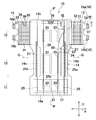
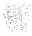
本開示に係る使い捨て着用物品の一例として示す、第1実施形態に係る使い捨ておむつの斜視図。
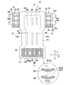
おむつを肌対向面側から視た一部破断展開平面図。
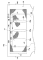
おむつを非肌対向面側から視た展開平面図。
図2のIV-IV線に沿う断面図。
(a)フック要素の側面図。(b)図3に示す、V(b)-V(b)線に沿う断面図。
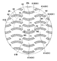
おむつを非肌対向面から視た後ウエスト域の平面図。
図6に示す、VII線で囲まれた領域の拡大図。
図1のVIII-VIII線に沿う断面図。
変形例1に係るおむつの図1と同様の斜視図。
変形例2に係るおむつの図3と同様の展開平面図。
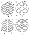
(a)~(d)他の変形例における、図7と同様の拡大図。
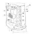
第2実施形態に係るおむつの図1と同様の斜視図。
第2実施形態に係るおむつの図2と同様の一部判断展開平面図。
第2実施形態に係るおむつの図4と同様の断面図。
<第1実施形態>
下記の実施の形態は、本発明の一例である図1~図8に示す、第1実施形態に係る使い捨ておむつ10に関し、発明の不可欠な構成ばかりではなく、選択的及び好ましい構成を含む。図2及び3において、後述する各弾性体は、その収縮力に抗して、横方向X及び縦方向Yへの収縮力により、各弾性体が取り付けられた部材に生じたギャザーが自然な視覚によって実質的に無くなっているように見える程度にまで伸長された状態にある。
下記の実施の形態は、本発明の一例である図1~図8に示す、第1実施形態に係る使い捨ておむつ10に関し、発明の不可欠な構成ばかりではなく、選択的及び好ましい構成を含む。図2及び3において、後述する各弾性体は、その収縮力に抗して、横方向X及び縦方向Yへの収縮力により、各弾性体が取り付けられた部材に生じたギャザーが自然な視覚によって実質的に無くなっているように見える程度にまで伸長された状態にある。
図1~図3を参照すると、本発明に係る使い捨て着用物品の一例である使い捨てのおむつ10は、縦方向Y及びそれに交差する横方向Xと、肌対向面及びその反対側の非肌対向面と、横方向Xの長さ寸法を二等分する縦軸Pと、縦方向Yの長さ寸法を二等分する横軸Qとを有し、縦軸Pに関してほぼ対称であり、前ウエスト域11と、後ウエスト域12と、前ウエスト域11および後ウエスト域12の間に位置するクロッチ域13とを含む。
おむつ10は、ベース形態をなすおむつ本体14と、おむつ本体14の後ウエスト域12の両側部に備えられた一対のサイドパネル15とを含む。おむつ本体14は、クロッチ域13を画定する両側縁部が凹曲状を有している。おむつ本体14の前後ウエスト域11,12は、サイドパネル15に配置されたファスナ部16と、前ウエスト域11に位置するターゲットシート17とによって、連結及び分離可能に構成されている。
<おむつ本体>
おむつ本体14は、縦方向Yにおいて離間対向する前後端縁14a,14bと、横方向Xにおいて離間対向する両側縁14c,14dとを有し、肌対向面に位置する透液性の内面シート21と、非肌対向面に位置する不透液性の外面シート22と、内外面シート21,22の間に位置する吸収性コア23と、吸収性コア23と外面シート22との間に位置し、少なくとも吸収性コア23の底面全体を覆う難透液性又は不透液性の防漏シート24とを含む。内面シート21の肌対向面側には、横方向Xに離間し縦方向Yへ延びる一対のバリアカフシート25が配置されている。前ウエスト域11において、外面シート22の非肌対向面側には、ファスナ部16が係脱可能なターゲットシート17が配置されている。
おむつ本体14は、縦方向Yにおいて離間対向する前後端縁14a,14bと、横方向Xにおいて離間対向する両側縁14c,14dとを有し、肌対向面に位置する透液性の内面シート21と、非肌対向面に位置する不透液性の外面シート22と、内外面シート21,22の間に位置する吸収性コア23と、吸収性コア23と外面シート22との間に位置し、少なくとも吸収性コア23の底面全体を覆う難透液性又は不透液性の防漏シート24とを含む。内面シート21の肌対向面側には、横方向Xに離間し縦方向Yへ延びる一対のバリアカフシート25が配置されている。前ウエスト域11において、外面シート22の非肌対向面側には、ファスナ部16が係脱可能なターゲットシート17が配置されている。
内面シート21は、例えば、質量が約10~35g/m2、好ましくは約13~23g/m2の親水処理した疎水性のスパンボンド繊維不織布またはポイントボンド繊維不織布から形成されていることが好ましい。外面シート22は、おむつ本体14の外形を形成しており、質量が約10~30g/m2、好ましくは約13~24g/m2の疎水性のスパンボンド・メルトブローン・スパンボンド(以下SMSとする)繊維不織布またはスパンボンド繊維不織布から形成されていることが好ましい。防漏シート24は、難透液性、好ましくは、不透液性かつ透湿性のプラスチックフィルムを用いることができる。
吸収性コア23は、木材フラッフパルプ、高吸収性ポリマー粒子、またはこれらの混合物を用いることができる。また、図示していないが、吸収性コア23は、透液性及び液拡散性を有するシート、例えば、ティッシュペーパ等から形成されたコアカバーシートによって全体が包被されている。吸収性コア23は、少なくともクロッチ域13に位置していればよく、本実施形態では、クロッチ域13から前後ウエスト域11,12へと延在している。吸収性コア23の肌対向面側には、縦方向Yへ延びる複数条の変形誘導部29が形成されている。
変形誘導部29は、肌対向面側から非肌対向面側へ向かって凹んだ凹条溝であって、吸収性コア23の厚さ寸法が他の部分に比して小さくなっている。変形誘導部29は、前後ウエスト域11,12及びクロッチ域13のそれぞれにおいて、横方向Xにおいて所与寸法離間して複数配置されており、また、縦方向Yにおいて並んで配置されている。吸収性コア23の縦方向Yの寸法が比較的に大きくなり、着用状態において着用者の身体形状に沿って変形し難いところ、縦方向Yへ延びる凹条溝からなる変形誘導部29をおむつ10全体に配置することによって、吸収性コア23を着用者の身体形状に沿うように変形させることができる。また、変形誘導部29は、吸収した体液を吸収性コア23の全体に拡散させるための誘導溝としての機能も有する。
変形誘導部29は、吸収性コア23の一部を取り除く、または、加圧することによって形成された有底の凹条溝であって、加圧して形成された場合には、吸収性コア23の他の領域に比して高密度かつ高剛性の領域となる。変形誘導部29は、後記の本発明の効果を奏する限りにおいて、有底の凹条溝ではなく、吸収性コア23が存在しない、スリットであってもよいし、また、全体的に縦方向Yへ直状に延びるものではなく、その一部が湾曲していてもよい。
図2を参照すると、後ウエスト域12において、内外面シート21,22の間であって吸収性コア23の縦方向Y外側には、横方向Xに延びる複数条のウエスト弾性体26が伸長状態で取り付けられる。また、防漏シート24の肌対向面側であって、吸収性コア23の横方向X外側には、レッグ弾性体27が取り付けられる。レッグ弾性体27は、防漏シート24とバリアカフシート25との間において、図示しないホットメルト接着剤等の公知の接合手段によって接合される。レッグ弾性体27は、クロッチ域13から前後ウエスト域11,12まで延びている。レッグ弾性体27としては、縦方向Yへ伸長状態で収縮可能に取り付けられた複数本のストリング状またはストランド状の弾性体を用いることができる。レッグ弾性体27によって、吸収性コア23の横方向Xの両外側域には、ガスケット機能を有する弾性サイドフラップが形成される。
バリアカフシート25は、例えば、質量が約10~30g/m2の疎水性のSMS繊維不織布またはスパンボンド繊維不織布を用いることができる。バリアカフシート25は、内面シート21の肌対向面に固定された、縦方向Yにおいて離間対向する前固定部及び後固定部と、縦方向Yへ延びる固定側部(近位部)25aと、固定側部25aの横方向Xの内側に位置するスリーブ状の自由側縁部(遠位縁部)25bとを有する。自由側縁部25b内には、ストリング状又はストランド状の弾性部材からなり、縦方向Yへ延びるカフ弾性体28が伸長状態で収縮可能に取り付けられる。カフ弾性体28が収縮することによって、自由側縁部25bが内面シート21から着用者の身体側へ離間し、排泄物の横漏れを防止するための一対の防漏カフスが形成される。
<サイドパネル>
図2~図4を参照すると、おむつ本体14の後ウエスト域12には、その両側縁部に一対のサイドパネル15が取り付けられる。サイドパネル15は、弾性伸縮性を有する弾性パネル31と、弾性パネル31とおむつ本体14とを連結するための連結シート32と、弾性パネル31から横方向Xの外側に延出するファスナ部16を備えたタブシート33とを含む。
図2~図4を参照すると、おむつ本体14の後ウエスト域12には、その両側縁部に一対のサイドパネル15が取り付けられる。サイドパネル15は、弾性伸縮性を有する弾性パネル31と、弾性パネル31とおむつ本体14とを連結するための連結シート32と、弾性パネル31から横方向Xの外側に延出するファスナ部16を備えたタブシート33とを含む。
弾性パネル31は、肌対向面に位置する第1シート34と、非肌対向面に位置する第2シート35と、第1及び第2シート34,35との間に取り付けられた横方向Xに延びる複数条のサイド弾性体36とを含む。第1及び第2シート34,35は、矩形状であって例えば、質量が約10~30g/m2のSMS繊維不織布を用いることができる。サイド弾性体36としては、横方向Xへ伸長状態で収縮可能に取り付けられた複数本のストリング状またはストランド状の弾性体を用いることができる。弾性パネル31は、非伸縮性の連結シート32を介しておむつ本体14の後ウエスト域12に接合される。具体的には、連結シート32の横方向Xにおける内側縁部が、外面シート22と、内面シート21又はバリアカフシート25との間に配置されて、互いに接合され、連結シート32の外側縁部が、第2シート35の非肌対向面に接合される。連結シート32は、例えば、質量が約40~60g/m2の疎水性のスパンボンド繊維不織布、SMS繊維不織布等を用いることができる。また、サイドパネル15(弾性パネル31)は、サイド弾性体36の収縮力の作用する弾性区域31Aと、その収縮力が作用しない非弾性域とを有する。
タブシート33は、肌対向面に位置する第1タブシート37と、非肌対向面に位置する第2タブシート38とを含む。第1及び第2タブシート37,38は、縦方向Yへ延びるとともに、横方向X外側に突出して縦方向Yへ互いに離間する複数のタブ39が形成されており、タブ39の肌対向面側には、ファスナ部16がそれぞれ配置される。従って、ファスナ部16は、縦方向Yへ離間して複数配置され、本実施形態ではウエスト開口側に位置する外側ファスナ部16aとクロッチ域13側に位置する内側ファスナ部16bとを含む。弾性区域31Aの横方向Xにおける外側縁部は、第1及び第2タブシート37,38の間に配置されて、互いに接合される。第1及び第2タブシート37,38としては、例えば、質量が約40~60g/m2のスパンボンド繊維不織布、SMS繊維不織布等を用いることができる。サイドパネル15を構成する各シート間における接合には、図示しないホットメルト接着剤等の公知の接合手段を用いることができる。
図5(a)を参照すると、ファスナ部16は、タブシート33に接合される基材シート40と、複数のフック41とを含み、フック41は、基材シート40から起立する軸部42と、軸部42の先端に形成された頭部43とを有する。ファスナ部16の材料としては、例えば、ポリエチレン、ポリプロピレン等のオレフィン系の材料や、ポリエステル系の材料等を用いることができる。
軸部42は、基材シート40からほぼ垂直に延び、頭部43は、軸線が基材シート40の表面とほぼ平行となるように形成されている。頭部43は、軸部42の先端の直径d1よりも大きなフック径d2(頭部の長手方向の寸法)を有し、本実施形態において直径d1は200μmであり、フック径d2は約410μmである。フック41の高さ寸法hは、後述するターゲットシート17の外層部分60の厚さ寸法t1の約70~100%であることが好ましい。ターゲットシート17の外層部分60を構成する後記のフィラメント60aの繊維径は、互いに隣り合うフック41の頭部43の離間寸法R1よりも小さく、頭部43が繊維間に入り込むことにより、ファスナ部16とターゲット部である多数の凸部61とは係脱可能に係合する。なお、本実施形態においては、軸部42は基端から先端に向かって先細状に延びているが、ほぼ同径の円筒状であってもよく、また、頭部43もターゲットシート17に係合される限りにおいて、他の公知の形状を採用することができる。
<ターゲットシート>
図2及び図3を参照すると、おむつ本体14の前ウエスト域12の非肌対向面側には、ターゲットシート17が配置されている。ターゲットシート17は、おむつ本体14の非肌対向面に固定された内層部分(内層シート)50と、ターゲットシート17の外面を形成する外層部分(外側シート)60とを積層して形成された複合シートから形成される。内外層部分50,60は、熱融着繊維を含む各種公知の製法によって製造された繊維不織布シートから形成されており、内層部分50としては、例えば、フィラメント繊維(長繊維)50aを含む質量20~30g/m2のメルトブローン繊維不織布やエアスルー繊維不織布、外層部分60としては、例えば、ステープル繊維(短繊維)60aを含む質量10~20g/m2のスパンボンド繊維不織布等から形成することができる。内層部分50はフィラメント繊維50a、外層部分60はステープル繊維60aを含むことによって、フック41と係合したときに内層部分50における毛羽立ちを抑制し、係脱を繰り返しても所定の係合強度を維持することができる。
図2及び図3を参照すると、おむつ本体14の前ウエスト域12の非肌対向面側には、ターゲットシート17が配置されている。ターゲットシート17は、おむつ本体14の非肌対向面に固定された内層部分(内層シート)50と、ターゲットシート17の外面を形成する外層部分(外側シート)60とを積層して形成された複合シートから形成される。内外層部分50,60は、熱融着繊維を含む各種公知の製法によって製造された繊維不織布シートから形成されており、内層部分50としては、例えば、フィラメント繊維(長繊維)50aを含む質量20~30g/m2のメルトブローン繊維不織布やエアスルー繊維不織布、外層部分60としては、例えば、ステープル繊維(短繊維)60aを含む質量10~20g/m2のスパンボンド繊維不織布等から形成することができる。内層部分50はフィラメント繊維50a、外層部分60はステープル繊維60aを含むことによって、フック41と係合したときに内層部分50における毛羽立ちを抑制し、係脱を繰り返しても所定の係合強度を維持することができる。
ターゲットシート17において、内層部分50におけるフィラメント繊維50aの平均繊維径は、約2.0~6.0μmである。外層部分60におけるステープル繊維60aの平均繊維径は、約10~30μmであって、内層部分50のフィラメント繊維50aの平均繊維径よりも大きくなっている。ターゲットシート17がかかる繊維構成を有することによって、ファスナ部16のフックが内層部分50のフィラメント繊維50aと係合され易くなる一方、外層部分60のステープル繊維60aは破断強度が比較的に高く、フックの係合操作を繰り返しても容易に破断せず、外層部分60が破断して係合強度が低下するのを抑制することができる。
図3を参照すると、ターゲットシート17は、接合域を介しておいておむつ本体14の非肌対向面に接合されており、接合域は、ホットメルト接着剤等の公知の接合手段を用いてターゲットシート17とおむつ本体14とが互いに接合された接合部45と、ターゲットシート17とおむつ本体14とが接合されていない非接合部46とを有する。非接合部46は、その周囲に位置する接合部45によって画定され、横方向Xへ離間して複数形成される。なお、図2において、説明の便宜上、接合部45には薄色のドットを付している。
図6及び図7を参照すると、ターゲットシート17は、その外面において、横方向Xへ連続的に延びる凸部(ターゲット部)61と、凸部61間に位置して横方向へ断続的に延びる凹部62とを有する。凹部62は、湾曲状であって、ターゲットシート17の外面に熱エンボス加工を施すことによって形成されたデボス部であって、内層部分50のフィラメント繊維50aと外層部分60のステープル繊維60aとが互いに熱溶着されている。内層部分50と外層部分60とは、それらの互いに対向する面に塗布されたホットメルト接着剤を介して接合されておらず、複数の凹部62においてのみシールされている。
凸部61は、複数の凹部62を囲むように配置されており、横方向Xへゆるやかに連続してウエーブ状に延びる複数の連続部分61Aと、連続部分61Aの形状に沿うように配置された複数の凹部62間に位置する複数の分断部分(ブリッジ)61Bとを有する。複数の連続部分61Aは、ターゲットシート17の両側縁17c,17d間において横方向Xへ連続して延びている。図示例では、凹部62は、分断部分61Bによって分断されていることから、横方向Xへ断続的に延びているが、後記の本発明の効果を奏する限りにおいて、複数の凹部62がつながって連続的に横方向Xへ延びていてもよい。
ターゲットシート17の外面形状における各種寸法についていえば、縦方向Yの寸法L1が100~150mm、凸部61の連続部分61Aの幅寸法W1は1.0~5.0mm、分断部分61Bの幅寸法W2は1.0~3.0mm、凹部62の長さ寸法L3は、1.5~15.0mm、幅寸法W3は0.2~0.8mm、その曲率は65~80度である。凹部62では、熱エンボス加工によって内層部分50のフィラメント繊維50aと外層部分60のステープル繊維60aとが熱融着されており、ファスナ部16が係止されない非係止領域を形成している。このように係止領域(凸部61)の間に非係止領域(凹部62)を形成することによって、ファスナ部16をターゲットシート17から剥離する際、剥離力によって繊維が毛羽立ってループ部分が変形することを抑えることができる。凹部62の外面全体の面積に対する凹部62の面積率は、35~50%である。
ターゲットシート17と、吸収性コア23の縦方向Yへ延びる複数の変形誘導部29とは、おむつ10の平面視において互いに重なって位置している。変形誘導部29は、縦方向Yにおいて互いに対向する内外端部29a,29bを有し、内端部29aはターゲットシート17の内端縁17aの縦方向Yの外側に位置しており、外端部29bはターゲットシート17の外端縁17bの縦方向Yの内側に位置しており、変形誘導部29全体がターゲットシート17の存在域に位置している。
おむつ10の着用状態であって、ファスナ部がターゲットシート17に係止された状態において、変形誘導部29全体がターゲットシート17内に位置していることから、ファスナ部16の一部が変形誘導部29と平面視において重なって位置している。
図8を参照すると、おむつ10を着用する際には、着用者又は着用補助者が、タブシート33を摘持して前ウエスト域11側へ引っ張り、指先でファスナ部16の外面を抑えてターゲットシート17の外面に押し当てて凸部61に係止することが必要となる。変形誘導部29は、吸収性コア23の厚さ寸法が他の部分に比して小さい凹条溝であるから、ターゲットシート17のうちの変形誘導部29上に位置する所定領域70が吸収性コア23の底面23dから離間した状態となり変形し易いので、ファスナ部16を比較的に強い力で押し当てても、所定領域70が着用者の腹部2へ向かって変形してフック41を凸部61に係合させることができないおそれがある。また、さらに強い力でファスナ部16をターゲットシート17に押し当てようとすると、着用者の腹部2を局所的に圧迫して不快感を与えるおそれがある。また、かかる事態を避けるために、変形誘導部29と平面視において重ならない位置にファスナ部16を係止させる場合には、着用者の腹部2を必要以上に締め付け又は緩く締め付けることになるので、おむつ10のフィット性が低下するおそれがある。
本実施形態に係るおむつ10においては、ターゲットシート17の外面において、縦方向へ延びる凹条溝からなる変形誘導部29に対してそれと交差又は直交するように横方向Xへ連続して延びる凸部61が形成されていることによって、ターゲットシート17全体の横方向Xにおける剛性が比較的に高くなっている。具体的には、凸部61の複数の連続部分61Aは、ターゲットシート17の横方向Xの寸法全域に連続的に延びているので、複数の変形誘導部29全体を横断している。そのため、ファスナ部16が変形誘導部29と平面視と重なって位置するときに、それを凸部61に係止するためにファスナ部16を押圧し、所定領域70にその押圧する力が作用する場合であっても、所定領域70が着用者の腹部2に向かって変形することを抑制することができる。
ターゲットシート17の複数の凹部62は、曲線状であって、変形誘導部29と交差するように横方向Xへ延びている。例えば、フック41の非係止域である凹部62が凸部61と交差するように縦方向Yへ延びている場合には、ターゲットシート17の所定領域70が横方向Xにおいて凹凸を繰り返した外面形状を有し、フック41が凸部61に係止され難くなるおそれがある。本実施形態においては、凹部62が凸部61と同様に、横方向Xへ延びていることによって、ターゲットシート17の外面を平坦にすることができる。
また、凹部62は、内層部分50のフィラメント繊維50aと外層部分60のステープル繊維60aとが熱溶着されたシールラインであるから比較的に剛性が高くなっている。したがって、複数の凹部62が横方向Xへ延びていることによって、凸部61とともに、ターゲットシート17の横方向Xにおける剛性の向上に寄与するといえる。凹部62は、横方向Xへ断続的に曲状に延びていることから、それが直状を有する場合に比して、縦方向Yへ直状に延びる変形誘導部29と平面視において重なる面積が大きくなり、所定領域70の変形をより効果的に抑制しうる。
再び、図7を参照すると、外層部分60のステープル繊維60aは、縦方向Yに沿った繊維配向性を有しており、凸部61の連続部分61Aでは、縦方向Yの寸法が大きい幅広部71と、縦方向Yの寸法が小さい幅狭部72とが横方向Xにおいて(または、その長さ方向において)複数並んでいる。ステープル繊維60aが縦方向Yに沿った繊維配向性を有することによって、それが横方向Xに沿った繊維配向を有する場合に比して、ターゲットシート17の横方向Xに対する剛性が高くなる。また、凸部61の縦方向Yの寸法(幅寸法)W1がほぼ均一の場合には、ファスナ部16の引っ張り方向(横方向X)の力が比較的に強く加えられたときに、ループを形成するフィラメント繊維50aとステープル繊維60aとが一様に切れて、ファスナ部16による係止を繰り返し行うことができなくなるおそれがあるが、幅広部71と幅狭部72とが存在することによって、引っ張り方向へ連続してそれらが破断するのを抑制することができる。
再び、図2を参照すると、既述のとおり、ターゲットシート17は、おむつ本体14の非肌対向面側に接合域を介して接合されており、接合域は接合部45と、接合部45に囲まれた複数の非接合部46とを有する。ファスナ部16がターゲットシート17に係止された状態において、ターゲットシート17の全面がおむつ本体14に接合されている場合には、タブ39の動きにターゲットシート17が追従できず、係合が解除されてしまうおそれがあるが、ターゲットシート17のうちの非接合部46の存在域とファスナ部16とが係合されたときには、該存在域がおむつ本体14から離間してファスナ部16の動きに応じて変形しうるので、ファスナ部16の係合が解除されるのを防止することができる。
図示していないが、おむつ10の着用状態において、サイドパネル15はターゲットシート17と互いに重なり合っており、弾性パネル31の肌対向面とターゲットシート17の外面とが当接している。図4を参照すると、弾性パネル31は、収縮状態において横方向へ起伏を繰り返す凹凸状であって、ファスナ部16が凸部61に係止された状態において、凹凸状の弾性パネル31がターゲットシート17の外面に当接することによって、弾性区域31Aの当接面においては平坦状の非弾性区域の当接面よりも高い摩擦抵抗が生じる。それによって、サイドパネル15にファスナ部16の係合を解除するような力が加えられても、係合が解除されるのを抑制することができる。また、凹凸状の弾性パネル31の内面側には、前ウエスト域11が位置することによって、表面が凹凸した弾性パネル31が着用者の肌に直接触れ難く又は触れることはなく、表面が平滑な前ウエスト域11が肌に当接されるので、肌触りが良好となる。
(変形例1)
図9は、変形例1における図1と同様の、着用状態におけるおむつ10の斜視図である。本変形例においては、ターゲットシート17は、後ウエスト域12における他の領域と識別可能となるように着色されている。着色は、識別可能な限りにおいて、赤色、青色、黄色等の公知の色彩を用いることができる。なお、図10においては、着色されていることが分かるように、ターゲットシート17の外面に薄色のドットを付している。
図9は、変形例1における図1と同様の、着用状態におけるおむつ10の斜視図である。本変形例においては、ターゲットシート17は、後ウエスト域12における他の領域と識別可能となるように着色されている。着色は、識別可能な限りにおいて、赤色、青色、黄色等の公知の色彩を用いることができる。なお、図10においては、着色されていることが分かるように、ターゲットシート17の外面に薄色のドットを付している。
また、サイドパネル15における、内側ファスナ部16bの内端縁80から外側ファスナ部16aの外端縁81までの離間寸法(縦方向Yの寸法)L4は、ターゲットシート17の縦方向Yの寸法L1よりも大きくなっている。具体的には、ターゲットシート17の縦方向Yの寸法L1が約100~150mmであるのに対し、離間寸法L4は、約160~200mmである。両寸法L1,L4がかかる相関関係を有することによって、おむつ10を着用するときには、ファスナ部16a,16bをターゲットシート17に係止するときには、外側ファスナ部16aを斜め下方へ引っ張って係止し、かつ、内側ファスナ部16bを斜め上方に引っ張って係止することになるので、ウエスト開口側が下方へ引っ張られるとともにレッグ開口側が上方へ引っ張られた態様となる。それによって、ウエスト開口縁部及びレッグ開口縁部のフィット性が向上し、着用状態におけるおむつ10の位置ずれ及び排泄物の漏れを防止することができる。図示していないが、ターゲットシート17の縦方向Yの寸法が比較的に小さいことから、変形誘導部29の外端部29bがターゲットシート17の外端縁よりも縦方向Yの外側に位置する。かかる態様において、変形誘導部29が吸収性コア23の存在しないスリットである場合には、ターゲットシート17のうちの変形誘導部29と存在域において通気性が向上し、ターゲットシート17が繊維不織布から形成されていることと相俟って、おむつ10内部の蒸れを効果的に抑制することができる。
(変形例2)
図10は、他の変形例における図3と同様図である。図10を参照すると、本変形例においては、おむつ本体14の外面に縦方向Yへ断続的に延びる、複数の表示要素91aから形成された第1表示部91が配置されている。第1表示部91は、横方向Xにおいて離間して複数配置されており、おむつ本体14の前端縁14aから後端縁14bまでその縦寸法のほぼ全域に延在している。また、ターゲットシート17の外面には、縦方向Yへライン状に延び、かつ、横方向Xにおいて互いに離間した複数の第2表示部92が配置されている。第1表示部91と第2表示部92とは、縦方向Yにおいて並んで配置されている。第1及び第2表示部91,92がこのような配置パターンを有することによって、おむつ10の製造工程において、ターゲットシート17をおむつ本体14に対して所定の位置に配置することができる。このように、第1及び第2表示部91,92が、おむつ10の製造工程におけるターゲットシート17の位置決めとして機能することのほかに、おむつ10の背面における外観の意匠性に優れるとともに、おむつ10の着用状態においては、第2表示部92は、着用者のサイズを表示する機能を有する。なお、第1表示部91を構成する表示要素91aは、図示例のような十字状のほかに、円形や矩形、星形等の各種公知の図柄を採用することができる。
図10は、他の変形例における図3と同様図である。図10を参照すると、本変形例においては、おむつ本体14の外面に縦方向Yへ断続的に延びる、複数の表示要素91aから形成された第1表示部91が配置されている。第1表示部91は、横方向Xにおいて離間して複数配置されており、おむつ本体14の前端縁14aから後端縁14bまでその縦寸法のほぼ全域に延在している。また、ターゲットシート17の外面には、縦方向Yへライン状に延び、かつ、横方向Xにおいて互いに離間した複数の第2表示部92が配置されている。第1表示部91と第2表示部92とは、縦方向Yにおいて並んで配置されている。第1及び第2表示部91,92がこのような配置パターンを有することによって、おむつ10の製造工程において、ターゲットシート17をおむつ本体14に対して所定の位置に配置することができる。このように、第1及び第2表示部91,92が、おむつ10の製造工程におけるターゲットシート17の位置決めとして機能することのほかに、おむつ10の背面における外観の意匠性に優れるとともに、おむつ10の着用状態においては、第2表示部92は、着用者のサイズを表示する機能を有する。なお、第1表示部91を構成する表示要素91aは、図示例のような十字状のほかに、円形や矩形、星形等の各種公知の図柄を採用することができる。
(他の変形例)
図11(a)~(d)は、本発明のおむつ10の変形例の一例を示す、図7と同様の拡大図である。図11(a)~(d)は、ターゲットシート17の外面における凹凸模様を示したものであって、図11(a)は、横方向へ連続してウエーブ状に延びる複数の凸部61とその間において連続してウエーブ状に延びる複数の凹部62とを有する模様、図11(b)は、縦方向Yの内側へ凸曲した複数の凹部62が縦方向Yに並び、かつ、その縦に並んだ複数の列が横方向Xにおいて離間しており、凸部61が複数の凹部62を囲むように位置する模様、図11(c)は、縦方向Yの内側へ凸曲した複数の凹部62とそれを囲むように位置する凸部61とから形成された模様、図11(d)は、横方向Xへウエーブ状に延びる複数の凹部62と、凹部62間に位置する複数の凸部61とを有し、凸部61は、縦方向Yにおいて対向する両側縁93,94が横方向Xにおいて接近と離間を繰り返した形状をなす模様である。図11(c),(d)のように、第1実施形態のパターンよりもより明確に、凸部61が離間と接近を横方向Xにおいて交互に繰り返すことによって、凹部62において縦方向Yへ配向された繊維の長さが不均一となり、ファスナ部16が係合された状態で横方向Xへ引っ張る力が加えられたとしても繊維が一様に切断されず、ファスナ部16との係合を解除した後においても表面が毛羽立ち難く、繰り返し止着操作をするときにおいても一定の係合強度を維持することができる。これらの複数の凹凸模様のいずれにおいても、本実施形態に係るおむつ10の特徴構成を備える限りにおいて、図7に示す凹凸模様と同様の技術的効果を奏することができる。
図11(a)~(d)は、本発明のおむつ10の変形例の一例を示す、図7と同様の拡大図である。図11(a)~(d)は、ターゲットシート17の外面における凹凸模様を示したものであって、図11(a)は、横方向へ連続してウエーブ状に延びる複数の凸部61とその間において連続してウエーブ状に延びる複数の凹部62とを有する模様、図11(b)は、縦方向Yの内側へ凸曲した複数の凹部62が縦方向Yに並び、かつ、その縦に並んだ複数の列が横方向Xにおいて離間しており、凸部61が複数の凹部62を囲むように位置する模様、図11(c)は、縦方向Yの内側へ凸曲した複数の凹部62とそれを囲むように位置する凸部61とから形成された模様、図11(d)は、横方向Xへウエーブ状に延びる複数の凹部62と、凹部62間に位置する複数の凸部61とを有し、凸部61は、縦方向Yにおいて対向する両側縁93,94が横方向Xにおいて接近と離間を繰り返した形状をなす模様である。図11(c),(d)のように、第1実施形態のパターンよりもより明確に、凸部61が離間と接近を横方向Xにおいて交互に繰り返すことによって、凹部62において縦方向Yへ配向された繊維の長さが不均一となり、ファスナ部16が係合された状態で横方向Xへ引っ張る力が加えられたとしても繊維が一様に切断されず、ファスナ部16との係合を解除した後においても表面が毛羽立ち難く、繰り返し止着操作をするときにおいても一定の係合強度を維持することができる。これらの複数の凹凸模様のいずれにおいても、本実施形態に係るおむつ10の特徴構成を備える限りにおいて、図7に示す凹凸模様と同様の技術的効果を奏することができる。
<第2実施形態>
図12は、第2実施形態に係るおむつ10の図1と同様の斜視図、図13は、第2実施形態に係るおむつ10の図2と同様の平面図、図14は、第2実施形態に係るおむつ10の図4と同様の断面図である。本実施形態に係るおむつ10の基本的構成は、第1実施形態のそれと同様であるので、相違する点についてのみ以下に説明する。
図12は、第2実施形態に係るおむつ10の図1と同様の斜視図、図13は、第2実施形態に係るおむつ10の図2と同様の平面図、図14は、第2実施形態に係るおむつ10の図4と同様の断面図である。本実施形態に係るおむつ10の基本的構成は、第1実施形態のそれと同様であるので、相違する点についてのみ以下に説明する。
図12~図14を参照すると、本実施形態においては、連結シート32のうちのおむつ本体14から横方向Xの外側へ延出する部分、おむつ本体14と弾性パネル31の弾性区域31Aとの横方向Xにおける離間部分30の横方向Xの寸法W4が、第1実施形態のそれよりも大きくなっている。具体的には、第1実施形態の離間部分30の横方向Xの寸法が約5~10mmであるのに対し、本実施形態の離間部分30の横方向Xの寸法W4は、約10~30mmである。
図12を参照すると、離間部分30の横方向Xの寸法が比較的に大きいことから、弾性区域31A全体が前ウエスト域11と重なるように位置している。表面が凹凸した弾性パネル31全体が着用者の肌に直接触れ難く又は触れることはなく、表面が平滑な前ウエスト域11が肌に当接されるので、肌触りが良好となる。
また、例えば、おむつ10を展開させて、仰臥状態の着用者の背面側に配置した状態において、後ウエスト域12の凹凸状の弾性区域31Aが着用者の身体に触れるときには肌を刺激して違和感を与えたり、弾性区域31Aが抑えられた状態で伸長して装着操作がし難くなるおそれがある。特に、寝たきりの高齢者の場合には、弾性区域31Aが直接肌に触れることによって褥瘡の原因となるおそれがある。本実施形態においては、後ウエスト域12の横方向Xの寸法が前ウエスト域11のそれと比較して大きく形成することによって、弾性区域31Aが寝臥状態の着用者の身体の外側に位置した状態となるので、弾性区域31Aが身体の下に位置して肌に直接触れることはなく、かかる違和感を与えることはない。また、着用補助者が弾性区域31Aを把持してサイドパネル15を前ウエスト域11側へ引っ張ろうとしても、弾性区域31A自体が伸長されて上手く引っ張ることができないが、比較的に大きく形成された離間部分30を把持することによって、サイドパネル15を前ウエスト域11側に容易に引っ張ることができる。
本実施形態において、連結シート32から形成された離間部分30の質量M1と、外面シート22とバリアカフシート25とから形成された内側積層部分85の質量(両シート22,25の質量を加算したもの)M2と、第1シート34と第2シート35とから形成された外側積層部分86の質量(両シート34,35の質量を加算したもの)M3とを比較した場合、各質量の大きさの相関関係は、M1≧M2=M3となっている。具体的には、連結シート32の質量は30~50g/m2であって、外面シート22とバリアカフシート25との質量は、それぞれ、10~20g/m2、弾性パネル31の内層シート34と外層シート35との質量は、それぞれ、10~20g/m2である。
内側積層部分85と外側積層部分86との間に位置する単層構造の離間部分30の質量が比較的に小さく、かつ、厚さ寸法が内外積層部分85,86のそれよりも小さい場合には、離間部分30において局所的に剛性が小さくなって剛性変化点として作用し、着用状態において、離間部分30に縦皺が形成され、サイドパネル15が身体に沿った曲状に変形されず、一部が屈曲して身体から一部が離間したような状態となるおそれがある。また、着用者が寝臥状態の場合、離間部分30が身体の下に位置したときに、厚さ寸法の変化によって違和感を与えるおそれがある。本実施形態においては、離間部分30の質量が、内外側積層部分85,86の総質量よりも高くなっていることから、急激な剛性の変化や厚さ寸法の違いが生じることはなく、かかる不利益が生じるのを抑制することができる。
また、サイドパネル15は、複数のシート部材及び弾性部材から形成されていることによって、それに当接される身体部分が蒸れやすくなるおそれがあるところ、単層構造からなる離間部分30が位置することによって通気性が良くなり、蒸れを抑制することができる。また、離間部分30は、内外側積層部分85,86に比して透過性に優れ、肌が外部から視認されることによって通気性の良好なイメージを与えることができる。さらに、連結シート32が比較的に高い剛性を有することによって、着用状態において縦皺が形成されることなく曲状に折れ曲がってしてサイドパネル15を身体形状に沿うように変形させることができる。
図14に示す拡大図を参照すると、バリアカフシート25の側縁部が折曲された折曲部分25aが形成されている。このように、内側積層部分85のうちの離間部分30に隣接する部位が、内側積層部分85の他の部分よりも積層されたシート枚数が多く剛性が高くなっていることから、着用時に、折曲部分25a近傍を把持することによって、内側積層部分85の他の部分を把持するよりもサイドパネル15を安定的に引っ張って拡げることができる。なお、本実施形態と異なり、バリアカフシート25ではなく、外面シート22の側縁部を折曲することによって同様の効果を奏することができる。
本実施形態では、ファスナ部16が後ウエスト域12に配置されているが、前ウエスト域11に配置されて、後ウエスト域12にターゲットシート17が配置されていてもよい。また、上述したおむつ10は、前後ウエスト域11,12が分離しており、ファスナ部16によって前後ウエスト域11,12を連結する構成であるが、前後ウエスト域11,12が両側部において互いに連結されたパンツ型のおむつにおいて、外面シート22に係脱可能なサイズ調整用のファスナ部16を備えた構成であってもよい。
本発明の使い捨て着用物品を構成する各構成部材には、明細書に記載されている材料のほかに、この種の物品において通常用いられている各種公知の材料を制限なく用いることができる。また、明細書及び特許請求の範囲において、「第1」及び「第2」等の用語は、同様の要素、位置等を単に区別するために用いられる。
10 おむつ(使い捨て着用物品)
11 前ウエスト域(第1ウエスト域又は第2ウエスト域)
12 後ウエスト域(第1ウエスト域又は第2ウエスト域)
13 クロッチ域
14 おむつ本体
15 サイドパネル
16 ファスナ部
16a 外側ファスナ部
16b 内側ファスナ部
17 ターゲットシート
23 吸収性コア
29 変形誘導部
31 弾性パネル
32 連結シート
31A 弾性区域
45 接合部
48 非接合部
50 内層部分
50a 内層部分の長繊維(フィラメント繊維)
60a 外層部分の短繊維(ステープル繊維)
61 凸部
62 凹部
71 凸部の幅広部
72 凸部の幅狭部
81 内側ファスナ部の内端縁
82 外側ファスナ部の外端縁
85 内側積層部分
86 外側積層部分
91 第1表示部
92 第2表示部
L4 連結シートの離間部分の横方向Xの寸法
X 横方向
Y 縦方向
11 前ウエスト域(第1ウエスト域又は第2ウエスト域)
12 後ウエスト域(第1ウエスト域又は第2ウエスト域)
13 クロッチ域
14 おむつ本体
15 サイドパネル
16 ファスナ部
16a 外側ファスナ部
16b 内側ファスナ部
17 ターゲットシート
23 吸収性コア
29 変形誘導部
31 弾性パネル
32 連結シート
31A 弾性区域
45 接合部
48 非接合部
50 内層部分
50a 内層部分の長繊維(フィラメント繊維)
60a 外層部分の短繊維(ステープル繊維)
61 凸部
62 凹部
71 凸部の幅広部
72 凸部の幅狭部
81 内側ファスナ部の内端縁
82 外側ファスナ部の外端縁
85 内側積層部分
86 外側積層部分
91 第1表示部
92 第2表示部
L4 連結シートの離間部分の横方向Xの寸法
X 横方向
Y 縦方向
Claims (13)
- 縦方向及び横方向と、肌対向面及び非肌対向面とを有し、前後ウエスト域の一方である第1ウエスト域と、前記前後ウエスト域の他方である第2ウエスト域と、前記第1及び第2ウエスト域間に位置するクロッチ域と、物品本体と、前記物品本体において前記クロッチ域から前記第1及び第2ウエスト域へ延びる吸収性コアと、前記第1ウエスト域の両側部に取り付けられて、前記第2ウエスト域に位置するターゲットシートに係脱可能な一対のファスナ部とを含む使い捨て着用物品において、
前記ターゲットシートの前記非肌対向面側には、凸部と凹部とが形成されており、
前記凹部は複数形成され、前記凸部は前記横方向へ連続して延びており、
前記吸収性コアは、平面視において前記凸部と交差するように前記縦方向へ延びる変形誘導部を有する前記着用物品。 - 前記凹部は、曲線状であって、前記変形誘導部と交差するように前記横方向へ延びる請求項1に記載の着用物品。
- 前記変形誘導部は、前記縦方向へ直線状に延びており、前記凹部は、前記横方向へ曲線状に延びる請求項2に記載の着用物品。
- 前記ターゲットシートは、前記非肌対向面を形成する外層部分と、前記肌対向面側に位置する内層部分とを有する繊維不織布層を含み、前記外層部分の平均繊維径は、前記内層部分の平均繊維径よりも大きい請求項1~3のいずれかに記載の着用物品。
- 前記外層部分は、前記縦方向に沿った繊維配向性を有しており、
前記凸部は、前記縦方向の寸法が大きい幅広部と、前記縦方向の寸法が小さい幅狭部とが前記横方向に複数並ぶ請求項4に記載の着用物品。 - 前記内層部分は長繊維からなり、前記外層部分は短繊維からなる請求項4又は5に記載の着用物品。
- 前記ターゲットシートは、前記物品本体の非肌対向面側に接合域を介して接合されており、前記接合域は、前記ターゲットシートと前記物品本体とが互いに接合された接合部と、前記ターゲットシートと前記物品本体とが接合されていない非接合部とを有する請求項1~6のいずれかに記載の着用物品。
- 前記ターゲットシートは、前記第2ウエスト域における他の領域と識別可能となるように着色されており、
前記ファスナ部は、前記縦方向において互いに離間する内側ファスナ部と外側ファスナ部とを有しており、前記縦方向における前記内側ファスナ部の内端縁から前記外側ファスナ部の外端縁までの寸法は、前記ターゲットシートの前記縦方向の寸法よりも大きい請求項1~7のいずれかに記載の着用物品。 - 前記物品本体は、外部から視認可能な第1表示部を有し、前記ターゲットシートは、外部から視認可能であって、かつ前記第1表示部に対応する位置合わせ用の第2表示部を有する請求項1~8のいずれかに記載の着用物品。
- 前記第1ウエスト域において、前記物品本体の両側縁から前記横方向の外側へ延出するサイドパネルをさらに有し、
前記サイドパネルは、前記横方向へ伸縮可能な弾性区域と、前記弾性区域の前記横方向の外側に位置し、かつ前記ファスナ部が配置された非弾性区域とを有し、
前記ファスナ部が前記ターゲットシートに係止した状態において、前記弾性区域と前記ターゲットシートとが互いに重なり合う請求項1~9のいずれかに記載の着用物品。 - 前記サイドパネルは、前記横方向へ伸縮可能な弾性区域を有する弾性パネルと、前記物品本体と前記弾性パネルとをつなぐ連結シートとを有し、前記連結シートは、前記物品本体から前記横方向の外側へ延出する離間部分を有し、前記離間部分の前記横方向の寸法が10~30mmである請求項1~10のいずれかに記載の着用物品。
- 前記離間部分は前記連結シートから形成された単層構造を有し、前記離間部分の前記横方向の内側に位置する、複数のシートから形成された内側積層部分と、前記離間部分の前記横方向の外側に位置する、複数のシートから形成された外側積層部分とをさらに有し、前記離間部分の単位面積当たりの質量が、前記内側積層部分の単位面積当たりの質量と前記外側積層部分の単位面積当たりの質量とのそれぞれよりも高い請求項11に記載の着用物品。
- 前記内側積層部分のうちの前記離間部分に隣接する部位のシートの積層数が、前記内側積層部分の他の部分のシートの積層数よりも多い請求項12に記載の着用物品。
Applications Claiming Priority (2)
| Application Number | Priority Date | Filing Date | Title |
|---|---|---|---|
| JP2015129323A JP5814485B1 (ja) | 2015-06-26 | 2015-06-26 | 使い捨て着用物品 |
| JP2015-129323 | 2015-06-26 |
Publications (1)
| Publication Number | Publication Date |
|---|---|
| WO2016208084A1 true WO2016208084A1 (ja) | 2016-12-29 |
Family
ID=54595904
Family Applications (1)
| Application Number | Title | Priority Date | Filing Date |
|---|---|---|---|
| PCT/JP2015/069209 Ceased WO2016208084A1 (ja) | 2015-06-26 | 2015-07-02 | 使い捨て着用物品 |
Country Status (2)
| Country | Link |
|---|---|
| JP (1) | JP5814485B1 (ja) |
| WO (1) | WO2016208084A1 (ja) |
Cited By (1)
| Publication number | Priority date | Publication date | Assignee | Title |
|---|---|---|---|---|
| TWI779058B (zh) * | 2017-10-04 | 2022-10-01 | 日商優你 嬌美股份有限公司 | 伸縮性薄片及吸收性物品 |
Families Citing this family (6)
| Publication number | Priority date | Publication date | Assignee | Title |
|---|---|---|---|---|
| JP6900940B2 (ja) * | 2016-06-30 | 2021-07-14 | 王子ホールディングス株式会社 | 吸収性物品 |
| JP6796500B2 (ja) | 2017-01-26 | 2020-12-09 | クラリオン株式会社 | 走行履歴変換方法、情報処理装置、情報システム |
| JP7126380B2 (ja) * | 2018-05-18 | 2022-08-26 | 花王株式会社 | 吸収性物品 |
| JP7187302B2 (ja) * | 2018-12-26 | 2022-12-12 | 花王株式会社 | 使い捨ておむつ |
| JP2021019728A (ja) * | 2019-07-25 | 2021-02-18 | 王子ホールディングス株式会社 | 吸収性物品 |
| JP2021019726A (ja) * | 2019-07-25 | 2021-02-18 | 王子ホールディングス株式会社 | 吸収性物品 |
Citations (8)
| Publication number | Priority date | Publication date | Assignee | Title |
|---|---|---|---|---|
| JP2001207369A (ja) * | 2000-01-28 | 2001-08-03 | Unitika Ltd | 面ファスナ雌材用不織布 |
| JP2012125594A (ja) * | 2007-04-17 | 2012-07-05 | Aplix Inc | 使い捨て物品又は衣類に使用されるループ・フック型ファスナー用のループ材料 |
| JP2012210482A (ja) * | 2012-08-06 | 2012-11-01 | Livedo Corporation | 使い捨ておむつ |
| JP2013519423A (ja) * | 2010-02-16 | 2013-05-30 | ファメッカニカ.データ エス.ピー.エー. | パンツとして装着できる衛生製品の製造方法および中間製品 |
| JP2013121428A (ja) * | 2011-12-09 | 2013-06-20 | Unicharm Corp | 吸収性物品 |
| JP2014054352A (ja) * | 2012-09-12 | 2014-03-27 | Kao Corp | 使い捨ておむつ |
| JP2014204756A (ja) * | 2013-04-10 | 2014-10-30 | ユニ・チャーム株式会社 | 使い捨ておむつ |
| JP5657162B1 (ja) * | 2014-07-31 | 2015-01-21 | ユニ・チャーム株式会社 | 吸収性物品 |
-
2015
- 2015-06-26 JP JP2015129323A patent/JP5814485B1/ja active Active
- 2015-07-02 WO PCT/JP2015/069209 patent/WO2016208084A1/ja not_active Ceased
Patent Citations (8)
| Publication number | Priority date | Publication date | Assignee | Title |
|---|---|---|---|---|
| JP2001207369A (ja) * | 2000-01-28 | 2001-08-03 | Unitika Ltd | 面ファスナ雌材用不織布 |
| JP2012125594A (ja) * | 2007-04-17 | 2012-07-05 | Aplix Inc | 使い捨て物品又は衣類に使用されるループ・フック型ファスナー用のループ材料 |
| JP2013519423A (ja) * | 2010-02-16 | 2013-05-30 | ファメッカニカ.データ エス.ピー.エー. | パンツとして装着できる衛生製品の製造方法および中間製品 |
| JP2013121428A (ja) * | 2011-12-09 | 2013-06-20 | Unicharm Corp | 吸収性物品 |
| JP2012210482A (ja) * | 2012-08-06 | 2012-11-01 | Livedo Corporation | 使い捨ておむつ |
| JP2014054352A (ja) * | 2012-09-12 | 2014-03-27 | Kao Corp | 使い捨ておむつ |
| JP2014204756A (ja) * | 2013-04-10 | 2014-10-30 | ユニ・チャーム株式会社 | 使い捨ておむつ |
| JP5657162B1 (ja) * | 2014-07-31 | 2015-01-21 | ユニ・チャーム株式会社 | 吸収性物品 |
Cited By (1)
| Publication number | Priority date | Publication date | Assignee | Title |
|---|---|---|---|---|
| TWI779058B (zh) * | 2017-10-04 | 2022-10-01 | 日商優你 嬌美股份有限公司 | 伸縮性薄片及吸收性物品 |
Also Published As
| Publication number | Publication date |
|---|---|
| JP5814485B1 (ja) | 2015-11-17 |
| JP2017012250A (ja) | 2017-01-19 |
Similar Documents
| Publication | Publication Date | Title |
|---|---|---|
| WO2016208084A1 (ja) | 使い捨て着用物品 | |
| JP5253064B2 (ja) | 使い捨ておむつ | |
| TWI533859B (zh) | Shorts are used for disposable items | |
| CN103237533B (zh) | 一次性尿布及其制造方法 | |
| JP5053954B2 (ja) | 止着テープ及びその製造方法、並びにテープ型おむつ | |
| JP2004024434A (ja) | 開放型の使い捨て着用物品 | |
| JP6316375B2 (ja) | 使い捨て着用物品 | |
| JP2012125483A (ja) | 使い捨ておむつ | |
| JP2011200336A (ja) | 止着テープおよびこの止着テープを備えた使い捨ておむつ | |
| EP3730110A1 (en) | Pants-type wearable article | |
| JP5777271B2 (ja) | 着用物品 | |
| KR20170027712A (ko) | 흡수성 물품 | |
| JP2014046049A (ja) | 使い捨てのパンツ型着用物品 | |
| JP2013198693A (ja) | テープ型おむつ及びテープ型おむつの製造方法 | |
| JP5282020B2 (ja) | テープ型使い捨ておむつ | |
| CN104619290A (zh) | 复合片材及其制造方法以及使用该复合片材的一次性穿戴物品 | |
| WO2017115538A1 (ja) | 吸収性物品 | |
| JP5814486B1 (ja) | 使い捨て着用物品 | |
| JP6278710B2 (ja) | 使い捨てのパンツ型着用物品 | |
| JP6712421B2 (ja) | テープタイプ使い捨ておむつ | |
| JP2001276119A (ja) | 使い捨て着用物品 | |
| JP5505469B2 (ja) | 止着テープ及びテープ型使い捨ておむつ | |
| JP2016104433A (ja) | テープ型おむつ及びテープ型おむつの製造方法 | |
| CN120693135B (zh) | 内裤型吸收性物品 | |
| JP7773903B2 (ja) | ホルダ |
Legal Events
| Date | Code | Title | Description |
|---|---|---|---|
| 121 | Ep: the epo has been informed by wipo that ep was designated in this application |
Ref document number: 15896402 Country of ref document: EP Kind code of ref document: A1 |
|
| NENP | Non-entry into the national phase |
Ref country code: DE |
|
| 122 | Ep: pct application non-entry in european phase |
Ref document number: 15896402 Country of ref document: EP Kind code of ref document: A1 |