WO2016208003A1 - ハイブリッド車両の発電制御装置 - Google Patents
ハイブリッド車両の発電制御装置 Download PDFInfo
- Publication number
- WO2016208003A1 WO2016208003A1 PCT/JP2015/068188 JP2015068188W WO2016208003A1 WO 2016208003 A1 WO2016208003 A1 WO 2016208003A1 JP 2015068188 W JP2015068188 W JP 2015068188W WO 2016208003 A1 WO2016208003 A1 WO 2016208003A1
- Authority
- WO
- WIPO (PCT)
- Prior art keywords
- power generation
- start threshold
- series
- idle
- threshold value
- Prior art date
Links
Images


Classifications
-
- B—PERFORMING OPERATIONS; TRANSPORTING
- B60—VEHICLES IN GENERAL
- B60W—CONJOINT CONTROL OF VEHICLE SUB-UNITS OF DIFFERENT TYPE OR DIFFERENT FUNCTION; CONTROL SYSTEMS SPECIALLY ADAPTED FOR HYBRID VEHICLES; ROAD VEHICLE DRIVE CONTROL SYSTEMS FOR PURPOSES NOT RELATED TO THE CONTROL OF A PARTICULAR SUB-UNIT
- B60W20/00—Control systems specially adapted for hybrid vehicles
- B60W20/10—Controlling the power contribution of each of the prime movers to meet required power demand
- B60W20/15—Control strategies specially adapted for achieving a particular effect
- B60W20/17—Control strategies specially adapted for achieving a particular effect for noise reduction
-
- B—PERFORMING OPERATIONS; TRANSPORTING
- B60—VEHICLES IN GENERAL
- B60L—PROPULSION OF ELECTRICALLY-PROPELLED VEHICLES; SUPPLYING ELECTRIC POWER FOR AUXILIARY EQUIPMENT OF ELECTRICALLY-PROPELLED VEHICLES; ELECTRODYNAMIC BRAKE SYSTEMS FOR VEHICLES IN GENERAL; MAGNETIC SUSPENSION OR LEVITATION FOR VEHICLES; MONITORING OPERATING VARIABLES OF ELECTRICALLY-PROPELLED VEHICLES; ELECTRIC SAFETY DEVICES FOR ELECTRICALLY-PROPELLED VEHICLES
- B60L50/00—Electric propulsion with power supplied within the vehicle
- B60L50/10—Electric propulsion with power supplied within the vehicle using propulsion power supplied by engine-driven generators, e.g. generators driven by combustion engines
- B60L50/13—Electric propulsion with power supplied within the vehicle using propulsion power supplied by engine-driven generators, e.g. generators driven by combustion engines using AC generators and AC motors
-
- B—PERFORMING OPERATIONS; TRANSPORTING
- B60—VEHICLES IN GENERAL
- B60K—ARRANGEMENT OR MOUNTING OF PROPULSION UNITS OR OF TRANSMISSIONS IN VEHICLES; ARRANGEMENT OR MOUNTING OF PLURAL DIVERSE PRIME-MOVERS IN VEHICLES; AUXILIARY DRIVES FOR VEHICLES; INSTRUMENTATION OR DASHBOARDS FOR VEHICLES; ARRANGEMENTS IN CONNECTION WITH COOLING, AIR INTAKE, GAS EXHAUST OR FUEL SUPPLY OF PROPULSION UNITS IN VEHICLES
- B60K6/00—Arrangement or mounting of plural diverse prime-movers for mutual or common propulsion, e.g. hybrid propulsion systems comprising electric motors and internal combustion engines ; Control systems therefor, i.e. systems controlling two or more prime movers, or controlling one of these prime movers and any of the transmission, drive or drive units Informative references: mechanical gearings with secondary electric drive F16H3/72; arrangements for handling mechanical energy structurally associated with the dynamo-electric machine H02K7/00; machines comprising structurally interrelated motor and generator parts H02K51/00; dynamo-electric machines not otherwise provided for in H02K see H02K99/00
- B60K6/20—Arrangement or mounting of plural diverse prime-movers for mutual or common propulsion, e.g. hybrid propulsion systems comprising electric motors and internal combustion engines ; Control systems therefor, i.e. systems controlling two or more prime movers, or controlling one of these prime movers and any of the transmission, drive or drive units Informative references: mechanical gearings with secondary electric drive F16H3/72; arrangements for handling mechanical energy structurally associated with the dynamo-electric machine H02K7/00; machines comprising structurally interrelated motor and generator parts H02K51/00; dynamo-electric machines not otherwise provided for in H02K see H02K99/00 the prime-movers consisting of electric motors and internal combustion engines, e.g. HEVs
- B60K6/42—Arrangement or mounting of plural diverse prime-movers for mutual or common propulsion, e.g. hybrid propulsion systems comprising electric motors and internal combustion engines ; Control systems therefor, i.e. systems controlling two or more prime movers, or controlling one of these prime movers and any of the transmission, drive or drive units Informative references: mechanical gearings with secondary electric drive F16H3/72; arrangements for handling mechanical energy structurally associated with the dynamo-electric machine H02K7/00; machines comprising structurally interrelated motor and generator parts H02K51/00; dynamo-electric machines not otherwise provided for in H02K see H02K99/00 the prime-movers consisting of electric motors and internal combustion engines, e.g. HEVs characterised by the architecture of the hybrid electric vehicle
- B60K6/44—Series-parallel type
- B60K6/442—Series-parallel switching type
-
- B—PERFORMING OPERATIONS; TRANSPORTING
- B60—VEHICLES IN GENERAL
- B60K—ARRANGEMENT OR MOUNTING OF PROPULSION UNITS OR OF TRANSMISSIONS IN VEHICLES; ARRANGEMENT OR MOUNTING OF PLURAL DIVERSE PRIME-MOVERS IN VEHICLES; AUXILIARY DRIVES FOR VEHICLES; INSTRUMENTATION OR DASHBOARDS FOR VEHICLES; ARRANGEMENTS IN CONNECTION WITH COOLING, AIR INTAKE, GAS EXHAUST OR FUEL SUPPLY OF PROPULSION UNITS IN VEHICLES
- B60K6/00—Arrangement or mounting of plural diverse prime-movers for mutual or common propulsion, e.g. hybrid propulsion systems comprising electric motors and internal combustion engines ; Control systems therefor, i.e. systems controlling two or more prime movers, or controlling one of these prime movers and any of the transmission, drive or drive units Informative references: mechanical gearings with secondary electric drive F16H3/72; arrangements for handling mechanical energy structurally associated with the dynamo-electric machine H02K7/00; machines comprising structurally interrelated motor and generator parts H02K51/00; dynamo-electric machines not otherwise provided for in H02K see H02K99/00
- B60K6/20—Arrangement or mounting of plural diverse prime-movers for mutual or common propulsion, e.g. hybrid propulsion systems comprising electric motors and internal combustion engines ; Control systems therefor, i.e. systems controlling two or more prime movers, or controlling one of these prime movers and any of the transmission, drive or drive units Informative references: mechanical gearings with secondary electric drive F16H3/72; arrangements for handling mechanical energy structurally associated with the dynamo-electric machine H02K7/00; machines comprising structurally interrelated motor and generator parts H02K51/00; dynamo-electric machines not otherwise provided for in H02K see H02K99/00 the prime-movers consisting of electric motors and internal combustion engines, e.g. HEVs
- B60K6/22—Arrangement or mounting of plural diverse prime-movers for mutual or common propulsion, e.g. hybrid propulsion systems comprising electric motors and internal combustion engines ; Control systems therefor, i.e. systems controlling two or more prime movers, or controlling one of these prime movers and any of the transmission, drive or drive units Informative references: mechanical gearings with secondary electric drive F16H3/72; arrangements for handling mechanical energy structurally associated with the dynamo-electric machine H02K7/00; machines comprising structurally interrelated motor and generator parts H02K51/00; dynamo-electric machines not otherwise provided for in H02K see H02K99/00 the prime-movers consisting of electric motors and internal combustion engines, e.g. HEVs characterised by apparatus, components or means specially adapted for HEVs
- B60K6/26—Arrangement or mounting of plural diverse prime-movers for mutual or common propulsion, e.g. hybrid propulsion systems comprising electric motors and internal combustion engines ; Control systems therefor, i.e. systems controlling two or more prime movers, or controlling one of these prime movers and any of the transmission, drive or drive units Informative references: mechanical gearings with secondary electric drive F16H3/72; arrangements for handling mechanical energy structurally associated with the dynamo-electric machine H02K7/00; machines comprising structurally interrelated motor and generator parts H02K51/00; dynamo-electric machines not otherwise provided for in H02K see H02K99/00 the prime-movers consisting of electric motors and internal combustion engines, e.g. HEVs characterised by apparatus, components or means specially adapted for HEVs characterised by the motors or the generators
-
- B—PERFORMING OPERATIONS; TRANSPORTING
- B60—VEHICLES IN GENERAL
- B60K—ARRANGEMENT OR MOUNTING OF PROPULSION UNITS OR OF TRANSMISSIONS IN VEHICLES; ARRANGEMENT OR MOUNTING OF PLURAL DIVERSE PRIME-MOVERS IN VEHICLES; AUXILIARY DRIVES FOR VEHICLES; INSTRUMENTATION OR DASHBOARDS FOR VEHICLES; ARRANGEMENTS IN CONNECTION WITH COOLING, AIR INTAKE, GAS EXHAUST OR FUEL SUPPLY OF PROPULSION UNITS IN VEHICLES
- B60K6/00—Arrangement or mounting of plural diverse prime-movers for mutual or common propulsion, e.g. hybrid propulsion systems comprising electric motors and internal combustion engines ; Control systems therefor, i.e. systems controlling two or more prime movers, or controlling one of these prime movers and any of the transmission, drive or drive units Informative references: mechanical gearings with secondary electric drive F16H3/72; arrangements for handling mechanical energy structurally associated with the dynamo-electric machine H02K7/00; machines comprising structurally interrelated motor and generator parts H02K51/00; dynamo-electric machines not otherwise provided for in H02K see H02K99/00
- B60K6/20—Arrangement or mounting of plural diverse prime-movers for mutual or common propulsion, e.g. hybrid propulsion systems comprising electric motors and internal combustion engines ; Control systems therefor, i.e. systems controlling two or more prime movers, or controlling one of these prime movers and any of the transmission, drive or drive units Informative references: mechanical gearings with secondary electric drive F16H3/72; arrangements for handling mechanical energy structurally associated with the dynamo-electric machine H02K7/00; machines comprising structurally interrelated motor and generator parts H02K51/00; dynamo-electric machines not otherwise provided for in H02K see H02K99/00 the prime-movers consisting of electric motors and internal combustion engines, e.g. HEVs
- B60K6/22—Arrangement or mounting of plural diverse prime-movers for mutual or common propulsion, e.g. hybrid propulsion systems comprising electric motors and internal combustion engines ; Control systems therefor, i.e. systems controlling two or more prime movers, or controlling one of these prime movers and any of the transmission, drive or drive units Informative references: mechanical gearings with secondary electric drive F16H3/72; arrangements for handling mechanical energy structurally associated with the dynamo-electric machine H02K7/00; machines comprising structurally interrelated motor and generator parts H02K51/00; dynamo-electric machines not otherwise provided for in H02K see H02K99/00 the prime-movers consisting of electric motors and internal combustion engines, e.g. HEVs characterised by apparatus, components or means specially adapted for HEVs
- B60K6/28—Arrangement or mounting of plural diverse prime-movers for mutual or common propulsion, e.g. hybrid propulsion systems comprising electric motors and internal combustion engines ; Control systems therefor, i.e. systems controlling two or more prime movers, or controlling one of these prime movers and any of the transmission, drive or drive units Informative references: mechanical gearings with secondary electric drive F16H3/72; arrangements for handling mechanical energy structurally associated with the dynamo-electric machine H02K7/00; machines comprising structurally interrelated motor and generator parts H02K51/00; dynamo-electric machines not otherwise provided for in H02K see H02K99/00 the prime-movers consisting of electric motors and internal combustion engines, e.g. HEVs characterised by apparatus, components or means specially adapted for HEVs characterised by the electric energy storing means, e.g. batteries or capacitors
-
- B—PERFORMING OPERATIONS; TRANSPORTING
- B60—VEHICLES IN GENERAL
- B60K—ARRANGEMENT OR MOUNTING OF PROPULSION UNITS OR OF TRANSMISSIONS IN VEHICLES; ARRANGEMENT OR MOUNTING OF PLURAL DIVERSE PRIME-MOVERS IN VEHICLES; AUXILIARY DRIVES FOR VEHICLES; INSTRUMENTATION OR DASHBOARDS FOR VEHICLES; ARRANGEMENTS IN CONNECTION WITH COOLING, AIR INTAKE, GAS EXHAUST OR FUEL SUPPLY OF PROPULSION UNITS IN VEHICLES
- B60K6/00—Arrangement or mounting of plural diverse prime-movers for mutual or common propulsion, e.g. hybrid propulsion systems comprising electric motors and internal combustion engines ; Control systems therefor, i.e. systems controlling two or more prime movers, or controlling one of these prime movers and any of the transmission, drive or drive units Informative references: mechanical gearings with secondary electric drive F16H3/72; arrangements for handling mechanical energy structurally associated with the dynamo-electric machine H02K7/00; machines comprising structurally interrelated motor and generator parts H02K51/00; dynamo-electric machines not otherwise provided for in H02K see H02K99/00
- B60K6/20—Arrangement or mounting of plural diverse prime-movers for mutual or common propulsion, e.g. hybrid propulsion systems comprising electric motors and internal combustion engines ; Control systems therefor, i.e. systems controlling two or more prime movers, or controlling one of these prime movers and any of the transmission, drive or drive units Informative references: mechanical gearings with secondary electric drive F16H3/72; arrangements for handling mechanical energy structurally associated with the dynamo-electric machine H02K7/00; machines comprising structurally interrelated motor and generator parts H02K51/00; dynamo-electric machines not otherwise provided for in H02K see H02K99/00 the prime-movers consisting of electric motors and internal combustion engines, e.g. HEVs
- B60K6/22—Arrangement or mounting of plural diverse prime-movers for mutual or common propulsion, e.g. hybrid propulsion systems comprising electric motors and internal combustion engines ; Control systems therefor, i.e. systems controlling two or more prime movers, or controlling one of these prime movers and any of the transmission, drive or drive units Informative references: mechanical gearings with secondary electric drive F16H3/72; arrangements for handling mechanical energy structurally associated with the dynamo-electric machine H02K7/00; machines comprising structurally interrelated motor and generator parts H02K51/00; dynamo-electric machines not otherwise provided for in H02K see H02K99/00 the prime-movers consisting of electric motors and internal combustion engines, e.g. HEVs characterised by apparatus, components or means specially adapted for HEVs
- B60K6/36—Arrangement or mounting of plural diverse prime-movers for mutual or common propulsion, e.g. hybrid propulsion systems comprising electric motors and internal combustion engines ; Control systems therefor, i.e. systems controlling two or more prime movers, or controlling one of these prime movers and any of the transmission, drive or drive units Informative references: mechanical gearings with secondary electric drive F16H3/72; arrangements for handling mechanical energy structurally associated with the dynamo-electric machine H02K7/00; machines comprising structurally interrelated motor and generator parts H02K51/00; dynamo-electric machines not otherwise provided for in H02K see H02K99/00 the prime-movers consisting of electric motors and internal combustion engines, e.g. HEVs characterised by apparatus, components or means specially adapted for HEVs characterised by the transmission gearings
-
- B—PERFORMING OPERATIONS; TRANSPORTING
- B60—VEHICLES IN GENERAL
- B60K—ARRANGEMENT OR MOUNTING OF PROPULSION UNITS OR OF TRANSMISSIONS IN VEHICLES; ARRANGEMENT OR MOUNTING OF PLURAL DIVERSE PRIME-MOVERS IN VEHICLES; AUXILIARY DRIVES FOR VEHICLES; INSTRUMENTATION OR DASHBOARDS FOR VEHICLES; ARRANGEMENTS IN CONNECTION WITH COOLING, AIR INTAKE, GAS EXHAUST OR FUEL SUPPLY OF PROPULSION UNITS IN VEHICLES
- B60K6/00—Arrangement or mounting of plural diverse prime-movers for mutual or common propulsion, e.g. hybrid propulsion systems comprising electric motors and internal combustion engines ; Control systems therefor, i.e. systems controlling two or more prime movers, or controlling one of these prime movers and any of the transmission, drive or drive units Informative references: mechanical gearings with secondary electric drive F16H3/72; arrangements for handling mechanical energy structurally associated with the dynamo-electric machine H02K7/00; machines comprising structurally interrelated motor and generator parts H02K51/00; dynamo-electric machines not otherwise provided for in H02K see H02K99/00
- B60K6/20—Arrangement or mounting of plural diverse prime-movers for mutual or common propulsion, e.g. hybrid propulsion systems comprising electric motors and internal combustion engines ; Control systems therefor, i.e. systems controlling two or more prime movers, or controlling one of these prime movers and any of the transmission, drive or drive units Informative references: mechanical gearings with secondary electric drive F16H3/72; arrangements for handling mechanical energy structurally associated with the dynamo-electric machine H02K7/00; machines comprising structurally interrelated motor and generator parts H02K51/00; dynamo-electric machines not otherwise provided for in H02K see H02K99/00 the prime-movers consisting of electric motors and internal combustion engines, e.g. HEVs
- B60K6/42—Arrangement or mounting of plural diverse prime-movers for mutual or common propulsion, e.g. hybrid propulsion systems comprising electric motors and internal combustion engines ; Control systems therefor, i.e. systems controlling two or more prime movers, or controlling one of these prime movers and any of the transmission, drive or drive units Informative references: mechanical gearings with secondary electric drive F16H3/72; arrangements for handling mechanical energy structurally associated with the dynamo-electric machine H02K7/00; machines comprising structurally interrelated motor and generator parts H02K51/00; dynamo-electric machines not otherwise provided for in H02K see H02K99/00 the prime-movers consisting of electric motors and internal combustion engines, e.g. HEVs characterised by the architecture of the hybrid electric vehicle
- B60K6/48—Parallel type
-
- B—PERFORMING OPERATIONS; TRANSPORTING
- B60—VEHICLES IN GENERAL
- B60K—ARRANGEMENT OR MOUNTING OF PROPULSION UNITS OR OF TRANSMISSIONS IN VEHICLES; ARRANGEMENT OR MOUNTING OF PLURAL DIVERSE PRIME-MOVERS IN VEHICLES; AUXILIARY DRIVES FOR VEHICLES; INSTRUMENTATION OR DASHBOARDS FOR VEHICLES; ARRANGEMENTS IN CONNECTION WITH COOLING, AIR INTAKE, GAS EXHAUST OR FUEL SUPPLY OF PROPULSION UNITS IN VEHICLES
- B60K6/00—Arrangement or mounting of plural diverse prime-movers for mutual or common propulsion, e.g. hybrid propulsion systems comprising electric motors and internal combustion engines ; Control systems therefor, i.e. systems controlling two or more prime movers, or controlling one of these prime movers and any of the transmission, drive or drive units Informative references: mechanical gearings with secondary electric drive F16H3/72; arrangements for handling mechanical energy structurally associated with the dynamo-electric machine H02K7/00; machines comprising structurally interrelated motor and generator parts H02K51/00; dynamo-electric machines not otherwise provided for in H02K see H02K99/00
- B60K6/20—Arrangement or mounting of plural diverse prime-movers for mutual or common propulsion, e.g. hybrid propulsion systems comprising electric motors and internal combustion engines ; Control systems therefor, i.e. systems controlling two or more prime movers, or controlling one of these prime movers and any of the transmission, drive or drive units Informative references: mechanical gearings with secondary electric drive F16H3/72; arrangements for handling mechanical energy structurally associated with the dynamo-electric machine H02K7/00; machines comprising structurally interrelated motor and generator parts H02K51/00; dynamo-electric machines not otherwise provided for in H02K see H02K99/00 the prime-movers consisting of electric motors and internal combustion engines, e.g. HEVs
- B60K6/50—Architecture of the driveline characterised by arrangement or kind of transmission units
- B60K6/54—Transmission for changing ratio
- B60K6/547—Transmission for changing ratio the transmission being a stepped gearing
-
- B—PERFORMING OPERATIONS; TRANSPORTING
- B60—VEHICLES IN GENERAL
- B60L—PROPULSION OF ELECTRICALLY-PROPELLED VEHICLES; SUPPLYING ELECTRIC POWER FOR AUXILIARY EQUIPMENT OF ELECTRICALLY-PROPELLED VEHICLES; ELECTRODYNAMIC BRAKE SYSTEMS FOR VEHICLES IN GENERAL; MAGNETIC SUSPENSION OR LEVITATION FOR VEHICLES; MONITORING OPERATING VARIABLES OF ELECTRICALLY-PROPELLED VEHICLES; ELECTRIC SAFETY DEVICES FOR ELECTRICALLY-PROPELLED VEHICLES
- B60L3/00—Electric devices on electrically-propelled vehicles for safety purposes; Monitoring operating variables, e.g. speed, deceleration or energy consumption
-
- B—PERFORMING OPERATIONS; TRANSPORTING
- B60—VEHICLES IN GENERAL
- B60W—CONJOINT CONTROL OF VEHICLE SUB-UNITS OF DIFFERENT TYPE OR DIFFERENT FUNCTION; CONTROL SYSTEMS SPECIALLY ADAPTED FOR HYBRID VEHICLES; ROAD VEHICLE DRIVE CONTROL SYSTEMS FOR PURPOSES NOT RELATED TO THE CONTROL OF A PARTICULAR SUB-UNIT
- B60W10/00—Conjoint control of vehicle sub-units of different type or different function
- B60W10/04—Conjoint control of vehicle sub-units of different type or different function including control of propulsion units
- B60W10/06—Conjoint control of vehicle sub-units of different type or different function including control of propulsion units including control of combustion engines
-
- B—PERFORMING OPERATIONS; TRANSPORTING
- B60—VEHICLES IN GENERAL
- B60W—CONJOINT CONTROL OF VEHICLE SUB-UNITS OF DIFFERENT TYPE OR DIFFERENT FUNCTION; CONTROL SYSTEMS SPECIALLY ADAPTED FOR HYBRID VEHICLES; ROAD VEHICLE DRIVE CONTROL SYSTEMS FOR PURPOSES NOT RELATED TO THE CONTROL OF A PARTICULAR SUB-UNIT
- B60W10/00—Conjoint control of vehicle sub-units of different type or different function
- B60W10/04—Conjoint control of vehicle sub-units of different type or different function including control of propulsion units
- B60W10/08—Conjoint control of vehicle sub-units of different type or different function including control of propulsion units including control of electric propulsion units, e.g. motors or generators
-
- B—PERFORMING OPERATIONS; TRANSPORTING
- B60—VEHICLES IN GENERAL
- B60W—CONJOINT CONTROL OF VEHICLE SUB-UNITS OF DIFFERENT TYPE OR DIFFERENT FUNCTION; CONTROL SYSTEMS SPECIALLY ADAPTED FOR HYBRID VEHICLES; ROAD VEHICLE DRIVE CONTROL SYSTEMS FOR PURPOSES NOT RELATED TO THE CONTROL OF A PARTICULAR SUB-UNIT
- B60W10/00—Conjoint control of vehicle sub-units of different type or different function
- B60W10/10—Conjoint control of vehicle sub-units of different type or different function including control of change-speed gearings
- B60W10/11—Stepped gearings
-
- B—PERFORMING OPERATIONS; TRANSPORTING
- B60—VEHICLES IN GENERAL
- B60W—CONJOINT CONTROL OF VEHICLE SUB-UNITS OF DIFFERENT TYPE OR DIFFERENT FUNCTION; CONTROL SYSTEMS SPECIALLY ADAPTED FOR HYBRID VEHICLES; ROAD VEHICLE DRIVE CONTROL SYSTEMS FOR PURPOSES NOT RELATED TO THE CONTROL OF A PARTICULAR SUB-UNIT
- B60W10/00—Conjoint control of vehicle sub-units of different type or different function
- B60W10/24—Conjoint control of vehicle sub-units of different type or different function including control of energy storage means
- B60W10/26—Conjoint control of vehicle sub-units of different type or different function including control of energy storage means for electrical energy, e.g. batteries or capacitors
-
- B—PERFORMING OPERATIONS; TRANSPORTING
- B60—VEHICLES IN GENERAL
- B60W—CONJOINT CONTROL OF VEHICLE SUB-UNITS OF DIFFERENT TYPE OR DIFFERENT FUNCTION; CONTROL SYSTEMS SPECIALLY ADAPTED FOR HYBRID VEHICLES; ROAD VEHICLE DRIVE CONTROL SYSTEMS FOR PURPOSES NOT RELATED TO THE CONTROL OF A PARTICULAR SUB-UNIT
- B60W20/00—Control systems specially adapted for hybrid vehicles
- B60W20/20—Control strategies involving selection of hybrid configuration, e.g. selection between series or parallel configuration
-
- B—PERFORMING OPERATIONS; TRANSPORTING
- B60—VEHICLES IN GENERAL
- B60W—CONJOINT CONTROL OF VEHICLE SUB-UNITS OF DIFFERENT TYPE OR DIFFERENT FUNCTION; CONTROL SYSTEMS SPECIALLY ADAPTED FOR HYBRID VEHICLES; ROAD VEHICLE DRIVE CONTROL SYSTEMS FOR PURPOSES NOT RELATED TO THE CONTROL OF A PARTICULAR SUB-UNIT
- B60W30/00—Purposes of road vehicle drive control systems not related to the control of a particular sub-unit, e.g. of systems using conjoint control of vehicle sub-units, or advanced driver assistance systems for ensuring comfort, stability and safety or drive control systems for propelling or retarding the vehicle
- B60W30/18—Propelling the vehicle
- B60W30/18009—Propelling the vehicle related to particular drive situations
- B60W30/18054—Propelling the vehicle related to particular drive situations at stand still, e.g. engine in idling state
-
- B—PERFORMING OPERATIONS; TRANSPORTING
- B60—VEHICLES IN GENERAL
- B60K—ARRANGEMENT OR MOUNTING OF PROPULSION UNITS OR OF TRANSMISSIONS IN VEHICLES; ARRANGEMENT OR MOUNTING OF PLURAL DIVERSE PRIME-MOVERS IN VEHICLES; AUXILIARY DRIVES FOR VEHICLES; INSTRUMENTATION OR DASHBOARDS FOR VEHICLES; ARRANGEMENTS IN CONNECTION WITH COOLING, AIR INTAKE, GAS EXHAUST OR FUEL SUPPLY OF PROPULSION UNITS IN VEHICLES
- B60K6/00—Arrangement or mounting of plural diverse prime-movers for mutual or common propulsion, e.g. hybrid propulsion systems comprising electric motors and internal combustion engines ; Control systems therefor, i.e. systems controlling two or more prime movers, or controlling one of these prime movers and any of the transmission, drive or drive units Informative references: mechanical gearings with secondary electric drive F16H3/72; arrangements for handling mechanical energy structurally associated with the dynamo-electric machine H02K7/00; machines comprising structurally interrelated motor and generator parts H02K51/00; dynamo-electric machines not otherwise provided for in H02K see H02K99/00
- B60K6/20—Arrangement or mounting of plural diverse prime-movers for mutual or common propulsion, e.g. hybrid propulsion systems comprising electric motors and internal combustion engines ; Control systems therefor, i.e. systems controlling two or more prime movers, or controlling one of these prime movers and any of the transmission, drive or drive units Informative references: mechanical gearings with secondary electric drive F16H3/72; arrangements for handling mechanical energy structurally associated with the dynamo-electric machine H02K7/00; machines comprising structurally interrelated motor and generator parts H02K51/00; dynamo-electric machines not otherwise provided for in H02K see H02K99/00 the prime-movers consisting of electric motors and internal combustion engines, e.g. HEVs
- B60K6/22—Arrangement or mounting of plural diverse prime-movers for mutual or common propulsion, e.g. hybrid propulsion systems comprising electric motors and internal combustion engines ; Control systems therefor, i.e. systems controlling two or more prime movers, or controlling one of these prime movers and any of the transmission, drive or drive units Informative references: mechanical gearings with secondary electric drive F16H3/72; arrangements for handling mechanical energy structurally associated with the dynamo-electric machine H02K7/00; machines comprising structurally interrelated motor and generator parts H02K51/00; dynamo-electric machines not otherwise provided for in H02K see H02K99/00 the prime-movers consisting of electric motors and internal combustion engines, e.g. HEVs characterised by apparatus, components or means specially adapted for HEVs
- B60K6/26—Arrangement or mounting of plural diverse prime-movers for mutual or common propulsion, e.g. hybrid propulsion systems comprising electric motors and internal combustion engines ; Control systems therefor, i.e. systems controlling two or more prime movers, or controlling one of these prime movers and any of the transmission, drive or drive units Informative references: mechanical gearings with secondary electric drive F16H3/72; arrangements for handling mechanical energy structurally associated with the dynamo-electric machine H02K7/00; machines comprising structurally interrelated motor and generator parts H02K51/00; dynamo-electric machines not otherwise provided for in H02K see H02K99/00 the prime-movers consisting of electric motors and internal combustion engines, e.g. HEVs characterised by apparatus, components or means specially adapted for HEVs characterised by the motors or the generators
- B60K2006/268—Electric drive motor starts the engine, i.e. used as starter motor
-
- B—PERFORMING OPERATIONS; TRANSPORTING
- B60—VEHICLES IN GENERAL
- B60K—ARRANGEMENT OR MOUNTING OF PROPULSION UNITS OR OF TRANSMISSIONS IN VEHICLES; ARRANGEMENT OR MOUNTING OF PLURAL DIVERSE PRIME-MOVERS IN VEHICLES; AUXILIARY DRIVES FOR VEHICLES; INSTRUMENTATION OR DASHBOARDS FOR VEHICLES; ARRANGEMENTS IN CONNECTION WITH COOLING, AIR INTAKE, GAS EXHAUST OR FUEL SUPPLY OF PROPULSION UNITS IN VEHICLES
- B60K6/00—Arrangement or mounting of plural diverse prime-movers for mutual or common propulsion, e.g. hybrid propulsion systems comprising electric motors and internal combustion engines ; Control systems therefor, i.e. systems controlling two or more prime movers, or controlling one of these prime movers and any of the transmission, drive or drive units Informative references: mechanical gearings with secondary electric drive F16H3/72; arrangements for handling mechanical energy structurally associated with the dynamo-electric machine H02K7/00; machines comprising structurally interrelated motor and generator parts H02K51/00; dynamo-electric machines not otherwise provided for in H02K see H02K99/00
- B60K6/20—Arrangement or mounting of plural diverse prime-movers for mutual or common propulsion, e.g. hybrid propulsion systems comprising electric motors and internal combustion engines ; Control systems therefor, i.e. systems controlling two or more prime movers, or controlling one of these prime movers and any of the transmission, drive or drive units Informative references: mechanical gearings with secondary electric drive F16H3/72; arrangements for handling mechanical energy structurally associated with the dynamo-electric machine H02K7/00; machines comprising structurally interrelated motor and generator parts H02K51/00; dynamo-electric machines not otherwise provided for in H02K see H02K99/00 the prime-movers consisting of electric motors and internal combustion engines, e.g. HEVs
- B60K6/42—Arrangement or mounting of plural diverse prime-movers for mutual or common propulsion, e.g. hybrid propulsion systems comprising electric motors and internal combustion engines ; Control systems therefor, i.e. systems controlling two or more prime movers, or controlling one of these prime movers and any of the transmission, drive or drive units Informative references: mechanical gearings with secondary electric drive F16H3/72; arrangements for handling mechanical energy structurally associated with the dynamo-electric machine H02K7/00; machines comprising structurally interrelated motor and generator parts H02K51/00; dynamo-electric machines not otherwise provided for in H02K see H02K99/00 the prime-movers consisting of electric motors and internal combustion engines, e.g. HEVs characterised by the architecture of the hybrid electric vehicle
- B60K6/48—Parallel type
- B60K2006/4833—Step up or reduction gearing driving generator, e.g. to operate generator in most efficient speed range
- B60K2006/4841—Step up or reduction gearing driving generator, e.g. to operate generator in most efficient speed range the gear provides shifting between multiple ratios
-
- B—PERFORMING OPERATIONS; TRANSPORTING
- B60—VEHICLES IN GENERAL
- B60W—CONJOINT CONTROL OF VEHICLE SUB-UNITS OF DIFFERENT TYPE OR DIFFERENT FUNCTION; CONTROL SYSTEMS SPECIALLY ADAPTED FOR HYBRID VEHICLES; ROAD VEHICLE DRIVE CONTROL SYSTEMS FOR PURPOSES NOT RELATED TO THE CONTROL OF A PARTICULAR SUB-UNIT
- B60W30/00—Purposes of road vehicle drive control systems not related to the control of a particular sub-unit, e.g. of systems using conjoint control of vehicle sub-units, or advanced driver assistance systems for ensuring comfort, stability and safety or drive control systems for propelling or retarding the vehicle
- B60W30/18—Propelling the vehicle
- B60W30/20—Reducing vibrations in the driveline
- B60W2030/206—Reducing vibrations in the driveline related or induced by the engine
-
- B—PERFORMING OPERATIONS; TRANSPORTING
- B60—VEHICLES IN GENERAL
- B60W—CONJOINT CONTROL OF VEHICLE SUB-UNITS OF DIFFERENT TYPE OR DIFFERENT FUNCTION; CONTROL SYSTEMS SPECIALLY ADAPTED FOR HYBRID VEHICLES; ROAD VEHICLE DRIVE CONTROL SYSTEMS FOR PURPOSES NOT RELATED TO THE CONTROL OF A PARTICULAR SUB-UNIT
- B60W2510/00—Input parameters relating to a particular sub-units
- B60W2510/06—Combustion engines, Gas turbines
- B60W2510/0638—Engine speed
- B60W2510/0642—Idle condition
-
- B—PERFORMING OPERATIONS; TRANSPORTING
- B60—VEHICLES IN GENERAL
- B60W—CONJOINT CONTROL OF VEHICLE SUB-UNITS OF DIFFERENT TYPE OR DIFFERENT FUNCTION; CONTROL SYSTEMS SPECIALLY ADAPTED FOR HYBRID VEHICLES; ROAD VEHICLE DRIVE CONTROL SYSTEMS FOR PURPOSES NOT RELATED TO THE CONTROL OF A PARTICULAR SUB-UNIT
- B60W2510/00—Input parameters relating to a particular sub-units
- B60W2510/10—Change speed gearings
- B60W2510/1005—Transmission ratio engaged
-
- B—PERFORMING OPERATIONS; TRANSPORTING
- B60—VEHICLES IN GENERAL
- B60W—CONJOINT CONTROL OF VEHICLE SUB-UNITS OF DIFFERENT TYPE OR DIFFERENT FUNCTION; CONTROL SYSTEMS SPECIALLY ADAPTED FOR HYBRID VEHICLES; ROAD VEHICLE DRIVE CONTROL SYSTEMS FOR PURPOSES NOT RELATED TO THE CONTROL OF A PARTICULAR SUB-UNIT
- B60W2510/00—Input parameters relating to a particular sub-units
- B60W2510/24—Energy storage means
- B60W2510/242—Energy storage means for electrical energy
- B60W2510/244—Charge state
-
- B—PERFORMING OPERATIONS; TRANSPORTING
- B60—VEHICLES IN GENERAL
- B60W—CONJOINT CONTROL OF VEHICLE SUB-UNITS OF DIFFERENT TYPE OR DIFFERENT FUNCTION; CONTROL SYSTEMS SPECIALLY ADAPTED FOR HYBRID VEHICLES; ROAD VEHICLE DRIVE CONTROL SYSTEMS FOR PURPOSES NOT RELATED TO THE CONTROL OF A PARTICULAR SUB-UNIT
- B60W2520/00—Input parameters relating to overall vehicle dynamics
- B60W2520/10—Longitudinal speed
-
- B—PERFORMING OPERATIONS; TRANSPORTING
- B60—VEHICLES IN GENERAL
- B60W—CONJOINT CONTROL OF VEHICLE SUB-UNITS OF DIFFERENT TYPE OR DIFFERENT FUNCTION; CONTROL SYSTEMS SPECIALLY ADAPTED FOR HYBRID VEHICLES; ROAD VEHICLE DRIVE CONTROL SYSTEMS FOR PURPOSES NOT RELATED TO THE CONTROL OF A PARTICULAR SUB-UNIT
- B60W2540/00—Input parameters relating to occupants
- B60W2540/10—Accelerator pedal position
-
- B—PERFORMING OPERATIONS; TRANSPORTING
- B60—VEHICLES IN GENERAL
- B60W—CONJOINT CONTROL OF VEHICLE SUB-UNITS OF DIFFERENT TYPE OR DIFFERENT FUNCTION; CONTROL SYSTEMS SPECIALLY ADAPTED FOR HYBRID VEHICLES; ROAD VEHICLE DRIVE CONTROL SYSTEMS FOR PURPOSES NOT RELATED TO THE CONTROL OF A PARTICULAR SUB-UNIT
- B60W2710/00—Output or target parameters relating to a particular sub-units
- B60W2710/06—Combustion engines, Gas turbines
-
- B—PERFORMING OPERATIONS; TRANSPORTING
- B60—VEHICLES IN GENERAL
- B60W—CONJOINT CONTROL OF VEHICLE SUB-UNITS OF DIFFERENT TYPE OR DIFFERENT FUNCTION; CONTROL SYSTEMS SPECIALLY ADAPTED FOR HYBRID VEHICLES; ROAD VEHICLE DRIVE CONTROL SYSTEMS FOR PURPOSES NOT RELATED TO THE CONTROL OF A PARTICULAR SUB-UNIT
- B60W2710/00—Output or target parameters relating to a particular sub-units
- B60W2710/08—Electric propulsion units
-
- B—PERFORMING OPERATIONS; TRANSPORTING
- B60—VEHICLES IN GENERAL
- B60W—CONJOINT CONTROL OF VEHICLE SUB-UNITS OF DIFFERENT TYPE OR DIFFERENT FUNCTION; CONTROL SYSTEMS SPECIALLY ADAPTED FOR HYBRID VEHICLES; ROAD VEHICLE DRIVE CONTROL SYSTEMS FOR PURPOSES NOT RELATED TO THE CONTROL OF A PARTICULAR SUB-UNIT
- B60W2710/00—Output or target parameters relating to a particular sub-units
- B60W2710/24—Energy storage means
- B60W2710/242—Energy storage means for electrical energy
- B60W2710/244—Charge state
-
- B—PERFORMING OPERATIONS; TRANSPORTING
- B60—VEHICLES IN GENERAL
- B60Y—INDEXING SCHEME RELATING TO ASPECTS CROSS-CUTTING VEHICLE TECHNOLOGY
- B60Y2200/00—Type of vehicle
- B60Y2200/90—Vehicles comprising electric prime movers
- B60Y2200/92—Hybrid vehicles
-
- B—PERFORMING OPERATIONS; TRANSPORTING
- B60—VEHICLES IN GENERAL
- B60Y—INDEXING SCHEME RELATING TO ASPECTS CROSS-CUTTING VEHICLE TECHNOLOGY
- B60Y2300/00—Purposes or special features of road vehicle drive control systems
- B60Y2300/43—Control of engines
-
- B—PERFORMING OPERATIONS; TRANSPORTING
- B60—VEHICLES IN GENERAL
- B60Y—INDEXING SCHEME RELATING TO ASPECTS CROSS-CUTTING VEHICLE TECHNOLOGY
- B60Y2300/00—Purposes or special features of road vehicle drive control systems
- B60Y2300/60—Control of electric machines, e.g. problems related to electric motors or generators
-
- B—PERFORMING OPERATIONS; TRANSPORTING
- B60—VEHICLES IN GENERAL
- B60Y—INDEXING SCHEME RELATING TO ASPECTS CROSS-CUTTING VEHICLE TECHNOLOGY
- B60Y2300/00—Purposes or special features of road vehicle drive control systems
- B60Y2300/91—Battery charging
-
- Y—GENERAL TAGGING OF NEW TECHNOLOGICAL DEVELOPMENTS; GENERAL TAGGING OF CROSS-SECTIONAL TECHNOLOGIES SPANNING OVER SEVERAL SECTIONS OF THE IPC; TECHNICAL SUBJECTS COVERED BY FORMER USPC CROSS-REFERENCE ART COLLECTIONS [XRACs] AND DIGESTS
- Y02—TECHNOLOGIES OR APPLICATIONS FOR MITIGATION OR ADAPTATION AGAINST CLIMATE CHANGE
- Y02T—CLIMATE CHANGE MITIGATION TECHNOLOGIES RELATED TO TRANSPORTATION
- Y02T10/00—Road transport of goods or passengers
- Y02T10/60—Other road transportation technologies with climate change mitigation effect
- Y02T10/62—Hybrid vehicles
-
- Y—GENERAL TAGGING OF NEW TECHNOLOGICAL DEVELOPMENTS; GENERAL TAGGING OF CROSS-SECTIONAL TECHNOLOGIES SPANNING OVER SEVERAL SECTIONS OF THE IPC; TECHNICAL SUBJECTS COVERED BY FORMER USPC CROSS-REFERENCE ART COLLECTIONS [XRACs] AND DIGESTS
- Y02—TECHNOLOGIES OR APPLICATIONS FOR MITIGATION OR ADAPTATION AGAINST CLIMATE CHANGE
- Y02T—CLIMATE CHANGE MITIGATION TECHNOLOGIES RELATED TO TRANSPORTATION
- Y02T10/00—Road transport of goods or passengers
- Y02T10/60—Other road transportation technologies with climate change mitigation effect
- Y02T10/7072—Electromobility specific charging systems or methods for batteries, ultracapacitors, supercapacitors or double-layer capacitors
-
- Y—GENERAL TAGGING OF NEW TECHNOLOGICAL DEVELOPMENTS; GENERAL TAGGING OF CROSS-SECTIONAL TECHNOLOGIES SPANNING OVER SEVERAL SECTIONS OF THE IPC; TECHNICAL SUBJECTS COVERED BY FORMER USPC CROSS-REFERENCE ART COLLECTIONS [XRACs] AND DIGESTS
- Y02—TECHNOLOGIES OR APPLICATIONS FOR MITIGATION OR ADAPTATION AGAINST CLIMATE CHANGE
- Y02T—CLIMATE CHANGE MITIGATION TECHNOLOGIES RELATED TO TRANSPORTATION
- Y02T10/00—Road transport of goods or passengers
- Y02T10/60—Other road transportation technologies with climate change mitigation effect
- Y02T10/72—Electric energy management in electromobility
-
- Y—GENERAL TAGGING OF NEW TECHNOLOGICAL DEVELOPMENTS; GENERAL TAGGING OF CROSS-SECTIONAL TECHNOLOGIES SPANNING OVER SEVERAL SECTIONS OF THE IPC; TECHNICAL SUBJECTS COVERED BY FORMER USPC CROSS-REFERENCE ART COLLECTIONS [XRACs] AND DIGESTS
- Y10—TECHNICAL SUBJECTS COVERED BY FORMER USPC
- Y10S—TECHNICAL SUBJECTS COVERED BY FORMER USPC CROSS-REFERENCE ART COLLECTIONS [XRACs] AND DIGESTS
- Y10S903/00—Hybrid electric vehicles, HEVS
- Y10S903/902—Prime movers comprising electrical and internal combustion motors
- Y10S903/903—Prime movers comprising electrical and internal combustion motors having energy storing means, e.g. battery, capacitor
- Y10S903/904—Component specially adapted for hev
- Y10S903/915—Specific drive or transmission adapted for hev
- Y10S903/917—Specific drive or transmission adapted for hev with transmission for changing gear ratio
- Y10S903/919—Stepped shift
-
- Y—GENERAL TAGGING OF NEW TECHNOLOGICAL DEVELOPMENTS; GENERAL TAGGING OF CROSS-SECTIONAL TECHNOLOGIES SPANNING OVER SEVERAL SECTIONS OF THE IPC; TECHNICAL SUBJECTS COVERED BY FORMER USPC CROSS-REFERENCE ART COLLECTIONS [XRACs] AND DIGESTS
- Y10—TECHNICAL SUBJECTS COVERED BY FORMER USPC
- Y10S—TECHNICAL SUBJECTS COVERED BY FORMER USPC CROSS-REFERENCE ART COLLECTIONS [XRACs] AND DIGESTS
- Y10S903/00—Hybrid electric vehicles, HEVS
- Y10S903/902—Prime movers comprising electrical and internal combustion motors
- Y10S903/903—Prime movers comprising electrical and internal combustion motors having energy storing means, e.g. battery, capacitor
- Y10S903/93—Conjoint control of different elements
Definitions
- the present invention relates to a power generation control device for a hybrid vehicle that performs series power generation during traveling and idle power generation during stopping.
- a power generation control device that increases a battery SOC threshold value that is a threshold value for starting charging in an operating state with a loud running sound.
- the hybrid vehicle has two threshold values: a battery SOC threshold value for starting the engine while the vehicle is stopped and a battery SOC threshold value for traveling. . This aims to reduce dissatisfaction with passenger noise (see, for example, Patent Document 1).
- the conventional apparatus is configured to have two battery SOC threshold values during stopping and two battery SOC threshold values during traveling. For this reason, there is a problem that when the vehicle is stopped and started repeatedly, control hunting is performed in which the engine starts and stops repeatedly, the engine sound changes greatly, and the passenger feels uncomfortable.
- the present invention has been made paying attention to the above problem, and an object of the present invention is to provide a power generation control device for a hybrid vehicle that prevents an uncomfortable feeling given to a passenger in a traveling scene in which the vehicle is stopped and started repeatedly.
- a hybrid vehicle includes a first electric motor that is mechanically coupled to driving wheels and mainly used for driving driving, a second electric motor that is mechanically coupled to an internal combustion engine, And a battery electrically coupled to the first electric motor and the second electric motor.
- the first electric motor receives the driving force from the internal combustion engine during traveling using the first electric motor as a drive source, and the first electric motor receives the driving force from the internal combustion engine while the vehicle is stopped.
- a power generation controller that performs idle power generation by at least one of the second generators. The power generation controller sets the series power generation start threshold of the battery charge capacity for starting series power generation and the idle power generation start threshold of the battery charge capacity for starting idle power generation to the same value.
- the power generation controller sets the series power generation start threshold of the battery charge capacity for starting the series power generation and the idle power generation start threshold of the battery charge capacity for starting the idle power generation to the same value. That is, by setting the series power generation start threshold value and the idle power generation start threshold value to the same value, for example, in a traveling scene where the vehicle stops and starts repeatedly, such as in a traffic jam, the internal combustion engine is not repeatedly started and stopped. As a result, it is possible to prevent an uncomfortable feeling given to the occupant in a traveling scene where the vehicle stops and starts repeatedly.
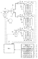
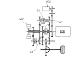
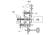
- FIG. 1 is an overall system diagram showing a drive system and a control system of a hybrid vehicle to which a power generation control device of Example 1 is applied.
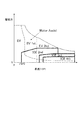
- FIG. 3 is a control system configuration diagram illustrating a configuration of a shift control system of a multi-stage gear transmission mounted on a hybrid vehicle to which the power generation control device of Embodiment 1 is applied. It is a shift map schematic diagram showing the concept of switching the shift speed in a multi-stage gear transmission mounted on a hybrid vehicle to which the power generation control device of Embodiment 1 is applied.
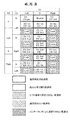
- 3 is a fastening table showing shift stages according to switching positions of three engagement clutches in a multi-stage gear transmission mounted on a hybrid vehicle to which the power generation control device of Embodiment 1 is applied.
- FIG. 3 is a control system configuration diagram illustrating a configuration of a shift control system of a multi-stage gear transmission mounted on a hybrid vehicle to which the power generation control device of Embodiment 1 is applied. It is a shift map schematic diagram showing the concept of
- FIG. 6 is a first shift schedule map diagram showing a shift speed switching region selected when the battery SOC travels in a region from a power generation end threshold value to an upper limit SOCmax. It is a 2nd shift schedule map figure which shows the switching area
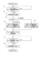
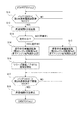
- 3 is a flowchart illustrating a flow of power generation control processing executed by the hybrid control module according to the first embodiment.
- FIG. 6 is a torque flow diagram showing a transmission path of ICE torque and MG1 torque in a multi-stage gear transmission when a gear stage “EV1st ICE-” is selected in series power generation.
- FIG. 6 is a torque flow diagram showing an ICE torque transmission path in a multi-stage gear transmission when a shift stage “EV1st ICE-” is selected in idle power generation.
- 6 is a flowchart illustrating a flow of power generation control processing executed by the hybrid control module according to the second embodiment. It is a figure which shows the case where the electric power generation start threshold value of Example 2 is arrange
- the power generation control device of the first embodiment includes a hybrid vehicle (an example of a hybrid vehicle) including, as drive system components, one engine, two motor generators, and a multi-stage gear transmission having three engagement clutches. Is applied.
- a hybrid vehicle an example of a hybrid vehicle
- the configuration of the power generation control device for the hybrid vehicle in the first embodiment will be described by being divided into “overall system configuration”, “shift control system configuration”, “shift speed configuration”, and “power generation control processing configuration”.
- FIG. 1 shows a drive system and a control system of a hybrid vehicle to which the power generation control device of the first embodiment is applied.
- the overall system configuration will be described below with reference to FIG.
- the drive system of the hybrid vehicle includes an internal combustion engine ICE, a first motor generator MG1, a second motor generator MG2, and a multi-stage gear transmission 1 having three engagement clutches C1, C2, C3. (Power split mechanism).
- ICE is an abbreviation for “Internal-Combustion Engine”.
- the internal combustion engine ICE is, for example, a gasoline engine or a diesel engine disposed in the front room of the vehicle with the crankshaft direction as the vehicle width direction.
- the internal combustion engine ICE is connected to the transmission case 10 of the multi-stage gear transmission 1 and the output shaft of the internal combustion engine is connected to the first shaft 11 of the multi-stage gear transmission 1.
- the internal combustion engine ICE basically starts MG2 using the second motor generator MG2 as a starter motor. However, the starter motor 2 is left in preparation for the case where the MG2 start using the high-power battery 3 cannot be secured, such as at a very low temperature.
- Both the first motor generator MG1 and the second motor generator MG2 are three-phase AC permanent magnet synchronous motors using the high-power battery 3 as a common power source.
- the stator of first motor generator MG1 is fixed to the case of first motor generator MG1, and the case is fixed to transmission case 10 of multi-stage gear transmission 1.
- a first motor shaft that is integral with the rotor of first motor generator MG1 is connected to second shaft 12 of multi-stage gear transmission 1.
- the stator of the second motor generator MG2 is fixed to the case of the second motor generator MG2, and the case is fixed to the transmission case 10 of the multi-stage gear transmission 1.
- a second motor shaft integrated with the rotor of second motor generator MG2 is connected to sixth shaft 16 of multi-stage gear transmission 1.
- a first inverter 4 that converts direct current to three-phase alternating current during power running and converts three-phase alternating current to direct current during regeneration is connected to the stator coil of first motor generator MG1 via first AC harness 5.
- a second inverter 6 is connected to the stator coil of the second motor generator MG2 via a second AC harness 7 for converting direct current into three-phase alternating current during power running and converting three-phase alternating current into direct current during regeneration.
- the high-power battery 3 is connected to the first inverter 4 and the second inverter 6 by a DC harness 8 via a junction box 9.
- the multi-stage gear transmission 1 is a constantly meshing transmission having a plurality of gear pairs with different gear ratios, and is arranged in parallel with each other in a transmission case 10 and has six gear shafts 11 to 16 provided with gears. And three engagement clutches C1, C2, C3 for selecting a gear pair.
- As the gear shaft a first shaft 11, a second shaft 12, a third shaft 13, a fourth shaft 14, a fifth shaft 15, and a sixth shaft 16 are provided.
- As the engagement clutch a first engagement clutch C1, a second engagement clutch C2, and a third engagement clutch C3 are provided.
- the transmission case 10 is provided with an electric oil pump 20 that supplies lubricating oil to a bearing portion and a gear meshing portion in the case.
- the first shaft 11 is a shaft to which the internal combustion engine ICE is connected.
- a first gear 101, a second gear 102, and a third gear 103 are arranged in order from the right side of FIG. .
- the first gear 101 is provided integrally (including integrated fixing) with respect to the first shaft 11.
- the second gear 102 and the third gear 103 are idle gears in which bosses protruding in the axial direction are inserted into the outer periphery of the first shaft 11, and are connected to the first shaft 11 via the second engagement clutch C2. It is provided so that drive connection is possible.
- the second shaft 12 is a cylindrical shaft that is connected to the first motor generator MG1 and is coaxially arranged with the axial center aligned with the outer position of the first shaft 11, and the second shaft 12 has a right side in FIG.
- a fourth gear 104 and a fifth gear 105 are arranged in this order.
- the fourth gear 104 and the fifth gear 105 are provided integrally with the second shaft 12 (including integrated fixing).
- the third shaft 13 is a shaft disposed on the output side of the multi-stage gear transmission 1.
- the third shaft 13 includes a sixth gear 106, a seventh gear 107, and an eighth gear in order from the right side of FIG. 108, a ninth gear 109, and a tenth gear 110 are arranged.
- the sixth gear 106, the seventh gear 107, and the eighth gear 108 are provided integrally with the third shaft 13 (including integrated fixing).
- the ninth gear 109 and the tenth gear 110 are idle gears in which bosses protruding in the axial direction are inserted into the outer periphery of the third shaft 13, and are connected to the third shaft 13 via the third engagement clutch C3. It is provided so that drive connection is possible.
- the sixth gear 106 meshes with the second gear 102 of the first shaft 11, the seventh gear 107 meshes with the sixteenth gear 116 of the differential gear 17, and the eighth gear 108 meshes with the third gear 103 of the first shaft 11.
- the ninth gear 109 meshes with the fourth gear 104 of the second shaft 12, and the tenth gear 110 meshes with the fifth gear 105 of the second shaft 12.
- the fourth shaft 14 is a shaft whose both ends are supported by the transmission case 10, and the eleventh gear 111, the twelfth gear 112, and the thirteenth gear 113 are sequentially arranged on the fourth shaft 14 from the right side in FIG. Be placed.
- the eleventh gear 111 is provided integrally with the fourth shaft 14 (including integrated fixation).
- the twelfth gear 112 and the thirteenth gear 113 are idle gears in which bosses protruding in the axial direction are inserted into the outer periphery of the fourth shaft 14, and are connected to the fourth shaft 14 via the first engagement clutch C1. It is provided so that drive connection is possible.
- the eleventh gear 111 is engaged with the first gear 101 of the first shaft 11
- the twelfth gear 112 is engaged with the second gear 102 of the first shaft 11
- the thirteenth gear 113 is engaged with the fourth gear 104 of the second shaft 12. Mesh with.
- the fifth shaft 15 is a shaft whose both ends are supported by the transmission case 10, and a fourteenth gear 114 that meshes with the eleventh gear 111 of the fourth shaft 14 is provided integrally (including integral fixing).
- the sixth shaft 16 is a shaft to which the second motor generator MG2 is connected, and a fifteenth gear 115 that meshes with the fourteenth gear 114 of the fifth shaft 15 is provided integrally (including integrated fixing).
- the second motor generator MG2 and the internal combustion engine ICE are mechanically connected by a gear train including a 15th gear 115, a 14th gear 114, an 11th gear 111, and a first gear 101 that mesh with each other.
- This gear train is a reduction gear train that decelerates the MG2 rotation speed when the internal combustion engine ICE is started by the second motor generator MG2, and the engine rotation is generated during the MG2 power generation that generates the second motor generator MG2 by driving the internal combustion engine ICE. It becomes a speed increasing gear train that increases the number.
- the first engagement clutch C1 is interposed between the twelfth gear 112 and the thirteenth gear 113 of the fourth shaft 14, and is not fastened by a meshing stroke in a rotationally synchronized state by having no synchronization mechanism. It is a dog clutch.
- the first engagement clutch C1 When the first engagement clutch C1 is in the left engagement position (Left), the fourth shaft 14 and the thirteenth gear 113 are drivingly connected.
- the first engagement clutch C1 is in the neutral position (N), the fourth shaft 14 and the twelfth gear 112 are released, and the fourth shaft 14 and the thirteenth gear 113 are released.
- the first engagement clutch C1 is in the right engagement position (Right), the fourth shaft 14 and the twelfth gear 112 are drivingly connected.
- the second engagement clutch C2 is interposed between the second gear 102 and the third gear 103 of the first shaft 11, and is not fastened by a meshing stroke in a rotationally synchronized state by having no synchronization mechanism. It is a dog clutch.
- the second engagement clutch C2 When the second engagement clutch C2 is in the left engagement position (Left), the first shaft 11 and the third gear 103 are drivingly connected.
- the second engagement clutch C2 When the second engagement clutch C2 is in the neutral position (N), the first shaft 11 and the second gear 102 are released, and the first shaft 11 and the third gear 103 are released.
- the second engagement clutch C2 is in the right engagement position (Right), the first shaft 11 and the second gear 102 are drivingly connected.
- the third engagement clutch C3 is interposed between the ninth gear 109 and the tenth gear 110 of the third shaft 13, and is not fastened by a meshing stroke in a rotationally synchronized state by having no synchronization mechanism. It is a dog clutch.
- the third engagement clutch C3 When the third engagement clutch C3 is in the left side engagement position (Left), the third shaft 13 and the tenth gear 110 are drivingly connected.
- the third engagement clutch C3 is in the neutral position (N), the third shaft 13 and the ninth gear 109 are released, and the third shaft 13 and the tenth gear 110 are released.
- the third engagement clutch C3 is in the right engagement position (Right), the third shaft 13 and the ninth gear 109 are drivingly connected.
- a sixteenth gear 116 meshed with a seventh gear 107 provided integrally (including integral fixing) with the third shaft 13 of the multi-stage gear transmission 1 is left and right via the differential gear 17 and the left and right drive shafts 18. Are connected to the drive wheel 19.
- the hybrid vehicle control system includes a hybrid control module 21, a motor control unit 22, a transmission control unit 23, and an engine control unit 24.
- the hybrid control module 21 (abbreviation: “HCM”) is an integrated control means having a function of appropriately managing the energy consumption of the entire vehicle.
- the hybrid control module 21 is connected to other control units (such as a motor control unit 22, a transmission control unit 23, and an engine control unit 24) via a CAN communication line 25 so that bidirectional information can be exchanged.
- CAN of the CAN communication line 25 is an abbreviation of “Controller Area Network”.
- the motor control unit 22 (abbreviation: “MCU”) performs power running control and regenerative control of the first motor generator MG1 and the second motor generator MG2 in accordance with control commands for the first inverter 4 and the second inverter 6.
- Control modes for the first motor generator MG1 and the second motor generator MG2 include “torque control” and “rotational speed FB control”. “Torque control” performs control for causing the actual motor torque to follow the target motor torque when the target motor torque to be shared with respect to the target torque is determined.
- “Rotational speed FB control” determines the target motor rotational speed to synchronize the clutch input / output rotational speed when there is a shift request for meshing and engaging any of the engagement clutches C1, C2, and C3 during travel. Control is performed to output FB torque so that the rotation speed converges to the target motor rotation speed.
- the transmission control unit 23 (abbreviation: “TMCU”) outputs a current command to the electric actuators 31, 32, 33 (see FIG. 2) based on predetermined input information, thereby shifting the multi-stage gear transmission 1. Shift control for changing gears is performed.
- the engagement clutches C1, C2, and C3 are selectively meshed and engaged / released, and a gear pair involved in power transmission is selected from a plurality of pairs of gears.
- the first motor generator MG1 or the first motor is used to ensure mesh engagement by suppressing the differential rotational speed of the clutch input / output.
- 2-Rotation speed FB control rotation synchronization control
- the engine control unit 24 (abbreviation: “ECU”) outputs a control command to the motor control unit 22, the ignition plug, the fuel injection actuator, and the like based on predetermined input information, thereby controlling the start-up of the internal combustion engine ICE and the internal combustion engine. Performs engine ICE stop control and fuel cut control.
- the multi-stage gear transmission 1 is characterized in that efficiency is improved by reducing drag by employing engagement clutches C1, C2, and C3 (dog clutches) by mesh engagement as transmission elements. . If there is a shift request for engaging and engaging any of the engagement clutches C1, C2, and C3, the differential rotational speed of the clutch input / output is set to the first motor generator MG1 (when the engagement clutch C3 is engaged) or the second motor. This is realized by synchronizing the rotation with the generator MG2 (when the engagement clutches C1 and C2 are engaged) and starting the meshing stroke when it is within the synchronization determination rotation speed range.
- the transmission control system includes a first engagement clutch C1, a second engagement clutch C2, and a third engagement clutch C3 as engagement clutches.
- a first electric actuator 31 for C2, C3 shift operation, a second electric actuator 32 for C2, C3 selection operation, and a third electric actuator 33 for C3 shift operation are provided.
- a C1 / C2 select operation mechanism 40, a C1 shift operation mechanism 41, a C2 shift operation mechanism 42, and a C3 shift operation mechanism 43 are provided as shift mechanisms that convert the actuator operation into clutch engagement / release operation.
- a transmission control unit 23 is provided as a control means for the first electric actuator 31, the second electric actuator 32, and the third electric actuator 33.
- the first engagement clutch C1, the second engagement clutch C2, and the third engagement clutch C3 are in a neutral position (N: release position), a left engagement position (Left: left clutch engagement engagement position), and a right engagement position. (Right: right clutch meshing engagement position).
- Each of the engagement clutches C1, C2, and C3 has the same configuration, and includes coupling sleeves 51, 52, and 53, left dog clutch rings 54, 55, and 56, and right dog clutch rings 57, 58, and 59.
- the coupling sleeves 51, 52, and 53 are provided so as to be capable of stroke in the axial direction by spline coupling via hubs (not shown) fixed to the fourth shaft 14, the first shaft 11, and the third shaft 13.
- dog teeth 51a, 51b, 52a, 52b, 53a, 53b with flat top surfaces are provided on both sides. Furthermore, fork grooves 51c, 52c, and 53c are provided at the center portions in the circumferential direction of the coupling sleeves 51, 52, and 53.
- the left dog clutch rings 54, 55, 56 are fixed to the bosses of the respective gears 113, 103, 110, which are the left idle gears of the respective engagement clutches C1, C2, C3, and are flat top surfaces facing the dog teeth 51a, 52a, 53a. Dog teeth 54a, 55a, and 56a.
- the right dog clutch rings 57, 58, 59 are fixed to the bosses of the respective gears 112, 102, 109, which are the right idle gears of the engagement clutches C1, C2, C3, and are flat top surfaces facing the dog teeth 51b, 52b, 53b. Dog teeth 57b, 58b, 59b.
- the C1 / C2 select operation mechanism 40 has a first position for selecting connection between the first electric actuator 31 and the C1 shift operation mechanism 41, and a second position for selecting connection between the first electric actuator 31 and the C2 shift operation mechanism 42. And a mechanism for selecting between.
- first position is selected, the shift rod 62 and the shift rod 64 of the first engagement clutch C1 are connected, and the shift rod 65 of the second engagement clutch C2 is locked at the neutral position.
- the second position is selected, the shift rod 62 and the shift rod 65 of the second engagement clutch C2 are connected, and the shift rod 64 of the first engagement clutch C1 is locked at the neutral position. That is, when a position for shifting one engagement clutch is selected from the first position and the second position, the other engagement clutch is locked and fixed at the neutral position.
- the C1 shift operation mechanism 41, the C2 shift operation mechanism 42, and the C3 shift operation mechanism 43 are mechanisms that convert the rotation operation of the electric actuators 31, 33 into the axial stroke operation of the coupling sleeves 51, 52, 53. .
- Each of the shift operation mechanisms 41, 42, 43 has the same configuration, and includes rotation links 61, 63, shift rods 62, 64, 65, 66, and shift forks 67, 68, 69.
- One end of each of the rotation links 61 and 63 is provided on the actuator shaft of the electric actuators 31 and 33, and the other end is connected to the shift rod 64 (or the shift rod 65) and 66 so as to be relatively displaceable.
- the shift rods 64, 65, 66 are provided with springs 64 a, 65 a, 66 a at rod division positions, and can be expanded and contracted according to the magnitude and direction of the rod transmission force.
- One end of the shift forks 67, 68, 69 is fixed to the shift rods 64, 65, 66, and the other end is disposed in the fork grooves 51c, 52c, 53c of the coupling sleeves 51, 52, 53.
- the transmission control unit 23 includes a vehicle speed sensor 71, an accelerator opening sensor 72, a transmission output shaft rotational speed sensor 73, an engine rotational speed sensor 74, an MG1 rotational speed sensor 75, an MG2 rotational speed sensor 76, an inhibitor switch 77, a battery.
- a sensor signal or a switch signal from the SOC sensor 78 or the like is input.
- the transmission output shaft rotation speed sensor 73 is provided at the shaft end of the third shaft 13 and detects the shaft rotation speed of the third shaft 13.
- a position servo control unit (for example, a position servo system based on PID control) that controls engagement and disengagement of engagement clutches C1, C2, and C3 determined by the positions of the coupling sleeves 51, 52, and 53 is provided.
- This position servo control unit inputs sensor signals from the first sleeve position sensor 81, the second sleeve position sensor 82, and the third sleeve position sensor 83. Then, the sensor values of the sleeve position sensors 81, 82, 83 are read, and electric currents are supplied to the electric actuators 31, 32, 33 so that the positions of the coupling sleeves 51, 52, 53 become the fastening position or the releasing position by the meshing stroke. give. In other words, the idle gear is set in the engagement state where the dog teeth welded to the coupling sleeves 51, 52, 53 and the dog teeth welded to the idle gear are engaged with each other, so that the idle gear is in the fourth axis.
- the multi-stage gear transmission 1 of the first embodiment reduces power transmission loss by not having a rotation difference absorbing element such as a fluid coupling, and reduces the ICE gear stage by assisting the internal combustion engine ICE by motors, thereby reducing the size ( EV shift stage: 1-2 speed, ICE shift stage: 1-4 speed).
- a rotation difference absorbing element such as a fluid coupling
- the gear configuration of the multi-stage gear transmission 1 will be described with reference to FIGS. 3 and 4.
- the concept of the gear position is that, in the starting region where the vehicle speed VSP is equal to or lower than the predetermined vehicle speed VSP0, the multi-stage gear transmission 1 does not have a starting element (sliding element). Motor start (EV start) using only power.
- the traveling region as shown in FIG. 3, when the demand for the driving force is large, the concept of the shift stage is adopted in which the engine driving force is supported by the “parallel HEV mode” that assists with the motor driving force. That is, as the vehicle speed VSP increases, the ICE shift speed shifts from (ICE1st ⁇ ) ICE2nd ⁇ ICE3rd ⁇ ICE4th, and the EV shift speed shifts from EV1st ⁇ EV2nd. Therefore, a shift map for issuing a shift request for switching the shift stage is created based on the concept of the shift stage shown in FIG.
- FIG. 4 shows all the speeds that can be theoretically realized by the multi-stage gear transmission 1 having the engagement clutches C1, C2, and C3.
- “Lock” in FIG. 4 represents an interlock shift stage that is not established as a shift stage
- “EV-” represents a state in which the first motor generator MG1 is not drivingly connected to the drive wheels 19
- “ICE” “-” Represents a state in which the internal combustion engine ICE is not drivingly connected to the drive wheels 19.
- each gear stage will be described.
- the shift stage of “EV-ICEgen” is selected at the time of MG1 idle power generation by the first motor generator MG1 by the internal combustion engine ICE or double idle power generation by adding MG2 power generation to MG1 power generation while the vehicle is stopped. It is a shift stage.
- the “Neutral” gear stage is a gear stage that is selected during MG2 idle power generation by the second motor generator MG2 by the internal combustion engine ICE while the vehicle is stopped.
- the shift stage of “EV2nd ICE-” is set in the “EV mode” in which the internal combustion engine ICE is stopped and the first motor generator MG1 travels, or while the second motor generator MG2 generates power with the internal combustion engine ICE. This is the gear stage selected in the “series HEV mode” in which the first motor generator MG1 performs the second-speed EV traveling.
- the multi-stage gear transmission 1 uses the multi-stage gear transmission 1 to remove all the gear stages from the "interlock gear stage (cross-hatching in FIG. 4)" and "the gear stage that cannot be selected by the shift mechanism (upward hatching in FIG. 4)". A plurality of shift stages that can be realized.
- the gears that cannot be selected by the shift mechanism include “EV1.5 ICE2nd” in which the first engagement clutch C1 is “Left” and the second engagement clutch C2 is “Left”, and the first engagement “EV2.5 ICE4th” in which the clutch C1 is “Left” and the second engagement clutch C2 is “Right”.
- the reason why it cannot be selected by the shift mechanism is that one first electric actuator 31 is a shift actuator that is also used for the two engagement clutches C1 and C2, and one engagement clutch by the C1 / C2 selection operation mechanism 40. Is due to being neutral locked.
- the “normally used shift speeds” include EV shift speed (EV1st1ICE-, EV2nd ICE-), ICE shift speed (EV- ICE2nd, EV- ICE3rd, EV- ICE4th), and combination shift speed (EV1st ICE2nd, EV1st ICE3rd, EV2nd ICE2nd, EV2nd ICE3rd, EV2nd ICE4th) is added by adding “Neutral”.
- three schedule maps, a first schedule map map1 to a third schedule map map3, are set as an example for issuing a shift request for switching the shift speed.
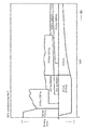
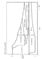
- FIG. 9 is an energy management map showing the battery SOC and the engine speed according to the first embodiment, which will be described later.
- areas for using the first schedule map map1 to the third schedule map map3 are set according to the battery SOC. That is, the first schedule map map1 is used when the battery SOC is a middle to high SOC region (a region indicated by map1 in the figure) from the predetermined value SOC2 (power generation end threshold, first common power generation end threshold) to the upper limit SOCmax. .
- the second schedule map map2 Is used.
- the third schedule map ma3 is used in the middle SOC region (the region indicated as map3 in the figure) where the battery SOC is from the predetermined value SOC1 to the predetermined value SOC2.
- the “first shift schedule map map1” uses a vehicle speed VSP and a required braking / driving force (Driving force) as coordinate axes, and selects a plurality of shift speeds constituting a normal use shift speed group on the coordinate plane. This is a map to which a selection area to be assigned is assigned. In other words, in the “first shift schedule map map1”, a selection region of “EV1st” is assigned to the low vehicle speed range from the start as the drive drive region by depressing the accelerator.
- the EV2nd, EV1st ICE2nd, EV1st ICE3rd, EV2nd ICE2nd, EV2nd ICE3rd, and EV2nd ICE4th selection areas are assigned to the medium to high vehicle speed range.
- a selection area of “EV1st” is assigned to the low vehicle speed range
- a selection area of “EV2nd” is assigned to the middle to high vehicle speed range.
- the “second shift schedule map map2” selects a plurality of shift speeds that constitute a normal-use shift speed group on the coordinate plane with the vehicle speed VSP and the required braking / driving force as the coordinate axes. This is a map to which a selection area to be assigned is assigned. Also, the “second shift schedule map map2” adds “Series EV1st” and “EV1st ICE1st” to the drive area of the coordinate plane, while omitting “EV2nd”, compared to the “first shift schedule map map1”. The map is designed to reduce power consumption.
- the selection range of “Series EV1st” is allocated to the start-low vehicle speed range as the drive drive range by depressing the accelerator, and the parallel HEV mode is selected in this “Series EV1st” selection range. Mode transition is not possible.
- the EV1st ICE1st, EV1st ICE2nd, and EV1st ICE3rd selection areas are assigned to the medium vehicle speed range, and the EV2nd ICE2nd, EV2nd ICE3rd, and EV2nd ICE4th selection areas are assigned to the high vehicle speed range. It is done.
- a selection area of “EV1st (EV2nd)” is assigned to the low vehicle speed range
- a selection area of “EV2nd” is assigned to the middle to high vehicle speed range.
- the “third shift schedule map map3” indicates the selection areas of “EV1st” and “EV2nd” in the EV mode in the drive driving area of the “first shift schedule map map1”, respectively. Allocated to EV1st and Series EV2nd. In other words, in the selected range of “Series EV1st” and “Series EV2nd”, EV driving is performed by the first motor generator MG1 while generating power by the second motor generator MG2 by the internal combustion engine ICE, and the increase in the battery SOC is further suppressed. It is also possible to plan. Further, in the “third shift schedule map map3”, the mode cannot be changed to the parallel HEV mode in the selected region of “Series EV1st”.
- FIG. 8 shows a flow of power generation control processing executed by the hybrid control module 21 of the first embodiment (power generation controller).
- FIG. 9 shows a case where the power generation start threshold value of the first embodiment is aligned with the first common power generation start threshold value, and is an energy management map showing the battery SOC and engine speed of the first embodiment.
- FIG. 9 shows the power generation start threshold, the power generation end threshold, and the engine speed at each power generation on the coordinate plane with the battery SOC and the engine speed Ne (Engine Speed) as coordinate axes.
- Ne Engine Speed
- step S1 it is determined whether or not the battery SOC (battery charge capacity) is lower than the first common power generation start threshold SOC1. If YES (battery SOC ⁇ first common power generation start threshold SOC1), the process proceeds to step S2. If NO (battery SOC ⁇ first common power generation start threshold SOC1), step S1 is repeated.
- battery SOC is the battery charge capacity of the high-power battery 3, and battery SOC information is acquired by the SOC sensor 78.
- the “power generation start threshold” includes a series power generation start threshold (predetermined value SOC1) of the battery SOC for starting series power generation and an idle power generation start threshold (predetermined value of the battery SOC for starting idle power generation). Value SOC3).
- This “series power generation start threshold SOC1” is set to a value that does not use a battery SOC region that is so low as to adversely affect the life of the high-power battery 3 and that keeps the battery SOC within a range that does not require limiting the motor output during driving. Is done.
- “Series power generation start threshold SOC1” set in this way is an optimum value as a threshold for starting series power generation from the viewpoint of battery SOC management.
- the “idle power generation start threshold SOC3” is a value in which the battery SOC is maintained in a range where the charging frequency of the high-power battery 3 is less than that of the series power generation, and the motor output at the time of traveling is not required to be limited. Is set.
- the idle power generation start threshold value SOC3 (two-dot chain line in FIG. 9) is aligned with the series power generation start threshold value SOC1 on the higher side of the two threshold values as indicated by an arrow A in FIG. For this reason, when the idle power generation start threshold value SOC3 is aligned with the series power generation start threshold value SOC1, the number of times of idle power generation increases compared to when the idle power generation start threshold value SOC3 is not aligned with the series power generation start threshold value SOC1.
- the power generation start threshold value in the case of the arrangement is defined as “first common power generation start threshold value SOC1”.
- step S2 following the determination of “battery SOC ⁇ first common power generation start threshold SOC1” in step S1, the internal combustion engine ICE is started, and the process proceeds to step S3.
- step S3 it is determined whether or not the vehicle is running following “starting of the internal combustion engine ICE” in step S2. If YES (running), the process proceeds to step S4. If NO (stopped), the process proceeds to step S5.
- whether or not the vehicle is “running” is determined from a plurality of pieces of information such as vehicle speed VSP information from the vehicle speed sensor 71.
- step S4 following the determination of “traveling” in step S3, the engine speed (internal combustion engine speed, ICE speed) Ne is increased to the power generation speed during travel, and the process proceeds to step S6. That is, in order to output engine torque (internal combustion engine torque, ICE torque) corresponding to power generation torque during traveling, the engine speed Ne is increased to the first engine speed Ne1.
- the engine speed Ne0 is zero.
- step S5 following the determination of “stopped” in step S3, the engine speed Ne is increased to the power generation speed being stopped, and the process proceeds to step S6. That is, the engine speed Ne is increased to the third engine speed Ne3 in order to output the engine torque corresponding to the generated power generation torque while the vehicle is stopped.
- the third engine speed Ne3 during idle power generation when the idle power generation start threshold SOC3 is aligned with the series power generation start threshold SOC1, and the idle power generation start threshold SOC3 is set as the series power generation start threshold as shown by the arrow B in FIG. It is set lower than the second engine speed Ne2 (two-dot chain line in FIG. 9) at the time of idle power generation when not aligned with SOC1 (second engine speed Ne2> third engine speed Ne3).
- step S6 following the increase to the first engine speed Ne1 in step S4 or the third engine speed Ne3 in step S5, the second motor generator receives the driving force from the internal combustion engine ICE.
- Power generation starts with MG2. That is, series power generation (“Series EV1st”) is started when the vehicle is traveling, and idle power generation (MG2 idle power generation, “EV1st”) is started when the vehicle is stopped.
- Series EV1st series power generation
- EV1st idle power generation
- step S7 following the start of power generation in step S6, it is determined whether or not the battery SOC is higher than the first common power generation end threshold SOC2. If YES (battery SOC> first common power generation end threshold SOC2), the process proceeds to step S8, and if NO (battery SOC ⁇ first common power generation end threshold SOC2), step S7 is repeated.
- the “power generation end threshold” includes a series power generation end threshold (predetermined value SOC2) of the battery SOC that ends the series power generation and an idle power generation end threshold of the battery SOC that ends the idle power generation. .
- the idle power generation end threshold value is aligned with the series power generation end threshold value SOC2.
- the power generation end threshold value in the case of the arrangement is defined as “first common power generation end threshold SOC2”.
- the idle power generation end threshold when not matching the series power generation end threshold SOC2 is, for example, a value greater than the idle power generation start threshold SOC3 and smaller than the series power generation start threshold SOC1.
- step S8 following the determination of “battery SOC> first common power generation end threshold SOC2” in step S7, the internal combustion engine ICE is stopped and the process proceeds to the end. At the end, since the power generation is completed, it becomes “EV1st”.
- step S1 is repeated in the flowchart of FIG. 8 until it is determined in step S1 that the battery SOC is lower than the first common power generation start threshold value SOC1.
- step S1 if it is determined in step S1 that the battery SOC is lower than the first common power generation start threshold SOC1, the flow from step S1 to step S2 is the same.
- step S3 it is determined whether the vehicle is traveling. If it is determined in step S3 that the vehicle is traveling, the process proceeds from step S3 to step S4 ⁇ step S6 ⁇ step S7.
- step S4 the engine speed is increased to the first engine speed Ne1, which is the power generation speed during traveling, and in step S6, series power generation ("Series EV1st") is started (executed).
- step S7 it is determined whether or not the battery SOC is higher than the series power generation end threshold SOC2.
- step S7 it is determined in step S7 that “battery SOC ⁇ first common power generation end threshold SOC2”. For this reason, step S7 is repeated until it is determined in step S7 that “battery SOC> first common power generation end threshold SOC2”.
- step S7 When it is determined in step S7 that “battery SOC> first common power generation end threshold SOC2”, the process proceeds from step S7 to step S8 ⁇ END.
- step S8 the internal combustion engine ICE is stopped. That is, the power generation control of series power generation is a flow that proceeds from START ⁇ step S1 ⁇ step S2 ⁇ step S3 ⁇ step S4 ⁇ step S6 ⁇ step S7 ⁇ step S8 ⁇ end in the flowchart of FIG.
- the first engagement clutch C1 is in the “N” position
- the second engagement clutch C2 is in the “N” position
- the third engagement clutch C3 Is the “Left” position.
- the MG1 torque is derived from the first motor generator MG1 from the second shaft 12 ⁇ the fifth gear 105 ⁇ the tenth gear 110 ⁇ the third shaft 13 ⁇ the seventh gear 107 ⁇ the sixteenth gear 116 ⁇ the differential gear 17 ⁇ the drive shaft 18 ⁇ It flows to the drive wheel 19.
- the ICE torque flows from the internal combustion engine ICE to the first shaft 11 ⁇ the first gear 101 ⁇ the eleventh gear 111 ⁇ the fourteenth gear 114 ⁇ the fifteenth gear 115 ⁇ the sixth shaft 16 ⁇ the second motor generator MG2.
- Electric power is generated by the two-motor generator MG2.
- the second motor generator MG2 generates power by receiving the driving force from the internal combustion engine ICE.
- step S1 to step S3 is the same as the “power generation control processing operation in series power generation”, and thus the description thereof is omitted.
- step S3 it is determined whether or not the vehicle is traveling. If it is determined in step S3 that the vehicle is stopped, the process proceeds from step S3 to step S5 ⁇ step S6 ⁇ step S7. In step S5, the engine speed is increased to the third engine speed Ne3 that is the stopped power generation speed, and in step S6, idle power generation ("EV1st") is started (executed). Next, in step S7, it is determined whether or not the battery SOC is higher than the first common power generation end threshold SOC2.
- step S7 the high-power battery 3 is charged by the second motor generator MG2 in response to the driving force from the internal combustion engine ICE.
- step S7 it is determined in step S7 that “battery SOC ⁇ first common power generation end threshold SOC2”, and step S7 is repeated.
- the engine speed Ne is the third engine speed Ne3, which is lower than the second engine speed Ne2, so that power is generated at the third engine speed Ne3 than when power is generated at the second engine speed Ne2.
- the engine sound (the sound of the internal combustion engine ICE) is smaller when the operation is performed.
- step S7 When it is determined in step S7 that “battery SOC> first common power generation end threshold SOC2”, the process proceeds from step S7 to step S8 ⁇ END.
- step S8 the internal combustion engine ICE is stopped. That is, the power generation control of idle power generation is a flow that proceeds from START ⁇ step S1 ⁇ step S2 ⁇ step S3 ⁇ step S5 ⁇ step S6 ⁇ step S7 ⁇ step S8 ⁇ end in the flowchart of FIG.
- the first engagement clutch C1 is in the “N” position
- the second engagement clutch C2 is in the “N” position
- the third engagement clutch C3 is in the “Left” position. is there. Accordingly, the ICE torque flows from the internal combustion engine ICE to the first shaft 11 ⁇ the first gear 101 ⁇ the eleventh gear 111 ⁇ the fourteenth gear 114 ⁇ the fifteenth gear 115 ⁇ the sixth shaft 16 ⁇ the second motor generator MG2.
- Electric power is generated by the two-motor generator MG2.
- the second motor generator MG2 generates power by receiving the driving force from the internal combustion engine ICE while the vehicle is stopped.
- a power generation control device for a hybrid vehicle that conventionally performs series power generation during traveling and idle power generation during stopping is used as a comparative example.
- the battery SOC threshold value which is a threshold value for starting charging
- the hybrid vehicle has two threshold values: a battery SOC threshold value for starting the engine while the vehicle is stopped and a battery SOC threshold value for traveling. . This aims to reduce dissatisfaction with passenger noise.
- the power generation control device for the hybrid vehicle of the comparative example has a configuration having two battery SOC threshold values during stopping and two battery SOC threshold values during traveling. For this reason, there is a problem that when the vehicle is stopped and started repeatedly, control hunting is performed in which the engine starts and stops repeatedly, the engine sound changes greatly, and the passenger feels uncomfortable.
- the series power generation start threshold SOC1 of the battery charge capacity for starting the series power generation and the idle power generation start threshold SOC3 of the battery charge capacity for starting the idle power generation have the same value (first common power generation).
- the start threshold value SOC1) is set (step S1 in FIG. 8 and FIG. 9). That is, by setting the series power generation start threshold value SOC1 and the idle power generation start threshold value SOC3 to the same value (first common power generation start threshold value SOC1), for example, in a traveling scene in which the vehicle stops and starts repeatedly, such as in a traffic jam, The ICE will not start and stop repeatedly. Therefore, the uncomfortable feeling given to the occupant is prevented in the traveling scene where the vehicle stops and starts repeatedly.
- the idle power generation start threshold value SOC3 is aligned with the series power generation start threshold value SOC1 on the higher side of the two threshold values (step S1 in FIG. 8). And FIG. 9).
- the third engine speed Ne3 at the time of idle power generation when aligning the idle power generation start threshold SOC3 with the series power generation start threshold SOC1 is the same as the third engine speed Ne3 at the time of idle power generation when the idle power generation start threshold SOC3 is not aligned with the series power generation start threshold SOC1. 2
- the engine speed Ne2 is set lower (step S5 in FIG. 8 and FIG. 9).
- the idle power generation start threshold SOC3 is aligned with the series power generation start threshold SOC1 (first common power generation start threshold SOC1) on the higher side of the two thresholds.
- the engine speed Ne during idle power generation is set to a third engine speed Ne3 that is lower than the second engine speed Ne2.
- the number of idle power generation (power generation frequency) while the vehicle is stopped increases. Will be increased.
- the number of start-ups of the internal combustion engine ICE increases, but the third engine speed Ne3, which is the engine speed Ne at the time of idle power generation, is set lower than the second engine speed Ne2. For this reason, the sound of the internal combustion engine ICE at the third engine speed Ne3 is smaller than the sound of the internal combustion engine ICE at the second engine speed Ne2. Therefore, when the idle power generation start threshold value SOC3 is aligned with the higher series power generation start threshold value SOC1 of the two threshold values, the passenger is less likely to feel dissatisfied with the noise of the internal combustion engine ICE during idle power generation. In addition, since the number of idle power generations when the vehicle is stopped increases, it is possible to secure the generated power during idle power generation rather than aligning the series power generation start threshold SOC1 with the idle power generation start threshold SOC3.
- the series power generation is performed in the series HEV mode when the vehicle travels at a low vehicle speed range (FIGS. 3 and 6 to 9).
- the engine speed is a unique value determined by the vehicle speed and the gear ratio. For this reason, when the vehicle is traveling in a low vehicle speed range, the engine speed is low and a sufficient power generation amount cannot be ensured.
- the engine is operated at a low speed, the natural frequency of the drive system and the engine speed coincide with each other, and there is a possibility that low-frequency noise called a booming noise is generated.
- series power generation in the series HEV mode is performed in the low vehicle speed range traveling scene.
- the operating point (rotation speed, torque) of the internal combustion engine ICE can be freely determined regardless of the vehicle speed. Accordingly, when the vehicle is traveling in a low vehicle speed range, a sufficient power generation amount is ensured and the generation of a booming noise is prevented. In addition, when the vehicle travels in a vehicle speed range larger than the low vehicle speed range, the vehicle can travel and generate power in a parallel HEV mode with less energy conversion and better fuel efficiency.
- the series power generation is performed in the series HEV mode when the driving scene is limited in the low vehicle speed range where the mode cannot be changed to the parallel HEV mode (FIGS. 3 and 6 to 9). Therefore, power is generated in the series HEV mode even in a driving scene in a low vehicle speed range where the mode cannot be changed to the parallel HEV mode.
- first electric motor first motor generator MG1
- second electric motor second motor generator MG2
- a battery high power battery 3 electrically coupled to the first electric motor (first motor generator MG1) and the second electric motor (second motor generator MG2)
- first electric motor first motor generator MG1
- second motor generator MG2 second electric motor generator MG2
- a power generation controller (hybrid control module 21) that performs idle power generation by at least one of the first electric motor (first motor generator MG1) and the second electric motor (second motor generator MG2) in response to the driving force from the ICE.
- the power generation controller includes a series power generation start threshold SOC1 of a charge capacity (battery SOC, SOC) of a battery (high power battery 3) that starts series power generation, and a battery (high power battery 3) that starts idle power generation.
- the idle power generation start threshold value SOC3 of the charge capacity (battery SOC, SOC) is set to the same value (first common power generation start threshold value SOC1) (FIGS. 8 and 9). For this reason, it is possible to prevent a sense of discomfort given to the occupant in a traveling scene in which the vehicle stops and starts repeatedly.
- the power generation controller SOC1 sets the idle power generation start threshold SOC3 as the higher one of the two thresholds.
- the internal combustion engine speed (third engine speed Ne3) during idle power generation when the idle power generation start threshold SOC3 is aligned with the series power generation start threshold SOC1, and the idle power generation start threshold SOC3 is set to the series power generation start threshold SOC1. It is set lower than the internal combustion engine speed (second engine speed Ne2) at the time of idle power generation when not aligned (FIGS. 8 and 9).
- the power split mechanism (multi-stage gear transmission 1) does not have a starting element that absorbs the rotational difference, and has a system configuration that starts EV using the first electric motor (first motor generator MG1) as a driving source when starting.
- the power generation controller (hybrid control module 21) performs series power generation in the series HEV mode when the driving scene is limited in the low vehicle speed range where the mode cannot be changed to the parallel HEV mode (FIGS. 3, 6 to 9). For this reason, in addition to the effect of (3), power can be generated in the series HEV mode even in a driving scene in which the mode is not limited to the parallel HEV mode and the low vehicle speed range is limited.
- the second embodiment is a modification in which the series power generation start threshold SOC1 is aligned with the idle power generation start threshold SOC3. Based on FIG.12 and FIG.13, the principal part structure of Example 2 is demonstrated below.
- FIG. 13 is an energy management map showing the battery SOC and the engine speed in the second embodiment, which will be described later. As shown in this energy management map diagram, areas for using the first schedule map map1 to the third schedule map map3 are set according to the battery SOC.
- the first schedule map map1 is used when the battery SOC is a middle to high SOC region (a region indicated by map1 in the figure) from the predetermined value SOC4 (power generation end threshold, second common power generation end threshold) to the upper limit SOCmax.
- the second schedule map map2 is used in the low SOC region (the region indicated as map2 in the figure) from the predetermined value SOC0 where the battery SOC is zero to the predetermined value SOC3 (power generation start threshold, second common power generation start threshold).
- the third schedule map ma3 is used in the low to medium SOC region (region indicated as map3 in the drawing) where the battery SOC is from the predetermined value SOC3 to the predetermined value SOC4. Note that specific configuration examples of the first schedule map map1 to the third schedule map map3 described above are the same as the description based on FIGS.
- FIG. 12 shows a flow of power generation control processing executed by the hybrid control module 21 of the second embodiment (power generation controller).
- FIG. 13 is an energy management map diagram showing a case where the power generation start threshold value of the second embodiment is aligned with the second common power generation start threshold value and showing the battery SOC and the engine speed of the second embodiment.
- FIG. 13 shows the power generation start threshold, the power generation end threshold, and the engine speed at each power generation on the coordinate plane with the battery SOC and the engine speed Ne (Engine Speed) as coordinate axes.
- Ne Engine Speed
- step S11 it is determined whether or not the battery SOC is lower than the second common power generation start threshold SOC3. If YES (battery SOC ⁇ second common power generation start threshold SOC3), the process proceeds to step S12. If NO (battery SOC ⁇ second common power generation start threshold SOC3), step S11 is repeated.
- the “power generation start threshold” includes an idle power generation start threshold (predetermined value SOC3) of the battery SOC that starts idle power generation, and a series power generation start threshold ( There is a predetermined value SOC1).
- the series power generation start threshold value SOC1 two-dot chain line in FIG.
- the power generation start threshold value in the case of the arrangement is set to “second common power generation start threshold value SOC3”. Further, the settings of “battery SOC” and “series power generation start threshold SOC1” and “idle power generation start threshold SOC3” are the same as those described in step S1, and thus description thereof is omitted.
- step S14 following the determination of “traveling” in step S13, the engine speed Ne is increased to the power generation speed during traveling, and the process proceeds to step S16. That is, in order to output the engine torque corresponding to the power generation torque during traveling, the engine speed Ne is increased to the fourth engine speed Ne4.
- the fourth engine speed Ne4 at the time of series power generation when the series power generation start threshold value SOC1 is aligned with the idle power generation start threshold value SOC3 is set to the series power generation start threshold value SOC1. It is set higher than the first engine speed Ne1 (two-dot chain line in FIG. 13) at the time of series power generation when not aligned with SOC3 (first engine speed Ne1 ⁇ fourth engine speed Ne4).
- step S15 following the determination of “stopped” in step S13, the engine speed Ne is increased to the power generation speed being stopped, and the process proceeds to step S16. That is, the engine speed Ne is increased to the second engine speed Ne2 in order to output the engine torque corresponding to the generated power generation torque while the vehicle is stopped.
- step S17 following the start of power generation in step S16, it is determined whether or not the battery SOC is higher than the second common power generation end threshold SOC4. If YES (battery SOC> second common power generation end threshold SOC4), the process proceeds to step S18. If NO (battery SOC ⁇ second common power generation end threshold SOC4), step S17 is repeated.
- the “power generation end threshold” includes the idle power generation end threshold (predetermined value SOC4) of the battery SOC that ends idle power generation and the series power generation end threshold of the battery SOC that ends series power generation. is there.
- the series power generation end threshold is aligned with the idle power generation end threshold SOC4.
- the power generation end threshold value in the case of the arrangement is defined as “second common power generation end threshold SOC4”.
- the series power generation end threshold when the idle power generation end threshold SOC4 is not aligned is, for example, a value greater than the series power generation start threshold SOC1.
- battery SOC is the same as that in step S7, and thus the description thereof is omitted.
- step S11 is repeated in the flowchart of FIG. 12 until it is determined in step S11 that the battery SOC is lower than the second common power generation start threshold SOC3.
- step S11 if it is determined in step S11 that the battery SOC is lower than the second common power generation start threshold value SOC3, the flow from step S11 to step S12 is the same.
- step S11 Power generation control processing effect in series power generation
- step S13 It is determined whether or not the vehicle is running.
- step S13 If it is determined in step S13 that the vehicle is traveling, the process proceeds to step S14.
- step S14 if the engine speed is increased to the fourth engine speed Ne4 that is the power generation rotational speed during traveling, the process proceeds to step S16.
- series power generation (“Series EV1st”) is started (executed) in step S16, the process proceeds to step S17.
- step S17 it is determined whether or not the battery SOC is higher than the second common power generation end threshold value SOC4.
- step S17 for a while, it is determined in step S17 that “battery SOC ⁇ second common power generation end threshold SOC4”, and step S17 is repeated.
- the engine speed Ne is the fourth engine speed Ne4 higher than the first engine speed Ne1, and therefore, the power generation is performed at the fourth engine speed Ne4 as compared with the case where the first engine speed Ne1 is generated.
- the engine torque corresponding to the power generation torque during travel is greater.
- the amount of power generated per unit time is higher when power is generated at the fourth engine speed Ne4 than when power is generated at the first engine speed Ne1.
- step S17 if “battery SOC> second common power generation end threshold SOC4” is determined, the process proceeds to step S18. If the internal combustion engine ICE is stopped in step S18, the process proceeds to the end. Note that the flow of the ICE torque and the MG1 torque in the multi-stage gear transmission when the gear stage “EV1st ICE-” is selected in the series power generation is the same as that described with reference to FIG. .
- step S13 it is determined whether the vehicle is traveling. If it is determined in step S13 that the vehicle is stopped, the process proceeds to step S15.
- step S15 if the engine speed is increased to the second engine speed Ne2, which is the power generation speed during the stop, the process proceeds to step S16.
- the idle power generation (“EV1st”) is started (executed) in step S16, the process proceeds to step S17.
- step S17 it is determined whether or not the battery SOC is higher than the second common power generation end threshold value SOC4.
- step S17 for a while, it is determined in step S17 that “battery SOC ⁇ second common power generation end threshold SOC4”, and step S17 is repeated.
- the engine speed Ne is the second engine speed Ne2, which is higher than the third engine speed Ne3. Therefore, the power generation is performed at the second engine speed Ne2 as compared with the case where power is generated at the third engine speed Ne3.
- the engine torque corresponding to the power generation torque while the vehicle is stopped increases.
- the amount of power generated per unit time is higher when power is generated at the second engine speed Ne2 than when power is generated at the third engine speed Ne3.
- the series power generation start threshold SOC1 is aligned with the idle power generation start threshold SOC3 having the lower value of the two thresholds, the number of idle power generations is reduced, but the generated power during idle power generation can be secured. it can.
- step S17 Since the flow from step S17 to the end is the same as the “power generation control processing operation in series power generation”, description thereof is omitted. Note that the flow of the ICE torque in the multi-stage gear transmission when the gear stage “EV1st ICE-” is selected in idle power generation is the same as that described with reference to FIG.
- the series power generation start threshold SOC1 is set to the same value as the idle power generation start threshold SOC3.
- the series power generation start threshold SOC1 and the idle power generation start threshold SOC3 are set to the same value (first 2 common power generation start threshold SOC3) (step S1 in FIG. 12 and FIG. 13). That is, by setting the series power generation start threshold value SOC1 and the idle power generation start threshold value SOC3 to the same value (second common power generation start threshold value SOC3), for example, in a traveling scene where the vehicle stops and starts repeatedly, such as in a traffic jam, The ICE will not start and stop repeatedly. Therefore, the uncomfortable feeling given to the occupant is prevented in the traveling scene where the vehicle stops and starts repeatedly.
- the series power generation start threshold value SOC1 is aligned with the idle power generation start threshold value SOC3 on the lower side of the two threshold values (FIG. 12). Step S1 and FIG. 13). That is, by aligning the series power generation start threshold value SOC1 with the idle power generation start threshold value SOC3 having the lower value of the two threshold values, the number of idle power generations (power generation frequency) while the vehicle is stopped is reduced. Will be reduced.
- the passenger is less likely to feel dissatisfied with the noise of the internal combustion engine ICE during idle power generation.
- the energy loss required for starting the internal combustion engine ICE is reduced. For this reason, deterioration of fuel consumption can be suppressed.
- the series power generation is performed in the series HEV mode when the vehicle travels at a low vehicle speed range (FIGS. 3, 6 to 7, and 12 to 13). That is, in the series HEV mode, the operating point (rotation speed, torque) of the internal combustion engine ICE can be freely determined regardless of the vehicle speed. Accordingly, when the vehicle is traveling in a low vehicle speed range, a sufficient power generation amount is ensured and the generation of a booming noise is prevented. In addition, when traveling in a vehicle speed range that is larger than the low vehicle speed range, the vehicle travels and generates power in parallel HEV mode with less energy conversion and better fuel efficiency.
- the series power generation is performed in the series HEV mode when the driving scene is limited in the low vehicle speed range where the mode cannot be changed to the parallel HEV mode (FIGS. 3, 6 to 6). FIG. 7, FIG. 12 to FIG. 13). Therefore, power is generated in the series HEV mode even in a driving scene in a low vehicle speed range where the mode cannot be changed to the parallel HEV mode.
- the effects (1) and (3) to (4) of the first embodiment can be obtained, and the effects listed below can be obtained.
- the series power generation start threshold SOC1 and the idle power generation start threshold SOC3 are set to the same value.
- the “same value” may be completely the same, or if it is within the range of the battery charge capacity where control hunting due to start / stop of the internal combustion engine ICE does not become a problem, the series power generation start threshold value and the idle value This means that the power generation start threshold values do not have to be completely the same. For this reason, the series power generation start threshold SOC1 and the idle power generation start threshold SOC3 may be shifted within the range of the battery charge capacity width.
- the idle power generation start threshold SOC3 is set to the same value as the series power generation start threshold SOC1
- the series power generation start threshold SOC1 is set to the same value as the idle power generation start threshold SOC3.
- it may not be set to the same value as one of the power generation start thresholds.
- a numerical value between the series power generation start threshold SOC1 and the idle power generation start threshold SOC3 may be set as a common power generation start threshold, and the series power generation start threshold SOC1 and the idle power generation start threshold SOC3 may be set to the same value.
- Examples 1 and 2 an example in which MG2 idle power generation is performed at the gear stage “EV1st ICE-” is shown. However, MG2 idle power generation may be performed at the “Neutral” gear stage by switching from “EV1st ICE-” to the “Neutral” gear stage.
- Examples 1 and 2 an example in which idle power generation is MG2 idle power generation is shown. However, it is also possible to switch the gear position so that idle power generation is MG1 idle power generation or double idle power generation.
- Examples 1 and 2 an example in which the power split mechanism is a multi-stage gear transmission 1 is shown.
- the power split mechanism may be a planetary gear mechanism or the like.
- any power split mechanism capable of mode transition between the series HEV mode and the parallel HEV mode may be used.
- the power split mechanism has an example that does not have a starting element that absorbs the rotation difference.
- the power split mechanism may have a starting element.
- the shift speed is determined by removing the shift speeds that are not selectable by the interlock shift speed and the shift mechanism from all the shift speeds by the combination of the engagement clutches C1, C2, and C3.
- the shift controller may be an example in which the shift speeds that are obtained by removing the interlock shift speed from all the shift speeds based on the combination of engaging clutches are a plurality of shift speeds that can be realized by the transmission.
- the shift mechanism is a mechanism that causes each of the engagement clutches C1, C2, and C3 to independently perform a stroke operation, the “speed stage that cannot be selected by the shift mechanism” is eliminated. In this case, the gear stage used as the gear stage at the time of failure increases.
- Embodiments 1 and 2 show examples in which the power generation control device of the present invention is applied to a hybrid vehicle that travels in a “parallel HEV mode” or the like in which the engine driving force of the internal combustion engine ICE is assisted by the motor driving force.
- the internal combustion engine ICE may be used only for power generation. That is, the power generation control device for a hybrid vehicle of the present invention may be applied to a series hybrid vehicle.
- Example 2 an example in which the engine speed Ne is increased to the fourth engine speed Ne4 in step S14 of FIG.
- the engine speed Ne may be set to the first engine speed Ne1 as in step S4 of FIG. 8 of the first embodiment.
Abstract
Description
このハイブリッド車両において、第1電動機を駆動源とする走行中、内燃機関からの駆動力を受けて第2電動機により発電するシリーズ発電と、停車中、内燃機関からの駆動力を受けて第1電動機と第2発電機の少なくとも一方により発電するアイドル発電と、を行う発電コントローラを設ける。
発電コントローラは、シリーズ発電を開始するバッテリの充電容量のシリーズ発電開始閾値と、アイドル発電を開始するバッテリの充電容量のアイドル発電開始閾値を、同じ値に設定する。
即ち、シリーズ発電開始閾値とアイドル発電開始閾値を同じ値に設定することで、例えば、渋滞走行等のように停車・発進を繰り返す走行シーンにおいて、内燃機関の始動と停止が繰り返されることがない。
この結果、停車・発進を繰り返す走行シーンにおいて、乗員に与える違和感を防止することができる。
実施例1の発電制御装置は、駆動系構成要素として、1つのエンジンと、2つのモータジェネレータと、3つの係合クラッチを有する多段歯車変速機と、を備えたハイブリッド車両(ハイブリッド車両の一例)に適用したものである。以下、実施例1におけるハイブリッド車両の発電制御装置の構成を、「全体システム構成」、「変速制御系構成」、「変速段構成」、「発電制御処理構成」に分けて説明する。
図1は、実施例1の発電制御装置が適用されたハイブリッド車両の駆動系及び制御系を示す。以下、図1に基づき、全体システム構成を説明する。
実施例1の多段歯車変速機1は、変速要素として、噛み合い締結による係合クラッチC1,C2,C3(ドグクラッチ)を採用することにより引き摺りを低減することで効率化を図った点を特徴とする。そして、係合クラッチC1,C2,C3のいずれかを噛み合い締結させる変速要求があると、クラッチ入出力の差回転数を、第1モータジェネレータMG1(係合クラッチC3の締結時)又は第2モータジェネレータMG2(係合クラッチC1,C2の締結時)により回転同期させ、同期判定回転数範囲内になると噛み合いストロークを開始することで実現している。又、締結されている係合クラッチC1,C2,C3のいずれかを解放させる変速要求があると、解放クラッチのクラッチ伝達トルクを低下させ、解放トルク判定値以下になると解放ストロークを開始することで実現している。以下、図2に基づき、多段歯車変速機1の変速制御系構成を説明する。
実施例1の多段歯車変速機1は、流体継手などの回転差吸収要素を持たないことで動力伝達損失を低減すると共に、内燃機関ICEをモータアシストすることでICE変速段を減らし、コンパクト化(EV変速段:1-2速、ICE変速段:1-4速)を図った点を特徴とする。以下、図3及び図4に基づき、多段歯車変速機1の変速段構成を説明する。
ここで、「EV- ICEgen」の変速段は、停車中、内燃機関ICEにより第1モータジェネレータMG1で発電するMG1アイドル発電時、又は、MG1発電にMG2発電を加えたダブルアイドル発電時に選択される変速段である。「Neutral」の変速段は、停車中、内燃機関ICEにより第2モータジェネレータMG2で発電するMG2アイドル発電時に選択される変速段である。
ここで、「EV1st ICE-」の変速段は、内燃機関ICEを停止して第1モータジェネレータMG1で走行する「EVモード」のとき、又は、内燃機関ICEにより第2モータジェネレータMG2で発電しながら、第1モータジェネレータMG1で1速EV走行を行う「シリーズHEVモード」のときに選択される変速段である。また、「EV1st ICE-」の変速段は、停車中、内燃機関ICEにより第2モータジェネレータMG2で発電するMG2アイドル発電時に選択され、第1モータジェネレータMG1を駆動輪19に機械的に結合したままとする変速段である。
ここで、「EV2nd ICE-」の変速段は、内燃機関ICEを停止して第1モータジェネレータMG1で走行する「EVモード」のとき、又は、内燃機関ICEにより第2モータジェネレータMG2で発電しながら、第1モータジェネレータMG1で2速EV走行を行う「シリーズHEVモード」のときに選択される変速段である。
まず、全変速段から「インターロック変速段(図4のクロスハッチング)」と「シフト機構により選択できない変速段(図4の右上がりハッチング)」を除いた変速段を、多段歯車変速機1により実現可能な複数の変速段とする。ここで、シフト機構により選択できない変速段とは、第1係合クラッチC1が「Left」で、かつ、第2係合クラッチC2が「Left」である「EV1.5 ICE2nd」と、第1係合クラッチC1が「Left」で、かつ、第2係合クラッチC2が「Right」である「EV2.5 ICE4th」と、をいう。シフト機構により選択できない理由は、1つの第1電動アクチュエータ31が、2つの係合クラッチC1,C2に対して兼用するシフトアクチュエータであり、かつ、C1/C2セレクト動作機構40により片方の係合クラッチはニュートラルロックされることによる。
すなわち、バッテリSOCが所定値SOC2(発電終了閾値、第1共通発電終了閾値)から上限値SOCmaxまでの中~高SOC領域(図においてmap1と示した領域)では、第1スケジュールマップmap1を使用する。また、バッテリSOCがゼロである所定値SOC0から所定値SOC1(発電開始閾値、第1共通発電開始閾値)までの低~中SOC領域(図においてmap2と示した領域)では、第2スケジュールマップmap2を使用する。さらに、バッテリSOCが所定値SOC1から所定値SOC2までの中SOC領域(図においてmap3と示した領域)では、第3スケジュールマップma3を使用する。
以下に、上述した第1スケジュールマップmap1~第3スケジュールマップmap3の具体的な構成例を、図5~図7に基づき説明する。
つまり、「第1シフトスケジュールマップmap1」では、アクセル踏み込みによるドライブ駆動領域として、発進からの低車速域に「EV1st」の選択領域が割り当てられる。そして、中~高車速域に「EV2nd」、「EV1st ICE2nd」、「EV1st ICE3rd」、「EV2nd ICE2nd」、「EV2nd ICE3rd」、「EV2nd ICE4th」の選択領域が割り当てられる。アクセル足離しのコースト回生制動領域として、低車速域に「EV1st」の選択領域が割り当てられ、中~高車速域に「EV2nd」の選択領域が割り当てられる。
つまり、「第2シフトスケジュールマップmap2」では、アクセル踏み込みによるドライブ駆動領域として、発進~低車速域に「Series EV1st」の選択領域が割り当てられ、この「Series EV1st」の選択領域ではパラレルHEVモードにモード遷移できない。そして、中車速域に「EV1st ICE1st」、「EV1st ICE2nd」、「EV1st ICE3rd」の選択領域が割り当てられ、高車速域に「EV2nd ICE2nd」、「EV2nd ICE3rd」、「EV2nd ICE4th」の選択領域が割り当てられる。アクセル足離しのコースト回生制動領域として、低車速域に「EV1st(EV2nd)」の選択領域が割り当てられ、中~高車速域に「EV2nd」の選択領域が割り当てられる。
つまり、これら「Series EV1st」「Series EV2nd」の選択領域では、内燃機関ICEにより第2モータジェネレータMG2で発電しながら第1モータジェネレータMG1によりEV走行を行い、バッテリSOCの低下を抑え、さらには増加を図ることも可能としている。また、「第3シフトスケジュールマップmap3」において、この「Series EV1st」の選択領域ではパラレルHEVモードにモード遷移できない。
図8は、実施例1のハイブリッドコントロールモジュール21で実行される発電制御処理の流れを示す(発電コントローラ)。図9は、実施例1の発電開始閾値を第1共通発電開始閾値に揃える場合を示し、実施例1のバッテリSOCとエンジン回転数を示すエネマネマップ図である。この図9は、バッテリSOCとエンジン回転数Ne(Engine Speed)を座標軸とし、座標面に発電開始閾値・発電終了閾値・各発電時のエンジン回転数を示している。以下、発電制御処理構成の一例をあらわす図8の各ステップについて説明すると共に、図9に基づき発電開始閾値等について説明する。なお、第1係合クラッチC1及び第2係合クラッチC2が共に「N」で、第3係合クラッチC3が「Left」のときの「EV1st ICE-」の変速段を、以下「EV1st」という。また、変速段「EV1st」が選択されて、内燃機関ICEにより第2モータジェネレータMG2で発電しながら第1モータジェネレータMG1によりEV走行を行うときを、以下「Series EV1st」という。そして、この処理は、「EV1st」が選択されたときに「START」する。
ここで、「バッテリSOC」とは、強電バッテリ3のバッテリ充電容量であり、SOCセンサ78によりバッテリSOC情報を取得する。
また、「発電開始閾値」には、図9に示すように、シリーズ発電を開始するバッテリSOCのシリーズ発電開始閾値(所定値SOC1)と、アイドル発電を開始するバッテリSOCのアイドル発電開始閾値(所定値SOC3)と、がある。この「シリーズ発電開始閾値SOC1」は、強電バッテリ3の寿命に悪影響を与えるほど低いバッテリSOC領域を使用せず、また走行時のモータ出力を制限する必要のない範囲にバッテリSOCを保つ値に設定される。このように設定される「シリーズ発電開始閾値SOC1」は、バッテリSOCマネージメントの観点でもシリーズ発電を開始する閾値として最適な値である。また、「アイドル発電開始閾値SOC3」は、強電バッテリ3の充電頻度がシリーズ発電より少なくなるバッテリSOC領域であって、また走行時のモータ出力を制限する必要のない範囲にバッテリSOCを保つ値に設定される。実施例1では、アイドル発電開始閾値SOC3(図9の二点鎖線)を、図9の矢印Aで示すように、2つの閾値のうち値が高い側のシリーズ発電開始閾値SOC1に揃える。このため、アイドル発電開始閾値SOC3をシリーズ発電開始閾値SOC1に揃える場合、アイドル発電開始閾値SOC3をシリーズ発電開始閾値SOC1に揃えない場合よりも、アイドル発電の発電回数が増加する。なお、その揃えた場合の発電開始閾値を「第1共通発電開始閾値SOC1」とする。
ここで、「走行中」か否かは、車速センサ71からの車速VSP情報等、複数の情報から判断される。
ここで、アイドル発電開始閾値SOC3をシリーズ発電開始閾値SOC1に揃える場合のアイドル発電時の第3エンジン回転数Ne3を、図9の矢印Bで示すように、アイドル発電開始閾値SOC3をシリーズ発電開始閾値SOC1に揃えない場合のアイドル発電時の第2エンジン回転数Ne2(図9の二点鎖線)に比べて低く設定する(第2エンジン回転数Ne2>第3エンジン回転数Ne3)。
ここで、「バッテリSOC」とは、上述した通りである。
また、実施例1において、「発電終了閾値」には、シリーズ発電を終了するバッテリSOCのシリーズ発電終了閾値(所定値SOC2)と、アイドル発電を終了するバッテリSOCのアイドル発電終了閾値と、がある。実施例1では、アイドル発電終了閾値を、シリーズ発電終了閾値SOC2に揃える。この揃えた場合の発電終了閾値を「第1共通発電終了閾値SOC2」とする。なお、シリーズ発電終了閾値SOC2に揃えない場合のアイドル発電終了閾値は、例えば、アイドル発電開始閾値SOC3より大きく、シリーズ発電開始閾値SOC1より小さい値である。
実施例1のハイブリッド車両の発電制御装置における作用を、「発電制御処理作用」、「発電制御の特徴作用」、に分けて説明する。
以下、図8に示すフローチャートに基づき、発電制御処理作用を、「シリーズ発電での発電制御処理作用」と、「アイドル発電での発電制御処理作用」と、に分けて説明する。なお、いずれの制御処理作用においても、ステップS1においてバッテリSOCが第1共通発電開始閾値SOC1よりも低いと判断されるまでは、図8のフローチャートにおいて、ステップS1が繰り返される。そして、いずれの制御処理作用においても、ステップS1においてバッテリSOCが第1共通発電開始閾値SOC1よりも低いと判断されると、ステップS1からステップS2へ進む流れは同様である。
まず、図8のフローチャートに基づき、シリーズ発電での発電制御処理作用を説明し、次に、図10のトルクフローに基づき、シリーズ発電のときのICEトルク及びMG1トルクの流れについて説明する。
このように、シリーズ発電では、第1モータジェネレータMG1を駆動源とする走行中、内燃機関ICEからの駆動力を受けて第2モータジェネレータMG2により発電する。
まず、図8のフローチャートに基づき、アイドル発電を実行するときの発電制御処理作用を説明し、次に、図11のトルクフローに基づき、アイドル発電のときのICEトルクの流れについて説明する。なお、ステップS1からステップS3までに進む流れは、「シリーズ発電での発電制御処理作用」と同様であるから説明を省略する。
このように、アイドル発電では、停車中、内燃機関ICEからの駆動力を受けて第2モータジェネレータMG2により発電する。
例えば、従来、走行中のシリーズ発電と停車中のアイドル発電を行うハイブリッド車両の発電制御装置を比較例とする。この比較例のハイブリッド車両の発電制御装置によれば、走行音が大きい運転状態の場合に充電開始のための閾値であるバッテリSOC閾値を高くする。つまり、バッテリSOCの低下によってエンジンを始動し、発電機よりバッテリに充電するハイブリッド車両において、停車中にエンジンを始動するバッテリSOC閾値と走行中のバッテリSOC閾値との2つの閾値を持つ構成としている。これにより、乗員の騒音に対する不満を軽減することを狙っている。
即ち、シリーズ発電開始閾値SOC1とアイドル発電開始閾値SOC3を同じ値(第1共通発電開始閾値SOC1)に設定することで、例えば、渋滞走行等のように停車・発進を繰り返す走行シーンにおいて、内燃機関ICEの始動と停止が繰り返されることがない。
従って、停車・発進を繰り返す走行シーンにおいて、乗員に与える違和感が防止される。
例えば、停車時に十分な発電電力を確保するためには、発電頻度を増やす必要がある。つまり、アイドル発電を開始するバッテリSOCの閾値を大きく設定する必要がある。その閾値を大きくすると、アイドル発電回数(発電頻度)は増加するが、エンジンの始動回数も増加する。このため、エンジンの始動回数増加によるエンジンの騒音に対して、乗員が不満に感じる。
即ち、アイドル発電開始閾値SOC3を2つの閾値のうち値が高い側のシリーズ発電開始閾値SOC1に揃えることにより、停車中のアイドル発電回数(発電頻度)が増加するため、内燃機関ICEの始動回数が増加される。そして、内燃機関ICEの始動回数は増えるが、アイドル発電時のエンジン回転数Neである第3エンジン回転数Ne3は、第2エンジン回転数Ne2に比べて低く設定される。このため、第3エンジン回転数Ne3による内燃機関ICEの音は、第2エンジン回転数Ne2による内燃機関ICEの音よりも小さくなる。
従って、アイドル発電開始閾値SOC3を2つの閾値のうち値が高い側のシリーズ発電開始閾値SOC1に揃えるとき、アイドル発電時の内燃機関ICEの騒音に対して乗員が不満を感じにくくされる。
加えて、停車中のアイドル発電回数が増加するため、シリーズ発電開始閾値SOC1をアイドル発電開始閾値SOC3に揃えるよりも、アイドル発電時の発電電力を確保することができる。
例えば、パラレルHEVモードでは、エンジン回転数が車速とギヤ比によって決まる固有の値となる。このため、低車速域走行シーンのとき、エンジン回転数が低い回転数となり十分な発電量を確保することができない。また、低回転でエンジンを運転した場合には、駆動系の固有振動数とエンジン回転数が一致し、こもり音と呼ばれる低周波の騒音が発生するおそれがある。
これに対し、実施例1では、低車速域走行シーンのとき、シリーズHEVモードによるシリーズ発電が実施される。
即ち、シリーズHEVモードでは、内燃機関ICEの運転点(回転数、トルク)を車速によらず自由に決められる。
従って、低車速域走行シーンのとき、十分な発電量が確保されると共に、こもり音の発生が防止される。
加えて、低車速域よりも大きな車速域走行シーンのとき、エネルギーの変換が少なく、燃費がより良いパラレルHEVモードで走行・発電することができる。
従って、パラレルHEVモードにモード遷移できない低車速域の限られた走行シーンにおいても、シリーズHEVモードによって発電される。
実施例1のハイブリッド車両の発電制御装置にあっては、下記に列挙する効果が得られる。
内燃機関ICEに機械的に結合される第2電動機(第2モータジェネレータMG2)と、
第1電動機(第1モータジェネレータMG1)及び第2電動機(第2モータジェネレータMG2)に電気的に結合されるバッテリ(強電バッテリ3)と、
を備えるハイブリッド車両において、
第1電動機(第1モータジェネレータMG1)を駆動源とする走行中、内燃機関ICEからの駆動力を受けて第2電動機(第2モータジェネレータMG2)により発電するシリーズ発電と、停車中、内燃機関ICEからの駆動力を受けて第1電動機(第1モータジェネレータMG1)と第2電動機(第2モータジェネレータMG2)の少なくとも一方により発電するアイドル発電と、を行う発電コントローラ(ハイブリッドコントロールモジュール21)を設け、
発電コントローラ(ハイブリッドコントロールモジュール21)は、シリーズ発電を開始するバッテリ(強電バッテリ3)の充電容量(バッテリSOC、SOC)のシリーズ発電開始閾値SOC1と、アイドル発電を開始するバッテリ(強電バッテリ3)の充電容量(バッテリSOC、SOC)のアイドル発電開始閾値SOC3を、同じ値(第1共通発電開始閾値SOC1)に設定する(図8と図9)。
このため、停車・発進を繰り返す走行シーンにおいて、乗員に与える違和感を防止することができる。
このため、(1)の効果に加え、アイドル発電開始閾値SOC3を2つの閾値のうち値が高い側のシリーズ発電開始閾値SOC1に揃えるとき、アイドル発電時の内燃機関ICEの騒音に対して乗員が不満を感じにくくすることができる。
発電コントローラ(ハイブリッドコントロールモジュール21)は、低車速域走行シーンのとき、シリーズHEVモードによるシリーズ発電を実施する(図3、図6~図9)。
このため、(2)の効果に加え、低車速域走行シーンのとき、十分な発電量を確保することができると共に、こもり音の発生を防止することができる。
発電コントローラ(ハイブリッドコントロールモジュール21)は、パラレルHEVモードにモード遷移できない低車速域の限られた走行シーンのとき、シリーズHEVモードによるシリーズ発電を実施する(図3、図6~図9)。
このため、(3)の効果に加え、パラレルHEVモードにモード遷移できない低車速域の限られた走行シーンにおいても、シリーズHEVモードによって発電することができる。
図12及び図13に基づき実施例2の要部構成を以下説明する。
実施例2におけるハイブリッド車両の発電制御装置の構成のうち、「全体システム構成」、「変速制御系構成」については、実施例1と同様であるから説明を省略する。以下、実施例2の「変速段構成」と「発電制御処理構成」について説明する。
[変速段構成]
なお、上述した第1スケジュールマップmap1~第3スケジュールマップmap3の具体的な構成例については、実施例1の図5~図7に基づく説明と同様であるから説明を省略する。
図12は、実施例2のハイブリッドコントロールモジュール21で実行される発電制御処理の流れを示す(発電コントローラ)。図13は、実施例2の発電開始閾値を第2共通発電開始閾値に揃える場合を示し、実施例2のバッテリSOCとエンジン回転数を示すエネマネマップ図である。この図13は、バッテリSOCとエンジン回転数Ne(Engine Speed)を座標軸とし、座標面に発電開始閾値・発電終了閾値・各発電時のエンジン回転数を示している。以下、発電制御処理構成の一例をあらわす図12の各ステップについて説明すると共に、図13に基づき発電開始閾値等について説明する。なお、第1係合クラッチC1及び第2係合クラッチC2が共に「N」で、第3係合クラッチC3が「Left」のときの「EV1st ICE-」の変速段を、以下「EV1st」という。また、変速段「EV1st」が選択されて、内燃機関ICEにより第2モータジェネレータMG2で発電しながら第1モータジェネレータMG1によりEV走行を行うときを、以下「Series EV1st」という。そして、この処理は、「EV1st」が選択されたときに「START」する。
また、図12のステップS12~ステップS13の各ステップは、図8のステップS2~とステップS3の各ステップに対応する。図12のステップS16は、図8のステップS6に対応し、図12のステップS18は、図8のステップS8に対応する。よって、図12のステップS11、ステップS14、ステップS15、ステップS17についてのみ説明する。
ここで、「発電開始閾値」には、図13に示すように、アイドル発電を開始するバッテリSOCのアイドル発電開始閾値(所定値SOC3)と、シリーズ発電を開始するバッテリSOCのシリーズ発電開始閾値(所定値SOC1)と、がある。実施例2では、シリーズ発電開始閾値SOC1(図13の二点鎖線)を、図13の矢印Cで示すように、2つの閾値のうち値が低い側のアイドル発電開始閾値SOC3に揃える。このため、シリーズ発電開始閾値SOC1をアイドル発電開始閾値SOC3に揃える場合、アイドル発電開始閾値SOC3をシリーズ発電開始閾値SOC1に揃える場合よりも、アイドル発電もシリーズ発電も発電回数が減少する。なお、その揃えた場合の発電開始閾値を「第2共通発電開始閾値SOC3」とする。また、「バッテリSOC」についてと、「シリーズ発電開始閾値SOC1」と「アイドル発電開始閾値SOC3」のそれぞれの設定については、ステップS1の説明と同様であるから説明を省略する。
ここで、シリーズ発電開始閾値SOC1をアイドル発電開始閾値SOC3に揃える場合のシリーズ発電時の第4エンジン回転数Ne4を、図13の矢印Dで示すように、シリーズ発電開始閾値SOC1をアイドル発電開始閾値SOC3に揃えない場合のシリーズ発電時の第1エンジン回転数Ne1(図13の二点鎖線)に比べて高く設定する(第1エンジン回転数Ne1<第4エンジン回転数Ne4)。
ここで、実施例2において、「発電終了閾値」には、アイドル発電を終了するバッテリSOCのアイドル発電終了閾値(所定値SOC4)と、シリーズ発電を終了するバッテリSOCのシリーズ発電終了閾値と、がある。実施例2では、シリーズ発電終了閾値を、アイドル発電終了閾値SOC4に揃える。この揃えた場合の発電終了閾値を「第2共通発電終了閾値SOC4」とする。なお、アイドル発電終了閾値SOC4に揃えない場合のシリーズ発電終了閾値は、例えば、シリーズ発電開始閾値SOC1より大きい値である。なお、「バッテリSOC」については、ステップS7の説明と同様であるから説明を省略する。
実施例2のハイブリッド車両の発電制御装置における作用を、「発電制御処理作用」、「発電制御の特徴作用」、に分けて説明する。
以下、図12に示すフローチャートに基づき、発電制御処理作用を、「シリーズ発電での発電制御処理作用」と、「アイドル発電での発電制御処理作用」と、に分けて説明する。なお、いずれの制御処理作用においても、ステップS11においてバッテリSOCが第2共通発電開始閾値SOC3よりも低いと判断されるまでは、図12のフローチャートにおいて、ステップS11が繰り返される。そして、いずれの制御処理作用においても、ステップS11においてバッテリSOCが第2共通発電開始閾値SOC3よりも低いと判断されると、ステップS11からステップS12へ進む流れは同様である。
図12のフローチャートに基づき、シリーズ発電での発電制御処理作用を説明する。
シリーズ発電の発電制御は、図12のフローチャートにおいて、START→ステップS11→ステップS12→ステップS13→ステップS14→ステップS16→ステップS17→ステップS18→エンドへと進む流れである。
即ち、ステップS11にてバッテリSOCが第2共通発電開始閾値SOC3よりも低いと判断されるとステップS12へ進み、ステップS12にて内燃機関ICEが始動されるとステップS13へ進み、ステップS13では、走行中か否かが判断される。ステップS13にて走行中と判断されるとステップS14へ進み、ステップS14にて、走行中の発電回転数である第4エンジン回転数Ne4までエンジン回転数を上昇させるとステップS16へ進む。ステップS16にてシリーズ発電(「Series EV1st」)が開始(実行)されるとステップS17へ進み、ステップS17では、バッテリSOCが第2共通発電終了閾値SOC4よりも高いか否かが判断される。
図12のフローチャートに基づき、アイドル発電での発電制御処理作用を説明する。
アイドル発電の発電制御は、図12のフローチャートにおいて、START→ステップS11→ステップS12→ステップS13→ステップS15→ステップS16→ステップS17→ステップS18→エンドへと進む流れである。なお、ステップS11からステップS13へ進む流れは、「シリーズ発電での発電制御処理作用」と同様であるから説明を省略する。
即ち、ステップS13では、走行中か否かが判断される。ステップS13にて停車中と判断されるとステップS15へ進み、ステップS15にて、停車中の発電回転数である第2エンジン回転数Ne2までエンジン回転数を上昇させるとステップS16へ進む。ステップS16にてアイドル発電(「EV1st」)が開始(実行)されるとステップS17へ進み、ステップS17では、バッテリSOCが第2共通発電終了閾値SOC4よりも高いか否かが判断される。
実施例2では、実施例1と異なりシリーズ発電開始閾値SOC1をアイドル発電開始閾値SOC3と同じ値にしたが、実施例1と同様にシリーズ発電開始閾値SOC1とアイドル発電開始閾値SOC3を同じ値(第2共通発電開始閾値SOC3)に設定する構成とした(図12のステップS1と図13)。即ち、シリーズ発電開始閾値SOC1とアイドル発電開始閾値SOC3を同じ値(第2共通発電開始閾値SOC3)に設定することで、例えば、渋滞走行等のように停車・発進を繰り返す走行シーンにおいて、内燃機関ICEの始動と停止が繰り返されることがない。従って、停車・発進を繰り返す走行シーンにおいて、乗員に与える違和感が防止される。
即ち、シリーズ発電開始閾値SOC1を2つの閾値のうち値が低い側のアイドル発電開始閾値SOC3に揃えることにより、停車中のアイドル発電回数(発電頻度)が減少するため、内燃機関ICEの始動回数が減少される。
従って、シリーズ発電開始閾値SOC1を2つの閾値のうち値が低い側のアイドル発電開始閾値SOC3に揃えるとき、アイドル発電時の内燃機関ICEの騒音に対して乗員が不満を感じにくくされる。
加えて、内燃機関ICEの始動回数が減少するので、内燃機関ICEの始動に要するエネルギーロスが減少する。このため、燃費の悪化を抑制することができる。
実施例2のハイブリッド車両の発電制御装置にあっては、実施例1の(1)及び(3)~(4)の効果を得ることができると共に、下記に列挙する効果が得られる。
このため、(1)の効果に加え、シリーズ発電開始閾値SOC1を2つの閾値のうち値が低い側のアイドル発電開始閾値SOC3に揃えるとき、アイドル発電時の内燃機関ICEの騒音に対して乗員が不満を感じにくくすることができる。
Claims (5)
- 駆動輪に機械的に結合され、主に走行駆動に用いられる第1電動機と、
内燃機関に機械的に結合される第2電動機と、
前記第1電動機及び前記第2電動機に電気的に結合されるバッテリと、
を備えるハイブリッド車両において、
前記第1電動機を駆動源とする走行中、前記内燃機関からの駆動力を受けて前記第2電動機により発電するシリーズ発電と、停車中、前記内燃機関からの駆動力を受けて前記第1電動機と前記第2電動機の少なくとも一方により発電するアイドル発電と、を行う発電コントローラを設け、
前記発電コントローラは、前記シリーズ発電を開始する前記バッテリの充電容量のシリーズ発電開始閾値と、前記アイドル発電を開始する前記バッテリの充電容量のアイドル発電開始閾値を、同じ値に設定する
ことを特徴とするハイブリッド車両の発電制御装置。 - 請求項1に記載されたハイブリッド車両の発電制御装置において、
前記発電コントローラは、前記シリーズ発電開始閾値と前記アイドル発電開始閾値を揃える際、前記アイドル発電開始閾値を、2つの閾値のうち値が高い側の前記シリーズ発電開始閾値に揃え、かつ、前記アイドル発電開始閾値を前記シリーズ発電開始閾値に揃える場合のアイドル発電時の内燃機関回転数を、前記アイドル発電開始閾値を前記シリーズ発電開始閾値に揃えない場合のアイドル発電時の内燃機関回転数に比べて低く設定する
ことを特徴とするハイブリッド車両の発電制御装置。 - 請求項1に記載されたハイブリッド車両の発電制御装置において、
前記発電コントローラは、前記シリーズ発電開始閾値と前記アイドル発電開始閾値を揃える際、前記シリーズ発電開始閾値を、2つの閾値のうち値が低い側の前記アイドル発電開始閾値に揃える
ことを特徴とするハイブリッド車両の発電制御装置。 - 請求項2又は請求項3に記載されたハイブリッド車両の発電制御装置において、
動力源から駆動輪に至る駆動系に、前記シリーズ発電を行うシリーズHEVモードと、前記第1電動機と前記内燃機関を駆動源として走行するパラレルHEVモードとのモード遷移が可能な動力分割機構を備えるシステム構成であり、
前記発電コントローラは、低車速域走行シーンのとき、前記シリーズHEVモードによる前記シリーズ発電を実施する
ことを特徴とするハイブリッド車両の発電制御装置。 - 請求項4に記載されたハイブリッド車両の発電制御装置において、
前記動力分割機構は、回転差を吸収する発進要素を持たず、発進時、前記第1電動機を駆動源としてEV発進するシステム構成であり、
前記発電コントローラは、前記パラレルHEVモードにモード遷移できない低車速域の限られた走行シーンのとき、前記シリーズHEVモードによる前記シリーズ発電を実施する
ことを特徴とするハイブリッド車両の発電制御装置。
Priority Applications (11)
| Application Number | Priority Date | Filing Date | Title |
|---|---|---|---|
| CA2990774A CA2990774C (en) | 2015-06-24 | 2015-06-24 | Power generation control device for a hybrid vehicle |
| PCT/JP2015/068188 WO2016208003A1 (ja) | 2015-06-24 | 2015-06-24 | ハイブリッド車両の発電制御装置 |
| EP15896325.6A EP3315372B1 (en) | 2015-06-24 | 2015-06-24 | Power generation control device for hybrid vehicle |
| CN201580081166.3A CN107709119B (zh) | 2015-06-24 | 2015-06-24 | 混合动力车辆的发电控制装置 |
| JP2017524497A JP6399222B2 (ja) | 2015-06-24 | 2015-06-24 | ハイブリッド車両の発電制御装置 |
| KR1020187001818A KR20180021087A (ko) | 2015-06-24 | 2015-06-24 | 하이브리드 차량의 발전 제어 장치 |
| US15/579,654 US10183569B2 (en) | 2015-06-24 | 2015-06-24 | Power generation control device for hybrid vehicle |
| BR112017028141-4A BR112017028141B1 (pt) | 2015-06-24 | 2015-06-24 | Dispositivo de controle de geração de potência para um veículo híbrido |
| MX2017016215A MX364568B (es) | 2015-06-24 | 2015-06-24 | Dispositivo de control de generacion de energia para un vehiculo hibrido. |
| MYPI2017704898A MY167721A (en) | 2015-06-24 | 2015-06-24 | Power generation control device for a hybrid vehicle |
| RU2017146091A RU2657546C1 (ru) | 2015-06-24 | 2015-06-24 | Устройство управления выработкой мощности для гибридного транспортного средства |
Applications Claiming Priority (1)
| Application Number | Priority Date | Filing Date | Title |
|---|---|---|---|
| PCT/JP2015/068188 WO2016208003A1 (ja) | 2015-06-24 | 2015-06-24 | ハイブリッド車両の発電制御装置 |
Publications (1)
| Publication Number | Publication Date |
|---|---|
| WO2016208003A1 true WO2016208003A1 (ja) | 2016-12-29 |
Family
ID=57585421
Family Applications (1)
| Application Number | Title | Priority Date | Filing Date |
|---|---|---|---|
| PCT/JP2015/068188 WO2016208003A1 (ja) | 2015-06-24 | 2015-06-24 | ハイブリッド車両の発電制御装置 |
Country Status (11)
| Country | Link |
|---|---|
| US (1) | US10183569B2 (ja) |
| EP (1) | EP3315372B1 (ja) |
| JP (1) | JP6399222B2 (ja) |
| KR (1) | KR20180021087A (ja) |
| CN (1) | CN107709119B (ja) |
| BR (1) | BR112017028141B1 (ja) |
| CA (1) | CA2990774C (ja) |
| MX (1) | MX364568B (ja) |
| MY (1) | MY167721A (ja) |
| RU (1) | RU2657546C1 (ja) |
| WO (1) | WO2016208003A1 (ja) |
Cited By (6)
| Publication number | Priority date | Publication date | Assignee | Title |
|---|---|---|---|---|
| CN107264513A (zh) * | 2017-07-10 | 2017-10-20 | 德州富路汽车智能化研究有限公司 | 一种混合动力车的发电控制方法、设备及系统 |
| CN107264511A (zh) * | 2017-07-10 | 2017-10-20 | 德州富路汽车智能化研究有限公司 | 一种混合动力车的发电控制方法、设备及系统 |
| CN107323451A (zh) * | 2017-07-10 | 2017-11-07 | 德州富路汽车智能化研究有限公司 | 一种混合动力车的发电控制方法、设备及系统 |
| WO2019017337A1 (ja) * | 2017-07-18 | 2019-01-24 | アイシン・エィ・ダブリュ株式会社 | 制御装置 |
| CN110696805A (zh) * | 2019-09-29 | 2020-01-17 | 一汽解放青岛汽车有限公司 | 一种混合动力汽车发动机转速复位控制方法 |
| KR20200088876A (ko) * | 2017-12-15 | 2020-07-23 | 닛산 지도우샤 가부시키가이샤 | 하이브리드 차량의 제어 방법 및 하이브리드 차량의 제어 장치 |
Families Citing this family (37)
| Publication number | Priority date | Publication date | Assignee | Title |
|---|---|---|---|---|
| DE102015222691A1 (de) * | 2015-11-17 | 2017-05-18 | Volkswagen Aktiengesellschaft | Verfahren zum Steuern einer Antriebseinrichtung eines Hybridfahrzeuges und Hybridfahrzeug |
| KR101836687B1 (ko) * | 2016-09-01 | 2018-03-08 | 현대자동차주식회사 | 하이브리드 자동차의 제어방법 |
| KR101776529B1 (ko) * | 2016-10-13 | 2017-09-20 | 현대자동차주식회사 | 하이브리드 차량의 주행모드 제어방법 및 그 제어시스템 |
| JP6568158B2 (ja) * | 2017-07-28 | 2019-08-28 | 株式会社Subaru | 車両用制御装置 |
| US10880624B2 (en) * | 2017-09-13 | 2020-12-29 | Regal Beloit America, Inc. | Systems and methods for wirelessly communicating within electric motor systems |
| WO2019111458A1 (ja) * | 2017-12-04 | 2019-06-13 | 三菱自動車工業株式会社 | 車両の制御装置 |
| JP6830053B2 (ja) * | 2017-12-05 | 2021-02-17 | 株式会社豊田中央研究所 | シリーズハイブリッド自動車 |
| US10272909B1 (en) * | 2018-04-18 | 2019-04-30 | Ford Global Technologies, Llc | Hybrid vehicle engine start/stop system |
| JP7099874B2 (ja) * | 2018-05-23 | 2022-07-12 | 株式会社Subaru | 車両の制御装置及び制御方法 |
| CN110539745B (zh) * | 2018-05-28 | 2020-11-13 | 广州汽车集团股份有限公司 | 一种机电耦合变速箱的模式选择控制方法及装置 |
| CN109664747B (zh) * | 2018-12-30 | 2020-05-19 | 宁波吉利罗佑发动机零部件有限公司 | 一种用于混合动力车辆的驱动装置及混合动力驱动方法 |
| US10968985B2 (en) | 2019-04-16 | 2021-04-06 | Deere & Company | Bi-directional integrated starter-generator device |
| US10948054B2 (en) | 2019-04-16 | 2021-03-16 | Deere & Company | Multi-mode integrated starter-generator device with solenoid cam actuation apparatus |
| US10920733B2 (en) | 2019-04-16 | 2021-02-16 | Deere & Company | Multi-mode integrated starter-generator device with preloaded clutch |
| US11156270B2 (en) | 2019-04-16 | 2021-10-26 | Deere & Company | Multi-mode integrated starter-generator device with transmission assembly mounting arrangement |
| US10920730B2 (en) * | 2019-04-16 | 2021-02-16 | Deere & Company | Multi-mode integrated starter-generator device with dog clutch arrangement |
| US10933731B2 (en) | 2019-04-16 | 2021-03-02 | Deere & Company | Multi-mode integrated starter-generator device with magnetic cam assembly |
| US10975938B2 (en) | 2019-04-16 | 2021-04-13 | Deere & Company | Multi-mode integrated starter-generator device with electromagnetic actuation assembly |
| US10975937B2 (en) | 2019-04-16 | 2021-04-13 | Deere & Company | Multi-mode integrated starter-generator device with cam arrangement |
| US10821820B1 (en) | 2019-04-16 | 2020-11-03 | Deere & Company | Multi-mode starter-generator device transmission with single valve control |
| US11060496B2 (en) | 2019-04-16 | 2021-07-13 | Deere & Company | Multi-mode integrated starter-generator device |
| CN112109537A (zh) * | 2019-06-20 | 2020-12-22 | 上汽通用汽车有限公司 | 电驱动系统、混合动力车辆和方法 |
| JP7215585B2 (ja) * | 2019-08-29 | 2023-01-31 | 株式会社アイシン | 車両用駆動伝達装置 |
| CN112829739B (zh) * | 2019-11-22 | 2023-04-07 | 广州汽车集团股份有限公司 | 混合动力驱动装置的工作模式控制方法和混合动力系统 |
| KR20210077037A (ko) * | 2019-12-16 | 2021-06-25 | 현대자동차주식회사 | 하이브리드 자동차 및 그를 위한 속도 제한 제어 방법 |
| DE102020104047A1 (de) | 2020-02-17 | 2021-08-19 | Schaeffler Technologies AG & Co. KG | Getriebe für ein Hybridfahrzeug und Verfahren zum Betrieb eines solchen Getriebes |
| US10900454B1 (en) | 2020-04-03 | 2021-01-26 | Deere & Company | Integrated starter-generator device with unidirectional clutch actuation utilizing a biased lever assembly |
| US11415199B2 (en) | 2020-05-29 | 2022-08-16 | Deere & Company | Bi-directional multi-speed drive |
| US11193560B1 (en) | 2020-05-29 | 2021-12-07 | Deere & Company | Work vehicle multi-speed drive assembly with bifurcated clutches |
| US11326570B1 (en) | 2020-10-26 | 2022-05-10 | Deere & Company | Multi-mode integrated starter-generator device with unidirectional input |
| US11624170B2 (en) | 2021-02-25 | 2023-04-11 | Deere & Company | Work vehicle multi-speed drive assembly with clutch retention mechanism |
| US11866910B2 (en) | 2021-02-25 | 2024-01-09 | Deere & Company | Work vehicle multi-speed drive assembly with output control clutch |
| US11719209B2 (en) | 2021-03-29 | 2023-08-08 | Deere & Company | Integrated starter-generator device with unidirectional clutch actuation utilizing biased lever assembly |
| US11761515B2 (en) | 2021-05-20 | 2023-09-19 | Deere & Company | Work vehicle multi-speed drive assembly with guided dog clutch |
| US11686374B2 (en) | 2021-07-23 | 2023-06-27 | Deere & Company | Work vehicle multi-speed drive assembly providing multiple gear ratios at same step ratio |
| DE102022104815A1 (de) | 2022-03-01 | 2023-09-07 | Schaeffler Technologies AG & Co. KG | Verfahren zur Steuerung eines Hybridantriebsstrangs |
| DE102022111312A1 (de) | 2022-05-06 | 2023-11-09 | Schaeffler Technologies AG & Co. KG | Dedizierter Hybridantriebsstrang und Verfahren zu dessen Steuerung |
Citations (2)
| Publication number | Priority date | Publication date | Assignee | Title |
|---|---|---|---|---|
| JP2004104900A (ja) * | 2002-09-09 | 2004-04-02 | Mitsubishi Motors Corp | ハイブリッド車のパワープラント制御装置 |
| JP2005348482A (ja) * | 2004-06-01 | 2005-12-15 | Fuji Heavy Ind Ltd | ハイブリッド車両の制御装置 |
Family Cites Families (8)
| Publication number | Priority date | Publication date | Assignee | Title |
|---|---|---|---|---|
| JP3013694B2 (ja) | 1994-04-08 | 2000-02-28 | 三菱自動車工業株式会社 | ハイブリッド電気自動車における発電系制御装置 |
| JP4155962B2 (ja) * | 2004-10-26 | 2008-09-24 | ダイハツ工業株式会社 | ハイブリッド車両 |
| JP4680124B2 (ja) * | 2006-04-28 | 2011-05-11 | 本田技研工業株式会社 | ハイブリッド車両の駆動制御装置 |
| JP4527138B2 (ja) * | 2007-07-12 | 2010-08-18 | 本田技研工業株式会社 | ハイブリッド車両の制御装置 |
| US8676414B2 (en) * | 2007-12-27 | 2014-03-18 | Byd Co. Ltd. | Hybrid vehicle having multi-mode controller |
| JP5305025B2 (ja) | 2009-07-06 | 2013-10-02 | スズキ株式会社 | ハイブリッド車両 |
| US9045136B2 (en) * | 2013-02-08 | 2015-06-02 | Efficient Drivetrains, Inc. | Systems and methods for implementing dynamic operating modes and control policies for hybrid electric vehicles |
| CN104276031B (zh) * | 2014-01-30 | 2016-01-13 | 比亚迪股份有限公司 | 车辆及其驱动控制方法 |
-
2015
- 2015-06-24 KR KR1020187001818A patent/KR20180021087A/ko active Search and Examination
- 2015-06-24 CA CA2990774A patent/CA2990774C/en active Active
- 2015-06-24 WO PCT/JP2015/068188 patent/WO2016208003A1/ja active Application Filing
- 2015-06-24 CN CN201580081166.3A patent/CN107709119B/zh active Active
- 2015-06-24 JP JP2017524497A patent/JP6399222B2/ja active Active
- 2015-06-24 MY MYPI2017704898A patent/MY167721A/en unknown
- 2015-06-24 BR BR112017028141-4A patent/BR112017028141B1/pt active IP Right Grant
- 2015-06-24 RU RU2017146091A patent/RU2657546C1/ru active
- 2015-06-24 US US15/579,654 patent/US10183569B2/en active Active
- 2015-06-24 MX MX2017016215A patent/MX364568B/es active IP Right Grant
- 2015-06-24 EP EP15896325.6A patent/EP3315372B1/en active Active
Patent Citations (2)
| Publication number | Priority date | Publication date | Assignee | Title |
|---|---|---|---|---|
| JP2004104900A (ja) * | 2002-09-09 | 2004-04-02 | Mitsubishi Motors Corp | ハイブリッド車のパワープラント制御装置 |
| JP2005348482A (ja) * | 2004-06-01 | 2005-12-15 | Fuji Heavy Ind Ltd | ハイブリッド車両の制御装置 |
Non-Patent Citations (1)
| Title |
|---|
| See also references of EP3315372A4 * |
Cited By (15)
| Publication number | Priority date | Publication date | Assignee | Title |
|---|---|---|---|---|
| CN107264511A (zh) * | 2017-07-10 | 2017-10-20 | 德州富路汽车智能化研究有限公司 | 一种混合动力车的发电控制方法、设备及系统 |
| CN107323451A (zh) * | 2017-07-10 | 2017-11-07 | 德州富路汽车智能化研究有限公司 | 一种混合动力车的发电控制方法、设备及系统 |
| CN107264511B (zh) * | 2017-07-10 | 2019-08-30 | 山东元齐新动力科技有限公司 | 一种混合动力车的发电控制方法、设备及系统 |
| CN107323451B (zh) * | 2017-07-10 | 2020-03-10 | 山东元齐新动力科技有限公司 | 一种混合动力车的发电控制方法、设备及系统 |
| CN107264513A (zh) * | 2017-07-10 | 2017-10-20 | 德州富路汽车智能化研究有限公司 | 一种混合动力车的发电控制方法、设备及系统 |
| US11407303B2 (en) | 2017-07-18 | 2022-08-09 | Aisin Corporation | Control device |
| WO2019017337A1 (ja) * | 2017-07-18 | 2019-01-24 | アイシン・エィ・ダブリュ株式会社 | 制御装置 |
| JPWO2019017337A1 (ja) * | 2017-07-18 | 2020-01-09 | アイシン・エィ・ダブリュ株式会社 | 制御装置 |
| CN110740912B (zh) * | 2017-07-18 | 2023-02-03 | 株式会社爱信 | 控制装置 |
| CN110740912A (zh) * | 2017-07-18 | 2020-01-31 | 爱信艾达株式会社 | 控制装置 |
| KR20200088876A (ko) * | 2017-12-15 | 2020-07-23 | 닛산 지도우샤 가부시키가이샤 | 하이브리드 차량의 제어 방법 및 하이브리드 차량의 제어 장치 |
| EP3725624A4 (en) * | 2017-12-15 | 2021-01-06 | Nissan Motor Co., Ltd. | HYBRID VEHICLE CONTROL PROCESS AND HYBRID VEHICLE CONTROL DEVICE |
| KR102285650B1 (ko) | 2017-12-15 | 2021-08-06 | 닛산 지도우샤 가부시키가이샤 | 하이브리드 차량의 제어 방법 및 하이브리드 차량의 제어 장치 |
| CN110696805B (zh) * | 2019-09-29 | 2020-11-24 | 一汽解放青岛汽车有限公司 | 一种混合动力汽车发动机转速复位控制方法 |
| CN110696805A (zh) * | 2019-09-29 | 2020-01-17 | 一汽解放青岛汽车有限公司 | 一种混合动力汽车发动机转速复位控制方法 |
Also Published As
| Publication number | Publication date |
|---|---|
| EP3315372A1 (en) | 2018-05-02 |
| CN107709119A (zh) | 2018-02-16 |
| MY167721A (en) | 2018-09-21 |
| KR20180021087A (ko) | 2018-02-28 |
| US20180147931A1 (en) | 2018-05-31 |
| BR112017028141A2 (ja) | 2018-08-28 |
| BR112017028141B1 (pt) | 2022-11-01 |
| JP6399222B2 (ja) | 2018-10-03 |
| MX364568B (es) | 2019-05-02 |
| EP3315372B1 (en) | 2019-12-04 |
| RU2657546C1 (ru) | 2018-06-14 |
| EP3315372A4 (en) | 2018-08-15 |
| US10183569B2 (en) | 2019-01-22 |
| JPWO2016208003A1 (ja) | 2018-05-24 |
| CA2990774A1 (en) | 2016-12-29 |
| MX2017016215A (es) | 2018-03-01 |
| CA2990774C (en) | 2018-06-05 |
| CN107709119B (zh) | 2019-03-26 |
Similar Documents
| Publication | Publication Date | Title |
|---|---|---|
| JP6399222B2 (ja) | ハイブリッド車両の発電制御装置 | |
| JP6327402B2 (ja) | ハイブリッド車両の駆動力制御装置 | |
| JP6354903B2 (ja) | ハイブリッド車両のエネルギ管理制御装置 | |
| CA2988532C (en) | Mode transition control device for hybrid vehicle | |
| JP6477874B2 (ja) | ハイブリッド車両のモード遷移制御装置 | |
| JP6384606B2 (ja) | ハイブリッド車両の発電制御装置 | |
| JP6421876B2 (ja) | ハイブリッド車両の変速制御装置 | |
| JP6372616B2 (ja) | ハイブリッド車両の発進制御装置 | |
| JP6421698B2 (ja) | ハイブリッド車両の変速制御装置 | |
| JP6421699B2 (ja) | ハイブリッド車両の回生/変速協調制御装置 | |
| JP6657614B2 (ja) | 電動車両の制動力制御装置 |
Legal Events
| Date | Code | Title | Description |
|---|---|---|---|
| 121 | Ep: the epo has been informed by wipo that ep was designated in this application |
Ref document number: 15896325 Country of ref document: EP Kind code of ref document: A1 |
|
| WWE | Wipo information: entry into national phase |
Ref document number: 15579654 Country of ref document: US |
|
| WWE | Wipo information: entry into national phase |
Ref document number: MX/A/2017/016215 Country of ref document: MX |
|
| ENP | Entry into the national phase |
Ref document number: 2017524497 Country of ref document: JP Kind code of ref document: A |
|
| ENP | Entry into the national phase |
Ref document number: 2990774 Country of ref document: CA |
|
| NENP | Non-entry into the national phase |
Ref country code: DE |
|
| ENP | Entry into the national phase |
Ref document number: 20187001818 Country of ref document: KR Kind code of ref document: A |
|
| WWE | Wipo information: entry into national phase |
Ref document number: 2017146091 Country of ref document: RU |
|
| REG | Reference to national code |
Ref country code: BR Ref legal event code: B01A Ref document number: 112017028141 Country of ref document: BR |
|
| ENP | Entry into the national phase |
Ref document number: 112017028141 Country of ref document: BR Kind code of ref document: A2 Effective date: 20171226 |